EP2725217A2 - Moteur d'aéronef comprenant un inverseur de poussée - Google Patents
Moteur d'aéronef comprenant un inverseur de poussée Download PDFInfo
- Publication number
- EP2725217A2 EP2725217A2 EP13005068.5A EP13005068A EP2725217A2 EP 2725217 A2 EP2725217 A2 EP 2725217A2 EP 13005068 A EP13005068 A EP 13005068A EP 2725217 A2 EP2725217 A2 EP 2725217A2
- Authority
- EP
- European Patent Office
- Prior art keywords
- blocker door
- cowl
- thrust reverser
- cover
- tray
- Prior art date
- Legal status (The legal status is an assumption and is not a legal conclusion. Google has not performed a legal analysis and makes no representation as to the accuracy of the status listed.)
- Withdrawn
Links
Images


Classifications
-
- F—MECHANICAL ENGINEERING; LIGHTING; HEATING; WEAPONS; BLASTING
- F02—COMBUSTION ENGINES; HOT-GAS OR COMBUSTION-PRODUCT ENGINE PLANTS
- F02K—JET-PROPULSION PLANTS
- F02K1/00—Plants characterised by the form or arrangement of the jet pipe or nozzle; Jet pipes or nozzles peculiar thereto
- F02K1/54—Nozzles having means for reversing jet thrust
- F02K1/64—Reversing fan flow
- F02K1/70—Reversing fan flow using thrust reverser flaps or doors mounted on the fan housing
- F02K1/72—Reversing fan flow using thrust reverser flaps or doors mounted on the fan housing the aft end of the fan housing being movable to uncover openings in the fan housing for the reversed flow
-
- F—MECHANICAL ENGINEERING; LIGHTING; HEATING; WEAPONS; BLASTING
- F02—COMBUSTION ENGINES; HOT-GAS OR COMBUSTION-PRODUCT ENGINE PLANTS
- F02K—JET-PROPULSION PLANTS
- F02K1/00—Plants characterised by the form or arrangement of the jet pipe or nozzle; Jet pipes or nozzles peculiar thereto
- F02K1/54—Nozzles having means for reversing jet thrust
- F02K1/76—Control or regulation of thrust reversers
-
- F—MECHANICAL ENGINEERING; LIGHTING; HEATING; WEAPONS; BLASTING
- F02—COMBUSTION ENGINES; HOT-GAS OR COMBUSTION-PRODUCT ENGINE PLANTS
- F02K—JET-PROPULSION PLANTS
- F02K1/00—Plants characterised by the form or arrangement of the jet pipe or nozzle; Jet pipes or nozzles peculiar thereto
- F02K1/78—Other construction of jet pipes
- F02K1/80—Couplings or connections
- F02K1/805—Sealing devices therefor, e.g. for movable parts of jet pipes or nozzle flaps
-
- F—MECHANICAL ENGINEERING; LIGHTING; HEATING; WEAPONS; BLASTING
- F05—INDEXING SCHEMES RELATING TO ENGINES OR PUMPS IN VARIOUS SUBCLASSES OF CLASSES F01-F04
- F05D—INDEXING SCHEME FOR ASPECTS RELATING TO NON-POSITIVE-DISPLACEMENT MACHINES OR ENGINES, GAS-TURBINES OR JET-PROPULSION PLANTS
- F05D2240/00—Components
- F05D2240/55—Seals
-
- F—MECHANICAL ENGINEERING; LIGHTING; HEATING; WEAPONS; BLASTING
- F05—INDEXING SCHEMES RELATING TO ENGINES OR PUMPS IN VARIOUS SUBCLASSES OF CLASSES F01-F04
- F05D—INDEXING SCHEME FOR ASPECTS RELATING TO NON-POSITIVE-DISPLACEMENT MACHINES OR ENGINES, GAS-TURBINES OR JET-PROPULSION PLANTS
- F05D2250/00—Geometry
- F05D2250/20—Three-dimensional
- F05D2250/28—Three-dimensional patterned
- F05D2250/283—Three-dimensional patterned honeycomb
-
- F—MECHANICAL ENGINEERING; LIGHTING; HEATING; WEAPONS; BLASTING
- F05—INDEXING SCHEMES RELATING TO ENGINES OR PUMPS IN VARIOUS SUBCLASSES OF CLASSES F01-F04
- F05D—INDEXING SCHEME FOR ASPECTS RELATING TO NON-POSITIVE-DISPLACEMENT MACHINES OR ENGINES, GAS-TURBINES OR JET-PROPULSION PLANTS
- F05D2260/00—Function
- F05D2260/96—Preventing, counteracting or reducing vibration or noise
-
- F—MECHANICAL ENGINEERING; LIGHTING; HEATING; WEAPONS; BLASTING
- F05—INDEXING SCHEMES RELATING TO ENGINES OR PUMPS IN VARIOUS SUBCLASSES OF CLASSES F01-F04
- F05D—INDEXING SCHEME FOR ASPECTS RELATING TO NON-POSITIVE-DISPLACEMENT MACHINES OR ENGINES, GAS-TURBINES OR JET-PROPULSION PLANTS
- F05D2300/00—Materials; Properties thereof
- F05D2300/40—Organic materials
- F05D2300/43—Synthetic polymers, e.g. plastics; Rubber
- F05D2300/431—Rubber
-
- F—MECHANICAL ENGINEERING; LIGHTING; HEATING; WEAPONS; BLASTING
- F05—INDEXING SCHEMES RELATING TO ENGINES OR PUMPS IN VARIOUS SUBCLASSES OF CLASSES F01-F04
- F05D—INDEXING SCHEME FOR ASPECTS RELATING TO NON-POSITIVE-DISPLACEMENT MACHINES OR ENGINES, GAS-TURBINES OR JET-PROPULSION PLANTS
- F05D2300/00—Materials; Properties thereof
- F05D2300/60—Properties or characteristics given to material by treatment or manufacturing
- F05D2300/603—Composites; e.g. fibre-reinforced
-
- Y—GENERAL TAGGING OF NEW TECHNOLOGICAL DEVELOPMENTS; GENERAL TAGGING OF CROSS-SECTIONAL TECHNOLOGIES SPANNING OVER SEVERAL SECTIONS OF THE IPC; TECHNICAL SUBJECTS COVERED BY FORMER USPC CROSS-REFERENCE ART COLLECTIONS [XRACs] AND DIGESTS
- Y02—TECHNOLOGIES OR APPLICATIONS FOR MITIGATION OR ADAPTATION AGAINST CLIMATE CHANGE
- Y02T—CLIMATE CHANGE MITIGATION TECHNOLOGIES RELATED TO TRANSPORTATION
- Y02T50/00—Aeronautics or air transport
- Y02T50/60—Efficient propulsion technologies, e.g. for aircraft
Definitions
- the invention relates to thrust reverser arrangements for a gas turbine engine and in particular a cascade thrust reverser.
- Thrust reversers are provided on a gas turbine engine to selectively alter the direction of the fan flow from the engine.
- the thrust reversers are typically deployed on landing to decelerate an aircraft.
- thrust reverser is known as a cascade thrust reverser that has an array of cascade boxes downstream of a fan casing that are deployed by an axial rearward translation of a cowl that causes blocker doors to rotate from a stowed position to their deployed position and direct the engine air through the cascade.
- Engine efficiency is driven partly by the amount of air loss that could otherwise be used to generate thrust and it is an object of the invention to seek to provide an improved thrust reverser arrangement that limits these losses when the thrust reverser is not deployed.
- a blocker door for a gas turbine engine thrust reverser having a tray with a base and sidewalls extending about the base to define a volume, the volume being closed by a cover that extends beyond the periphery of the tray, wherein the extension of the cover beyond the periphery provides a sealing feature.
- the tray may be rectangular, trapezoidal or combination with chamfered sides, in plan and is preferably formed of a metal or more preferably a composite, made up of a plurality of resin impregnated plies of carbon or glass fibres.
- the tray further comprises a flange extending from the sidewalls to which the cover is joined, the cover extending beyond the periphery of the flange.
- the flange may extend outwardly or inwardly from the sidewalls.
- the flange is integral with the sidewalls.
- the cover which faces the bypass duct is preferably a moulded rubber directly bonded or mechanically fastened to the flange or sidewalls.
- the rubber offers the advantage that it can have a flexibility that can be used to seal with another part of the engine when the blocker door is stowed or deployed.
- the cover may be perforated for acoustic lining purpose.
- the volume contains an acoustic liner.
- the acoustic liner is a honeycomb.
- the sealing feature is a flat ("lip") seal, or a P or omega seal.
- a thrust reverser unit for a gas turbine comprising a cowl having an inner surface and a blocker door according to any of the preceding seven paragraphs, wherein the sealing feature seals against the inner surface of the cowl when the blocker door is in a stowed position.
- the inner surface has a land and a depression, the tray being located in the depression and the sealing feature sealing against the land.
- the inner wall may have a plurality of depressions, each depression locating a respective tray.
- the inner wall may have a land between adjacent depressions.
- the cowl is translatable from an axially forward stowed position to an axially rearward deployed position.
- the thrust reverser may further comprising a linkage connecting the blocker door with the cowl, the linkage arranged such that translation of the cowl from the stowed position to the deployed position effects employment of the blocker door from a stowed position against the inner surface of the cowl to a deployed position across a gas turbine bypass duct.
- the sealing feature of a first blocker door may abut a sealing feature of a second blocker door.
- Fig. 1 depicts an exemplary ducted gas turbine having a thrust reverser cascade
- Fig. 2 shows a isometric (perspective) view of the ducted gas turbine with the cowl open for inspection or maintenance of the engine core;
- Fig. 3 depicts the nacelle with the cowl in its stowed position
- Fig. 4 depicts the nacelle with the cowl in its deployed position
- Fig. 5 is a partial cross-section through the centre of the blocker door showing the engine including the thrust reverser cascades with the cowl in the stowed position
- Fig. 6 is a partial cross-section through the centre of the blocker door showing the engine including the thrust reverser cascades with the cowl in the deployed position
- Fig. 7 is a perspective (isometric) view of blocker doors in their stowed position
- Fig. 8 is a perspective (isometric) view of the blocker doors in their deployed position
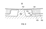
- Fig. 9 is a partial cross sectional view (local ZX plane) of stowed blocker doors showing the circumferential arrangement.
- Figure 10 is a view of a stowed blocker door with an alternative (integrated) seal.
- a ducted fan gas turbine engine generally indicated at 10 has a principal and rotational axis 11.
- the engine 10 comprises a propulsive fan 13 and a core engine 9 having, in axial flow series, an air intake 12, an intermediate pressure compressor 14, a high-pressure compressor 15, combustion equipment 16, a high-pressure turbine, an intermediate-pressure turbine 18, a low-pressure turbine 19 and terminating with a core exhaust nozzle 20.
- a nacelle 21 generally surrounds the engine 10 and defines the intake 12, a bypass duct 22 and an exhaust nozzle 23.
- the gas turbine engine 10 works in the conventional manner so that air entering the intake 11 is accelerated by the fan 13 to produce two air flows: a first airflow A into the intermediate pressure compressor 14 and a second airflow B which passes through a bypass duct 22 to provide propulsive thrust.
- the intermediate pressure compressor 14 compresses the airflow A directed into it before delivering that air to the high pressure compressor 15 where further compression takes place.
- the compressed air exhausted from the high pressure compressor 15 is directed into the combustor 16 where it is mixed with fuel and combusted.
- the resultant hot combustion products then expand through, and thereby drive, the high, intermediate and low-pressure turbines 17, 18, 19 before being exhausted through the nozzles 20 to provide additional propulsive thrust.
- the high, intermediate and low pressure turbines 17, 18, 19 respectively drive the high, intermediate pressure compressors 15, 14 and the fan 13 by suitable interconnecting shafts.
- a centre plug 29 is positioned within the core exhaust nozzle 20 to provide a form for the core gas flow A to expand against and to smooth its flow from the core engine.
- the centre plug 29 extends rearward of the cone nozzle's exit plane 27.
- the fan is circumferentially surrounded by a structural member in the form of a fan casing 24 which is supported by an annular array of outlet guide vanes 28.
- the fan casing 24 comprises a rigid containment casing 25 and attached rearwardly thereto is a rear fan casing 26.
- the gas turbine engine 10 is installed under an aircraft wing 7 via a pylon 8.
- the nacelle 21 comprises an axially forward cover 35 (fan cowl) and a translatable cowl 37. Both the cover and the cowl are provided by C-shaped openable doors with each door being separately hinged to the aircraft pylon 8.
- the nacelle has a thrust reverser unit 31 which is formed from a number of cascade panels arranged sequentially around the circumference of the engine 10. The hinged doors permit access to the engine core for maintenance or inspection purposes.
- Figure 2 depicts the open nacelle 21 has hinges positioned at the top of the engine or on the pylon and which permits each part of the C duct defined by the cover 35, the translating cowl 37 and inner fixed structure 40 to rotate away from the engine to permit access thereto. Both the cowl and the cover 35 can pivot away from the engine.
- the thrust reverser unit 31 is mounted to the cover and can pivot away from the engine with the cover.
- the cowl 37 is provided with an axially forward tongue 60 which is formed of two parts 60a and 60b extending from each of the two doors forming the translatable cowl.
- the cover 35 has a recess which engages the tongue when the cowl and cover are closed to provide a streamlined external surface for the nacelle.
- translatable cowl is in its stowed position such that the cowl abuts the axially forward cover.
- translatable thrust reverser unit is in an axial forward position in contrast to Figure 4 , where the unit has been deployed rearwardly to open the cascades 41.
- the tongue 60 in the deployed position of the cowl is aligned with the axial position of the cascade.
- the tongue 60 is located 180 degrees from the pylon (not shown) and is located on the underside of the engine.
- FIG 5 is a partial cross section through the cascade and cowl arrangement of Figure 3 .
- the cowl 37 has a bifurcated fairing that has a radially outer wall 62 that forms an airwashed surface for the external surface of the nacelle and a radially inner wall 64 that forms an airwashed surface for the bypass duct 22.
- a blocker door 39 is located against the radially inner surface of the radially inner wall 64 in the stowed position with the inner wall of the fairing providing additional support for the blocker door against the pressures of the flow through the bypass.
- the inner wall is stepped 66 to enable the blocker door to be recessed in the stowed position in order to provide a streamlined surface.
- a frame 68 joins the radially inner and outer walls (64,62).
- a cavity 70 within which the cascade 41 is located.
- the cascade When the cowl is in the stowed position of Figure 3 and 5 the cascade is isolated from the main flow through the bypass duct by the blocker door 39 and the radially inner wall 64 of the fairing. In addition, any leakage flow through either of these parts is inhibited from leaving the engine by the radially outer wall 62 of the cowl which seals against the cover 35. Any parasitic air flows inside the cavity 70 reduces the performance of the powerplant and therefore it is imperative to reduce them to minimum.
- the cascade 41 comprises an arrangement of vanes that are designed to turn a flow of air from the bypass duct when the cowl is translated to its open position towards the front of the engine to provide the reverse thrust relative to the normal direction of thrust generated by the engine.
- the cascade is assembled as a series of panels each of which provides a segment of the circumference of the thrust reverser.
- the cowl 37 is shown in its deployed position which is axially rearward of the stowed position.
- the blocker doors 39 are connected to the trans cowl via hinges (for axial translation of the blocker doors) and by linkages to the inner fixed structure (for rotation of the blocker doors) to direct the bypass flow through the cascades where the flow is turned in a forward direction and through a passage opened in the outer wall of the nacelle by the axially rearward movement of the outer wall.
- the flow of air through the cascade is shown by the arrows B and C.
- FIG. 7 is a perspective view of the blocker doors 39 arranged in their stowed position.
- Each door has a generally trapezoidal form which is mounted within a correspondingly shaped depression in the inner wall 64 of the translatable cowl.
- the leakage,parasitic flow in cavity 70, past the stowed blocker panels can reduce the overall efficiency of the engine and it is desirable to minimise this leakage.
- the blocker panels are formed as an assembly including a backskin 100, an internal support material 102 (honeycomb) and an air-washed facing sheet 104.
- the backskin is moulded or otherwise formed into a tray having a base 106, side walls 108, and a flange 110 which protrudes from the side walls.
- the backskin is formed of metal or, more preferably, a composite material which may be formed of a laminate of individual plies of carbon or glass fibres held within a resin matrix.
- the flange extends around the periphery of the tray and provides a surface to which the facing sheet can be joined.
- the tray is filled with the internal support material that provides rigidity to the blocker doors so that on deployment into the gas flow when reverse thrust is required the doors can withstand the high force of the flow.
- the support material is preferably in the form of a honeycomb, which, when combined with perforated facing sheet 104, contributes to a noise insulation lining as well as providing the required strength.
- the tray is closed with a facing sheet 104, bonded or otherwise secured to the flange 110.
- the facing sheet has some flexibility and is preferably formed of a rubber or other elastomeric material that can be perforated to allow a small flow of air into and out of the tray that assists with the acoustic damping.
- the facing sheet 104 By making the facing sheet 104 from elastomeric material or rubber and making the rubber sheet protrude beyond the periphery of the flange to provide a "lip" seal portion 112 and in the stowed position seals against the inner wall 64 of the translatable cowl and against the cascade support structure 43 along its and beneficially all edges.
- the pressure of the air in the bypass duct forces the seal against a land on the inner wall of the cowl.
- the seal is enhanced by the pressure in the bypass duct which presses the seal against the inner wall of the cowl in use to further limit the parasitic flow of air past the seal.
- seals have been depicted and described here as flat ("lip") seals it will be appreciated that other forms of seals e.g. P or Omega seals that have a shaped end may also be used.
- Figure 10 depicts an alternative arrangement, where the inner wall 64 has a step to provide a ledge 114 that supports the seal.
- the "omega" seal 116 has an elongate portion 117 and a bulbous portion 118 integrally moulded together.
- sealing is improved by providing two seal locations: the first against the ledge on the land, the second against the side of the depression 120 in the inner wall 64.
- the choice of material, material thickness and/or shape 112 & 118 and its programmed hardness for the facing sheet can also be selected to achieve the desired functionality for the seal.
- the cover is formed of a thermoplastic or thermosetting resin or rubber material it is possible to provide this as a moulded construction with graded material and/ or functional properties.
- the periphery of the cover that seals against the outer wall of the bypass duct may therefore be formed to be more rigid or more flexible than the inner section of the cover which secures the cover to the tray.
- the facing sheet is formed of a fire resistant material the use of the blocker doors as a fire barrier is enhanced.
- Access to the core engine and associated accessories is achieved by deploying the thrust reverser unit and/or rotating open the translating cowls.
- the core fairing 40 which is hinged independently, is then rotated open.
- individual panels may be provided and readily removed.
Landscapes
- Engineering & Computer Science (AREA)
- Chemical & Material Sciences (AREA)
- Combustion & Propulsion (AREA)
- Mechanical Engineering (AREA)
- General Engineering & Computer Science (AREA)
- Structures Of Non-Positive Displacement Pumps (AREA)
- Body Structure For Vehicles (AREA)
- Turbine Rotor Nozzle Sealing (AREA)
Applications Claiming Priority (1)
| Application Number | Priority Date | Filing Date | Title |
|---|---|---|---|
| GBGB1219368.6A GB201219368D0 (en) | 2012-10-29 | 2012-10-29 | Aeroengine thrust reverser arrangement |
Publications (2)
| Publication Number | Publication Date |
|---|---|
| EP2725217A2 true EP2725217A2 (fr) | 2014-04-30 |
| EP2725217A3 EP2725217A3 (fr) | 2018-04-04 |
Family
ID=47358763
Family Applications (1)
| Application Number | Title | Priority Date | Filing Date |
|---|---|---|---|
| EP13005068.5A Withdrawn EP2725217A3 (fr) | 2012-10-29 | 2013-10-23 | Moteur d'aéronef comprenant un inverseur de poussée |
Country Status (3)
| Country | Link |
|---|---|
| US (1) | US9784213B2 (fr) |
| EP (1) | EP2725217A3 (fr) |
| GB (1) | GB201219368D0 (fr) |
Cited By (2)
| Publication number | Priority date | Publication date | Assignee | Title |
|---|---|---|---|---|
| FR3029573A1 (fr) * | 2014-12-05 | 2016-06-10 | Airbus Operations Sas | Inverseur de poussee pour un ensemble moteur d'aeronef, nacelle et ensemble moteur correspondants |
| FR3068080A1 (fr) * | 2017-06-21 | 2018-12-28 | Airbus Operations | Nacelle d'aeronef comportant un volet inverseur et un joint |
Families Citing this family (10)
| Publication number | Priority date | Publication date | Assignee | Title |
|---|---|---|---|---|
| GB201219366D0 (en) * | 2012-10-29 | 2012-12-12 | Rolls Royce Deutschland & Co Kg | Aeroengine thrust reverser arrangement |
| FR2999155B1 (fr) * | 2012-12-12 | 2014-11-21 | Aircelle Sa | Ensemble propulsif pour aeronef |
| US9920709B2 (en) | 2015-02-19 | 2018-03-20 | Rohr, Inc. | Dielectric elastomer device to fill steps or gaps in a thrust reverser |
| US10502160B2 (en) | 2016-02-09 | 2019-12-10 | General Electric Company | Reverse thrust engine |
| US10563614B2 (en) * | 2016-08-17 | 2020-02-18 | Honeywell International Inc. | Composite translating cowl assembly for a thrust reverser system |
| US10406729B2 (en) | 2016-08-29 | 2019-09-10 | The Boeing Company | Compression molding assembly and methods for molding a thermoplastic blocker door |
| US10794326B2 (en) | 2016-08-29 | 2020-10-06 | The Boeing Company | Blocker door assembly having a thermoplastic blocker door for use in a turbine engine |
| ES2758187T3 (es) * | 2017-02-17 | 2020-05-04 | MTU Aero Engines AG | Disposición de sellado para una turbina de gas |
| US11472564B2 (en) | 2019-03-12 | 2022-10-18 | Rohr, Inc. | Seal arrangement |
| CN111365144B (zh) * | 2020-02-28 | 2023-03-24 | 上海新力动力设备研究所 | 一种柔性接头及采用该柔性接头的固体火箭发动机喷管 |
Family Cites Families (19)
| Publication number | Priority date | Publication date | Assignee | Title |
|---|---|---|---|---|
| US3797785A (en) | 1972-08-31 | 1974-03-19 | Rohr Industries Inc | Thrust modulating apparatus |
| US4026105A (en) * | 1975-03-25 | 1977-05-31 | The Boeing Company | Jet engine thrust reverser |
| FR2635825B1 (fr) * | 1988-08-29 | 1990-11-30 | Hurel Dubois Avions | Inverseur de poussee pour moteur a reaction de type a portes equipees de volets auxiliaires |
| FR2651278B1 (fr) | 1989-08-23 | 1994-05-06 | Hispano Suiza | Inverseur a grilles sans capot coulissant pour turboreacteur. |
| US5243817A (en) * | 1990-07-05 | 1993-09-14 | Rohr, Inc. | Thrust reverser for fan jet aircraft engines |
| FR2683859B1 (fr) | 1991-11-15 | 1994-02-18 | Hispano Suiza | Inverseur de poussee de turboreacteur a double flux. |
| US5575147A (en) | 1994-12-22 | 1996-11-19 | United Technologies Corporation | Compact thrust reverser |
| FR2738291B1 (fr) | 1995-09-06 | 1997-09-26 | Hispano Suiza Sa | Inverseur de poussee de turboreacteur a portes associees a un panneau amont formant ecope |
| US5806302A (en) * | 1996-09-24 | 1998-09-15 | Rohr, Inc. | Variable fan exhaust area nozzle for aircraft gas turbine engine with thrust reverser |
| EP0852290A1 (fr) * | 1996-12-19 | 1998-07-08 | SOCIETE DE CONSTRUCTION DES AVIONS HUREL-DUBOIS (société anonyme) | Inverseur de poussée de turboréacteur à double flux avec grand taux de dilution |
| US5927647A (en) * | 1997-09-24 | 1999-07-27 | Rohr, Inc. | Blocker door frame pressure structure for translating cowl of cascade thrust reverser for aircraft jet engine |
| GB9915637D0 (en) * | 1999-07-06 | 1999-09-01 | Rolls Royce Plc | A rotor seal |
| GB2395175B (en) | 2000-10-19 | 2005-01-05 | Short Brothers Plc | Aircraft propulsive power unit |
| US7007476B2 (en) * | 2003-04-11 | 2006-03-07 | Parker-Hannifin Corporation | Gas turbine fuel system staging valves |
| FR2887854B1 (fr) * | 2005-06-30 | 2008-08-08 | Airbus France Sas | Nacelle pour aeronef et aeronef muni d'au moins une telle nacelle |
| US7600371B2 (en) | 2005-10-18 | 2009-10-13 | The Boeing Company | Thrust reversers including support members for inhibiting deflection |
| FR2915526B1 (fr) | 2007-04-24 | 2009-05-29 | Aircelle Sa | Dispositif de variation de section de tuyere secondaire associe a un inverseur a portes a dispositif de lissage de veine. |
| FR2946094B1 (fr) * | 2009-06-02 | 2014-04-18 | Aircelle Sa | Inverseur de poussee pour nacelle de turboreacteur double flux. |
| US8820088B2 (en) * | 2010-07-27 | 2014-09-02 | United Technologies Corporation | Variable area fan nozzle with acoustic system for a gas turbine engine |
-
2012
- 2012-10-29 GB GBGB1219368.6A patent/GB201219368D0/en not_active Ceased
-
2013
- 2013-10-22 US US14/060,044 patent/US9784213B2/en not_active Expired - Fee Related
- 2013-10-23 EP EP13005068.5A patent/EP2725217A3/fr not_active Withdrawn
Non-Patent Citations (1)
| Title |
|---|
| None * |
Cited By (3)
| Publication number | Priority date | Publication date | Assignee | Title |
|---|---|---|---|---|
| FR3029573A1 (fr) * | 2014-12-05 | 2016-06-10 | Airbus Operations Sas | Inverseur de poussee pour un ensemble moteur d'aeronef, nacelle et ensemble moteur correspondants |
| US9989010B2 (en) | 2014-12-05 | 2018-06-05 | Airbus Operations (Sas) | Thrust reverser for an aircraft engine, pod assembly and corresponding powerplant |
| FR3068080A1 (fr) * | 2017-06-21 | 2018-12-28 | Airbus Operations | Nacelle d'aeronef comportant un volet inverseur et un joint |
Also Published As
| Publication number | Publication date |
|---|---|
| GB201219368D0 (en) | 2012-12-12 |
| EP2725217A3 (fr) | 2018-04-04 |
| US20140116025A1 (en) | 2014-05-01 |
| US9784213B2 (en) | 2017-10-10 |
Similar Documents
| Publication | Publication Date | Title |
|---|---|---|
| US9784213B2 (en) | Aeroengine thrust reverser arrangement | |
| US9932932B2 (en) | Aeroengine thrust reverser arrangement | |
| US7874142B2 (en) | Aeroengine thrust reverser | |
| US8235646B2 (en) | Aeroengine nozzle | |
| US7866142B2 (en) | Aeroengine thrust reverser | |
| US8316632B2 (en) | Thrust reverser configuration for a short fan duct | |
| CA2800049C (fr) | Joint d'etancheite pour buse a jet plat a surface variable | |
| EP2660454A2 (fr) | Ensemble d'inverseur de poussée et procédé de fonctionnement | |
| US20040238687A1 (en) | Aeroengine nacelle | |
| US8307628B2 (en) | Rear fan case for a gas turbine engine | |
| EP3228854B1 (fr) | Nacelle de moteur de turbine à gaz d'aéronef | |
| US10851734B2 (en) | Thrust reverser assembly | |
| EP3441601B1 (fr) | Butée d'inverseur de poussée de moteur à turbine | |
| US9932846B2 (en) | Aeroengine sealing arrangement | |
| US9776726B2 (en) | Gas turbine cowl | |
| US10138843B2 (en) | Drag link assembly for a thrust reverser |
Legal Events
| Date | Code | Title | Description |
|---|---|---|---|
| PUAI | Public reference made under article 153(3) epc to a published international application that has entered the european phase |
Free format text: ORIGINAL CODE: 0009012 |
|
| 17P | Request for examination filed |
Effective date: 20131023 |
|
| AK | Designated contracting states |
Kind code of ref document: A2 Designated state(s): AL AT BE BG CH CY CZ DE DK EE ES FI FR GB GR HR HU IE IS IT LI LT LU LV MC MK MT NL NO PL PT RO RS SE SI SK SM TR |
|
| AX | Request for extension of the european patent |
Extension state: BA ME |
|
| PUAL | Search report despatched |
Free format text: ORIGINAL CODE: 0009013 |
|
| AK | Designated contracting states |
Kind code of ref document: A3 Designated state(s): AL AT BE BG CH CY CZ DE DK EE ES FI FR GB GR HR HU IE IS IT LI LT LU LV MC MK MT NL NO PL PT RO RS SE SI SK SM TR |
|
| AX | Request for extension of the european patent |
Extension state: BA ME |
|
| RIC1 | Information provided on ipc code assigned before grant |
Ipc: F02K 1/72 20060101AFI20180223BHEP |
|
| STAA | Information on the status of an ep patent application or granted ep patent |
Free format text: STATUS: REQUEST FOR EXAMINATION WAS MADE |
|
| 17P | Request for examination filed |
Effective date: 20181002 |
|
| RBV | Designated contracting states (corrected) |
Designated state(s): AL AT BE BG CH CY CZ DE DK EE ES FI FR GB GR HR HU IE IS IT LI LT LU LV MC MK MT NL NO PL PT RO RS SE SI SK SM TR |
|
| STAA | Information on the status of an ep patent application or granted ep patent |
Free format text: STATUS: EXAMINATION IS IN PROGRESS |
|
| 17Q | First examination report despatched |
Effective date: 20190208 |
|
| GRAP | Despatch of communication of intention to grant a patent |
Free format text: ORIGINAL CODE: EPIDOSNIGR1 |
|
| STAA | Information on the status of an ep patent application or granted ep patent |
Free format text: STATUS: GRANT OF PATENT IS INTENDED |
|
| INTG | Intention to grant announced |
Effective date: 20201103 |
|
| STAA | Information on the status of an ep patent application or granted ep patent |
Free format text: STATUS: THE APPLICATION IS DEEMED TO BE WITHDRAWN |
|
| 18D | Application deemed to be withdrawn |
Effective date: 20210316 |