EP2725207A1 - Centrale avec épurateur à la vapeur et accumulateur de gaz - Google Patents
Centrale avec épurateur à la vapeur et accumulateur de gaz Download PDFInfo
- Publication number
- EP2725207A1 EP2725207A1 EP12190351.2A EP12190351A EP2725207A1 EP 2725207 A1 EP2725207 A1 EP 2725207A1 EP 12190351 A EP12190351 A EP 12190351A EP 2725207 A1 EP2725207 A1 EP 2725207A1
- Authority
- EP
- European Patent Office
- Prior art keywords
- steam reformer
- gas
- fuel
- reforming
- synthesis gas
- Prior art date
- Legal status (The legal status is an assumption and is not a legal conclusion. Google has not performed a legal analysis and makes no representation as to the accuracy of the status listed.)
- Withdrawn
Links
Images


Classifications
-
- F—MECHANICAL ENGINEERING; LIGHTING; HEATING; WEAPONS; BLASTING
- F01—MACHINES OR ENGINES IN GENERAL; ENGINE PLANTS IN GENERAL; STEAM ENGINES
- F01K—STEAM ENGINE PLANTS; STEAM ACCUMULATORS; ENGINE PLANTS NOT OTHERWISE PROVIDED FOR; ENGINES USING SPECIAL WORKING FLUIDS OR CYCLES
- F01K17/00—Using steam or condensate extracted or exhausted from steam engine plant
- F01K17/02—Using steam or condensate extracted or exhausted from steam engine plant for heating purposes, e.g. industrial, domestic
- F01K17/025—Using steam or condensate extracted or exhausted from steam engine plant for heating purposes, e.g. industrial, domestic in combination with at least one gas turbine, e.g. a combustion gas turbine
-
- F—MECHANICAL ENGINEERING; LIGHTING; HEATING; WEAPONS; BLASTING
- F01—MACHINES OR ENGINES IN GENERAL; ENGINE PLANTS IN GENERAL; STEAM ENGINES
- F01K—STEAM ENGINE PLANTS; STEAM ACCUMULATORS; ENGINE PLANTS NOT OTHERWISE PROVIDED FOR; ENGINES USING SPECIAL WORKING FLUIDS OR CYCLES
- F01K23/00—Plants characterised by more than one engine delivering power external to the plant, the engines being driven by different fluids
- F01K23/02—Plants characterised by more than one engine delivering power external to the plant, the engines being driven by different fluids the engine cycles being thermally coupled
- F01K23/06—Plants characterised by more than one engine delivering power external to the plant, the engines being driven by different fluids the engine cycles being thermally coupled combustion heat from one cycle heating the fluid in another cycle
- F01K23/067—Plants characterised by more than one engine delivering power external to the plant, the engines being driven by different fluids the engine cycles being thermally coupled combustion heat from one cycle heating the fluid in another cycle the combustion heat coming from a gasification or pyrolysis process, e.g. coal gasification
-
- F—MECHANICAL ENGINEERING; LIGHTING; HEATING; WEAPONS; BLASTING
- F22—STEAM GENERATION
- F22B—METHODS OF STEAM GENERATION; STEAM BOILERS
- F22B1/00—Methods of steam generation characterised by form of heating method
- F22B1/02—Methods of steam generation characterised by form of heating method by exploitation of the heat content of hot heat carriers
- F22B1/18—Methods of steam generation characterised by form of heating method by exploitation of the heat content of hot heat carriers the heat carrier being a hot gas, e.g. waste gas such as exhaust gas of internal-combustion engines
- F22B1/1807—Methods of steam generation characterised by form of heating method by exploitation of the heat content of hot heat carriers the heat carrier being a hot gas, e.g. waste gas such as exhaust gas of internal-combustion engines using the exhaust gases of combustion engines
- F22B1/1815—Methods of steam generation characterised by form of heating method by exploitation of the heat content of hot heat carriers the heat carrier being a hot gas, e.g. waste gas such as exhaust gas of internal-combustion engines using the exhaust gases of combustion engines using the exhaust gases of gas-turbines
-
- Y—GENERAL TAGGING OF NEW TECHNOLOGICAL DEVELOPMENTS; GENERAL TAGGING OF CROSS-SECTIONAL TECHNOLOGIES SPANNING OVER SEVERAL SECTIONS OF THE IPC; TECHNICAL SUBJECTS COVERED BY FORMER USPC CROSS-REFERENCE ART COLLECTIONS [XRACs] AND DIGESTS
- Y02—TECHNOLOGIES OR APPLICATIONS FOR MITIGATION OR ADAPTATION AGAINST CLIMATE CHANGE
- Y02E—REDUCTION OF GREENHOUSE GAS [GHG] EMISSIONS, RELATED TO ENERGY GENERATION, TRANSMISSION OR DISTRIBUTION
- Y02E20/00—Combustion technologies with mitigation potential
- Y02E20/14—Combined heat and power generation [CHP]
-
- Y—GENERAL TAGGING OF NEW TECHNOLOGICAL DEVELOPMENTS; GENERAL TAGGING OF CROSS-SECTIONAL TECHNOLOGIES SPANNING OVER SEVERAL SECTIONS OF THE IPC; TECHNICAL SUBJECTS COVERED BY FORMER USPC CROSS-REFERENCE ART COLLECTIONS [XRACs] AND DIGESTS
- Y02—TECHNOLOGIES OR APPLICATIONS FOR MITIGATION OR ADAPTATION AGAINST CLIMATE CHANGE
- Y02E—REDUCTION OF GREENHOUSE GAS [GHG] EMISSIONS, RELATED TO ENERGY GENERATION, TRANSMISSION OR DISTRIBUTION
- Y02E20/00—Combustion technologies with mitigation potential
- Y02E20/16—Combined cycle power plant [CCPP], or combined cycle gas turbine [CCGT]
- Y02E20/18—Integrated gasification combined cycle [IGCC], e.g. combined with carbon capture and storage [CCS]
Definitions
- the present invention relates to a power plant having a combustible combustion-emitting combustion device, a steam reformer for generating synthesis gas by means of reforming a hydrocarbon-containing first fuel with water, wherein the steam reformer is thermally connected to the combustion device such that during combustion operation of the combustion device of the steam reformer with Heat from the exhaust gas of the combustion device can be supplied. Furthermore, the present invention relates to a method for operating such a power plant as well as a method for retrofitting an existing power plant.
- the overall reaction resulting from the two above reactions 1 and 2 is furthermore endothermic, so that heat must be added to the reaction system so that the overall reaction can take place.
- a metal catalyst typically nickel
- the reaction temperatures are typically between 650 ° C and 1100 ° C. Due to these high reaction temperatures, the reaction equilibrium of reaction 1 shifts sufficiently far to the right side and promotes the formation of hydrogen, so that the conversion into synthesis gas can take place on an economic scale.
- a comparable proposal for the integration of a steam reforming in a gas turbine power plant is, for example, in the publication "gas turbine combined cycle with CO 2 -capture using auto-thermal reforming of natural gas", Thormod Andersen and Hanne M. Kvamsdal and Olav Bolland in Proceedings of ASME TURBO EXPO 2000, Land, Sea and Air, May 8-11, 2000, Kunststoff, Germany , proposed.
- the proposal provides, in a multi-stage continuous process, to convert natural gas with water to a synthesis gas, with the heat required for the course of the reforming process being taken from the exhaust gas of the regularly operated gas turbine.
- the advantage of reforming hydrocarbonaceous fuels, especially methane, in a natural gas is that a mixture of carbon monoxide and hydrogen is formed by the endothermic reaction 1, which has a significantly higher calorific value in comparison to the starting materials methane and water.
- the reverse reaction according to reaction 1 for the formation of methane is highly exothermic.
- the synthesis gas generated during the reforming process is derived from the power plant and requires a suitable pipeline infrastructure.
- the proposed solution should allow more flexible operation of the power plant, but at the same time the overall efficiency of the power plant process should be improved. It is another object of the present invention to propose a flexible and efficient method for operating such a power plant. Likewise, it turns out to be desirable to operate existing power plants more flexible and efficient by suitable retrofitting.
- a power plant which has an exhaust combustion device emitting flue gas combustion device, and a steam reformer for generating synthesis gas by reforming a hydrocarbon-containing first fuel with water, wherein the steam reformer is thermally connected to the combustion device such that during combustion operation
- the combustion device of the steam reformer can be supplied with heat from the exhaust gas of the combustion device, wherein furthermore a gas storage is included, which is fluidly connected to the steam reformer for intermediate storage of the synthesis gas.
- a gas reservoir is included in the power plant, which can receive the synthesis gas for temporary storage derived from the steam reformer. Consequently, the synthesis gas is also available in principle for recycling in the power plant process again.
- the return of the bound in chemical form energy in the power plant process increases the one hand, the overall efficiency of the power plant process, as well as the other hand, the flexibilization, as needed, the available chemical energy of the synthesis gas from the gas storage in the power plant process can be returned.
- the synthesis gas has a higher calorific value than about the starting material of the reforming methane, which may also be present in large quantities in natural gas. Consequently, the synthesis gas is a high-calorie fuel, which is also able to release more thermal energy with suitable combustion than, for example, the fuel methane. This ensures a high energy storage density, which can also be achieved relatively low loss.
- the possible temporary storage of the synthesis gas due to the gas storage facility covered by the power plant as well as feedback into the power plant process thus permit efficient storage in chemical form of the waste heat of the exhaust gas emitted during operation of the combustion device.
- existing power plants can easily be retrofitted by a suitable gas storage and fluidly connected to the steam reformer that the synthesis gas generated in the steam reformer can be temporarily stored in order to subsequently lead back into the power plant process.
- the first fuel that is supplied to the combustor for firing operation is methane or a mixture of methane, such as contained in natural gas.
- the combustion device need not be designed as a gas turbine, but may also be designed in the sense of a conventional combustion chamber of a solid fuel (eg coal, biomass, waste) or oil power plant.
- a solid fuel eg coal, biomass, waste
- oil power plant e.g coal, biomass, waste
- the first fuel is to be understood as the fuel fed to the steam reformer.
- the synthesis gas formed in the steam reformer is fed to the gas storage according to the invention.
- the synthesis gas of the gas storage may be redirected in a cyclic process to the steam reformer for further reforming.
- the synthesis gas is at the same time a first fuel fed to the steam reformer.
- the first fuel may be identical to the synthesis gas, or both may have portions of the other.
- the gas storage of the power plant is further fluidly connected to the combustion device, so that synthesis gas of the combustion device can be supplied for combustion.
- the synthesis gas is provided for combustion in the incinerator. Due to the intermediate storage in the gas storage, the combustion device can also be supplied with a time delay to the synthesis gas for combustion as required. On the one hand, this increases the temporal flexibility of the power plant, as well as the gas efficiency, since the synthesis gas returns its energy back into the combustion process of the incinerator.
- an electrical heating device is provided which is provided for the thermal conditioning of the first fuel and / or water fed to the steam reformer for reforming.
- the steam reformer can also be heated completely or partially electrically.
- the electrical heating device can be operated in particular via electrical energy taken from the public power supply networks. This allows the heater be operated at low cost in the prevalence of surplus electricity in the public power supply networks.
- the thermal energy released by the electric heater can be temporarily stored in chemical form, namely in the form of the synthesis gas. This is then the power plant process for further use such as for reconversion available again. By operating the heater, operation of the steam reformer is possible even without operation of the power plant.
- the electrical heating device is connected between the steam reformer and the gas reservoir.
- synthesis gas taken from the gas storage can be thermally pretreated for renewed reforming in the steam reformer before it is introduced into the steam reformer.
- the electrical heating device is connected in a line which ensures that the first fuel and / or water is supplied to the steam reformer.
- common to all embodiments is a thermal conditioning of the educts, which are converted in the reformer to synthesis gas, or a direct heating of the steam reformer, wherein the thermal treatment can be carried out independently of the operation of the combustion device of the power plant.
- a gas preheater which thermally conditions the synthesis gas discharged from the gas reservoir, and in particular is fluidically interconnected between the combustion device and the gas reservoir. Accordingly, the synthesis gas taken from the gas reservoir can be thermally conditioned, so that, for example, a relatively more efficient combustion process can take place in the combustion device.
- the gas preheater can be designed as a conventional heat exchanger or as an electric heater.
- the gas storage is at least partially connected to a heat exchanger, or is designed as such, so that the heat of the synthesis gas stored therein can be transferred to a heat medium. Since, in particular, the reforming takes place in the steam reformer at high temperatures, the synthesis gas discharged from the steam reformer is likewise supplied to the gas reservoir at a comparatively high temperature level. If the synthesis gas temporarily stored in the gas accumulator is not returned to use in the vicinity of time, the thermal energy of the synthesis gas temporarily stored in the gas accumulator is sometimes lost. To harness this energy, the gas storage is connected in accordance with the execution of a heat exchanger, or designed as such, so that the energy contained therein can be harnessed.
- the heat medium is the first fuel fed to the steam reformer for reforming. Accordingly, the thermal energy in the gas storage can be transferred to the first fuel, so that it already undergoes a suitable thermal conditioning prior to introduction into the steam reformer.
- the steam reformer is fluidly connected to the gas storage such that the first fuel supplied to the steam reformer for reforming is removed from the gas storage.
- a cyclic treatment of the first fuel introduced into the gas storage takes place by reforming in the steam reformer.
- the gas reservoir is first filled with a gaseous first fuel, and then fed in repeated cyclical steps to the reformer for steam reforming.
- the synthesis gas which is formed in each case during the steam reforming, in turn, becomes the gas storage for intermediate storage supplied, wherein the first fuel mixes with the recirculated synthesis gas and thus forms a first fuel, which has a higher calorific value each after a successful reforming process than before.
- the gas storage has a plurality of separate cells in which the first fuel or the recycled synthesis gas from the steam reformer is stored unmixed and thus separated from each other. Accordingly, the synthesis gas temporarily stored in the gas reservoir only undergoes a reforming process in each case.
- a heat exchanger is provided, which is designed to transfer heat of the synthesis gas derived from the steam reformer to the first fuel fed to the steam reformer and / or to the water fed to the steam reformer.
- the heat exchanger is therefore connected thermally between the gas storage and the steam reformer. It allows the heat that the synthesis gas has after discharging from the reformer to be suitably transferred to the first fuel before it is fed to the reformer for steam reforming.
- the thermal conditioning reduces the heat requirement of the reforming process, which otherwise must be covered primarily by the heat of the exhaust gas of the combustion device.
- the gas storage is designed as a tube memory.
- Tube memories allow a standardized construction and will allow a subsequent expansion of the storage capacity, as far as necessary.
- Tube stores are typically designed for pressures up to 100 bar and allow gas storage independent of geological conditions. In this way, tubular storages differ in particular from cavern storages, which can only be put into operation under suitable geological conditions.
- the power plant comprise a drying unit, which allows water to be separated from the synthesis gas derived from the gas storage.
- the synthesis gas still has a residual content of water. This can be deposited by means of the drying unit in a suitable manner.
- the synthesis gas for example, can be adjusted advantageously for further combustion by means of the combustion device of the power plant in terms of water content.
- drying is to be performed if the synthesis gas is to be introduced into a natural gas pipeline network for storage to meet the specifications of the supplied gas in terms of its dew point.
- a further heat exchanger is provided which makes the extraction of heat possible to transfer this to another medium transferred to. Due to the sometimes high water vapor content of the product gas of the steam reformer and the high gas pressure, the cooling of the product gas with partial or complete condensation of water vapor at relatively high temperatures (about 80-300 ° C) can be used to heat a consumer (industrial process, district heating network, etc.). ) to provide heat. The heat transfer for heat extraction, the water vapor content of the product gas of the reformer can be lowered, recovered water and heat proceeds can be achieved.
- the power plant comprises at least one gas turbine as a combustion device.
- the gas turbine may sometimes be necessary to adapt the gas turbine to the deviating quality of the fuel. This is especially the case when the hydrogen content in the synthesis gas is relatively high.
- a suitable retrofitting of the gas turbine for combustion of the synthesis gas derived from the gas storage is quite technically possible (see: Combustion of coal gas in Siemens gas turbines: Experiences during commissioning of the coal gasification combined cycle power plant Buggenun, N. Vortmeyer, B. Schetter, B. Becker, VDI report No. 1193, page 597 ff., 1995 ).
- the gas storage is corrosion resistant to water.
- the synthesis gas introduced into the gas reservoir further comprises traces of water, it is advantageous to form the gas storage corrosion resistant to moisture. Suitable for this purpose are corrosion-resistant steel alloys.
- such gas storage are sometimes buried in the ground and are thus exposed to moisture in the soil.
- the corrosion resistance of the gas reservoir also allows to operate the reforming process in the steam reformer with an excess of water, which is sometimes necessary to prevent carbon deposition on the catalyst of the steam reformer.
- an incomplete reaction of the reactants in the steam reformer may occur, so that even with the whereabouts of steam in the synthesis gas to be calculated.
- a plurality of gas reservoirs is included by the power plant, which independently with each other the steam reformer and / or the combustion device are fluidly connected and in particular can be switched independently of each other in fluid communication with the steam reformer.
- the circuit is in this case in particular by means of a suitable control or control via suitable adjusting means, such as valves.
- the plurality of gas reservoirs can thus serve independently for receiving synthesis gas derived from the steam reformer or for providing synthesis gas to the combustion device.
- different gas reservoirs can accommodate synthesis gas of different composition, the different synthesis gases differing in particular with regard to their calorific value.
- the operation of a power plant having a plurality of gas storage facilities can be made significantly more flexible and efficient.
- the steam reformer is supplied with just as much water for reforming, as is required for a stoichiometric reaction.
- the technical error to be considered is 10% at most.
- the reforming taking place in the steam reformer takes place virtually stoichiometrically, with the synthesis gas produced during the reforming being essentially free of water.
- the steam reformer is supplied with more water for reforming, as is required for a stoichiometric reaction, in particular with at least 25% more water is supplied, as is required for a stoichiometric reaction.
- the technical errors to be considered are at most 10%. Accordingly, complete conversion of the starting materials fed to the steam reformer can not take place, with the synthesis gas derived from the steam reformer still having water.
- the combustion device a gas-fired gas turbine, which can also be operated with steam injection, the additional water content in the synthesis gas sometimes proves to be advantageous because the combustion device no further water must be injected when the hydrous synthesis gas is burned.
- the reforming is carried out in the steam reformer at a temperature level of at most 650 ° C.
- the temperature level is between 450 ° C and 650 ° C.
- the operating temperature of the steam reformer is below the typical values known from the prior art. Due to the lower temperature values, however, it is possible to directly use the exhaust gas discharged from the combustion devices and to dispense with a further input of energy.
- the combustion devices are designed in particular as gas turbines whose exhaust gas temperatures are typically at most about 650 ° C.
- the reforming in the steam reformer is not carried out completely, in particular reaches at most a conversion of 80% of the maximum possible conversion.
- the advantages that result are comparable to the above-outlined advantages of those embodiments in which incomplete reaction of the starting materials takes place in the steam reformer.
- incomplete conversion causes the presence of water in the syngas derived from the steam reformer.
- the course of the reaction with the goal of incomplete conversion allows a reduction in the size of the steam reformer and the operation at varying, sometimes unfavorable operating conditions (flexible operation).
- the water required for the reforming in the steam reformer is supplied to the steam reformer as water vapor, which is generated in particular in a separate steam generator of liquid water.
- the steam can also be taken from the water-steam cycle of a power plant. Due to the introduction of steam into the steam reformer, no further thermal energy is needed to convert the water to the vapor phase for reforming.
- the water required for the reforming in the steam reformer is supplied to the steam reformer as liquid water.
- the evaporation of the water thus takes place in the steam reformer itself, so that the steam reformer, the required for the evaporation of water thermal energy must be additionally supplied.
- the supply of liquid water to the Steam reformer is particularly easy to implement technically.
- an electrical heating device is provided for the thermal conditioning of the first fuel and / or water fed to the steam reformer for reforming or the reformer is electrically heated directly, at least partially, preferably exclusively with excess current the public power supply network is supplied.
- the electric heater thus allows the conversion of electrical energy into thermal energy, which can be cached in the gas storage after reforming in the steam reformer in the form of chemical energy.
- excess electricity can be removed very cheaply or even against reimbursement from the public power supply networks, consequently, a very economical operation by means of the method according to the invention is possible.
- a second hydrocarbon-containing fuel is supplied to the combustion device of the combustion device, and the first hydrocarbon-containing fuel to the steam reformer, wherein the second fuel has a higher calorific value than the first fuel.
- the first fuel is lower calorific than the second.
- the reforming in the steam reformer should therefore adapt the low-calorie first fuel as far as its calorific value so that it can be suitably fed to the combustion device at a later time.
- the combustion device can be sufficiently supplied with high-calorie fuel, this is supplied to a correspondingly high calorific fuel.
- the operation of the incinerator by means of a high calorific Fuel may be necessary in particular if at a lower fuel quality, the combustion device would otherwise have to be adjusted.
- a combustion device designed as a gas turbine it can only be operated with a relatively high-calorie fuel without technical modification, but admixing low-calorie fuel is entirely conceivable.
- after suitable conversion of the first fuel in the steam reformer to a higher-calorie fuel it may be co-incinerated together with the second fuel at a later time.
- the synthesis gas from the gas storage and at the same time the second hydrocarbon-containing fuel are supplied to the combustion technology operation of the combustion device.
- Both fuels can be mixed, for example, before initiation and in a suitable ratio to each other to set an advantageous overall fuel level.
- the admixture of the synthesis gas to the second hydrocarbon-containing fuel ensures that the fluctuation of the total combustion value of the mixture can always be suitably adjusted for combustion in the combustion device.
- the mixing ratio of the second hydrocarbonaceous fuel to the synthesis gas may be adjusted according to the calorific value of the synthesis gas.
- the supply of the synthesis gas temporarily stored in the gas reservoir to the combustion device takes place only when the calorific value of the synthesis gas is at least 10% greater than the calorific value of the initially introduced first fuel. Consequently, the introduction and thus also admixing of the synthesis gas temporarily stored in the gas reservoir to the combustion device takes place only when the calorific value of the synthesis gas has been suitably conditioned.
- the calorific value of the synthesis gas can be estimated here on the basis of the chemical composition, or it can be derived on the basis of the reaction conditions or reaction time in the steam reformer.
- the supply of the synthesis gas temporarily stored in the gas reservoir to the incinerator can also be carried out in batches, i. from the gas storage, synthesis gas is only intermittently taken for combustion in the gas turbine, while at other times a second fuel gas, such as natural gas, is burned in the incinerator.
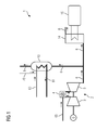
- FIG. 1 shows a schematic representation of a known from the prior art power plant 1, which in addition to a formed as a gas turbine combustion device 2, a steam reformer 10, which is designed to convert a first fuel 60 and water 70 to synthesis gas 61.
- the running in the steam reformer 10 reforming is in this case supplied with heat from the exhaust gas 6 of the combustion device 2.
- the power plant 1 which is designed as coupled to a steam reformer 10 gas and steam power plant, generates the heat required for the reforming by the combustion of a second fuel 65 in the combustion chamber 4 of the gas turbine.
- the second fuel 65 is hereby combusted with air compressed by the compressor unit 3 and expanded via the turbine unit 5 and discharged as exhaust gas 6.
- the exhaust gas 6 is fed to the steam reformer 10 and partially cooled by the heat transfer.
- the synthesis gas 61 generated therein is discharged, and fed to use outside the power plant.
- the chemical processes taking place in the steam reformer 10 essentially correspond to those in accordance with reaction 1 or reaction 2, and ensure that the first fuel 60, together with water 70 in the vapor phase, is essentially converted to carbon monoxide and hydrogen.
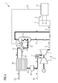
- FIG. 2 shows a first embodiment of the power plant 1 according to the invention, which is also designed as a gas and steam power plant. Alternatively, however, this embodiment may also be any type of power plant which has a suitable combustion device 2 which emits an exhaust gas 6 for the removal of thermal energy.
- the power plant 1 in addition to the combustion device 2 designed as a gas turbine, likewise comprises a steam reformer 10 for reforming a first fuel 60 and water 70.
- the water 70 is taken as water vapor from the water-steam circuit 15, or alternatively thermally treated by means of the heat recovery steam generator 14.
- the steam is introduced into the supply line of the first fuel 60 to the steam reformer 10.
- the heat necessary for the reforming is also provided by the exhaust gas 6 to the steam reformer according to the embodiment.
- the exhaust gas 6 is fed for this purpose as a partial flow directly to the steam reformer 10. After heat transfer in the steam reformer 10, the exhaust gas 6 is fed to a heat recovery steam generator 14. At the same time, another partial flow is fed to the heat recovery steam generator 14 in order to supply it with heat.
- the regulation or control of the two partial streams of the exhaust gas 6 is effected by suitable adjustment of two actuating means, especially two valves.
- additional heat can be taken from the heat recovery steam generator 14 for the operation of the steam reformer 10, if necessary. This in turn can be done via a targeted diversion of a heat-conducting process stream, but can also be realized by means of a suitably designed heat exchanger.
- the power plant 1 also has a gas reservoir 20, which is supplied with the first fuel 60.
- a gas reservoir 20 which is supplied with the first fuel 60.
- the steam reformer 10 To supply the steam reformer 10 with the first fuel 60, it is selectively removed from the gas reservoir 20 or fuel is supplied directly.
- the derived synthesis gas 61 is again supplied to the gas reservoir 20.
- the synthesis gas 61 can mix according to the embodiment with the first fuel 60, or be stored independently of each other in separate cells.
- a heat exchanger 40 is provided which allows the heat of the synthesis gas 61 to be transferred to the first fuel 60 before it is introduced into the steam reformer 10.
- the synthesis gas 61 located in the gas reservoir 20 is connected to the in the gas reservoir 20 in the Combustion chamber 4 of the gas turbine for combustion operation burned second fuel 65 is mixed. Both, synthesis gas 61 and second fuel 65, are mixed before being fed to the combustion chamber 4 in a suitably merged conduit.
- the synthesis gas taken from the gas reservoir 20 can be heated with a gas preheater 25.
- the gas preheater 25 can be designed here as an electric heater or as a heat exchanger.
- the combination of synthesis gas 61 and second fuel 65 produces a fuel mixture whose calorific value results from the individual fuel values of the unmixed substances. For a suitable adjustment of the total calorific value, it is provided according to the embodiment that only the amount of synthesis gas 61 is supplied to the second fuel 65 such that the total fuel value of the fuel mixture is within a predetermined band of permitted fuel values.
- FIG. 3 shows a further embodiment of the power plant 1 according to the invention, which differs from the in FIG. 2 shown power plant 1 only differs in that between gas storage 20 and steam reformer 10, an electric heater is connected in the supply line to the steam reformer 10, which allows to thermally condition the mixture of first fuel 60 and water 70.
- the heating device can also be integrated directly into the steam reformer 10 or the steam reformer 10 can be electrically heated directly.
- the thermal conditioning by means of the electric heater 30 only the thermal conditioning by the Support current of the exhaust gas 6 or by means of the heat recovery steam generator 14.
- FIG. 4 shows a further embodiment of the power plant 1 according to the invention, which differs from the in FIG. 2 shown power plant 1 only to the effect that the gas preheater 25 according to FIG. 2 is replaced by a drying unit 50.
- the drying unit 50 allows water to be separated from the synthesis gas 61 when it is removed from the gas reservoir 20.
- the water content supplied to the combustion chamber 4 of the gas turbine can thus be adjusted in a controlled manner so that, for example, the total water content of the gas mixture of synthesis gas 61 and second fuel 65 can be kept constant in a targeted manner within a predetermined value range.
- the drying unit 50 can be designed as a heat exchanger and be integrated between the heat exchanger 40 and the gas storage 20 in line 61. This makes it possible to remove heat from the product gas of the steam reformer 10 before the gas storage 20 and to lower the water vapor content by condensation. Due to the increased pressure level in the system, the condensation of the water vapor portion takes place at temperatures above 80 ° C and the heat can be used.
- the gas storage 20 fed first fuel 60 has a different from the second fuel 65 calorific value. Accordingly, the symbolized arrows are drawn as solid (first fuel 60) as well as dashed (second fuel 65). According execution it is conceivable to make a mixture of second fuel 65 and synthesis gas 61 only when the calorific value of the synthesis gas 61 exceeds a predetermined minimum value. It should be noted here that the calorific value of the first fuel 60 fed to the gas reservoir 20 is below this minimum value. Only by carrying out the reforming in the steam reformer 10 and by returning the resultant synthesis gas 61 into the gas reservoir 20, the gas reservoir 20 is increasingly filled with synthesis gas, which has a sufficiently high calorific value.
- the synthesis gas 61 temporarily stored in the gas reservoir 20 is fed to the combustion device 2 for the purpose of combustion technology operation. And according to a further preferred embodiment, it is conceivable that the synthesis gas 61 temporarily stored in the gas reservoir 20 is supplied again as the first fuel 60 to the steam reformer 10.
Landscapes
- Engineering & Computer Science (AREA)
- Chemical & Material Sciences (AREA)
- Combustion & Propulsion (AREA)
- Mechanical Engineering (AREA)
- General Engineering & Computer Science (AREA)
- Life Sciences & Earth Sciences (AREA)
- Sustainable Development (AREA)
- Sustainable Energy (AREA)
- Physics & Mathematics (AREA)
- Thermal Sciences (AREA)
- Hydrogen, Water And Hydrids (AREA)
Priority Applications (1)
| Application Number | Priority Date | Filing Date | Title |
|---|---|---|---|
| EP12190351.2A EP2725207A1 (fr) | 2012-10-29 | 2012-10-29 | Centrale avec épurateur à la vapeur et accumulateur de gaz |
Applications Claiming Priority (1)
| Application Number | Priority Date | Filing Date | Title |
|---|---|---|---|
| EP12190351.2A EP2725207A1 (fr) | 2012-10-29 | 2012-10-29 | Centrale avec épurateur à la vapeur et accumulateur de gaz |
Publications (1)
| Publication Number | Publication Date |
|---|---|
| EP2725207A1 true EP2725207A1 (fr) | 2014-04-30 |
Family
ID=47142956
Family Applications (1)
| Application Number | Title | Priority Date | Filing Date |
|---|---|---|---|
| EP12190351.2A Withdrawn EP2725207A1 (fr) | 2012-10-29 | 2012-10-29 | Centrale avec épurateur à la vapeur et accumulateur de gaz |
Country Status (1)
| Country | Link |
|---|---|
| EP (1) | EP2725207A1 (fr) |
Citations (6)
| Publication number | Priority date | Publication date | Assignee | Title |
|---|---|---|---|---|
| EP0127093A1 (fr) * | 1983-05-31 | 1984-12-05 | Kraftwerk Union Aktiengesellschaft | Centrale d'énergie intermédiaire avec une installation intégrée de gazéification de charbon |
| JPS62267526A (ja) * | 1986-05-15 | 1987-11-20 | Toyo Eng Corp | 発電方法 |
| WO1998045578A1 (fr) * | 1997-04-07 | 1998-10-15 | Siemens Westinghouse Power Corporation | Procede et systeme de recuperation thermochimique destines aux systemes de turbines a gaz |
| GB2331128A (en) * | 1997-11-04 | 1999-05-12 | Magnox Electric Plc | Gas-fuelled gas turbine power generation apparatus |
| WO2002033226A1 (fr) * | 2000-10-18 | 2002-04-25 | General Electric Company | Turbine a gaz a augmentation de puissance de cycle combine |
| US7707837B2 (en) | 2004-01-09 | 2010-05-04 | Hitachi, Ltd. | Steam reforming system |
-
2012
- 2012-10-29 EP EP12190351.2A patent/EP2725207A1/fr not_active Withdrawn
Patent Citations (6)
| Publication number | Priority date | Publication date | Assignee | Title |
|---|---|---|---|---|
| EP0127093A1 (fr) * | 1983-05-31 | 1984-12-05 | Kraftwerk Union Aktiengesellschaft | Centrale d'énergie intermédiaire avec une installation intégrée de gazéification de charbon |
| JPS62267526A (ja) * | 1986-05-15 | 1987-11-20 | Toyo Eng Corp | 発電方法 |
| WO1998045578A1 (fr) * | 1997-04-07 | 1998-10-15 | Siemens Westinghouse Power Corporation | Procede et systeme de recuperation thermochimique destines aux systemes de turbines a gaz |
| GB2331128A (en) * | 1997-11-04 | 1999-05-12 | Magnox Electric Plc | Gas-fuelled gas turbine power generation apparatus |
| WO2002033226A1 (fr) * | 2000-10-18 | 2002-04-25 | General Electric Company | Turbine a gaz a augmentation de puissance de cycle combine |
| US7707837B2 (en) | 2004-01-09 | 2010-05-04 | Hitachi, Ltd. | Steam reforming system |
Non-Patent Citations (3)
| Title |
|---|
| DATABASE EPODOC [online] EUROPEAN PATENT OFFICE, THE HAGUE, NL; 20 November 1987 (1987-11-20), TOYO ENG CORP: "power generating method", Database accession no. 62267526 * |
| N. VORTMEYER; B. SCHETTER; B. BECKER, KOHLEGAS IN SIEMENS GASTURBINEN: ERFAHRUNGEN BEI DER INBETRIEBSETZUNG DES KOHLEVERGASUNGS-GUD KRAFTWERKS BUGGENUN, 1995, pages 597 |
| THORMOD ANDERSEN; HANNE M.: "Gas turbine combined cycle with C02-capture using auto-thermal reforming of natural gas", KVAMSDAL SOWIE OLAV BOLLAND IN PROCEEDINGS OF ASME TURBO EXPO 2000, 8 May 2000 (2000-05-08) |
Similar Documents
| Publication | Publication Date | Title |
|---|---|---|
| EP2426236B1 (fr) | Procédé et installation de production de support d'énergie pour l'équilibrage neutre en dioxyde de carbone de pointes de production et de creux de production lors de la production d'énergie électrique et/ou pour la production d'un support d'énergie contenant de l'hydrocarbure | |
| DE102014105237B3 (de) | Verfahren und Vorrichtung zum Speichern und Rückgewinnen von Energie | |
| EP3019582B1 (fr) | Centrale à fonctionnement flexible et son procédé d'exploitation | |
| DE102012214907B4 (de) | Dampfkraftanlage zur Erzeugung von elektrischer Energie nach dem Oxyfuel-Verfahren | |
| DE102012103458B4 (de) | Anlage und Verfahren zur ökologischen Erzeugung und Speicherung von Strom | |
| WO2013152748A1 (fr) | Centrale de stockage | |
| DE202010012734U1 (de) | Energieträger-Erzeugungsanlage zum kohlendioxidneutralen Ausgleich von Erzeugungsspitzen und Erzeugungstälern bei der Erzeugung von elektrischer Energie und/oder zur Erzeugung eines kohlenwasserstoffhaltigen Energieträgers | |
| DE112005000402T5 (de) | Verfahren und Vorrichtung zur Wasserstoffproduktion | |
| EP2501786A1 (fr) | Conversion thermochimique de matériaux carbonés, en particulier pour la production d'énergie sans émissions | |
| DE102011013922A1 (de) | Verfahren zur Speicherung von Überschussenergie | |
| DE102015226111A1 (de) | Verfahren zur Erzeugung von Kohlenstoff-basierten Sekundärenergieträgern oder Basischemikalien | |
| WO1991011597A1 (fr) | Procede et installation pour la production d'energie mecanique | |
| WO2011101209A2 (fr) | Procédé et dispositif de valorisation d'émissions d'une centrale électrique | |
| WO2013034130A2 (fr) | Séquestration écologique de dioxyde de carbone/augmentation de la quantité de bioénergie pouvant être obtenue à partir d'une biomasse | |
| DE102015005940B4 (de) | Verfahren zur Integration regenerativ erzeugten Stroms in ein Stromnetz unter Nutzung von Kohlenmonoxid | |
| DE102010013660A1 (de) | Verfahren und Vorrichtung zur Speicherung von Energie | |
| WO2017050459A1 (fr) | Centrale à turbine à vapeur avec combustion d'hydrogène et à dispositif de gazéification intégré | |
| WO2016206669A1 (fr) | Réaction de boudouard en association avec l'hydrolyse de l'eau pour la production de méthane | |
| DE102015213484A1 (de) | Dekarbonisierung der Kohleverstromung durch zweimalige Verbrennung von Kohlenstoff | |
| EP2725207A1 (fr) | Centrale avec épurateur à la vapeur et accumulateur de gaz | |
| WO2015000618A1 (fr) | Mise en circuit thermotechnique d'une centrale électrique, d'un vaporeformeur et d'une installation thermique de traitement des eaux | |
| LU103015B1 (de) | Anlage und Verfahren zur Erzeugung von grünem Harnstoff | |
| DE102012021256A1 (de) | Verfahren zur abwechselnden Erzeugung oder Speicherung elektrischer Energie durch chemische Umwandlung von Kohlenstoff | |
| WO2024062060A1 (fr) | Système et procédé de production d'urée verte | |
| DE102022210053A1 (de) | Anlage und Verfahren zur Erzeugung von grünem Harnstoff |
Legal Events
| Date | Code | Title | Description |
|---|---|---|---|
| PUAI | Public reference made under article 153(3) epc to a published international application that has entered the european phase |
Free format text: ORIGINAL CODE: 0009012 |
|
| 17P | Request for examination filed |
Effective date: 20121029 |
|
| AK | Designated contracting states |
Kind code of ref document: A1 Designated state(s): AL AT BE BG CH CY CZ DE DK EE ES FI FR GB GR HR HU IE IS IT LI LT LU LV MC MK MT NL NO PL PT RO RS SE SI SK SM TR |
|
| AX | Request for extension of the european patent |
Extension state: BA ME |
|
| STAA | Information on the status of an ep patent application or granted ep patent |
Free format text: STATUS: THE APPLICATION IS DEEMED TO BE WITHDRAWN |
|
| 18D | Application deemed to be withdrawn |
Effective date: 20141031 |