EP2725195A1 - Turbine blade and corresponding rotor stage - Google Patents
Turbine blade and corresponding rotor stage Download PDFInfo
- Publication number
- EP2725195A1 EP2725195A1 EP13190039.1A EP13190039A EP2725195A1 EP 2725195 A1 EP2725195 A1 EP 2725195A1 EP 13190039 A EP13190039 A EP 13190039A EP 2725195 A1 EP2725195 A1 EP 2725195A1
- Authority
- EP
- European Patent Office
- Prior art keywords
- overhang
- blade
- side wall
- aerofoil
- length
- Prior art date
- Legal status (The legal status is an assumption and is not a legal conclusion. Google has not performed a legal analysis and makes no representation as to the accuracy of the status listed.)
- Granted
Links
Images





Classifications
-
- F—MECHANICAL ENGINEERING; LIGHTING; HEATING; WEAPONS; BLASTING
- F01—MACHINES OR ENGINES IN GENERAL; ENGINE PLANTS IN GENERAL; STEAM ENGINES
- F01D—NON-POSITIVE DISPLACEMENT MACHINES OR ENGINES, e.g. STEAM TURBINES
- F01D5/00—Blades; Blade-carrying members; Heating, heat-insulating, cooling or antivibration means on the blades or the members
- F01D5/12—Blades
- F01D5/14—Form or construction
- F01D5/20—Specially-shaped blade tips to seal space between tips and stator
-
- F—MECHANICAL ENGINEERING; LIGHTING; HEATING; WEAPONS; BLASTING
- F01—MACHINES OR ENGINES IN GENERAL; ENGINE PLANTS IN GENERAL; STEAM ENGINES
- F01D—NON-POSITIVE DISPLACEMENT MACHINES OR ENGINES, e.g. STEAM TURBINES
- F01D11/00—Preventing or minimising internal leakage of working-fluid, e.g. between stages
- F01D11/08—Preventing or minimising internal leakage of working-fluid, e.g. between stages for sealing space between rotor blade tips and stator
-
- F—MECHANICAL ENGINEERING; LIGHTING; HEATING; WEAPONS; BLASTING
- F01—MACHINES OR ENGINES IN GENERAL; ENGINE PLANTS IN GENERAL; STEAM ENGINES
- F01D—NON-POSITIVE DISPLACEMENT MACHINES OR ENGINES, e.g. STEAM TURBINES
- F01D5/00—Blades; Blade-carrying members; Heating, heat-insulating, cooling or antivibration means on the blades or the members
- F01D5/12—Blades
- F01D5/14—Form or construction
- F01D5/141—Shape, i.e. outer, aerodynamic form
-
- F—MECHANICAL ENGINEERING; LIGHTING; HEATING; WEAPONS; BLASTING
- F05—INDEXING SCHEMES RELATING TO ENGINES OR PUMPS IN VARIOUS SUBCLASSES OF CLASSES F01-F04
- F05D—INDEXING SCHEME FOR ASPECTS RELATING TO NON-POSITIVE-DISPLACEMENT MACHINES OR ENGINES, GAS-TURBINES OR JET-PROPULSION PLANTS
- F05D2240/00—Components
- F05D2240/20—Rotors
- F05D2240/30—Characteristics of rotor blades, i.e. of any element transforming dynamic fluid energy to or from rotational energy and being attached to a rotor
- F05D2240/307—Characteristics of rotor blades, i.e. of any element transforming dynamic fluid energy to or from rotational energy and being attached to a rotor related to the tip of a rotor blade
Definitions
- the present invention relates to a blade of a turbine and preferably for a gas turbine engine, and in particular a structure of the tip of the blade.
- OTL over-tip leakage
- tip geometry configurations which attempt to minimise over tip leakage: un-shrouded, partially shrouded (or 'winglet') and fully shrouded.
- the simplest form of tip geometry is an un-shrouded type having a flat tip (see Figure 1 ).
- a flat tip design is typically associated with a relatively high aerodynamic loss due to the over-tip leakage flow and high heat transfer, although it is relatively simple to manufacture.
- Other configurations have been developed with the main intent to reduce the over-tip leakage flow and losses.
- One such type is called a 'squealer' ( Figure 2 ), which has pressure and suction walls sealed with a tip plate and ribs or fins extending from the tip plate to define a tip cavity.
- Another blade tip design is referred to as a 'winglet' ( Figure 3 ), which is effectively a partially shrouded blade and also has ribs or fins extending towards the casing.
- Both the squealer and winglet designs form a tip cavity that serve to avoid losses in efficiency by reducing the amount of leakage flow passing over the tip and reducing the flow disturbances set up by the leakage flow.
- the gas that passes over a pressure side fin of the cavity forms a vortex in the cavity.
- these blade designs help to prevent over-tip leakage, they both require substantial amounts of cooling air.
- the over-tip leakage forms a vortex which impinges on the suction side of the blade causing significant heat transfer.
- the amount of cooling is largely determined by the heat load on the blades the hot mainstream gases.
- the present invention therefore seeks to minimize over tip leakage and reduce heat load from the working gas into the blades.
- a turbine blade has a root portion, a platform and an aerofoil
- the aerofoil is mounted on the platform and is formed by a pressure side wall and a suction side wall and has an outer surface
- the pressure side wall and the suction side wall meet at a leading edge and a trailing edge
- the aerofoil has an axial chord length
- the suction side wall defines part of the radially outward surface of the aerofoil
- the suction side wall defines an overhang
- the overhang has a maximum overhang length that is between 5% and 20% of the axial chord length of the blade and is located between 15% and 40% of the suction surface length from the leading edge and reduces in overhang length to zero at a position between 50% and 100% of the suction surface length from the leading edge.
- the overhang may extend along the aerofoil a distance between 5% and 25% of the axial chord length from the outer surface.
- the overhang may extend along the aerofoil a distance between 10% and 20% of the axial chord length from the outer surface.
- the overhang may have a maximum overhang that is between 10% and 15% of the axial chord length of the blade
- the maximum overhang may be located between 25% and 40% of the suction surface length from the leading edge.
- the overhang may reduce in overhang length from the maximum overhang length towards the leading edge and towards the trailing edge.
- the overhang may reduce in overhang length to zero at a position between 50% and 100% of the suction surface length from the leading edge.
- a rotor stage of a turbine comprising a rotational axis, a shroud and radially inward thereof a turbine blade in accordance with the above paragraphs, and a clearance gap which is defined from the radially outward surface to the shroud.
- a ducted fan gas turbine engine generally indicated at 10 has a principal and rotational axis X-X.
- the engine comprises, in axial flow series, an air intake 11, a propulsive fan 12, an intermediate pressure compressor 13, a high-pressure compressor 14, combustion equipment 15, a high-pressure turbine 16, and intermediate pressure turbine 17, a low-pressure turbine 18 and a core engine exhaust nozzle 19.
- a nacelle 21 generally surrounds the engine 10 and defines the intake 11, a bypass duct 22 and a bypass exhaust nozzle 23.
- the gas turbine engine 10 works in a conventional manner so that air entering the intake 11 is accelerated by the fan 12 to produce two air flows: a first air flow 8 into the intermediate pressure compressor 13 and a second air flow 9 which passes through the bypass duct 22 to provide propulsive thrust.
- the intermediate pressure compressor 13 compresses the air flow 8 directed into it before delivering that air to the high pressure compressor 14 where further compression takes place.
- the compressed air exhausted from the high-pressure compressor 14 is directed into the combustion equipment 15 where it is mixed with fuel and the mixture combusted.
- the resultant hot combustion products then expand through, and thereby drive the high, intermediate and low-pressure turbines 16, 17, 18 before being exhausted through the nozzle 19 to provide additional propulsive thrust.
- the high, intermediate and low-pressure turbines respectively drive the high and intermediate pressure compressors 14, 13 and the fan 12 by suitable interconnecting shafts.
- the high-pressure turbine gas temperatures are hotter than the melting point of the material of the blades and vanes, necessitating internal air-cooling of these airfoil components.
- the mean temperature of the gas stream decreases as power is extracted. Therefore, the need to cool the static and rotary parts of the engine structure decreases as the gas moves from the high-pressure stage(s), through the intermediate-pressure and low-pressure stages, and towards the exit nozzle.
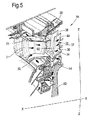
- Figure 5 shows an isometric view of a typical single stage cooled high-pressure turbine. Cooling air-flows are indicated by arrows.
- High-pressure turbine nozzle guide vanes 31 consume the greatest amount of cooling air on high temperature engines.
- High-pressure blades 32 typically use about half of the NGV coolant flow.
- the intermediate-pressure and low-pressure stages downstream of the HP turbine use progressively less cooling air.
- the high-pressure turbine airfoils are cooled by using high-pressure air from one of the compressors that has by-passed the combustor and is therefore relatively cool compared to the gas temperature.
- Typical cooling air temperatures are between 800 and 1000 K, while gas temperatures can be in excess of 2100 K.
- the cooling air from the compressor that is used to cool the hot turbine components is not used fully to extract work from the turbine. Therefore, as extracting coolant flow has an adverse effect on the engine operating efficiency, it is important to use the cooling air effectively.
- a turbine blade 32 has a longitudinally extending aerofoil portion 36 with facing suction side 37 and pressure side 38 walls.
- the aerofoil portion 36 extends across the working gas annulus, with the longitudinal direction of the aerofoil portion being generally along a radial direction relative to the engine's rotational axis XX.
- the turbine blade 32 has a root portion 44 radially inward of the aerofoil and a tip portion 46 radially outward of the aerofoil.
- the suction side 37 and side 38 walls meet at a leading edge 48 and a trailing edge 50.
- the root portion engages a rotor disc 52 via complimentary dovetail or in this example, fir-tree fixtures 54.
- Radially outward of the tip portion 46 is the casing shroud 35.
- the blade, disc and casing shroud form a rotor stage 56.
- a multi-pass cooling passage 38 is fed cooling air 42 by a feed passage 40 at a root of the blade.
- a second cooling air feed can supply additional coolant for the trailing edge of the blade.
- the trailing edge can be particularly prone to thermal erosion because it is relatively thin with a high surface area / volume and it is difficult to supply coolant.
- Cooling air leaves the multi-pass cooling passage through effusion holes 62, 64 in the aerofoil surfaces and particularly in the leading and trailing edges 48, 50 of the blade to create a film of cooling air over the surfaces 37, 38.
- the block arrows in Figure 5 show the general direction of cooling air flow.
- a casing 35 Radially outwardly of the turbine blade is a casing 35 often in the form of an annular array of shroud segments.
- the casing and a (radially) outer surface 68 of the blade tip define a gap or clearance 66.
- the casing may incorporate a tip clearance control arrangement capable of cooling or heating the shroud segment 35 to dilate or contract the shroud segments to maintain a desired position and gap relative to the blade tip.
- cooling or heating fluid can be fed via holes to impinge onto the shroud segment.
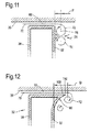
- FIG 11 is an enlarged schematic section similar to section E-E in Figure 6 , but showing a conventional blade tip configuration.
- An over-tip leakage flow 70 leaves the gap 66 and forms an OTL vortex 72 immediately next to the suction side wall 37.
- the working gas passing between circumferentially adjacent blades forms at least one passage vortex 74 radially inward of the OTL vortex 72 and immediately next to the suction side wall 37.
- the OTL vortex 72 has a rotational centre-line 76 which is a distance P away from the suction side wall.
- the OTL vortex 72 causes a three-dimensional impingement on the suction side wall and imparts heat into the wall.
- the passage vortex 74 alone or in combination with the OTL vortex 72 entrains further hot gases 78 from the passage and which impinge against the suction side wall and imparts yet further heat into the wall.
- This undesirable heat transfer can be amplified by the two vortices counter rotating and drawing hot working gases in to impinge on the suction side wall. This phenomenon can occur along some, most or all of the suction side wall.
- FIG 12 is an enlarged schematic section E-E of the tip region of the blade of Figure 6 .
- the blade 32 has an overhang 80 formed by the suction side wall. The configuration of the overhang 80 will be described in more detail later.
- the configuration of the overhang 80 is advantageous because at and near to leading edge, the OTL flow around the leading edge portion of the blade tip is subsonic, so putting an overhang in this leading edge portion reduces the overall OTL driving pressure and hence reduces the leakage mass flow through the tip.
- the distance of the OTL vortex 72 is now further away from suction side wall can be controlled by the configuration of the overhang and in particular any one or more of the overhang's parameters including its chord-wise location, the depth of the overhang and the width of the bump.
- the overhang reduces the secondary flow losses in the blade passage and the heat transfer to the blade suction surface near the tip.
- the OTL vortex 72 is now further away from the suction side wall, a distance Q which is greater than P.
- the overhang is configured to exploit an OTL flow region in which the flow chokes as it flows over the tip.
- the leakage mass flow rate in this region is therefore largely insensitive to moderate changes in back-pressure, and so there is minimal aerodynamic benefit to be gained by having an overhang on the rear portion of the blade. This also reduces the heat loading to the blade through a combination of reduced surface area exposed to hot gases and increased acceleration of OTL flow in the tip gap 66.
- the turbine blade 32 comprises the root portion 44, the platform 34 and the aerofoil 36.
- the aerofoil is mounted on the platform and is formed by the pressure side wall 38 and the suction side wall 37.
- the aerofoil extends radially outwardly towards the casing 35 and has a radially outer surface 66 which faces the casing.
- the casing 35 and the radially outer surface 66 define the gap 66.
- the pressure side wall 38 and the suction side wall 37 meet at nominal leading and trailing edges 48, 50.
- the nominal leading and trailing edges 48, 50 are the axially forward most part of the blade and the axially rearward most part of the blade.
- the pressure side wall 38 and the suction side wall 37 meet at a stagnation line 84.
- the stagnation line 84 is the position at which the working gas separates and travels either along the pressure or suction surfaces. However, the stagnation line can fluctuate in position relative to the geometric leading edge depending on radial height, engine power and specific blade design.
- the aerofoil has an axial chord length 82, which is defined as the axial distance from the geometric leading edge 48 to the geometric trailing edge 50.
- the suction side wall 37 defines part of the radially outer surface 68 of the aerofoil and the pressure side wall 38 can define the remainder of the radially outward surface 68.
- the suction side wall 37 is continuous from the platform 34 to the outer surface 68 and includes the overhang 80.
- the suction side surface 83 is also continuous from at least the platform 34 to the radially outer surface 68.
- the suction side wall 37 curves outwardly from the main part of the aerofoil into the overhang.
- the dotted line 88 defines the main part of the aerofoil immediately and radially inward of the overhang and as the suction surface begins to blend into the overhang.
- the overhang 80 has a length B and a maximum overhang length B max that is between 5% and 20% of the axial chord length 82 of the blade. It has been found for certain blades that the maximum overhang B max that is between 10% and 15% of the axial chord length is particularly effective.
- the maximum overhang length B max is located a distance A that is between 5% and 50% of the suction surface length from the (geometric) leading edge 48. It has been found for certain blades that the maximum overhang length B max is located between 15% and 40% of the suction surface length from the leading edge, which is particularly effective.
- the overhang 80 extends along (radially inwardly) the aerofoil a distance D (or depth) between 5% and 25% of the axial chord length 82 from the outer surface 68. It has been found for certain blades that the overhang extends along the aerofoil a distance between 10% and 20% of the axial chord length from the outer surface for a particularly effective response.
- the overhang 80 reduces in overhang length B from the maximum overhang length B max position towards the leading edge and towards the trailing edge.
- the overhang reduces in overhang length to zero at a position between 50% and 100% of the suction surface length from the leading edge.
- the maximum overhang length is located in the region where the OTL flow exiting the tip gap starts to roll into and form the OTL vortex.
- the overhang moves the tip gap exit away from the blade suction surface in this region and therefore causes the OTL vortex to displace away from the blade suction surface.
- the aerodynamic influence of the overhang in the leading edge region also reduces the size of the upper passage vortex and hence its subsequent interaction with the OTL vortex. Together these two effects reduce the impingement of hot gas onto the blade surface. This mechanism reduces the overall blade heat load despite the increase in surface area of the blade compared to un-shrouded blade having a flat tip as shown in Figure 1 .
- the presently described overhang also causes mixing of the OTL flow to occur further towards the pressure surface of the circumferentially adjacent blade.
- the aerodynamic loss caused by the mixing process is proportional to the cube of the velocity at which is occurs. Moving the OTL vortex towards the pressure surface of the adjacent blade exploits the cross passage velocity (pressure) gradient so that the OTL mixing occurs at a lower velocity, with reduced aerodynamic loss.
- the influence of the overhang on the structure of the vortices diminishes further towards the trailing edge of the blade.
- the present blade overhang with its location of the maximum overhang length, the size and chordal extent of the overhang advantageously improves aerodynamic efficiency and reduces heat load for a given blade.
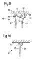
- Figures 8 , 9 and 10 show alternative configurations of a tip of a blade in accordance with the present invention.
- the overhang 80 is continuous around the leading edge 48 and extends around a part of the pressure side wall.
- the radially outer surface 68 defines a cavity 90.
- the cavity 90 can cause a tip vortex 92 to occur.
- the tip vortex 92 can help prevent over tip leakage. Only one cavity is shown however, more than one cavity can be formed in the radially outer surface 68.
- the cavity 92 further improves the sealing over the tip and also protects the floor of the cavity from the hot gases, thereby reducing the heat transfer into the blade and hence reducing cooling requirements.
- the overhang 80 may change in depth D as its overhang width B changes.
- the overhang may be defined by a constant radius or other compound curve.
- the overhang may include a straight section 108 defining part or all of the free edge of the overhang; alternatively the free edge may be defined by a radius 110.
- the straight section 108 or radius 110 extends between the suction side wall surface 86 and the outer surface 68. Aerofoil surfaces are complex geometric three-dimensional shapes and it is intended that the suction and pressure surfaces smoothly blend or transition into the overhang.
- the presently described turbine blade can be any one of a high pressure, intermediate pressure or low pressure turbine and equally applicable to an aero, marine or industrial turbine engine whether a gas or steam turbine engine.
- the presently described turbine blade can be any one of an engine having one, two or three spools.
- the presently described turbine blade is described with reference to including a multi-pass cooling passage 38 common in metallic components any form of cooling arrangement may be present and indeed no cooling arrangement need be present.
- the presently described turbine blade can be formed of metal, ceramic or a composite material.
Landscapes
- Engineering & Computer Science (AREA)
- Mechanical Engineering (AREA)
- General Engineering & Computer Science (AREA)
- Physics & Mathematics (AREA)
- Fluid Mechanics (AREA)
- Turbine Rotor Nozzle Sealing (AREA)
Abstract
Description
- The present invention relates to a blade of a turbine and preferably for a gas turbine engine, and in particular a structure of the tip of the blade.
- For turbine rotor blades and particularly high pressure (HP) turbine blades, there is an industry wide and ever-important objective to minimise both over-tip leakage (OTL) of hot working gases between a tip of the blades and a casing and heat transfer from the hot working gases to the blade. OTL occurs because of the pressure differential between a pressure-side and a suction-side of a turbine blade; this pressure differential can be referred to as 'driving pressure'.
- In general, there are three types of tip geometry configurations which attempt to minimise over tip leakage: un-shrouded, partially shrouded (or 'winglet') and fully shrouded. The simplest form of tip geometry is an un-shrouded type having a flat tip (see
Figure 1 ). A flat tip design is typically associated with a relatively high aerodynamic loss due to the over-tip leakage flow and high heat transfer, although it is relatively simple to manufacture. Other configurations have been developed with the main intent to reduce the over-tip leakage flow and losses. One such type is called a 'squealer' (Figure 2 ), which has pressure and suction walls sealed with a tip plate and ribs or fins extending from the tip plate to define a tip cavity. Another blade tip design is referred to as a 'winglet' (Figure 3 ), which is effectively a partially shrouded blade and also has ribs or fins extending towards the casing. - Both the squealer and winglet designs form a tip cavity that serve to avoid losses in efficiency by reducing the amount of leakage flow passing over the tip and reducing the flow disturbances set up by the leakage flow. The gas that passes over a pressure side fin of the cavity forms a vortex in the cavity. Whereas these blade designs help to prevent over-tip leakage, they both require substantial amounts of cooling air. In particular, the over-tip leakage forms a vortex which impinges on the suction side of the blade causing significant heat transfer. The amount of cooling is largely determined by the heat load on the blades the hot mainstream gases.
- The present invention therefore seeks to minimize over tip leakage and reduce heat load from the working gas into the blades.
- A turbine blade has a root portion, a platform and an aerofoil, the aerofoil is mounted on the platform and is formed by a pressure side wall and a suction side wall and has an outer surface, the pressure side wall and the suction side wall meet at a leading edge and a trailing edge, the aerofoil has an axial chord length, the suction side wall defines part of the radially outward surface of the aerofoil, the suction side wall defines an overhang, the overhang has a maximum overhang length that is between 5% and 20% of the axial chord length of the blade and is located between 15% and 40% of the suction surface length from the leading edge and reduces in overhang length to zero at a position between 50% and 100% of the suction surface length from the leading edge.
- The overhang may extend along the aerofoil a distance between 5% and 25% of the axial chord length from the outer surface.
- The overhang may extend along the aerofoil a distance between 10% and 20% of the axial chord length from the outer surface.
- The overhang may have a maximum overhang that is between 10% and 15% of the axial chord length of the blade
- The maximum overhang may be located between 25% and 40% of the suction surface length from the leading edge.
- The overhang may reduce in overhang length from the maximum overhang length towards the leading edge and towards the trailing edge.
- The overhang may reduce in overhang length to zero at a position between 50% and 100% of the suction surface length from the leading edge.
- In another aspect of a rotor stage of a turbine comprising a rotational axis, a shroud and radially inward thereof a turbine blade in accordance with the above paragraphs, and a clearance gap which is defined from the radially outward surface to the shroud.
-
-
Figure 1 is a view on the pressure-side of a tip portion of a known turbine blade having a flat tip surface, -
Figure 2 is a view on the pressure-side of a tip portion of a known turbine blade having a squealer tip configuration, -
Figure 3 is a view on the suction-side of a tip portion of a known turbine blade having a winglet tip configuration, -
Figure 4 is a schematic longitudinal cross-section through a ducted fan gas turbine engine in which the present invention is incorporated, -
Figure 5 is an isometric view of a typical single stage cooled turbine of the gas turbine described with reference toFigure 4 , -
Figure 6 is a schematic plan view of a tip of a blade in accordance with the present invention, -
Figure 7 is a schematic section E-E of the blade ofFigure 6 , -
Figure 8 is a schematic plan view of alternative configurations of a tip of a blade in accordance with the present invention, -
Figure 9 is a schematic section F-F of the blade ofFigure 8 , -
Figure 10 is a schematic section G-G of the blade ofFigure 8 , -
Figure 11 is an enlarged schematic section similar to section E-E inFigure 6 , but showing a conventional blade configuration, -
Figure 12 is an enlarged schematic section E-E of the tip region of the blade ofFigure 6 in accordance with the present invention, and -
Figures 13-17 are views of a number of different embodiments of a tip region of a blade in accordance with the present invention. - With reference to
Figure 4 , a ducted fan gas turbine engine generally indicated at 10 has a principal and rotational axis X-X. The engine comprises, in axial flow series, anair intake 11, apropulsive fan 12, anintermediate pressure compressor 13, a high-pressure compressor 14,combustion equipment 15, a high-pressure turbine 16, andintermediate pressure turbine 17, a low-pressure turbine 18 and a coreengine exhaust nozzle 19. Anacelle 21 generally surrounds theengine 10 and defines theintake 11, abypass duct 22 and abypass exhaust nozzle 23. - The
gas turbine engine 10 works in a conventional manner so that air entering theintake 11 is accelerated by thefan 12 to produce two air flows: afirst air flow 8 into theintermediate pressure compressor 13 and a second air flow 9 which passes through thebypass duct 22 to provide propulsive thrust. Theintermediate pressure compressor 13 compresses theair flow 8 directed into it before delivering that air to thehigh pressure compressor 14 where further compression takes place. - The compressed air exhausted from the high-
pressure compressor 14 is directed into thecombustion equipment 15 where it is mixed with fuel and the mixture combusted. The resultant hot combustion products then expand through, and thereby drive the high, intermediate and low-pressure turbines nozzle 19 to provide additional propulsive thrust. The high, intermediate and low-pressure turbines respectively drive the high andintermediate pressure compressors fan 12 by suitable interconnecting shafts. - The performance of gas turbine engines, whether measured in terms of efficiency or specific output, is improved by increasing the turbine gas temperature. It is therefore desirable to operate the turbines at the highest possible temperatures. For any engine cycle compression ratio or bypass ratio, increasing the turbine entry gas temperature produces more specific thrust (e.g. engine thrust per unit of air mass flow). However as turbine entry temperatures increase, the life of an un-cooled turbine falls, necessitating the development of better materials and the introduction of internal air cooling.
- In modern engines, the high-pressure turbine gas temperatures are hotter than the melting point of the material of the blades and vanes, necessitating internal air-cooling of these airfoil components. During its passage through the engine, the mean temperature of the gas stream decreases as power is extracted. Therefore, the need to cool the static and rotary parts of the engine structure decreases as the gas moves from the high-pressure stage(s), through the intermediate-pressure and low-pressure stages, and towards the exit nozzle.
-
Figure 5 shows an isometric view of a typical single stage cooled high-pressure turbine. Cooling air-flows are indicated by arrows. - Internal convection and external coolant films are the prime methods of cooling the gas path components -
airfoils 36,platforms 34,shrouds 33 andcasing shroud segments 35. High-pressure turbine nozzle guide vanes 31 (NGVs) consume the greatest amount of cooling air on high temperature engines. High-pressure blades 32 typically use about half of the NGV coolant flow. The intermediate-pressure and low-pressure stages downstream of the HP turbine use progressively less cooling air. - The high-pressure turbine airfoils are cooled by using high-pressure air from one of the compressors that has by-passed the combustor and is therefore relatively cool compared to the gas temperature. Typical cooling air temperatures are between 800 and 1000 K, while gas temperatures can be in excess of 2100 K.
- The cooling air from the compressor that is used to cool the hot turbine components is not used fully to extract work from the turbine. Therefore, as extracting coolant flow has an adverse effect on the engine operating efficiency, it is important to use the cooling air effectively.
- Ever increasing gas temperature levels combined with a drive towards flatter combustion radial temperature profiles, in the interests of reduced combustor emissions, have resulted in an increase in local gas temperature experienced by the extremities of the blades and vanes, and the working gas annulus endwalls.
- Referring to
Figures 5 ,6 and 7 , aturbine blade 32 has a longitudinally extendingaerofoil portion 36 with facingsuction side 37 andpressure side 38 walls. Theaerofoil portion 36 extends across the working gas annulus, with the longitudinal direction of the aerofoil portion being generally along a radial direction relative to the engine's rotational axis XX. Theturbine blade 32 has aroot portion 44 radially inward of the aerofoil and atip portion 46 radially outward of the aerofoil. Thesuction side 37 andside 38 walls meet at aleading edge 48 and a trailingedge 50. The root portion engages arotor disc 52 via complimentary dovetail or in this example, fir-tree fixtures 54. Radially outward of thetip portion 46 is thecasing shroud 35. The blade, disc and casing shroud form arotor stage 56. - A
multi-pass cooling passage 38 is fed coolingair 42 by afeed passage 40 at a root of the blade. A second cooling air feed can supply additional coolant for the trailing edge of the blade. The trailing edge can be particularly prone to thermal erosion because it is relatively thin with a high surface area / volume and it is difficult to supply coolant. Cooling air leaves the multi-pass cooling passage through effusion holes 62, 64 in the aerofoil surfaces and particularly in the leading and trailingedges surfaces Figure 5 show the general direction of cooling air flow. - Radially outwardly of the turbine blade is a
casing 35 often in the form of an annular array of shroud segments. The casing and a (radially)outer surface 68 of the blade tip define a gap orclearance 66. The casing may incorporate a tip clearance control arrangement capable of cooling or heating theshroud segment 35 to dilate or contract the shroud segments to maintain a desired position and gap relative to the blade tip. As is well known in the tip clearance control field cooling or heating fluid can be fed via holes to impinge onto the shroud segment. -
Figure 11 is an enlarged schematic section similar to section E-E inFigure 6 , but showing a conventional blade tip configuration. Anover-tip leakage flow 70 leaves thegap 66 and forms anOTL vortex 72 immediately next to thesuction side wall 37. The working gas passing between circumferentially adjacent blades forms at least onepassage vortex 74 radially inward of theOTL vortex 72 and immediately next to thesuction side wall 37. For descriptive purposes theOTL vortex 72 has a rotational centre-line 76 which is a distance P away from the suction side wall. TheOTL vortex 72 causes a three-dimensional impingement on the suction side wall and imparts heat into the wall. In addition, thepassage vortex 74 alone or in combination with theOTL vortex 72 entrains furtherhot gases 78 from the passage and which impinge against the suction side wall and imparts yet further heat into the wall. This undesirable heat transfer can be amplified by the two vortices counter rotating and drawing hot working gases in to impinge on the suction side wall. This phenomenon can occur along some, most or all of the suction side wall. - Referring to
Figure 12 which is an enlarged schematic section E-E of the tip region of the blade ofFigure 6 . Theblade 32 has anoverhang 80 formed by the suction side wall. The configuration of theoverhang 80 will be described in more detail later. - The configuration of the
overhang 80 is advantageous because at and near to leading edge, the OTL flow around the leading edge portion of the blade tip is subsonic, so putting an overhang in this leading edge portion reduces the overall OTL driving pressure and hence reduces the leakage mass flow through the tip. The distance of theOTL vortex 72 is now further away from suction side wall can be controlled by the configuration of the overhang and in particular any one or more of the overhang's parameters including its chord-wise location, the depth of the overhang and the width of the bump. The overhang reduces the secondary flow losses in the blade passage and the heat transfer to the blade suction surface near the tip. Thus theOTL vortex 72 is now further away from the suction side wall, a distance Q which is greater than P. - The overhang is configured to exploit an OTL flow region in which the flow chokes as it flows over the tip. The leakage mass flow rate in this region is therefore largely insensitive to moderate changes in back-pressure, and so there is minimal aerodynamic benefit to be gained by having an overhang on the rear portion of the blade. This also reduces the heat loading to the blade through a combination of reduced surface area exposed to hot gases and increased acceleration of OTL flow in the
tip gap 66. - Referring again to
Figures 6 and 7 the configuration of theoverhang 80 is now described in more detail. Theturbine blade 32 comprises theroot portion 44, theplatform 34 and theaerofoil 36. The aerofoil is mounted on the platform and is formed by thepressure side wall 38 and thesuction side wall 37. The aerofoil extends radially outwardly towards thecasing 35 and has a radiallyouter surface 66 which faces the casing. Thecasing 35 and the radiallyouter surface 66 define thegap 66. - The
pressure side wall 38 and thesuction side wall 37 meet at nominal leading and trailingedges edges pressure side wall 38 and thesuction side wall 37 meet at astagnation line 84. Thestagnation line 84 is the position at which the working gas separates and travels either along the pressure or suction surfaces. However, the stagnation line can fluctuate in position relative to the geometric leading edge depending on radial height, engine power and specific blade design. - The aerofoil has an
axial chord length 82, which is defined as the axial distance from the geometric leadingedge 48 to the geometric trailingedge 50. - The
suction side wall 37 defines part of the radiallyouter surface 68 of the aerofoil and thepressure side wall 38 can define the remainder of the radiallyoutward surface 68. - The
suction side wall 37 is continuous from theplatform 34 to theouter surface 68 and includes theoverhang 80. Thus the suction side surface 83 is also continuous from at least theplatform 34 to the radiallyouter surface 68. Thesuction side wall 37 curves outwardly from the main part of the aerofoil into the overhang. The dottedline 88 defines the main part of the aerofoil immediately and radially inward of the overhang and as the suction surface begins to blend into the overhang. - The
overhang 80 has a length B and a maximum overhang length Bmax that is between 5% and 20% of theaxial chord length 82 of the blade. It has been found for certain blades that the maximum overhang Bmax that is between 10% and 15% of the axial chord length is particularly effective. The maximum overhang length Bmax is located a distance A that is between 5% and 50% of the suction surface length from the (geometric) leadingedge 48. It has been found for certain blades that the maximum overhang length Bmax is located between 15% and 40% of the suction surface length from the leading edge, which is particularly effective. - In this example, the
overhang 80 extends along (radially inwardly) the aerofoil a distance D (or depth) between 5% and 25% of theaxial chord length 82 from theouter surface 68. It has been found for certain blades that the overhang extends along the aerofoil a distance between 10% and 20% of the axial chord length from the outer surface for a particularly effective response. - The
overhang 80 reduces in overhang length B from the maximum overhang length Bmax position towards the leading edge and towards the trailing edge. In theFigure 6 example, the overhang reduces in overhang length to zero at a position between 50% and 100% of the suction surface length from the leading edge. - The maximum overhang length is located in the region where the OTL flow exiting the tip gap starts to roll into and form the OTL vortex. The overhang moves the tip gap exit away from the blade suction surface in this region and therefore causes the OTL vortex to displace away from the blade suction surface. The aerodynamic influence of the overhang in the leading edge region also reduces the size of the upper passage vortex and hence its subsequent interaction with the OTL vortex. Together these two effects reduce the impingement of hot gas onto the blade surface. This mechanism reduces the overall blade heat load despite the increase in surface area of the blade compared to un-shrouded blade having a flat tip as shown in
Figure 1 . - The presently described overhang also causes mixing of the OTL flow to occur further towards the pressure surface of the circumferentially adjacent blade. The aerodynamic loss caused by the mixing process is proportional to the cube of the velocity at which is occurs. Moving the OTL vortex towards the pressure surface of the adjacent blade exploits the cross passage velocity (pressure) gradient so that the OTL mixing occurs at a lower velocity, with reduced aerodynamic loss.
- In both cases, the influence of the overhang on the structure of the vortices diminishes further towards the trailing edge of the blade. As such, the present blade overhang with its location of the maximum overhang length, the size and chordal extent of the overhang advantageously improves aerodynamic efficiency and reduces heat load for a given blade.
-
Figures 8 ,9 and 10 show alternative configurations of a tip of a blade in accordance with the present invention. In this example, theoverhang 80 is continuous around the leadingedge 48 and extends around a part of the pressure side wall. The radiallyouter surface 68 defines acavity 90. Thecavity 90 can cause atip vortex 92 to occur. Thetip vortex 92 can help prevent over tip leakage. Only one cavity is shown however, more than one cavity can be formed in the radiallyouter surface 68. - The
cavity 92 further improves the sealing over the tip and also protects the floor of the cavity from the hot gases, thereby reducing the heat transfer into the blade and hence reducing cooling requirements. -
Figure 13 is an axially forward view of the tip of theblade 32 having acavity 92 completely bounded by the pressure andsuction side walls -
Figure 14 is an axially forward looking view of the tip of theblade 32 having acavity 92 bounded by the pressure andsuction side walls opening 94 is formed. Theopening 94 can be positioned close to the geometric leadingedge 48 or thestagnation line 84. Theopening 94 allows aportion 96 of the working gas into thecavity 92 which forces theOTL leakage flow 100 to exit the cavity at arearward part 102 of the blade as shown byarrow 98. -
Figure 15 is an axially forward looking view of the tip of theblade 32 having acavity 92 bounded by the pressure andsuction side walls opening 95 is formed. Theopening 95 allows theOTL gas flow 100 to exit the cavity rather than spilling over onto the suction side wall. -
Figure 16 is an axially forward looking view of the tip of theblade 32 having acavity 92 bounded by the pressure andsuction side walls opening 95 is formed by curtailing thepressure side wall 38 short (104) of the trailingedge 102 of the suction side wall. Internal coolant can be channelled to egress the blade interior and form a coolant film of the now exposed inner wall of the suction surface wall to protect the trailing edge of the blade. Coolant may also be exhausted through an array ofcooling holes 106 in thecavity 92, thus cooling the OTL flow. Theopening 95 allows theOTL gas flow 100 to exit the cavity rather than spilling over onto the suction side wall. -
Figure 17 is an axially forward looking view of the tip of theblade 32 having acavity 92 bounded by the pressure andsuction side walls openings Figures 14 and15 . Again the objective of the openings is to force the over tip leakage rearwardly and prevent the over tip leakage from spilling over on to the suction surface. - It will be appreciated that the
overhang 80 may change in depth D as its overhang width B changes. The overhang may be defined by a constant radius or other compound curve. The overhang may include astraight section 108 defining part or all of the free edge of the overhang; alternatively the free edge may be defined by aradius 110. Thestraight section 108 orradius 110 extends between the suctionside wall surface 86 and theouter surface 68. Aerofoil surfaces are complex geometric three-dimensional shapes and it is intended that the suction and pressure surfaces smoothly blend or transition into the overhang. - The presently described turbine blade can be any one of a high pressure, intermediate pressure or low pressure turbine and equally applicable to an aero, marine or industrial turbine engine whether a gas or steam turbine engine. The presently described turbine blade can be any one of an engine having one, two or three spools.
- Although the presently described turbine blade is described with reference to including a
multi-pass cooling passage 38 common in metallic components any form of cooling arrangement may be present and indeed no cooling arrangement need be present. The presently described turbine blade can be formed of metal, ceramic or a composite material.
Claims (6)
the aerofoil is mounted on the platform and is formed by a pressure side wall (38) and a suction side wall (37) and has an outer surface (68),
the pressure side wall (38) and the suction side wall (37) meet at a leading edge (48) and a trailing edge (50),
the aerofoil has an aerofoil tip and an axial chord length (82),
the suction side wall (37) defines part of the radially outward surface (68) of the aerofoil,
the suction side wall defines an overhang (80) at the aerofoil tip,
the overhang has a maximum overhang length (B) that is between 5% and 20% of the axial chord length of the blade and is located between 15% and 40% of the suction surface length from the leading edge and reduces in overhang length to zero at a position between 50% and 100% of the suction surface length from the leading edge.
a rotational axis (XX),
a shroud (35) and radially inward thereof
a turbine blade (32) in accordance with claim 1,
a clearance gap (66) which is defined from the radially outward surface to the shroud.
Applications Claiming Priority (2)
| Application Number | Priority Date | Filing Date | Title |
|---|---|---|---|
| GB201219267A GB201219267D0 (en) | 2012-10-26 | 2012-10-26 | Turbine blade |
| DE201210021400 DE102012021400A1 (en) | 2012-10-31 | 2012-10-31 | Turbine rotor blade of gas turbine engine, has overhang which is provided at stagnation point, when intersection point is zero, so that maximum value of barrel length of suction-side overhang is at about specific percentage |
Publications (2)
| Publication Number | Publication Date |
|---|---|
| EP2725195A1 true EP2725195A1 (en) | 2014-04-30 |
| EP2725195B1 EP2725195B1 (en) | 2019-09-25 |
Family
ID=49448046
Family Applications (2)
| Application Number | Title | Priority Date | Filing Date |
|---|---|---|---|
| EP13190039.1A Active EP2725195B1 (en) | 2012-10-26 | 2013-10-24 | Turbine blade and corresponding rotor stage |
| EP13190022.7A Active EP2725194B1 (en) | 2012-10-26 | 2013-10-24 | Turbine rotor blade of a gas turbine |
Family Applications After (1)
| Application Number | Title | Priority Date | Filing Date |
|---|---|---|---|
| EP13190022.7A Active EP2725194B1 (en) | 2012-10-26 | 2013-10-24 | Turbine rotor blade of a gas turbine |
Country Status (2)
| Country | Link |
|---|---|
| US (2) | US10641107B2 (en) |
| EP (2) | EP2725195B1 (en) |
Cited By (3)
| Publication number | Priority date | Publication date | Assignee | Title |
|---|---|---|---|---|
| CN105317468A (en) * | 2014-05-29 | 2016-02-10 | 通用电气公司 | Rotor blade cooling flow |
| EP2987956A1 (en) | 2014-08-18 | 2016-02-24 | Siemens Aktiengesellschaft | Compressor aerofoil |
| EP3061914B1 (en) * | 2015-02-25 | 2024-01-03 | General Electric Technology GmbH | Turbine rotor blade and gas turbine engine |
Families Citing this family (24)
| Publication number | Priority date | Publication date | Assignee | Title |
|---|---|---|---|---|
| EP2725195B1 (en) | 2012-10-26 | 2019-09-25 | Rolls-Royce plc | Turbine blade and corresponding rotor stage |
| US9638041B2 (en) | 2013-10-23 | 2017-05-02 | General Electric Company | Turbine bucket having non-axisymmetric base contour |
| US9551226B2 (en) | 2013-10-23 | 2017-01-24 | General Electric Company | Turbine bucket with endwall contour and airfoil profile |
| US9670784B2 (en) | 2013-10-23 | 2017-06-06 | General Electric Company | Turbine bucket base having serpentine cooling passage with leading edge cooling |
| US20150110617A1 (en) * | 2013-10-23 | 2015-04-23 | General Electric Company | Turbine airfoil including tip fillet |
| US9528379B2 (en) | 2013-10-23 | 2016-12-27 | General Electric Company | Turbine bucket having serpentine core |
| US9797258B2 (en) | 2013-10-23 | 2017-10-24 | General Electric Company | Turbine bucket including cooling passage with turn |
| US10508549B2 (en) * | 2014-06-06 | 2019-12-17 | United Technologies Corporation | Gas turbine engine airfoil with large thickness properties |
| EP2977548B1 (en) * | 2014-07-22 | 2021-03-10 | Safran Aero Boosters SA | Blade and corresponding turbomachine |
| EP2977549B1 (en) * | 2014-07-22 | 2017-05-31 | Safran Aero Boosters SA | Axial turbomachine blading and corresponding turbomachine |
| US9995166B2 (en) | 2014-11-21 | 2018-06-12 | General Electric Company | Turbomachine including a vane and method of assembling such turbomachine |
| US10107108B2 (en) | 2015-04-29 | 2018-10-23 | General Electric Company | Rotor blade having a flared tip |
| FR3043715B1 (en) * | 2015-11-16 | 2020-11-06 | Snecma | TURBINE VANE INCLUDING A BLADE WITH A TUB WITH A CURVED INTRADOS IN THE PALE TOP REGION |
| US10253637B2 (en) * | 2015-12-11 | 2019-04-09 | General Electric Company | Method and system for improving turbine blade performance |
| FR3055698B1 (en) * | 2016-09-08 | 2018-08-17 | Safran Aircraft Engines | METHOD FOR CONTROLLING THE CONFORMITY OF THE PROFILE OF A CURVED SURFACE OF AN ELEMENT OF A TURBOMACHINE |
| JP6871770B2 (en) * | 2017-03-17 | 2021-05-12 | 三菱重工業株式会社 | Turbine blades and gas turbines |
| EP3421725A1 (en) * | 2017-06-26 | 2019-01-02 | Siemens Aktiengesellschaft | Compressor aerofoil |
| WO2019035800A1 (en) * | 2017-08-14 | 2019-02-21 | Siemens Aktiengesellschaft | Turbine blades |
| EP3477059A1 (en) * | 2017-10-26 | 2019-05-01 | Siemens Aktiengesellschaft | Compressor aerofoil |
| GB201719538D0 (en) * | 2017-11-24 | 2018-01-10 | Rolls Royce Plc | Gas turbine engine |
| US11118462B2 (en) * | 2019-01-24 | 2021-09-14 | Pratt & Whitney Canada Corp. | Blade tip pocket rib |
| US11066935B1 (en) | 2020-03-20 | 2021-07-20 | General Electric Company | Rotor blade airfoil |
| US11371359B2 (en) | 2020-11-26 | 2022-06-28 | Pratt & Whitney Canada Corp. | Turbine blade for a gas turbine engine |
| US12228034B2 (en) * | 2022-04-28 | 2025-02-18 | Hamilton Sundstrand Corporation | Additively manufactures multi-metallic adaptive or abradable rotor tip seals |
Citations (2)
| Publication number | Priority date | Publication date | Assignee | Title |
|---|---|---|---|---|
| GB1491556A (en) * | 1974-02-02 | 1977-11-09 | Mtu Muenchen Gmbh | Rotor blades for turbomachines |
| EP1898052A2 (en) * | 2006-08-21 | 2008-03-12 | General Electric Company | Flared tip turbine blade |
Family Cites Families (31)
| Publication number | Priority date | Publication date | Assignee | Title |
|---|---|---|---|---|
| US711832A (en) | 1902-06-26 | 1902-10-21 | Lester C Denison | Adjustable side bearing for cars. |
| US1955929A (en) * | 1932-03-18 | 1934-04-24 | Voith Gmbh J M | Impeller |
| GB793143A (en) | 1956-05-17 | 1958-04-09 | Daimler Benz Ag | Improvements relating to axial-flow compressors |
| US3706512A (en) | 1970-11-16 | 1972-12-19 | United Aircraft Canada | Compressor blades |
| GB1366024A (en) | 1972-11-28 | 1974-09-04 | Levy J | Colouring process for photographic prints |
| US4424001A (en) * | 1981-12-04 | 1984-01-03 | Westinghouse Electric Corp. | Tip structure for cooled turbine rotor blade |
| US4761116A (en) * | 1987-05-11 | 1988-08-02 | General Electric Company | Turbine blade with tip vent |
| US5503527A (en) | 1994-12-19 | 1996-04-02 | General Electric Company | Turbine blade having tip slot |
| GB9607578D0 (en) | 1996-04-12 | 1996-06-12 | Rolls Royce Plc | Turbine rotor blades |
| US6422821B1 (en) | 2001-01-09 | 2002-07-23 | General Electric Company | Method and apparatus for reducing turbine blade tip temperatures |
| GB2409006B (en) | 2003-12-11 | 2006-05-17 | Rolls Royce Plc | Tip sealing for a turbine rotor blade |
| GB2413160B (en) | 2004-04-17 | 2006-08-09 | Rolls Royce Plc | Turbine rotor blades |
| EP1591624A1 (en) | 2004-04-27 | 2005-11-02 | Siemens Aktiengesellschaft | Compressor blade and compressor. |
| GB0503185D0 (en) | 2005-02-16 | 2005-03-23 | Rolls Royce Plc | A turbine blade |
| FR2885645A1 (en) * | 2005-05-13 | 2006-11-17 | Snecma Moteurs Sa | Hollow rotor blade for high pressure turbine, has pressure side wall presenting projecting end portion with tip that lies in outside face of end wall such that cooling channels open out into pressure side wall in front of cavity |
| EP1977083A1 (en) | 2006-01-13 | 2008-10-08 | ETH Zürich | Turbine blade with recessed tip |
| US20070237627A1 (en) | 2006-03-31 | 2007-10-11 | Bunker Ronald S | Offset blade tip chord sealing system and method for rotary machines |
| US7740445B1 (en) | 2007-06-21 | 2010-06-22 | Florida Turbine Technologies, Inc. | Turbine blade with near wall cooling |
| GB0724612D0 (en) | 2007-12-19 | 2008-01-30 | Rolls Royce Plc | Rotor blades |
| CN101255873B (en) | 2008-02-28 | 2010-06-09 | 大连海事大学 | compressor motor blade tip winglet |
| CN101255800B (en) | 2008-02-28 | 2010-06-09 | 大连海事大学 | Turbine or steam turbine rotor blade tip winglet |
| GB0813556D0 (en) | 2008-07-24 | 2008-09-03 | Rolls Royce Plc | A blade for a rotor |
| GB0815957D0 (en) | 2008-09-03 | 2008-10-08 | Rolls Royce Plc | Blades |
| GB201006451D0 (en) * | 2010-04-19 | 2010-06-02 | Rolls Royce Plc | Blades |
| GB201006449D0 (en) * | 2010-04-19 | 2010-06-02 | Rolls Royce Plc | Blades |
| GB201006450D0 (en) | 2010-04-19 | 2010-06-02 | Rolls Royce Plc | Blades |
| US8944774B2 (en) * | 2012-01-03 | 2015-02-03 | General Electric Company | Gas turbine nozzle with a flow fence |
| EP2725195B1 (en) * | 2012-10-26 | 2019-09-25 | Rolls-Royce plc | Turbine blade and corresponding rotor stage |
| US20140241899A1 (en) * | 2013-02-25 | 2014-08-28 | Pratt & Whitney Canada Corp. | Blade leading edge tip rib |
| US20150110617A1 (en) | 2013-10-23 | 2015-04-23 | General Electric Company | Turbine airfoil including tip fillet |
| DE102013224998A1 (en) | 2013-12-05 | 2015-06-11 | Rolls-Royce Deutschland Ltd & Co Kg | Turbine rotor blade of a gas turbine and method for cooling a blade tip of a turbine rotor blade of a gas turbine |
-
2013
- 2013-10-24 EP EP13190039.1A patent/EP2725195B1/en active Active
- 2013-10-24 US US14/062,230 patent/US10641107B2/en active Active
- 2013-10-24 EP EP13190022.7A patent/EP2725194B1/en active Active
- 2013-10-24 US US14/061,971 patent/US9593584B2/en active Active
Patent Citations (2)
| Publication number | Priority date | Publication date | Assignee | Title |
|---|---|---|---|---|
| GB1491556A (en) * | 1974-02-02 | 1977-11-09 | Mtu Muenchen Gmbh | Rotor blades for turbomachines |
| EP1898052A2 (en) * | 2006-08-21 | 2008-03-12 | General Electric Company | Flared tip turbine blade |
Cited By (7)
| Publication number | Priority date | Publication date | Assignee | Title |
|---|---|---|---|---|
| CN105317468A (en) * | 2014-05-29 | 2016-02-10 | 通用电气公司 | Rotor blade cooling flow |
| EP2987956A1 (en) | 2014-08-18 | 2016-02-24 | Siemens Aktiengesellschaft | Compressor aerofoil |
| WO2016026814A1 (en) * | 2014-08-18 | 2016-02-25 | Siemens Aktiengesellschaft | Compressor aerofoil |
| CN106574509A (en) * | 2014-08-18 | 2017-04-19 | 西门子股份公司 | Compressor aerofoil |
| CN106574509B (en) * | 2014-08-18 | 2019-09-13 | 西门子股份公司 | Compressor airfoil |
| US10458427B2 (en) | 2014-08-18 | 2019-10-29 | Siemens Aktiengesellschaft | Compressor aerofoil |
| EP3061914B1 (en) * | 2015-02-25 | 2024-01-03 | General Electric Technology GmbH | Turbine rotor blade and gas turbine engine |
Also Published As
| Publication number | Publication date |
|---|---|
| US10641107B2 (en) | 2020-05-05 |
| EP2725194B1 (en) | 2020-02-19 |
| EP2725195B1 (en) | 2019-09-25 |
| US9593584B2 (en) | 2017-03-14 |
| US20140119942A1 (en) | 2014-05-01 |
| US20140119920A1 (en) | 2014-05-01 |
| EP2725194A1 (en) | 2014-04-30 |
Similar Documents
| Publication | Publication Date | Title |
|---|---|---|
| EP2725195B1 (en) | Turbine blade and corresponding rotor stage | |
| EP2489838B1 (en) | Cooled component for the turbine of a gas turbine engine | |
| EP2746536A1 (en) | Rotor stage of a turbine | |
| EP2235328B1 (en) | Blade cooling | |
| US7632062B2 (en) | Turbine rotor blades | |
| CN107013248B (en) | Method and system for improving turbine blade performance | |
| US9228442B2 (en) | Turbine airfoil tip shelf and squealer pocket cooling | |
| CA2596777C (en) | Conformal tip baffle airfoil | |
| GB2498551A (en) | Cooled aerofoil with helical passage | |
| US11466579B2 (en) | Turbine engine airfoil and method | |
| US9382811B2 (en) | Aerofoil cooling arrangement | |
| EP0670953A1 (en) | Coolable airfoil structure | |
| US8297925B2 (en) | Aerofoil configuration | |
| EP2980357A1 (en) | Gas turbine aerofoil trailing edge | |
| US9376918B2 (en) | Aerofoil cooling arrangement | |
| EP2604795B1 (en) | Aerofoil blade or vane | |
| EP3418494B1 (en) | Secondary flow control | |
| EP4553284A1 (en) | Turbine engine with a blade assembly having cooling holes | |
| US12378889B2 (en) | Turbine engine with a blade assembly having cooling conduits | |
| US20250283414A1 (en) | Turbine engine with a blade assembly having a set of cooling conduits |
Legal Events
| Date | Code | Title | Description |
|---|---|---|---|
| PUAI | Public reference made under article 153(3) epc to a published international application that has entered the european phase |
Free format text: ORIGINAL CODE: 0009012 |
|
| 17P | Request for examination filed |
Effective date: 20131024 |
|
| AK | Designated contracting states |
Kind code of ref document: A1 Designated state(s): AL AT BE BG CH CY CZ DE DK EE ES FI FR GB GR HR HU IE IS IT LI LT LU LV MC MK MT NL NO PL PT RO RS SE SI SK SM TR |
|
| AX | Request for extension of the european patent |
Extension state: BA ME |
|
| 17P | Request for examination filed |
Effective date: 20141028 |
|
| RBV | Designated contracting states (corrected) |
Designated state(s): AL AT BE BG CH CY CZ DE DK EE ES FI FR GB GR HR HU IE IS IT LI LT LU LV MC MK MT NL NO PL PT RO RS SE SI SK SM TR |
|
| RAP1 | Party data changed (applicant data changed or rights of an application transferred) |
Owner name: ROLLS-ROYCE DEUTSCHLAND LTD & CO KG Owner name: ROLLS-ROYCE PLC |
|
| GRAP | Despatch of communication of intention to grant a patent |
Free format text: ORIGINAL CODE: EPIDOSNIGR1 |
|
| STAA | Information on the status of an ep patent application or granted ep patent |
Free format text: STATUS: GRANT OF PATENT IS INTENDED |
|
| INTG | Intention to grant announced |
Effective date: 20190716 |
|
| GRAS | Grant fee paid |
Free format text: ORIGINAL CODE: EPIDOSNIGR3 |
|
| GRAA | (expected) grant |
Free format text: ORIGINAL CODE: 0009210 |
|
| STAA | Information on the status of an ep patent application or granted ep patent |
Free format text: STATUS: THE PATENT HAS BEEN GRANTED |
|
| AK | Designated contracting states |
Kind code of ref document: B1 Designated state(s): AL AT BE BG CH CY CZ DE DK EE ES FI FR GB GR HR HU IE IS IT LI LT LU LV MC MK MT NL NO PL PT RO RS SE SI SK SM TR |
|
| REG | Reference to a national code |
Ref country code: GB Ref legal event code: FG4D |
|
| REG | Reference to a national code |
Ref country code: CH Ref legal event code: EP |
|
| REG | Reference to a national code |
Ref country code: AT Ref legal event code: REF Ref document number: 1184016 Country of ref document: AT Kind code of ref document: T Effective date: 20191015 |
|
| REG | Reference to a national code |
Ref country code: IE Ref legal event code: FG4D |
|
| REG | Reference to a national code |
Ref country code: DE Ref legal event code: R096 Ref document number: 602013060898 Country of ref document: DE |
|
| REG | Reference to a national code |
Ref country code: NL Ref legal event code: MP Effective date: 20190925 |
|
| PG25 | Lapsed in a contracting state [announced via postgrant information from national office to epo] |
Ref country code: HR Free format text: LAPSE BECAUSE OF FAILURE TO SUBMIT A TRANSLATION OF THE DESCRIPTION OR TO PAY THE FEE WITHIN THE PRESCRIBED TIME-LIMIT Effective date: 20190925 Ref country code: BG Free format text: LAPSE BECAUSE OF FAILURE TO SUBMIT A TRANSLATION OF THE DESCRIPTION OR TO PAY THE FEE WITHIN THE PRESCRIBED TIME-LIMIT Effective date: 20191225 Ref country code: LT Free format text: LAPSE BECAUSE OF FAILURE TO SUBMIT A TRANSLATION OF THE DESCRIPTION OR TO PAY THE FEE WITHIN THE PRESCRIBED TIME-LIMIT Effective date: 20190925 Ref country code: SE Free format text: LAPSE BECAUSE OF FAILURE TO SUBMIT A TRANSLATION OF THE DESCRIPTION OR TO PAY THE FEE WITHIN THE PRESCRIBED TIME-LIMIT Effective date: 20190925 Ref country code: NO Free format text: LAPSE BECAUSE OF FAILURE TO SUBMIT A TRANSLATION OF THE DESCRIPTION OR TO PAY THE FEE WITHIN THE PRESCRIBED TIME-LIMIT Effective date: 20191225 Ref country code: FI Free format text: LAPSE BECAUSE OF FAILURE TO SUBMIT A TRANSLATION OF THE DESCRIPTION OR TO PAY THE FEE WITHIN THE PRESCRIBED TIME-LIMIT Effective date: 20190925 |
|
| REG | Reference to a national code |
Ref country code: LT Ref legal event code: MG4D |
|
| RAP2 | Party data changed (patent owner data changed or rights of a patent transferred) |
Owner name: ROLLS-ROYCE DEUTSCHLAND LTD & CO KG Owner name: ROLLS-ROYCE PLC |
|
| PG25 | Lapsed in a contracting state [announced via postgrant information from national office to epo] |
Ref country code: LV Free format text: LAPSE BECAUSE OF FAILURE TO SUBMIT A TRANSLATION OF THE DESCRIPTION OR TO PAY THE FEE WITHIN THE PRESCRIBED TIME-LIMIT Effective date: 20190925 Ref country code: GR Free format text: LAPSE BECAUSE OF FAILURE TO SUBMIT A TRANSLATION OF THE DESCRIPTION OR TO PAY THE FEE WITHIN THE PRESCRIBED TIME-LIMIT Effective date: 20191226 Ref country code: RS Free format text: LAPSE BECAUSE OF FAILURE TO SUBMIT A TRANSLATION OF THE DESCRIPTION OR TO PAY THE FEE WITHIN THE PRESCRIBED TIME-LIMIT Effective date: 20190925 |
|
| REG | Reference to a national code |
Ref country code: AT Ref legal event code: MK05 Ref document number: 1184016 Country of ref document: AT Kind code of ref document: T Effective date: 20190925 |
|
| PG25 | Lapsed in a contracting state [announced via postgrant information from national office to epo] |
Ref country code: RO Free format text: LAPSE BECAUSE OF FAILURE TO SUBMIT A TRANSLATION OF THE DESCRIPTION OR TO PAY THE FEE WITHIN THE PRESCRIBED TIME-LIMIT Effective date: 20190925 Ref country code: NL Free format text: LAPSE BECAUSE OF FAILURE TO SUBMIT A TRANSLATION OF THE DESCRIPTION OR TO PAY THE FEE WITHIN THE PRESCRIBED TIME-LIMIT Effective date: 20190925 Ref country code: EE Free format text: LAPSE BECAUSE OF FAILURE TO SUBMIT A TRANSLATION OF THE DESCRIPTION OR TO PAY THE FEE WITHIN THE PRESCRIBED TIME-LIMIT Effective date: 20190925 Ref country code: PT Free format text: LAPSE BECAUSE OF FAILURE TO SUBMIT A TRANSLATION OF THE DESCRIPTION OR TO PAY THE FEE WITHIN THE PRESCRIBED TIME-LIMIT Effective date: 20200127 Ref country code: AT Free format text: LAPSE BECAUSE OF FAILURE TO SUBMIT A TRANSLATION OF THE DESCRIPTION OR TO PAY THE FEE WITHIN THE PRESCRIBED TIME-LIMIT Effective date: 20190925 Ref country code: ES Free format text: LAPSE BECAUSE OF FAILURE TO SUBMIT A TRANSLATION OF THE DESCRIPTION OR TO PAY THE FEE WITHIN THE PRESCRIBED TIME-LIMIT Effective date: 20190925 Ref country code: AL Free format text: LAPSE BECAUSE OF FAILURE TO SUBMIT A TRANSLATION OF THE DESCRIPTION OR TO PAY THE FEE WITHIN THE PRESCRIBED TIME-LIMIT Effective date: 20190925 Ref country code: PL Free format text: LAPSE BECAUSE OF FAILURE TO SUBMIT A TRANSLATION OF THE DESCRIPTION OR TO PAY THE FEE WITHIN THE PRESCRIBED TIME-LIMIT Effective date: 20190925 Ref country code: IT Free format text: LAPSE BECAUSE OF FAILURE TO SUBMIT A TRANSLATION OF THE DESCRIPTION OR TO PAY THE FEE WITHIN THE PRESCRIBED TIME-LIMIT Effective date: 20190925 |
|
| PG25 | Lapsed in a contracting state [announced via postgrant information from national office to epo] |
Ref country code: SM Free format text: LAPSE BECAUSE OF FAILURE TO SUBMIT A TRANSLATION OF THE DESCRIPTION OR TO PAY THE FEE WITHIN THE PRESCRIBED TIME-LIMIT Effective date: 20190925 Ref country code: SK Free format text: LAPSE BECAUSE OF FAILURE TO SUBMIT A TRANSLATION OF THE DESCRIPTION OR TO PAY THE FEE WITHIN THE PRESCRIBED TIME-LIMIT Effective date: 20190925 Ref country code: IS Free format text: LAPSE BECAUSE OF FAILURE TO SUBMIT A TRANSLATION OF THE DESCRIPTION OR TO PAY THE FEE WITHIN THE PRESCRIBED TIME-LIMIT Effective date: 20200224 Ref country code: CZ Free format text: LAPSE BECAUSE OF FAILURE TO SUBMIT A TRANSLATION OF THE DESCRIPTION OR TO PAY THE FEE WITHIN THE PRESCRIBED TIME-LIMIT Effective date: 20190925 |
|
| REG | Reference to a national code |
Ref country code: CH Ref legal event code: PL |
|
| REG | Reference to a national code |
Ref country code: DE Ref legal event code: R097 Ref document number: 602013060898 Country of ref document: DE |
|
| PG2D | Information on lapse in contracting state deleted |
Ref country code: IS |
|
| PG25 | Lapsed in a contracting state [announced via postgrant information from national office to epo] |
Ref country code: IS Free format text: LAPSE BECAUSE OF FAILURE TO SUBMIT A TRANSLATION OF THE DESCRIPTION OR TO PAY THE FEE WITHIN THE PRESCRIBED TIME-LIMIT Effective date: 20200126 Ref country code: CH Free format text: LAPSE BECAUSE OF NON-PAYMENT OF DUE FEES Effective date: 20191031 Ref country code: LU Free format text: LAPSE BECAUSE OF NON-PAYMENT OF DUE FEES Effective date: 20191024 Ref country code: DK Free format text: LAPSE BECAUSE OF FAILURE TO SUBMIT A TRANSLATION OF THE DESCRIPTION OR TO PAY THE FEE WITHIN THE PRESCRIBED TIME-LIMIT Effective date: 20190925 Ref country code: LI Free format text: LAPSE BECAUSE OF NON-PAYMENT OF DUE FEES Effective date: 20191031 |
|
| PLBE | No opposition filed within time limit |
Free format text: ORIGINAL CODE: 0009261 |
|
| STAA | Information on the status of an ep patent application or granted ep patent |
Free format text: STATUS: NO OPPOSITION FILED WITHIN TIME LIMIT |
|
| REG | Reference to a national code |
Ref country code: BE Ref legal event code: MM Effective date: 20191031 |
|
| PG25 | Lapsed in a contracting state [announced via postgrant information from national office to epo] |
Ref country code: BE Free format text: LAPSE BECAUSE OF NON-PAYMENT OF DUE FEES Effective date: 20191031 Ref country code: MC Free format text: LAPSE BECAUSE OF FAILURE TO SUBMIT A TRANSLATION OF THE DESCRIPTION OR TO PAY THE FEE WITHIN THE PRESCRIBED TIME-LIMIT Effective date: 20190925 |
|
| 26N | No opposition filed |
Effective date: 20200626 |
|
| PG25 | Lapsed in a contracting state [announced via postgrant information from national office to epo] |
Ref country code: IE Free format text: LAPSE BECAUSE OF NON-PAYMENT OF DUE FEES Effective date: 20191024 |
|
| PG25 | Lapsed in a contracting state [announced via postgrant information from national office to epo] |
Ref country code: SI Free format text: LAPSE BECAUSE OF FAILURE TO SUBMIT A TRANSLATION OF THE DESCRIPTION OR TO PAY THE FEE WITHIN THE PRESCRIBED TIME-LIMIT Effective date: 20190925 |
|
| PG25 | Lapsed in a contracting state [announced via postgrant information from national office to epo] |
Ref country code: CY Free format text: LAPSE BECAUSE OF FAILURE TO SUBMIT A TRANSLATION OF THE DESCRIPTION OR TO PAY THE FEE WITHIN THE PRESCRIBED TIME-LIMIT Effective date: 20190925 |
|
| PG25 | Lapsed in a contracting state [announced via postgrant information from national office to epo] |
Ref country code: MT Free format text: LAPSE BECAUSE OF FAILURE TO SUBMIT A TRANSLATION OF THE DESCRIPTION OR TO PAY THE FEE WITHIN THE PRESCRIBED TIME-LIMIT Effective date: 20190925 Ref country code: HU Free format text: LAPSE BECAUSE OF FAILURE TO SUBMIT A TRANSLATION OF THE DESCRIPTION OR TO PAY THE FEE WITHIN THE PRESCRIBED TIME-LIMIT; INVALID AB INITIO Effective date: 20131024 |
|
| PG25 | Lapsed in a contracting state [announced via postgrant information from national office to epo] |
Ref country code: TR Free format text: LAPSE BECAUSE OF FAILURE TO SUBMIT A TRANSLATION OF THE DESCRIPTION OR TO PAY THE FEE WITHIN THE PRESCRIBED TIME-LIMIT Effective date: 20190925 |
|
| PG25 | Lapsed in a contracting state [announced via postgrant information from national office to epo] |
Ref country code: MK Free format text: LAPSE BECAUSE OF FAILURE TO SUBMIT A TRANSLATION OF THE DESCRIPTION OR TO PAY THE FEE WITHIN THE PRESCRIBED TIME-LIMIT Effective date: 20190925 |
|
| P01 | Opt-out of the competence of the unified patent court (upc) registered |
Effective date: 20230528 |
|
| PGFP | Annual fee paid to national office [announced via postgrant information from national office to epo] |
Ref country code: DE Payment date: 20251028 Year of fee payment: 13 |
|
| PGFP | Annual fee paid to national office [announced via postgrant information from national office to epo] |
Ref country code: GB Payment date: 20251023 Year of fee payment: 13 |
|
| PGFP | Annual fee paid to national office [announced via postgrant information from national office to epo] |
Ref country code: FR Payment date: 20251027 Year of fee payment: 13 |