EP2724901B1 - Airbag device - Google Patents
Airbag device Download PDFInfo
- Publication number
- EP2724901B1 EP2724901B1 EP12802410.6A EP12802410A EP2724901B1 EP 2724901 B1 EP2724901 B1 EP 2724901B1 EP 12802410 A EP12802410 A EP 12802410A EP 2724901 B1 EP2724901 B1 EP 2724901B1
- Authority
- EP
- European Patent Office
- Prior art keywords
- airbag
- folded portion
- folded
- roll
- vehicle
- Prior art date
- Legal status (The legal status is an assumption and is not a legal conclusion. Google has not performed a legal analysis and makes no representation as to the accuracy of the status listed.)
- Active
Links
Images


Classifications
-
- B—PERFORMING OPERATIONS; TRANSPORTING
- B60—VEHICLES IN GENERAL
- B60R—VEHICLES, VEHICLE FITTINGS, OR VEHICLE PARTS, NOT OTHERWISE PROVIDED FOR
- B60R21/00—Arrangements or fittings on vehicles for protecting or preventing injuries to occupants or pedestrians in case of accidents or other traffic risks
- B60R21/02—Occupant safety arrangements or fittings, e.g. crash pads
- B60R21/16—Inflatable occupant restraints or confinements designed to inflate upon impact or impending impact, e.g. air bags
- B60R21/23—Inflatable members
- B60R21/237—Inflatable members characterised by the way they are folded
-
- B—PERFORMING OPERATIONS; TRANSPORTING
- B60—VEHICLES IN GENERAL
- B60R—VEHICLES, VEHICLE FITTINGS, OR VEHICLE PARTS, NOT OTHERWISE PROVIDED FOR
- B60R21/00—Arrangements or fittings on vehicles for protecting or preventing injuries to occupants or pedestrians in case of accidents or other traffic risks
- B60R21/02—Occupant safety arrangements or fittings, e.g. crash pads
- B60R21/16—Inflatable occupant restraints or confinements designed to inflate upon impact or impending impact, e.g. air bags
- B60R21/20—Arrangements for storing inflatable members in their non-use or deflated condition; Arrangement or mounting of air bag modules or components
- B60R21/213—Arrangements for storing inflatable members in their non-use or deflated condition; Arrangement or mounting of air bag modules or components in vehicle roof frames or pillars
-
- B—PERFORMING OPERATIONS; TRANSPORTING
- B60—VEHICLES IN GENERAL
- B60R—VEHICLES, VEHICLE FITTINGS, OR VEHICLE PARTS, NOT OTHERWISE PROVIDED FOR
- B60R21/00—Arrangements or fittings on vehicles for protecting or preventing injuries to occupants or pedestrians in case of accidents or other traffic risks
- B60R21/02—Occupant safety arrangements or fittings, e.g. crash pads
- B60R21/16—Inflatable occupant restraints or confinements designed to inflate upon impact or impending impact, e.g. air bags
- B60R21/23—Inflatable members
- B60R21/231—Inflatable members characterised by their shape, construction or spatial configuration
- B60R21/23138—Inflatable members characterised by their shape, construction or spatial configuration specially adapted for side protection
-
- B—PERFORMING OPERATIONS; TRANSPORTING
- B60—VEHICLES IN GENERAL
- B60R—VEHICLES, VEHICLE FITTINGS, OR VEHICLE PARTS, NOT OTHERWISE PROVIDED FOR
- B60R21/00—Arrangements or fittings on vehicles for protecting or preventing injuries to occupants or pedestrians in case of accidents or other traffic risks
- B60R21/02—Occupant safety arrangements or fittings, e.g. crash pads
- B60R21/16—Inflatable occupant restraints or confinements designed to inflate upon impact or impending impact, e.g. air bags
- B60R21/23—Inflatable members
- B60R21/231—Inflatable members characterised by their shape, construction or spatial configuration
- B60R21/232—Curtain-type airbags deploying mainly in a vertical direction from their top edge
-
- B—PERFORMING OPERATIONS; TRANSPORTING
- B60—VEHICLES IN GENERAL
- B60R—VEHICLES, VEHICLE FITTINGS, OR VEHICLE PARTS, NOT OTHERWISE PROVIDED FOR
- B60R21/00—Arrangements or fittings on vehicles for protecting or preventing injuries to occupants or pedestrians in case of accidents or other traffic risks
- B60R21/02—Occupant safety arrangements or fittings, e.g. crash pads
- B60R21/16—Inflatable occupant restraints or confinements designed to inflate upon impact or impending impact, e.g. air bags
- B60R21/23—Inflatable members
- B60R21/231—Inflatable members characterised by their shape, construction or spatial configuration
- B60R21/2334—Expansion control features
- B60R21/2346—Soft diffusers
Definitions
- the present invention relates to an airbag device that is installed in a vehicle, such as a car, to protect an occupant, and, for example, it relates to an airbag device that deploys, in a vehicle cabin, an airbag like a curtain in the front-rear direction of the vehicle.
- a known airbag device in the related art is configured to store a folded airbag in the upper part of a side wall inside a vehicle cabin, a vehicle-interior side portion thereof being covered with an airbag cover, and is configured to quickly inflate and deploy an airbag along the side wall inside the vehicle cabin, while reducing the amount by which the airbag projects toward the vehicle-interior side when inflated and deployed by folding the upper part and lower part of the airbag in different ways (seeJP 2004-58848 A).
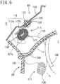
- FIG. 5 is a schematic cross-sectional view of this known head-protection airbag device in a folded state.
- the above-described conventional airbag device includes an airbag 111 in a folded state, the airbag 111 being attached to the upper part of the side wall inside the vehicle cabin so as to extend in the vehicle front-rear direction; an airbag cover 108 that covers a vehicle-cabin-interior side portion of the airbag 111; and an inflator (not shown) that supplies gas to the airbag 111 to inflate and deploy the airbag downward inside the vehicle cabin.
- the airbag 111 is stored in a space surrounded by the upper part of a pillar garnish 107, an inner panel 102 on the vehicle body side, and the airbag cover 108 in such a manner that it is wrapped in a wrapping member and is maintained in a folded shape.
- the airbag 111 includes an attachment portion 125 that has an attachment bracket 130 on the upper edge side thereof and is securely fixed to the inner panel 102 with an attachment bolt 131 inserted through this attachment bracket 130.
- the airbag 111 in a stored state as shown in the figure, includes a roll-folded portion 138 formed by rolling the airbag 111 from the lower edge and a supply path portion 115 continuous with the roll-folded portion 138.
- the supply path portion 115 is a portion into which inflation gas flows at the beginning of inflation of the airbag 111, the upper edge of the supply path portion 115 being disposed in the front-rear direction of the vehicle. As shown in the figure, the supply path portion 115 is provided with an inverted U-shaped portion 141 that is bent into an inverted U shape so as to cover the upper part of the roll-folded portion 138.
- the inverted U-shaped portion 141 of the supply path portion 115 is formed such that a portion 115b located on the upper side when inflation and deployment are completed is located on a vehicle-exterior side O and a portion 115c located on the lower side when inflation and deployment are completed is located on a vehicle-interior side I.
- the airbag cover 108 is disposed so as to cover a portion on the vehicle-interior side I of the folded and stored airbag 111 and, as shown by a dashed line in the figure, is pushed by the supply path portion 115, which is deployed at the beginning of inflation of the airbag 111, and is opened into the vehicle-interior side I to allow the airbag 111 to pass therethrough toward the vehicle-interior side I.
- the conventional airbag 111 is configured as described above, when the inflation gas from the inflator is supplied to the supply path portion 115 at the time of inflation and deployment, the inverted U-shaped portion 141, which is disposed so as to wrap the upper part of the roll-folded portion 138, is inflated and deployed first.
- the inverted U-shaped portion 141 is inflated and deployed, the roll-folded portion 138 is pushed downward in the figure due to the pressure and strikes an inclined upper end 107a of the pillar garnish 107.
- the roll-folded portion 138 enters the vehicle cabin through the cover 108, which has been pushed and opened by the inflating and deploying inverted U-shaped portion 141, and is deployed along the pillar garnish 107 while unfolding the roll fold rolled so as to be deployed toward the vehicle-exterior side O.
- this airbag device is configured such that the supply path portion 115, which is inflated at the initial stage of deployment, strongly pushes the roll-folded portion 138 downward at the beginning of inflation and deployment, causing it to strike the inclined upper end 107a of the pillar garnish 107, that is, such that the roll-folded portion 138 is caused to strike the inclined upper end 107a of the pillar garnish 107 before entering the vehicle-interior side I, there is a problem in that the speed at which it enters the vehicle cabin decreases correspondingly.
- US 2007/0075530 A1 discloses an air bag device according to the preamble of claim 1, including a roll part configured to be wound in a form of a roll when the air bag is in a folded state to be installed in a vehicle.
- the roll part includes a pushed part formed by pushing a part of an outer face of the air bag inward to the roll part in a certain pushing direction, such that the roll part has a decreased cross section by the pushing.
- the present invention has been made in view of the above-described problem of the conventional airbag device, and an object thereof is to enable an airbag to be quickly deployed without reducing the deployment speed of the airbag by omitting an action of strongly pushing the airbag downward, causing the airbag to once strongly strike a pillar trim (or pillar garnish) at the initial stage of deployment, as in the conventional configuration.
- the present invention is an airbag device including an airbag attached to an upper part of a side wall inside a vehicle cabin in the front-rear direction of a vehicle, and an inflator that inflates and deploys the folded airbag toward the lower side of the vehicle cabin.
- the airbag includes a roll-folded portion rolled from one end thereof opposite from an upper edge attached to the upper part, and an accordion-folded portion continuous with the roll-folded portion and folded in an accordion manner.
- the accordion-folded portion is folded so as to be located at a side of the roll-folded portion.
- the accordion-folded portion is formed by a folding line to have the same width as the width of the roll-folded portion folded into two, and is located at a side facing to the vehicle-exterior of the two-folded portion of the roll-folded portion.
- the airbag when the airbag is deployed, it is possible to cause the accordion-folded portion to directly push the roll-folded portion in a compact state, in which it is folded into two, from the storage portion toward the vehicle-cabin-interior side, in the vehicle width direction. That is, the airbag is not strongly pushed downward at the initial stage of deployment.
- the airbag because the airbag is not strongly urged against the lower portion of the airbag storage portion (e.g., an upper end portion of the pillar trim) at the initial stage of deployment, as in the conventional configuration, the deployment speed does not decrease, and quick deployment is possible.
- the attachment of the pillar trim it is possible to ease the strength requirement and shape requirement set based on an assumption that it comes into contact with the airbag and diverts the deployment direction of the airbag.
- An airbag device is of a type that inflates and deploys an airbag downward from the upper part (upper edge) of a side wall inside a vehicle cabin, along the side wall inside the vehicle cabin, and includes an inflatable airbag folded in a predetermined state, and an inflator that generates gas and supplies the gas to the airbag in an emergency of the vehicle or when an impact is detected.
- a side airbag device that inflates and deploys an airbag like a curtain from the upper part of the side wall inside the vehicle cabin and deploys the airbag over a predetermined area, on the vehicle-interior side, of the side wall inside the vehicle cabin, from a driver's seat and a passenger's seat to rear seats on the rear side of the vehicle to protect, mainly, the head of occupants in the front and rear seats.
- FIG. 1A is a front view of an airbag device 1 according to an embodiment of the present invention, showing the side wall of the vehicle and the airbag device 1 through an inner surface of the vehicle, while omitting the rear side of the vehicle.
- FIG. 1B is a front view showing the entirety of an airbag 10 of the airbag device 1 in FIG. 1 . In both figures, the airbag 10 is shown in a deployed state.
- the airbag device 1 includes the airbag 10 and the inflator 2. As will be described below, the airbag (herein, a curtain airbag) 10 is folded in an elongated shape in a stored state.
- the airbag device 1 is installed in a vehicle 90 and, when receiving an activation signal, activates the inflator 2 to generate gas. This gas is supplied to an inflatable section 30 of the airbag 10, thereby unfolding the airbag 10, as will be described below, to an inflated and deployed state like a curtain, as shown in FIG. 1A .
- the vehicle 90 includes, on a side wall 91 inside the vehicle cabin, a roof rail 92 located on the upper side, a front pillar (A pillar) 93 located on the front side, a center pillar (B pillar) 94 located in the middle in the front-rear direction, and a rear pillar (C pillar) (not shown) located on the rear side.
- the side wall 91 has a front door 95 on the front side and a rear door 96 on the rear side.
- a pillar trim 91A (see FIG. 4 ) and a headlining 92A are attached to the side wall 91, the pillar trim 91A constituting a surface member inside the vehicle 90 (interior member).
- the headlining 92A covers a roof (not shown) and the roof rail 92.
- the airbag 10 is disposed from the rear pillar to the front pillar 93, along the upper part (upper edge) of the side wall 91 inside the vehicle cabin.
- the airbag 10 is a rectangular bag in a developed state and is formed of, for example, base fabric pieces made of resin-coated fabric.
- the airbag 10 includes a front base fabric piece (front panel) 12 on the occupant side and a back base fabric piece (back panel) 13 on the side wall 91 side.
- the airbag 10 has a gas supply port 14, a beltlike connecting member 20, and a plurality of (in FIG. 1B , six) fixing fabric pieces 21 to 26.
- One end of the connecting member 20 is attached to the front end of the airbag 10, and the other end thereof is attached to the front pillar 93.
- a plurality of fixing fabric pieces 21 to 26 have a rectangular shape and are formed integrally at the upper edge of the airbag 10. Furthermore, the fixing fabric pieces 21 to 26 are arranged over the entire upper edge of the airbag 10.
- the connecting member 20 and the fixing fabric pieces 21 to 26 are fixed to predetermined positions of the front pillar 93 and the roof rail 92 with fixing means (not shown), such as bolts, whereby the airbag 10 is attached to the upper part of the vehicle body.
- the front base fabric piece 12 and the back base fabric piece 13 are formed in the same shape, are superposed on each other, and are joined along the outer-peripheral joining portion 15.
- the airbag 10 is delimited by the outer-peripheral joining portion 15, and an inflatable section 30 is formed between the base fabric pieces 12 and 13. More specifically, the outer-peripheral joining portion 15 determines the outer-peripheral shape of the inflatable section 30, and the base fabric pieces 12 and 13 are joined together at the outer-peripheral joining portion 15 in an air-tight manner, by being sewn together along the outer-peripheral joining portion 15 or by being sealed, at the seam, with an adhesive.
- the front inflatable section 31 is formed to have the largest length in the front-rear direction in the inflatable section 30 and is inflated at a side of the window portion in the front door 95 and the center pillar 94 to receive, mainly, the occupant in the front seat.
- the rear inflatable section 32 is formed to have a smaller length than the front inflatable section 31 in the front-rear direction, is disposed on the rear side of the airbag 10, and is inflated above the rear door to receive, mainly, the occupant in the rear seat.
- the connecting inflatable section 33 is provided between the front inflatable section 31 and the rear inflatable section 32 to connect the inflatable sections 31 and 32 at the upper edge of the airbag 10.
- a non-inflatable section 34 that extends upward from the lower edge of the airbag 10 is formed among the three inflatable sections 30 (31, 32, 33).
- the non-inflatable section 34 of the airbag 10 is provided outside the inflatable section 30 and, hence, is maintained in an uninflated state even when the airbag 10 is inflated.
- the gas supply port 14 is an opening (insertion port) through which the inflator 2 is inserted into the airbag 10, and it is formed at a substantially intermediate position of the airbag 10 in the front-rear direction.
- the base fabric pieces 12 and 13 project obliquely upward from the upper edge of the airbag 10, at the gas supply port 14, and the side edges thereof are joined together so as to be continuous with the outer-peripheral joining portion 15.
- the gas supply port 14 is formed integrally at the upper edge of the airbag 10.
- the airbag 10 has first to fourth inner joining portions 16 to 19 in the inflatable section 30 delimited by the outer-peripheral joining portion 15.
- the base fabric pieces 12 and 13 are joined together by sewing and bonding at the plurality of inner joining portions 16 to 19.
- the inner joining portions 16, 17, and 19 extend inward of the inflatable section 30 from the outer-peripheral joining portion 15 and each end thereof is joined in a circular shape (circular portions 16A, 17A, and 19A)at an end in the inflatable section 30.
- both ends of the inner joining portion 18 are joined in a circular shape (circular portions 18A) in the inflatable section 30.
- the circular portions 16A to 19A of the inner joining portions 16 to 19 are arranged at a predetermined distance from the outer-peripheral joining portion 15 at the lower edge of the airbag 10.
- the inner joining portions 16 to 19 serve as partitions for dividing the inflatable section 30 and reduce the amount by which the inflatable section 30 is inflated in the vehicle width direction to make the airbag 10 be inflated in a predetermined shape.
- the inflatable section 30 is divided into first to fifth air chambers 35 to 39 by the inner joining portions 16 to 19.
- the inflator 2 is a cylinder-type gas generator having a cylindrical shape and has a gas discharge portion at an end in the length direction.
- the inflator 2 and the airbag 10 are connected via a gas introduction portion (diffuser) 35C that is sewn in a tubular shape and is formed on the airbag 10, and are mounted to the roof rail 92 within the headlining 92A via an attachment bracket (not shown), which is connecting means, at a position above the center pillar 94.
- a gas introduction portion (diffuser) 35C that is sewn in a tubular shape and is formed on the airbag 10
- an attachment bracket (not shown), which is connecting means, at a position above the center pillar 94.
- the gas supply port 14 is fixed to the inflator 2 in an air-tight manner with a clamp or a band (not shown) that is fastened from the outside.
- the gas generated by the inflator 2 (inflation gas) flows from the gas supply port 14 into the first to fifth air chambers 35 to 39.
- the first air chamber 35 is completely inflated at a predetermined time after the other air chambers 36 and 37 have been completely inflated.
- the fourth and the fifth air chambers 38 and 39 are inflated according to the order in which the gas flows therein.
- FIGS. 2A to 2D are diagrams schematically showing the process of folding the above-described airbag 10.
- FIG. 2A shows the airbag 10 formed of the front base fabric piece 12 and the back base fabric piece 13, before being folded.
- the side to the left of the airbag 10 is the vehicle-exterior side
- the side to the right of the airbag 10 is the vehicle-interior side.
- FIG. 2A first, the uninflated airbag 10 is spread out such that the base fabric pieces 12 and 13 are laid flat on each other.
- the lower edge of the airbag 10 is folded several times in direction M1, with a constant width L1, toward the upper edge so as to be rolled on the vehicle-exterior side, thus making a predetermined number of roll-folds, rolled toward the vehicle-exterior side, until a state shown in FIG. 2B is reached.
- reference sign a in FIG. 2 indicates a starting point of an accordion-folded portion 10J of the airbag 10.
- a roll-folded portion (roll-folded portion) 10R of the airbag 10 in FIG. 2B is folded counterclockwise (in direction M2) at a midpoint, c, of the other surface thereof in the roll width (L1) direction and, then, is folded into two in a U shape (valley fold) at the midpoint c ( FIG. 2C ).
- FIG. 2D shows the thus-obtained folded airbag 10 including the accordion-folded portion 10J on the left side and the roll-folded portion 10R on the right side, which are side-by-side.
- reference sign d in FIG. 2D indicates a terminal point of the accordion-folded portion 10J as well as a starting point of the roll-folded portion 10R.
- the region between d and e is an initially inflated part of the roll-folded portion 10RS of the roll-folded portion 10R continuous with the accordion-folded portion 10J.
- reference sign f in the figure indicates a portion located at a substantially intermediate position, on the interior side, of the roll width L2 of the two-folded roll-folded portion 10R, the portion being the most vehicle-cabin-interior side of the roll-folded portion 10R.
- a tearable wrapping member (not shown) for preventing deformation of the folded shape is wound in a suitable way on a predetermined portion of the airbag 10 in the longitudinal direction, thus completing folding.
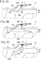
- FIG. 3A is a partial enlarged view of FIG. 1B , showing a portion in the vicinity of the gas introduction portion (diffuser) 35C of the airbag 10, according to the embodiment of the present invention.
- the gas supply port 14 of the airbag 10 through which the gas from the inflator is supplied is provided at the upper edge of the airbag 10, at a portion at the opposite end of the accordion-folded portion from the roll-folded portion, so that the airbag is inflated and deployed initially from the according portion with the gas from the inflator, when the inflator is activated.
- an upper edge 30H of the inflatable section 30 of the airbag 10 is located closer to the upper edge of the airbag 10 than the folding line (bent portion) b in FIG. 2 , more desirably, at a position substantially equal to the position of the starting point, a, of the accordion-folded portion 10J.
- the starting point a of the accordion-folded portion 10J be located at the upper edge 30H of the inflatable section 30 of the airbag 10.
- the gas introduction portion 35C when used to introduce the gas from the inflator 2 into the inflatable section 30 of the airbag 10, it is configured such that an upper end 35DH of gas discharge ports 35D of the gas introduction portion 35C is located closer to the upper edge of the airbag 10 than the bent portion b in FIG. 2 , more desirably, substantially at the position of the starting point, a ,of the accordion-folded portion 10J, and such that a lower end 35DL of the gas discharge ports 35D is located at the position of the initially inflated part of the roll-folded portion 10RS (the position between d and e in FIG. 2 ), more desirably, at a position between c and e of the initially inflated part of the roll-folded portion 10RS in FIG. 2 .
- an area from the accordion-folded portion 10J to a portion on the lower edge side beyond the initially inflated part of the roll-folded portion 10RS of the roll-folded portion 10R (the portion from e to f in FIG. 2D ), especially in the vicinity of the gas discharge ports 35D, can be more quickly inflated.
- the airbag it is possible to cause the airbag to be more quickly deployed toward the vehicle-interior side, beyond the pillar trim 91A ( FIG. 4 ), and downward along the pillar trim 91A (side wall 91) while unfolding the roll fold.
- FIGS. 3B and 3C show embodiments in which the shape of the gas introduction portion 35C is different from that in FIG. 3A .
- the gas introduction portion 35C in FIG. 3B has a substantially inverted T shape in front view, in which the gas discharge ports 35D are provided at the left and right side surfaces thereof, similarly to FIG. 3A .
- the gas hitting the lower end portion of the gas introduction portion 35C is split substantially horizontally toward the side surfaces thereof, i.e., to the left and right in the figure.
- the gas introduction portion 35C in FIG. 3C has a substantially I shape in front view, similarly to that shown in FIG. 3A , but it has the gas discharge ports 35D in the bottom and one side surface thereof (in the example shown, in the right side surface). Thus, the gas introduced therein is split toward the lower end and toward the right side surface.
- each gas introduction portion 35C the upper end 35DH and the lower end 35DL of the gas discharge ports 35D are as illustrated, and the relationship with respect to the portions a to f in FIG. 2D is the same as the description on FIG. 3A .
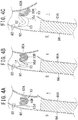
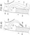
- FIGS. 4A to 4H show, in sequence, the airbag 10 according to this embodiment being deployed.
- FIG. 4A is a diagram schematically showing the airbag 10 attached to the vehicle, the airbag being folded in a state shown in FIG. 2D , i.e., in a shape which the accordion-folded portion 10J and the roll-folded portion 10R are side-by-side in the vehicle width direction.
- FIG. 4A shows, in outline, cross sections taken at the B pillar of the vehicle.
- the airbag 10, in a folded state, is fixed to the roof rail 92 ( FIG. 1A ) with fixing means 82 including, for example, bolts and nuts at the upper end thereof (fixing fabric pieces). Furthermore, the airbag 10 is stored in a storage portion surrounded by an upper end portion of the pillar trim 91A and the headlining 92A, which is made of, for example, plastic and is attached to the roof rail 92 in such a manner that a portion covering the vehicle-interior side (i.e., the airbag cover) can be opened toward the vehicle-interior side I (vehicle-cabin-interior side).
- fixing means 82 including, for example, bolts and nuts at the upper end thereof (fixing fabric pieces).
- the airbag 10 is stored in a storage portion surrounded by an upper end portion of the pillar trim 91A and the headlining 92A, which is made of, for example, plastic and is attached to the roof rail 92 in such a manner that a portion covering the vehicle-interior
- the airbag device 1 installed in the vehicle activates the inflator 2 ( FIG. 1 ), causing it to generate inflation gas, and supplies the inflation gas to the airbag 10 (first to fifth air chambers 35 to 39).
- the inflation gas is introduced into the first to fifth air chambers 35 to 39, inflating the air chambers 35 to 39, whereby the airbag 10 is inflated and deployed like a curtain toward the inside of the vehicle cabin, located on the lower side of the vehicle, from the upper part of the vehicle side wall where the fixing fabric pieces 21 to 26 are provided.
- the inflator 2 when the inflator 2 is activated, and the inflation gas is generated due to a vehicle collision or the like, the generated inflation gas is introduced into the accordion-folded portion 10J of the airbag 10 via the gas supply port 14 of the airbag 10. As a result, the airbag 10 starts to be inflated with the inflation gas from the inflator 2.
- the accordion-folded portion 10J When the wrapping member wound around the folded airbag 10 is detached, the accordion-folded portion 10J is first deployed while being inflated, pushing out the roll-folded portion 10R located to the vehicle-interior side I thereof toward the headlining 92A.
- the roll-folded portion 10R pushed out toward the headlining 92A strikes the headlining 92A.
- the airbag 10 (roll-folded portion 10R) receives a reaction force from the headlining 92A and is prevented from being deployed from a two-fold state. As a result, the airbag 10 pushes and opens the headlining 92A, serving as the airbag cover, and bursts out in the cabin ( FIG. 3B ), while maintaining a compact shape.
- the initially inflated part of the roll-folded portion 10RS (the portion from d to e in FIG.
- the roll-folded portion 10R having returned to substantially the original roll-fold width L1 is pushed by the initially inflated part of the roll-folded portion 10RS, which is being inflated, and the lower end portion thereof (the portion between e and f in FIG. 2D ), which starts to be inflated, and passes the pillar trim 91A ( FIGS. 4D, 4E, 4F ), while being rotated in the direction of the vehicle-exterior side O, i.e., herein, counterclockwise, and returning to the original roll-fold width L1.
- the roll-folded portion 10R When the roll-folded portion 10R has passed the pillar trim 91A, the roll-folded portion 10R, while being inflated sequentially from a portion following the initially inflated part of the roll-folded portion 10RS, is pushed by the inflating portion, is rotated in the direction opposite to the winding direction (in the direction of the vehicle-exterior side O), and is deployed downward while moving in the direction of the vehicle-exterior side O ( FIG. 4G ).
- the roll-folded portion 10R after passing the upper end portion of the pillar trim 91A, is deployed along the pillar trim 91A (side wall 91), and after that, the roll-folded portion 10R is repeatedly rotated in the direction of the vehicle-exterior side O while being inflated along the pillar trim 91A (side wall 91) and is deployed downward while unfolding the roll fold ( FIG. 4H ).
- the length of the accordion-folded portion 10J of the airbag 10 is set such that the roll-folded portion 10R bursts out from the pillar trim 91A toward the vehicle-interior side I while the accordion-folded portion 10J is being inflated and deployed.
- the airbag 10 having burst out into the vehicle cabin is deployed toward the vehicle-exterior side O and downward, between the side of the occupant and the window, that is, between the occupant's head and the vehicle window.
- it can reliably protect the occupant with the inflated first to fifth air chambers 35 to 39.
- the airbag 10 deploys first to the side, toward the vehicle-interior side I.
- the two-folded roll-folded portion 10R of the airbag 10 pushes and opens the headlining 92A, serving as the airbag cover, while maintaining a compact, substantially two-folded state, and passes the upper end of the pillar trim 91A, while unfolding the two fold.
- the roll-folded portion 10R is not strongly pushed toward the pillar trim 91A in the process in which the accordion-folded portion 10J is deployed, as in the conventional configuration.
- the airbag 10 (roll-folded portion 10R) is strongly pressed against the pillar trim 91A, decreasing the deployment speed thereof.
- the roll-folded portion 10R is smoothly deployed, starting from the initially inflated part of the roll-folded portion 10RS.
- the deployment speed can be increased.
- the airbag 10 is deployed toward the vehicle-exterior side O, while unfolding the roll fold, after the accordion fold is unfolded, it can be easily inflated and deployed between the occupant and the window pane and reliably protect the occupant.
- the roll fold is folded into two at the time of assembly, the number of roll folds can be reduced compared with the case where the roll fold is not folded into two.
- advantages such as an increase in production efficiency and a reduction in cross-sectional area of the folded airbag.
Description
- The present invention relates to an airbag device that is installed in a vehicle, such as a car, to protect an occupant, and, for example, it relates to an airbag device that deploys, in a vehicle cabin, an airbag like a curtain in the front-rear direction of the vehicle.
- A known airbag device in the related art is configured to store a folded airbag in the upper part of a side wall inside a vehicle cabin, a vehicle-interior side portion thereof being covered with an airbag cover, and is configured to quickly inflate and deploy an airbag along the side wall inside the vehicle cabin, while reducing the amount by which the airbag projects toward the vehicle-interior side when inflated and deployed by folding the upper part and lower part of the airbag in different ways (seeJP 2004-58848 A).
-
FIG. 5 is a schematic cross-sectional view of this known head-protection airbag device in a folded state. - The above-described conventional airbag device includes an
airbag 111 in a folded state, theairbag 111 being attached to the upper part of the side wall inside the vehicle cabin so as to extend in the vehicle front-rear direction; anairbag cover 108 that covers a vehicle-cabin-interior side portion of theairbag 111; and an inflator (not shown) that supplies gas to theairbag 111 to inflate and deploy the airbag downward inside the vehicle cabin. - The
airbag 111 is stored in a space surrounded by the upper part of apillar garnish 107, aninner panel 102 on the vehicle body side, and theairbag cover 108 in such a manner that it is wrapped in a wrapping member and is maintained in a folded shape. Theairbag 111 includes anattachment portion 125 that has anattachment bracket 130 on the upper edge side thereof and is securely fixed to theinner panel 102 with anattachment bolt 131 inserted through thisattachment bracket 130. - The
airbag 111, in a stored state as shown in the figure, includes a roll-foldedportion 138 formed by rolling theairbag 111 from the lower edge and asupply path portion 115 continuous with the roll-foldedportion 138. - The
supply path portion 115 is a portion into which inflation gas flows at the beginning of inflation of theairbag 111, the upper edge of thesupply path portion 115 being disposed in the front-rear direction of the vehicle. As shown in the figure, thesupply path portion 115 is provided with an invertedU-shaped portion 141 that is bent into an inverted U shape so as to cover the upper part of the roll-foldedportion 138. - The inverted U-shaped
portion 141 of thesupply path portion 115 is formed such that aportion 115b located on the upper side when inflation and deployment are completed is located on a vehicle-exterior side O and aportion 115c located on the lower side when inflation and deployment are completed is located on a vehicle-interior side I. - The
airbag cover 108 is disposed so as to cover a portion on the vehicle-interior side I of the folded and storedairbag 111 and, as shown by a dashed line in the figure, is pushed by thesupply path portion 115, which is deployed at the beginning of inflation of theairbag 111, and is opened into the vehicle-interior side I to allow theairbag 111 to pass therethrough toward the vehicle-interior side I. - Because the
conventional airbag 111 is configured as described above, when the inflation gas from the inflator is supplied to thesupply path portion 115 at the time of inflation and deployment, the inverted U-shapedportion 141, which is disposed so as to wrap the upper part of the roll-foldedportion 138, is inflated and deployed first. When the invertedU-shaped portion 141 is inflated and deployed, the roll-foldedportion 138 is pushed downward in the figure due to the pressure and strikes an inclinedupper end 107a of thepillar garnish 107. Subsequently, the roll-foldedportion 138 enters the vehicle cabin through thecover 108, which has been pushed and opened by the inflating and deploying inverted U-shapedportion 141, and is deployed along thepillar garnish 107 while unfolding the roll fold rolled so as to be deployed toward the vehicle-exterior side O. - However, as has been described above, because this airbag device is configured such that the
supply path portion 115, which is inflated at the initial stage of deployment, strongly pushes the roll-foldedportion 138 downward at the beginning of inflation and deployment, causing it to strike the inclinedupper end 107a of thepillar garnish 107, that is, such that the roll-foldedportion 138 is caused to strike the inclinedupper end 107a of thepillar garnish 107 before entering the vehicle-interior side I, there is a problem in that the speed at which it enters the vehicle cabin decreases correspondingly. -
US 2007/0075530 A1 discloses an air bag device according to the preamble ofclaim 1, including a roll part configured to be wound in a form of a roll when the air bag is in a folded state to be installed in a vehicle. The roll part includes a pushed part formed by pushing a part of an outer face of the air bag inward to the roll part in a certain pushing direction, such that the roll part has a decreased cross section by the pushing. - The present invention has been made in view of the above-described problem of the conventional airbag device, and an object thereof is to enable an airbag to be quickly deployed without reducing the deployment speed of the airbag by omitting an action of strongly pushing the airbag downward, causing the airbag to once strongly strike a pillar trim (or pillar garnish) at the initial stage of deployment, as in the conventional configuration. Solution to Problem
- The present invention is an airbag device including an airbag attached to an upper part of a side wall inside a vehicle cabin in the front-rear direction of a vehicle, and an inflator that inflates and deploys the folded airbag toward the lower side of the vehicle cabin. The airbag includes a roll-folded portion rolled from one end thereof opposite from an upper edge attached to the upper part, and an accordion-folded portion continuous with the roll-folded portion and folded in an accordion manner. The accordion-folded portion is folded so as to be located at a side of the roll-folded portion. The accordion-folded portion is formed by a folding line to have the same width as the width of the roll-folded portion folded into two, and is located at a side facing to the vehicle-exterior of the two-folded portion of the roll-folded portion.
- According to the present invention, when the airbag is deployed, it is possible to cause the accordion-folded portion to directly push the roll-folded portion in a compact state, in which it is folded into two, from the storage portion toward the vehicle-cabin-interior side, in the vehicle width direction. That is, the airbag is not strongly pushed downward at the initial stage of deployment. Thus, because the airbag is not strongly urged against the lower portion of the airbag storage portion (e.g., an upper end portion of the pillar trim) at the initial stage of deployment, as in the conventional configuration, the deployment speed does not decrease, and quick deployment is possible. Furthermore, in the attachment of the pillar trim, it is possible to ease the strength requirement and shape requirement set based on an assumption that it comes into contact with the airbag and diverts the deployment direction of the airbag.
-
- [
FIG. 1] FIG. 1A is a front view of an airbag device according to an embodiment of the present invention, showing a side wall of a vehicle and the airbag device through an inner surface of the vehicle, while omitting the rear side of the vehicle.FIG. 1B is a front view showing the entirety of an airbag of the airbag device inFIG. 1 . In both figures, the airbag is shown in a deployed state. - [
FIG. 2] FIG. 2 includes diagrams schematically showing a process of folding the airbag of the airbag device according to this embodiment. - [
FIG. 3] FIG. 3A is a partially enlarged view ofFIG. 1B , showing a portion in the vicinity of a gas introduction portion according to the embodiment of the present invention. -
FIGS. 3B and 3C are diagrams similar toFIG. 3A , each showing a gas introduction portion according to another embodiment. - [
FIGS. 4ABC] FIGS. 4A, 4B, and 4C are diagrams schematically showing the airbag, in which an accordion-folded portion and a roll-folded portion are side-by-side, attached to the vehicle. - [
FIGS. 4DEF] FIGS. 4D, 4E, and 4F are diagrams schematically showing the airbag, in which the accordion-folded portion and the roll-folded portion are side-by-side, attached to the vehicle. - [
FIGS. 4GH] FIGS. 4G and 4H are diagrams schematically showing the airbag, in which the accordion-folded portion and the roll-folded portion are side-by-side, attached to the vehicle. - [
FIG. 5] FIG. 5 is a schematic diagram for explaining a process of folding a conventional airbag. - An embodiment of an airbag device according to the present invention will be described with reference to the drawings.
- An airbag device according to this embodiment is of a type that inflates and deploys an airbag downward from the upper part (upper edge) of a side wall inside a vehicle cabin, along the side wall inside the vehicle cabin, and includes an inflatable airbag folded in a predetermined state, and an inflator that generates gas and supplies the gas to the airbag in an emergency of the vehicle or when an impact is detected.
- The following description will be given by taking, as an example, a side airbag device that inflates and deploys an airbag like a curtain from the upper part of the side wall inside the vehicle cabin and deploys the airbag over a predetermined area, on the vehicle-interior side, of the side wall inside the vehicle cabin, from a driver's seat and a passenger's seat to rear seats on the rear side of the vehicle to protect, mainly, the head of occupants in the front and rear seats.
-
FIG. 1A is a front view of anairbag device 1 according to an embodiment of the present invention, showing the side wall of the vehicle and theairbag device 1 through an inner surface of the vehicle, while omitting the rear side of the vehicle.FIG. 1B is a front view showing the entirety of anairbag 10 of theairbag device 1 inFIG. 1 . In both figures, theairbag 10 is shown in a deployed state. - The
airbag device 1 includes theairbag 10 and theinflator 2. As will be described below, the airbag (herein, a curtain airbag) 10 is folded in an elongated shape in a stored state. - The
airbag device 1 is installed in avehicle 90 and, when receiving an activation signal, activates theinflator 2 to generate gas. This gas is supplied to aninflatable section 30 of theairbag 10, thereby unfolding theairbag 10, as will be described below, to an inflated and deployed state like a curtain, as shown inFIG. 1A . - As shown in the figure, the
vehicle 90 includes, on aside wall 91 inside the vehicle cabin, aroof rail 92 located on the upper side, a front pillar (A pillar) 93 located on the front side, a center pillar (B pillar) 94 located in the middle in the front-rear direction, and a rear pillar (C pillar) (not shown) located on the rear side. Theside wall 91 has afront door 95 on the front side and arear door 96 on the rear side. - A pillar trim 91A (see
FIG. 4 ) and aheadlining 92A are attached to theside wall 91, the pillar trim 91A constituting a surface member inside the vehicle 90 (interior member). The headlining 92A covers a roof (not shown) and theroof rail 92. - The
airbag 10 is disposed from the rear pillar to thefront pillar 93, along the upper part (upper edge) of theside wall 91 inside the vehicle cabin. As shown inFIG. 1B , theairbag 10 is a rectangular bag in a developed state and is formed of, for example, base fabric pieces made of resin-coated fabric. Theairbag 10 includes a front base fabric piece (front panel) 12 on the occupant side and a back base fabric piece (back panel) 13 on theside wall 91 side. Furthermore, theairbag 10 has agas supply port 14, abeltlike connecting member 20, and a plurality of (inFIG. 1B , six) fixingfabric pieces 21 to 26. - One end of the connecting
member 20 is attached to the front end of theairbag 10, and the other end thereof is attached to thefront pillar 93. A plurality of fixingfabric pieces 21 to 26 have a rectangular shape and are formed integrally at the upper edge of theairbag 10. Furthermore, the fixingfabric pieces 21 to 26 are arranged over the entire upper edge of theairbag 10. The connectingmember 20 and the fixingfabric pieces 21 to 26 are fixed to predetermined positions of thefront pillar 93 and theroof rail 92 with fixing means (not shown), such as bolts, whereby theairbag 10 is attached to the upper part of the vehicle body. - Like the typical airbag, the front
base fabric piece 12 and the backbase fabric piece 13 are formed in the same shape, are superposed on each other, and are joined along the outer-peripheral joiningportion 15. Theairbag 10 is delimited by the outer-peripheral joiningportion 15, and aninflatable section 30 is formed between thebase fabric pieces portion 15 determines the outer-peripheral shape of theinflatable section 30, and thebase fabric pieces portion 15 in an air-tight manner, by being sewn together along the outer-peripheral joiningportion 15 or by being sealed, at the seam, with an adhesive. - A front
inflatable section 31, a rearinflatable section 32, and a connectinginflatable section 33, which are delimited by the outer-peripheral joiningportion 15, are formed in theairbag 10. The frontinflatable section 31 is formed to have the largest length in the front-rear direction in theinflatable section 30 and is inflated at a side of the window portion in thefront door 95 and thecenter pillar 94 to receive, mainly, the occupant in the front seat. - The rear
inflatable section 32 is formed to have a smaller length than the frontinflatable section 31 in the front-rear direction, is disposed on the rear side of theairbag 10, and is inflated above the rear door to receive, mainly, the occupant in the rear seat. The connectinginflatable section 33 is provided between the frontinflatable section 31 and the rearinflatable section 32 to connect theinflatable sections airbag 10. - A
non-inflatable section 34 that extends upward from the lower edge of theairbag 10 is formed among the three inflatable sections 30 (31, 32, 33). Thenon-inflatable section 34 of theairbag 10 is provided outside theinflatable section 30 and, hence, is maintained in an uninflated state even when theairbag 10 is inflated. - The
gas supply port 14 is an opening (insertion port) through which theinflator 2 is inserted into theairbag 10, and it is formed at a substantially intermediate position of theairbag 10 in the front-rear direction. Thebase fabric pieces airbag 10, at thegas supply port 14, and the side edges thereof are joined together so as to be continuous with the outer-peripheral joiningportion 15. Thus, thegas supply port 14 is formed integrally at the upper edge of theairbag 10. - The
airbag 10 has first to fourth inner joiningportions 16 to 19 in theinflatable section 30 delimited by the outer-peripheral joiningportion 15. Thebase fabric pieces portions 16 to 19. The inner joiningportions inflatable section 30 from the outer-peripheral joiningportion 15 and each end thereof is joined in a circular shape (circular portions inflatable section 30. Furthermore, both ends of the inner joiningportion 18 are joined in a circular shape (circular portions 18A) in theinflatable section 30. - The
circular portions 16A to 19A of the inner joiningportions 16 to 19 are arranged at a predetermined distance from the outer-peripheral joiningportion 15 at the lower edge of theairbag 10. The inner joiningportions 16 to 19 serve as partitions for dividing theinflatable section 30 and reduce the amount by which theinflatable section 30 is inflated in the vehicle width direction to make theairbag 10 be inflated in a predetermined shape. - In this embodiment, the
inflatable section 30 is divided into first tofifth air chambers 35 to 39 by the inner joiningportions 16 to 19. - The
inflator 2 is a cylinder-type gas generator having a cylindrical shape and has a gas discharge portion at an end in the length direction. - The
inflator 2 and theairbag 10 are connected via a gas introduction portion (diffuser) 35C that is sewn in a tubular shape and is formed on theairbag 10, and are mounted to theroof rail 92 within the headlining 92A via an attachment bracket (not shown), which is connecting means, at a position above thecenter pillar 94. - The
gas supply port 14 is fixed to theinflator 2 in an air-tight manner with a clamp or a band (not shown) that is fastened from the outside. The gas generated by the inflator 2 (inflation gas) flows from thegas supply port 14 into the first tofifth air chambers 35 to 39. Of these air chambers, thefirst air chamber 35 is completely inflated at a predetermined time after theother air chambers fifth air chambers -
FIGS. 2A to 2D are diagrams schematically showing the process of folding the above-describedairbag 10. -
FIG. 2A shows theairbag 10 formed of the frontbase fabric piece 12 and the backbase fabric piece 13, before being folded. - In the figure, the side to the left of the
airbag 10 is the vehicle-exterior side, and the side to the right of theairbag 10 is the vehicle-interior side. As shown inFIG. 2A , first, theuninflated airbag 10 is spread out such that thebase fabric pieces airbag 10 is folded several times in direction M1, with a constant width L1, toward the upper edge so as to be rolled on the vehicle-exterior side, thus making a predetermined number of roll-folds, rolled toward the vehicle-exterior side, until a state shown inFIG. 2B is reached. Note that reference sign a inFIG. 2 indicates a starting point of an accordion-foldedportion 10J of theairbag 10. - Next, a roll-folded portion (roll-folded portion) 10R of the
airbag 10 inFIG. 2B is folded counterclockwise (in direction M2) at a midpoint, c, of the other surface thereof in the roll width (L1) direction and, then, is folded into two in a U shape (valley fold) at the midpoint c (FIG. 2C ). Thereafter, an airbag portion linearly extending from the intermediate position of the two-folded roll-foldedportion 10R is bent in direction M3 toward the lower edge of theairbag 10, along the roll-foldedportion 10R on the vehicle-exterior side, and is folded back in direction M4 toward the upper edge of theairbag 10, at a portion (folding line b) having the same width (vertical width) as the roll width L2 of the two-folded roll-foldedportion 10R (i.e., accordion fold) (FIG. 2D). FIG. 2D shows the thus-obtained foldedairbag 10 including the accordion-foldedportion 10J on the left side and the roll-foldedportion 10R on the right side, which are side-by-side. - Herein, reference sign d in
FIG. 2D indicates a terminal point of the accordion-foldedportion 10J as well as a starting point of the roll-foldedportion 10R. The region between d and e (the region between top portions of the two-folded roll-folded portion) is an initially inflated part of the roll-folded portion 10RS of the roll-foldedportion 10R continuous with the accordion-foldedportion 10J. - Furthermore, reference sign f in the figure indicates a portion located at a substantially intermediate position, on the interior side, of the roll width L2 of the two-folded roll-folded
portion 10R, the portion being the most vehicle-cabin-interior side of the roll-foldedportion 10R. - After folded in the manner described above, similarly to the conventional configuration, a tearable wrapping member (not shown) for preventing deformation of the folded shape is wound in a suitable way on a predetermined portion of the
airbag 10 in the longitudinal direction, thus completing folding. - Next, referring to
FIG. 3 , the relationship between the portions a to f, which are shown inFIG. 2 in association with the accordion-foldedportion 10J and the roll-foldedportion 10R of the airbag, and theairbag 10 in a deployed state will be described. -
FIG. 3A is a partial enlarged view ofFIG. 1B , showing a portion in the vicinity of the gas introduction portion (diffuser) 35C of theairbag 10, according to the embodiment of the present invention. - First, in the figure, the
gas supply port 14 of theairbag 10 through which the gas from the inflator is supplied is provided at the upper edge of theairbag 10, at a portion at the opposite end of the accordion-folded portion from the roll-folded portion, so that the airbag is inflated and deployed initially from the according portion with the gas from the inflator, when the inflator is activated. Furthermore, anupper edge 30H of theinflatable section 30 of theairbag 10 is located closer to the upper edge of theairbag 10 than the folding line (bent portion) b inFIG. 2 , more desirably, at a position substantially equal to the position of the starting point, a, of the accordion-foldedportion 10J. In other words, it is desirable that the starting point a of the accordion-foldedportion 10J be located at theupper edge 30H of theinflatable section 30 of theairbag 10. - Furthermore, as in this example, when the
gas introduction portion 35C is used to introduce the gas from theinflator 2 into theinflatable section 30 of theairbag 10, it is configured such that an upper end 35DH ofgas discharge ports 35D of thegas introduction portion 35C is located closer to the upper edge of theairbag 10 than the bent portion b inFIG. 2 , more desirably, substantially at the position of the starting point, a ,of the accordion-foldedportion 10J, and such that a lower end 35DL of thegas discharge ports 35D is located at the position of the initially inflated part of the roll-folded portion 10RS (the position between d and e inFIG. 2 ), more desirably, at a position between c and e of the initially inflated part of the roll-folded portion 10RS inFIG. 2 . - By determining the positions of the starting point and terminal point of the accordion fold and roll fold and the above-described portions in association with the
upper edge 30H of the airbag, or the upper end 35DH of thegas discharge ports 35D, and the lower end 35DL of thegas discharge ports 35D in this manner, when theairbag 10 starts to be inflated, the inflation reliably starts from the accordion-foldedportion 10J. Furthermore, with the gas blown from thegas discharge ports 35D, an area from the accordion-foldedportion 10J to the initially inflated part of the roll-folded portion 10RS, especially in the vicinity of thegas discharge ports 35D, can be more quickly inflated. - Furthermore, by disposing the lower end 35DL of the
gas discharge ports 35D of thegas introduction portion 35C at the position of f inFIG. 2 , beyond the position of e inFIG. 2 , by, for example, extending the length of thegas introduction portion 35C, an area from the accordion-foldedportion 10J to a portion on the lower edge side beyond the initially inflated part of the roll-folded portion 10RS of the roll-foldedportion 10R (the portion from e to f inFIG. 2D ), especially in the vicinity of thegas discharge ports 35D, can be more quickly inflated. - Thus, it is possible to cause the airbag to be more quickly deployed toward the vehicle-interior side, beyond the pillar trim 91A (
FIG. 4 ), and downward along the pillar trim 91A (side wall 91) while unfolding the roll fold. -
FIGS. 3B and 3C show embodiments in which the shape of thegas introduction portion 35C is different from that inFIG. 3A . - More specifically, the
gas introduction portion 35C inFIG. 3B has a substantially inverted T shape in front view, in which thegas discharge ports 35D are provided at the left and right side surfaces thereof, similarly toFIG. 3A . Thus, the gas hitting the lower end portion of thegas introduction portion 35C is split substantially horizontally toward the side surfaces thereof, i.e., to the left and right in the figure. - The
gas introduction portion 35C inFIG. 3C has a substantially I shape in front view, similarly to that shown inFIG. 3A , but it has thegas discharge ports 35D in the bottom and one side surface thereof (in the example shown, in the right side surface). Thus, the gas introduced therein is split toward the lower end and toward the right side surface. - In each
gas introduction portion 35C, the upper end 35DH and the lower end 35DL of thegas discharge ports 35D are as illustrated, and the relationship with respect to the portions a to f inFIG. 2D is the same as the description onFIG. 3A . - Next, deployment of the above-described
airbag 10 will be described. -
FIGS. 4A to 4H show, in sequence, theairbag 10 according to this embodiment being deployed. -
FIG. 4A is a diagram schematically showing theairbag 10 attached to the vehicle, the airbag being folded in a state shown inFIG. 2D , i.e., in a shape which the accordion-foldedportion 10J and the roll-foldedportion 10R are side-by-side in the vehicle width direction.FIG. 4A shows, in outline, cross sections taken at the B pillar of the vehicle. - The
airbag 10, in a folded state, is fixed to the roof rail 92 (FIG. 1A ) with fixing means 82 including, for example, bolts and nuts at the upper end thereof (fixing fabric pieces). Furthermore, theairbag 10 is stored in a storage portion surrounded by an upper end portion of the pillar trim 91A and the headlining 92A, which is made of, for example, plastic and is attached to theroof rail 92 in such a manner that a portion covering the vehicle-interior side (i.e., the airbag cover) can be opened toward the vehicle-interior side I (vehicle-cabin-interior side). - When a vehicle collision occurs, the
airbag device 1 installed in the vehicle activates the inflator 2 (FIG. 1 ), causing it to generate inflation gas, and supplies the inflation gas to the airbag 10 (first tofifth air chambers 35 to 39). By doing so, while the folded portions are unfolded in sequence from the accordion-foldedportion 10J to the roll-foldedportion 10R, i.e., sequentially, the inflation gas is introduced into the first tofifth air chambers 35 to 39, inflating theair chambers 35 to 39, whereby theairbag 10 is inflated and deployed like a curtain toward the inside of the vehicle cabin, located on the lower side of the vehicle, from the upper part of the vehicle side wall where the fixingfabric pieces 21 to 26 are provided. - More specifically, when the
inflator 2 is activated, and the inflation gas is generated due to a vehicle collision or the like, the generated inflation gas is introduced into the accordion-foldedportion 10J of theairbag 10 via thegas supply port 14 of theairbag 10. As a result, theairbag 10 starts to be inflated with the inflation gas from theinflator 2. When the wrapping member wound around the foldedairbag 10 is detached, the accordion-foldedportion 10J is first deployed while being inflated, pushing out the roll-foldedportion 10R located to the vehicle-interior side I thereof toward theheadlining 92A. The roll-foldedportion 10R pushed out toward the headlining 92A strikes theheadlining 92A. When the roll-foldedportion 10R strikes the headlining 92A, the airbag 10 (roll-foldedportion 10R) receives a reaction force from theheadlining 92A and is prevented from being deployed from a two-fold state. As a result, theairbag 10 pushes and opens the headlining 92A, serving as the airbag cover, and bursts out in the cabin (FIG. 3B ), while maintaining a compact shape. At the same time, because the initially inflated part of the roll-folded portion 10RS (the portion from d to e inFIG. 2D ) starts to be inflated, the roll-foldedportion 10R of the freedairbag 10, folded into two in a U shape, is pushed and opened at the initially inflated part of the roll-folded portion 10RS and is returned to a substantially original roll-fold width L1 (seeFIG. 2 ) (FIGS. 4C and4D ). Note that, at this time, a force that strongly pushes the roll-folded portion downward is not generated, as in the case of the conventional airbag having an inverted U-shaped folded portion. - The roll-folded
portion 10R having returned to substantially the original roll-fold width L1 is pushed by the initially inflated part of the roll-folded portion 10RS, which is being inflated, and the lower end portion thereof (the portion between e and f inFIG. 2D ), which starts to be inflated, and passes the pillar trim 91A (FIGS. 4D, 4E, 4F ), while being rotated in the direction of the vehicle-exterior side O, i.e., herein, counterclockwise, and returning to the original roll-fold width L1. When the roll-foldedportion 10R has passed the pillar trim 91A, the roll-foldedportion 10R, while being inflated sequentially from a portion following the initially inflated part of the roll-folded portion 10RS, is pushed by the inflating portion, is rotated in the direction opposite to the winding direction (in the direction of the vehicle-exterior side O), and is deployed downward while moving in the direction of the vehicle-exterior side O (FIG. 4G ). That is, the roll-foldedportion 10R, after passing the upper end portion of the pillar trim 91A, is deployed along the pillar trim 91A (side wall 91), and after that, the roll-foldedportion 10R is repeatedly rotated in the direction of the vehicle-exterior side O while being inflated along the pillar trim 91A (side wall 91) and is deployed downward while unfolding the roll fold (FIG. 4H ). - Note that the length of the accordion-folded
portion 10J of theairbag 10 is set such that the roll-foldedportion 10R bursts out from the pillar trim 91A toward the vehicle-interior side I while the accordion-foldedportion 10J is being inflated and deployed. - As has been described above, when the
airbag 10 is inflated and deployed, only the accordion-foldedportion 10J is deployed in the storage portion (above the pillar trim 91A), and the roll-foldedportion 10R is pushed out to the side while being maintained in a compact, substantially two-fold state in the top-bottom direction. - The
airbag 10 having burst out into the vehicle cabin is deployed toward the vehicle-exterior side O and downward, between the side of the occupant and the window, that is, between the occupant's head and the vehicle window. Thus, it can reliably protect the occupant with the inflated first tofifth air chambers 35 to 39. - According to this embodiment, at the initial stage of deployment, the
airbag 10 deploys first to the side, toward the vehicle-interior side I. At this time, the two-folded roll-foldedportion 10R of theairbag 10 pushes and opens the headlining 92A, serving as the airbag cover, while maintaining a compact, substantially two-folded state, and passes the upper end of the pillar trim 91A, while unfolding the two fold. Thus, the roll-foldedportion 10R is not strongly pushed toward the pillar trim 91A in the process in which the accordion-foldedportion 10J is deployed, as in the conventional configuration. - Therefore, in the process of deploying the
airbag 10, at the initial stage of deployment, there is no possibility that the airbag 10 (roll-foldedportion 10R) is strongly pressed against the pillar trim 91A, decreasing the deployment speed thereof. In addition, once the two-fold is opened, the roll-foldedportion 10R is smoothly deployed, starting from the initially inflated part of the roll-folded portion 10RS. Thus, the deployment speed can be increased. - Furthermore, because the
airbag 10 is deployed toward the vehicle-exterior side O, while unfolding the roll fold, after the accordion fold is unfolded, it can be easily inflated and deployed between the occupant and the window pane and reliably protect the occupant. - Moreover, because the roll fold is folded into two at the time of assembly, the number of roll folds can be reduced compared with the case where the roll fold is not folded into two. Thus, it is possible to obtain advantages, such as an increase in production efficiency and a reduction in cross-sectional area of the folded airbag.
-
- 1:
- airbag device;
- 2:
- inflator;
- 10:
- airbag;
- 10J:
- accordion-folded portion;
- 10R:
- roll-folded portion;
- 10RS:
- initially inflated part of the roll fold;
- 12:
- front base fabric piece;
- 13:
- back base fabric piece;
- 14:
- gas supply port;
- 15:
- outer-peripheral joining portion;
- 16 to 19:
- inner joining portion;
- 20:
- connecting member;
- 21 to 26:
- fixing fabric piece;
- 30:
- inflatable section;
- 30H:
- upper edge of
inflatable section 30; - 31:
- front inflatable section;
- 32:
- rear inflatable section;
- 34:
- non-inflatable section;
- 35C:
- gas introduction portion;
- 35D:
- gas discharge port;
- 35DH:
- upper end portion of gas discharge port;
- 35DL:
- lower end portion of gas discharge port;
- 35 to 39:
- first to fifth air chambers;
- 82:
- fixing means;
- 90:
- vehicle;
- 91:
- side wall;
- 91A:
- pillar trim;
- 92:
- roof rail;
- 92A:
- headlining;
- 93:
- front pillar; and
- 94:
- center pillar.
Claims (3)
- An airbag device comprising:an airbag (10) attachable to an upper part of a side wall inside a vehicle cabin in the front-rear direction of a vehicle (9); andan inflator configured to supply inflation gas to the airbag (10) for inflating and deploying the folded airbag (10) toward the lower side of the vehicle cabin,wherein the airbag (10) includes a two-folded portion (10R) and an accordion-folded portion (10R) continuous with the two-folded portion (10R),wherein the two-folded portion is formed by folding a roll-folded portion (10R) into a U shape,characterized in thatthe roll-folded portion (10R) is formed by folding the airbag (10) in a first direction (M1) with a roll width (L1) from a lower edge of the airbag (10) toward an upper edge of the airbag (10), making a predetermined number of folds, the lower edge is opposite from the upper edge, which is to be attached to the upper part of the vehicle (9),wherein the roll-folded portion (10R) is folded in another second direction (M2) at a midpoint (c) of the roll-folded portion (10R) in the roll width (L1) direction so as to form the two-folded portion,and the accordion-folded portion (10R) is folded in an accordion manner, the accordion-folded portion (10R) is folded so as to be located at a side of the two-folded portion (10R), whereinthe accordion-folded portion (10R) is formed by bending a portion extending from an intermediate position (c) of the two-folded portion (10R) toward the lower edge of the airbag (10) along the two-folded portion (10R) and then folding back toward the upper edge of the airbag (10) at a folding line having the same width as the width of the two-folded portion (10R), and the accordion-folded portion (10R) is located at a side to be faced to the vehicle-exterior of the two-folded portion,wherein an initially inflated part (10RS) of the two-folded portion (10R) is folded so as to be stored between the two-folded portion (10R).
- The airbag device according to Claim 1, wherein an upper edge of an inflatable section (30) of the airbag is folded so as to be located closer to the upper edge of the airbag than the folding line (b).
- The airbag device according to any one of Claims 1 or 2, wherein a gas supply port (14) of the airbag (10) through which the gas from the inflator (2) is supplied is formed at an end portion of the accordion-folded portion (10J) opposite from the roll-folded portion (10R) such that, when the inflator (2) is activated, the airbag (10) is inflated and deployed initially from the according-folded portion (10R) with the gas from the inflator (2).
Applications Claiming Priority (2)
| Application Number | Priority Date | Filing Date | Title |
|---|---|---|---|
| JP2011139791A JP5783818B2 (en) | 2011-06-23 | 2011-06-23 | Airbag device |
| PCT/JP2012/065502 WO2012176731A1 (en) | 2011-06-23 | 2012-06-18 | Airbag device |
Publications (3)
| Publication Number | Publication Date |
|---|---|
| EP2724901A1 EP2724901A1 (en) | 2014-04-30 |
| EP2724901A4 EP2724901A4 (en) | 2015-03-04 |
| EP2724901B1 true EP2724901B1 (en) | 2017-01-11 |
Family
ID=47422568
Family Applications (1)
| Application Number | Title | Priority Date | Filing Date |
|---|---|---|---|
| EP12802410.6A Active EP2724901B1 (en) | 2011-06-23 | 2012-06-18 | Airbag device |
Country Status (5)
| Country | Link |
|---|---|
| US (1) | US8955875B2 (en) |
| EP (1) | EP2724901B1 (en) |
| JP (1) | JP5783818B2 (en) |
| CN (1) | CN103619657B (en) |
| WO (1) | WO2012176731A1 (en) |
Families Citing this family (12)
| Publication number | Priority date | Publication date | Assignee | Title |
|---|---|---|---|---|
| WO2012147490A1 (en) * | 2011-04-28 | 2012-11-01 | オートリブ ディベロップメント エービー | Curtain airbag device |
| US9592788B2 (en) * | 2015-01-14 | 2017-03-14 | GM Global Technology Operations LLC | Front center airbag lower chamber and panel |
| US9511734B2 (en) * | 2015-01-29 | 2016-12-06 | Ford Global Technologies, Llc | Passenger protection system |
| DE102015001103A1 (en) * | 2015-01-30 | 2016-08-04 | K.L. Kaschier- Und Laminier Gmbh | Composite material for an airbag cover |
| KR102095562B1 (en) * | 2015-02-27 | 2020-03-31 | 현대모비스 주식회사 | Curtain Airbag Of Vehicle |
| JP6764795B2 (en) * | 2017-01-25 | 2020-10-07 | 芦森工業株式会社 | Curtain airbag device |
| JP6876458B2 (en) * | 2017-02-09 | 2021-05-26 | 芦森工業株式会社 | Curtain airbag device |
| US10661744B2 (en) * | 2017-06-30 | 2020-05-26 | Toyoda Gosei Co., Ltd. | Head protective airbag apparatus |
| JP6836186B2 (en) * | 2017-08-24 | 2021-02-24 | 豊田合成株式会社 | Folded body of head protection airbag |
| US10836342B2 (en) * | 2017-10-31 | 2020-11-17 | Toyoda Gosei Co., Ltd. | Airbag for head protection |
| DE102018009358A1 (en) * | 2018-11-29 | 2020-06-04 | Dalphi Metal Espana, S.A. | AIRAG MODULE AND METHOD FOR ITS PRODUCTION |
| JP7342825B2 (en) * | 2020-09-16 | 2023-09-12 | 豊田合成株式会社 | head protection airbag device |
Family Cites Families (22)
| Publication number | Priority date | Publication date | Assignee | Title |
|---|---|---|---|---|
| US6371512B1 (en) | 1998-08-03 | 2002-04-16 | Toyota Jidosha Kabushiki Kaisha | Airbag apparatus for head-protecting |
| JP3107072B2 (en) | 1998-12-01 | 2000-11-06 | トヨタ自動車株式会社 | Head protection airbag device |
| US6758490B2 (en) | 2001-04-25 | 2004-07-06 | Autoliv Asp, Inc. | Apparatus and method for inflatable combination curtain fold |
| US6626456B2 (en) | 2001-06-26 | 2003-09-30 | Autoliv Asp, Inc. | Apparatus and method for inflatable curtain wrap |
| JP3835257B2 (en) * | 2001-11-12 | 2006-10-18 | 豊田合成株式会社 | Head protection airbag device |
| US7163232B2 (en) | 2001-11-26 | 2007-01-16 | Nihon Plast Co., Ltd. | Curtain airbag and its folding method and system |
| JP4336073B2 (en) * | 2001-12-10 | 2009-09-30 | 日本プラスト株式会社 | Airbag |
| JP4267876B2 (en) | 2002-07-29 | 2009-05-27 | 豊田合成株式会社 | Head protection airbag device |
| US7114744B2 (en) * | 2003-02-20 | 2006-10-03 | Nissan Motor Co., Ltd. | Airbag apparatus and related method |
| JP4207813B2 (en) * | 2003-11-27 | 2009-01-14 | 豊田合成株式会社 | Head protection airbag |
| US7407182B2 (en) | 2004-09-22 | 2008-08-05 | Honda Motor Co., Ltd. | Vehicle occupant protection device |
| JP4276153B2 (en) | 2004-09-22 | 2009-06-10 | 本田技研工業株式会社 | Vehicle occupant protection device |
| JP2007091177A (en) * | 2005-09-30 | 2007-04-12 | Nippon Plast Co Ltd | Air bag for vehicle and air bag device mounted with it |
| JP4221017B2 (en) * | 2006-08-31 | 2009-02-12 | トヨタ自動車株式会社 | Head protection airbag device |
| US7762578B2 (en) * | 2006-09-29 | 2010-07-27 | Nissan Technical Center North America, Inc. | Tether guided inflatable sail panel |
| DE102006055037B4 (en) * | 2006-11-22 | 2018-10-04 | Trw Automotive Gmbh | Method for collapsing a gas bag and folded airbag |
| JP5314919B2 (en) * | 2008-04-23 | 2013-10-16 | 芦森工業株式会社 | Airbag device |
| DE102009051522A1 (en) * | 2009-10-31 | 2011-05-05 | Maiwald, Helmut | Folding structure for head-airbag of vehicle, rolls up outboard side of airbag into rolling fold and folds inboard side of airbag into U-shaped folded package, where upper end of airbag lies on outboard side of airbag |
| JP2012011968A (en) * | 2010-07-05 | 2012-01-19 | Ashimori Industry Co Ltd | Airbag device |
| KR101210776B1 (en) * | 2010-09-03 | 2012-12-10 | 현대모비스 주식회사 | curtain airbag cushion |
| WO2012147490A1 (en) * | 2011-04-28 | 2012-11-01 | オートリブ ディベロップメント エービー | Curtain airbag device |
| JP5822702B2 (en) * | 2011-12-09 | 2015-11-24 | 芦森工業株式会社 | Curtain airbag device |
-
2011
- 2011-06-23 JP JP2011139791A patent/JP5783818B2/en active Active
-
2012
- 2012-06-18 US US14/127,843 patent/US8955875B2/en active Active
- 2012-06-18 EP EP12802410.6A patent/EP2724901B1/en active Active
- 2012-06-18 WO PCT/JP2012/065502 patent/WO2012176731A1/en active Application Filing
- 2012-06-18 CN CN201280030586.5A patent/CN103619657B/en active Active
Non-Patent Citations (1)
| Title |
|---|
| None * |
Also Published As
| Publication number | Publication date |
|---|---|
| JP5783818B2 (en) | 2015-09-24 |
| EP2724901A1 (en) | 2014-04-30 |
| EP2724901A4 (en) | 2015-03-04 |
| JP2013006489A (en) | 2013-01-10 |
| US20140110923A1 (en) | 2014-04-24 |
| CN103619657B (en) | 2016-09-28 |
| CN103619657A (en) | 2014-03-05 |
| WO2012176731A1 (en) | 2012-12-27 |
| US8955875B2 (en) | 2015-02-17 |
Similar Documents
| Publication | Publication Date | Title |
|---|---|---|
| EP2724901B1 (en) | Airbag device | |
| EP2390144B1 (en) | Vehicle with a curtain airbag | |
| US9027954B2 (en) | Airbag device | |
| US7658403B2 (en) | Side airbag apparatus | |
| US7556286B2 (en) | Extended inflatable coverage of inflatable curtains | |
| EP2272724B1 (en) | Air bag device | |
| JP2013006489A5 (en) | ||
| WO2010007740A1 (en) | Airbag device | |
| US8613466B2 (en) | Side-impact airbag module | |
| US8500162B2 (en) | Inflatable curtain airbag with an integrated pillar guide | |
| JP6508038B2 (en) | Vehicle seat with side air bag device | |
| US7695005B2 (en) | Side airbag and method of folding | |
| JP4267876B2 (en) | Head protection airbag device | |
| EP1953046B1 (en) | Vehicle occupant restraint system | |
| US7357413B2 (en) | Curtain airbag device | |
| US10836342B2 (en) | Airbag for head protection | |
| JP4336072B2 (en) | Airbag | |
| JP2000006750A (en) | Head protective airbag device for front and rear seats | |
| JP2003200809A (en) | Automotive side collision air bag device | |
| JP2013049393A (en) | Curtain airbag | |
| JP3881245B2 (en) | Airbag device for side impact of automobile | |
| WO2012124549A1 (en) | Airbag device | |
| JP2003048503A (en) | Heat part protection air bag device | |
| JP3991752B2 (en) | Car | |
| JP2006008061A (en) | Curtain airbag device |
Legal Events
| Date | Code | Title | Description |
|---|---|---|---|
| PUAI | Public reference made under article 153(3) epc to a published international application that has entered the european phase |
Free format text: ORIGINAL CODE: 0009012 |
|
| 17P | Request for examination filed |
Effective date: 20140115 |
|
| AK | Designated contracting states |
Kind code of ref document: A1 Designated state(s): AL AT BE BG CH CY CZ DE DK EE ES FI FR GB GR HR HU IE IS IT LI LT LU LV MC MK MT NL NO PL PT RO RS SE SI SK SM TR |
|
| DAX | Request for extension of the european patent (deleted) | ||
| A4 | Supplementary search report drawn up and despatched |
Effective date: 20150203 |
|
| RIC1 | Information provided on ipc code assigned before grant |
Ipc: B60R 21/213 20110101ALI20150128BHEP Ipc: B60R 21/237 20060101AFI20150128BHEP Ipc: B60R 21/232 20110101ALI20150128BHEP |
|
| GRAP | Despatch of communication of intention to grant a patent |
Free format text: ORIGINAL CODE: EPIDOSNIGR1 |
|
| INTG | Intention to grant announced |
Effective date: 20160831 |
|
| GRAS | Grant fee paid |
Free format text: ORIGINAL CODE: EPIDOSNIGR3 |
|
| GRAA | (expected) grant |
Free format text: ORIGINAL CODE: 0009210 |
|
| AK | Designated contracting states |
Kind code of ref document: B1 Designated state(s): AL AT BE BG CH CY CZ DE DK EE ES FI FR GB GR HR HU IE IS IT LI LT LU LV MC MK MT NL NO PL PT RO RS SE SI SK SM TR |
|
| REG | Reference to a national code |
Ref country code: GB Ref legal event code: FG4D |
|
| REG | Reference to a national code |
Ref country code: CH Ref legal event code: EP |
|
| REG | Reference to a national code |
Ref country code: AT Ref legal event code: REF Ref document number: 860942 Country of ref document: AT Kind code of ref document: T Effective date: 20170115 |
|
| REG | Reference to a national code |
Ref country code: IE Ref legal event code: FG4D |
|
| REG | Reference to a national code |
Ref country code: DE Ref legal event code: R096 Ref document number: 602012027811 Country of ref document: DE |
|
| REG | Reference to a national code |
Ref country code: LT Ref legal event code: MG4D |
|
| REG | Reference to a national code |
Ref country code: NL Ref legal event code: MP Effective date: 20170111 |
|
| REG | Reference to a national code |
Ref country code: AT Ref legal event code: MK05 Ref document number: 860942 Country of ref document: AT Kind code of ref document: T Effective date: 20170111 |
|
| PG25 | Lapsed in a contracting state [announced via postgrant information from national office to epo] |
Ref country code: NL Free format text: LAPSE BECAUSE OF FAILURE TO SUBMIT A TRANSLATION OF THE DESCRIPTION OR TO PAY THE FEE WITHIN THE PRESCRIBED TIME-LIMIT Effective date: 20170111 |
|
| PG25 | Lapsed in a contracting state [announced via postgrant information from national office to epo] |
Ref country code: LT Free format text: LAPSE BECAUSE OF FAILURE TO SUBMIT A TRANSLATION OF THE DESCRIPTION OR TO PAY THE FEE WITHIN THE PRESCRIBED TIME-LIMIT Effective date: 20170111 Ref country code: GR Free format text: LAPSE BECAUSE OF FAILURE TO SUBMIT A TRANSLATION OF THE DESCRIPTION OR TO PAY THE FEE WITHIN THE PRESCRIBED TIME-LIMIT Effective date: 20170412 Ref country code: NO Free format text: LAPSE BECAUSE OF FAILURE TO SUBMIT A TRANSLATION OF THE DESCRIPTION OR TO PAY THE FEE WITHIN THE PRESCRIBED TIME-LIMIT Effective date: 20170411 Ref country code: FI Free format text: LAPSE BECAUSE OF FAILURE TO SUBMIT A TRANSLATION OF THE DESCRIPTION OR TO PAY THE FEE WITHIN THE PRESCRIBED TIME-LIMIT Effective date: 20170111 Ref country code: HR Free format text: LAPSE BECAUSE OF FAILURE TO SUBMIT A TRANSLATION OF THE DESCRIPTION OR TO PAY THE FEE WITHIN THE PRESCRIBED TIME-LIMIT Effective date: 20170111 Ref country code: IS Free format text: LAPSE BECAUSE OF FAILURE TO SUBMIT A TRANSLATION OF THE DESCRIPTION OR TO PAY THE FEE WITHIN THE PRESCRIBED TIME-LIMIT Effective date: 20170511 |
|
| PG25 | Lapsed in a contracting state [announced via postgrant information from national office to epo] |
Ref country code: LV Free format text: LAPSE BECAUSE OF FAILURE TO SUBMIT A TRANSLATION OF THE DESCRIPTION OR TO PAY THE FEE WITHIN THE PRESCRIBED TIME-LIMIT Effective date: 20170111 Ref country code: RS Free format text: LAPSE BECAUSE OF FAILURE TO SUBMIT A TRANSLATION OF THE DESCRIPTION OR TO PAY THE FEE WITHIN THE PRESCRIBED TIME-LIMIT Effective date: 20170111 Ref country code: PT Free format text: LAPSE BECAUSE OF FAILURE TO SUBMIT A TRANSLATION OF THE DESCRIPTION OR TO PAY THE FEE WITHIN THE PRESCRIBED TIME-LIMIT Effective date: 20170511 Ref country code: SE Free format text: LAPSE BECAUSE OF FAILURE TO SUBMIT A TRANSLATION OF THE DESCRIPTION OR TO PAY THE FEE WITHIN THE PRESCRIBED TIME-LIMIT Effective date: 20170111 Ref country code: AT Free format text: LAPSE BECAUSE OF FAILURE TO SUBMIT A TRANSLATION OF THE DESCRIPTION OR TO PAY THE FEE WITHIN THE PRESCRIBED TIME-LIMIT Effective date: 20170111 Ref country code: ES Free format text: LAPSE BECAUSE OF FAILURE TO SUBMIT A TRANSLATION OF THE DESCRIPTION OR TO PAY THE FEE WITHIN THE PRESCRIBED TIME-LIMIT Effective date: 20170111 Ref country code: BG Free format text: LAPSE BECAUSE OF FAILURE TO SUBMIT A TRANSLATION OF THE DESCRIPTION OR TO PAY THE FEE WITHIN THE PRESCRIBED TIME-LIMIT Effective date: 20170411 Ref country code: PL Free format text: LAPSE BECAUSE OF FAILURE TO SUBMIT A TRANSLATION OF THE DESCRIPTION OR TO PAY THE FEE WITHIN THE PRESCRIBED TIME-LIMIT Effective date: 20170111 |
|
| REG | Reference to a national code |
Ref country code: DE Ref legal event code: R097 Ref document number: 602012027811 Country of ref document: DE |
|
| PG25 | Lapsed in a contracting state [announced via postgrant information from national office to epo] |
Ref country code: IT Free format text: LAPSE BECAUSE OF FAILURE TO SUBMIT A TRANSLATION OF THE DESCRIPTION OR TO PAY THE FEE WITHIN THE PRESCRIBED TIME-LIMIT Effective date: 20170111 Ref country code: SK Free format text: LAPSE BECAUSE OF FAILURE TO SUBMIT A TRANSLATION OF THE DESCRIPTION OR TO PAY THE FEE WITHIN THE PRESCRIBED TIME-LIMIT Effective date: 20170111 Ref country code: EE Free format text: LAPSE BECAUSE OF FAILURE TO SUBMIT A TRANSLATION OF THE DESCRIPTION OR TO PAY THE FEE WITHIN THE PRESCRIBED TIME-LIMIT Effective date: 20170111 Ref country code: RO Free format text: LAPSE BECAUSE OF FAILURE TO SUBMIT A TRANSLATION OF THE DESCRIPTION OR TO PAY THE FEE WITHIN THE PRESCRIBED TIME-LIMIT Effective date: 20170111 Ref country code: CZ Free format text: LAPSE BECAUSE OF FAILURE TO SUBMIT A TRANSLATION OF THE DESCRIPTION OR TO PAY THE FEE WITHIN THE PRESCRIBED TIME-LIMIT Effective date: 20170111 |
|
| PLBE | No opposition filed within time limit |
Free format text: ORIGINAL CODE: 0009261 |
|
| STAA | Information on the status of an ep patent application or granted ep patent |
Free format text: STATUS: NO OPPOSITION FILED WITHIN TIME LIMIT |
|
| PG25 | Lapsed in a contracting state [announced via postgrant information from national office to epo] |
Ref country code: SM Free format text: LAPSE BECAUSE OF FAILURE TO SUBMIT A TRANSLATION OF THE DESCRIPTION OR TO PAY THE FEE WITHIN THE PRESCRIBED TIME-LIMIT Effective date: 20170111 Ref country code: DK Free format text: LAPSE BECAUSE OF FAILURE TO SUBMIT A TRANSLATION OF THE DESCRIPTION OR TO PAY THE FEE WITHIN THE PRESCRIBED TIME-LIMIT Effective date: 20170111 |
|
| 26N | No opposition filed |
Effective date: 20171012 |
|
| PG25 | Lapsed in a contracting state [announced via postgrant information from national office to epo] |
Ref country code: MC Free format text: LAPSE BECAUSE OF FAILURE TO SUBMIT A TRANSLATION OF THE DESCRIPTION OR TO PAY THE FEE WITHIN THE PRESCRIBED TIME-LIMIT Effective date: 20170111 |
|
| REG | Reference to a national code |
Ref country code: CH Ref legal event code: PL |
|
| GBPC | Gb: european patent ceased through non-payment of renewal fee |
Effective date: 20170618 |
|
| PG25 | Lapsed in a contracting state [announced via postgrant information from national office to epo] |
Ref country code: SI Free format text: LAPSE BECAUSE OF FAILURE TO SUBMIT A TRANSLATION OF THE DESCRIPTION OR TO PAY THE FEE WITHIN THE PRESCRIBED TIME-LIMIT Effective date: 20170111 |
|
| REG | Reference to a national code |
Ref country code: IE Ref legal event code: MM4A |
|
| REG | Reference to a national code |
Ref country code: FR Ref legal event code: ST Effective date: 20180228 |
|
| PG25 | Lapsed in a contracting state [announced via postgrant information from national office to epo] |
Ref country code: IE Free format text: LAPSE BECAUSE OF NON-PAYMENT OF DUE FEES Effective date: 20170618 Ref country code: CH Free format text: LAPSE BECAUSE OF NON-PAYMENT OF DUE FEES Effective date: 20170630 Ref country code: LI Free format text: LAPSE BECAUSE OF NON-PAYMENT OF DUE FEES Effective date: 20170630 Ref country code: LU Free format text: LAPSE BECAUSE OF NON-PAYMENT OF DUE FEES Effective date: 20170618 Ref country code: GB Free format text: LAPSE BECAUSE OF NON-PAYMENT OF DUE FEES Effective date: 20170618 |
|
| PG25 | Lapsed in a contracting state [announced via postgrant information from national office to epo] |
Ref country code: FR Free format text: LAPSE BECAUSE OF NON-PAYMENT OF DUE FEES Effective date: 20170630 |
|
| REG | Reference to a national code |
Ref country code: BE Ref legal event code: MM Effective date: 20170630 |
|
| PG25 | Lapsed in a contracting state [announced via postgrant information from national office to epo] |
Ref country code: BE Free format text: LAPSE BECAUSE OF NON-PAYMENT OF DUE FEES Effective date: 20170630 |
|
| PG25 | Lapsed in a contracting state [announced via postgrant information from national office to epo] |
Ref country code: MT Free format text: LAPSE BECAUSE OF NON-PAYMENT OF DUE FEES Effective date: 20170618 |
|
| PG25 | Lapsed in a contracting state [announced via postgrant information from national office to epo] |
Ref country code: HU Free format text: LAPSE BECAUSE OF FAILURE TO SUBMIT A TRANSLATION OF THE DESCRIPTION OR TO PAY THE FEE WITHIN THE PRESCRIBED TIME-LIMIT; INVALID AB INITIO Effective date: 20120618 |
|
| PG25 | Lapsed in a contracting state [announced via postgrant information from national office to epo] |
Ref country code: CY Free format text: LAPSE BECAUSE OF NON-PAYMENT OF DUE FEES Effective date: 20170111 |
|
| PG25 | Lapsed in a contracting state [announced via postgrant information from national office to epo] |
Ref country code: MK Free format text: LAPSE BECAUSE OF FAILURE TO SUBMIT A TRANSLATION OF THE DESCRIPTION OR TO PAY THE FEE WITHIN THE PRESCRIBED TIME-LIMIT Effective date: 20170111 |
|
| PG25 | Lapsed in a contracting state [announced via postgrant information from national office to epo] |
Ref country code: TR Free format text: LAPSE BECAUSE OF FAILURE TO SUBMIT A TRANSLATION OF THE DESCRIPTION OR TO PAY THE FEE WITHIN THE PRESCRIBED TIME-LIMIT Effective date: 20170111 |
|
| PG25 | Lapsed in a contracting state [announced via postgrant information from national office to epo] |
Ref country code: AL Free format text: LAPSE BECAUSE OF FAILURE TO SUBMIT A TRANSLATION OF THE DESCRIPTION OR TO PAY THE FEE WITHIN THE PRESCRIBED TIME-LIMIT Effective date: 20170111 |
|
| PGFP | Annual fee paid to national office [announced via postgrant information from national office to epo] |
Ref country code: DE Payment date: 20230502 Year of fee payment: 12 |