EP2724882A1 - Door structure for vehicle - Google Patents
Door structure for vehicle Download PDFInfo
- Publication number
- EP2724882A1 EP2724882A1 EP11868193.1A EP11868193A EP2724882A1 EP 2724882 A1 EP2724882 A1 EP 2724882A1 EP 11868193 A EP11868193 A EP 11868193A EP 2724882 A1 EP2724882 A1 EP 2724882A1
- Authority
- EP
- European Patent Office
- Prior art keywords
- vehicle
- door
- wall
- holes
- door structure
- Prior art date
- Legal status (The legal status is an assumption and is not a legal conclusion. Google has not performed a legal analysis and makes no representation as to the accuracy of the status listed.)
- Granted
Links
Images















Classifications
-
- B—PERFORMING OPERATIONS; TRANSPORTING
- B60—VEHICLES IN GENERAL
- B60J—WINDOWS, WINDSCREENS, NON-FIXED ROOFS, DOORS, OR SIMILAR DEVICES FOR VEHICLES; REMOVABLE EXTERNAL PROTECTIVE COVERINGS SPECIALLY ADAPTED FOR VEHICLES
- B60J10/00—Sealing arrangements
- B60J10/20—Sealing arrangements characterised by the shape
-
- B—PERFORMING OPERATIONS; TRANSPORTING
- B60—VEHICLES IN GENERAL
- B60J—WINDOWS, WINDSCREENS, NON-FIXED ROOFS, DOORS, OR SIMILAR DEVICES FOR VEHICLES; REMOVABLE EXTERNAL PROTECTIVE COVERINGS SPECIALLY ADAPTED FOR VEHICLES
- B60J5/00—Doors
- B60J5/04—Doors arranged at the vehicle sides
- B60J5/0401—Upper door structure
- B60J5/0402—Upper door structure window frame details, including sash guides and glass runs
-
- B—PERFORMING OPERATIONS; TRANSPORTING
- B60—VEHICLES IN GENERAL
- B60J—WINDOWS, WINDSCREENS, NON-FIXED ROOFS, DOORS, OR SIMILAR DEVICES FOR VEHICLES; REMOVABLE EXTERNAL PROTECTIVE COVERINGS SPECIALLY ADAPTED FOR VEHICLES
- B60J10/00—Sealing arrangements
- B60J10/50—Sealing arrangements characterised by means for prevention or reduction of noise, e.g. of rattling or vibration of windows
-
- B—PERFORMING OPERATIONS; TRANSPORTING
- B60—VEHICLES IN GENERAL
- B60J—WINDOWS, WINDSCREENS, NON-FIXED ROOFS, DOORS, OR SIMILAR DEVICES FOR VEHICLES; REMOVABLE EXTERNAL PROTECTIVE COVERINGS SPECIALLY ADAPTED FOR VEHICLES
- B60J10/00—Sealing arrangements
- B60J10/70—Sealing arrangements specially adapted for windows or windscreens
- B60J10/74—Sealing arrangements specially adapted for windows or windscreens for sliding window panes, e.g. sash guides
- B60J10/75—Sealing arrangements specially adapted for windows or windscreens for sliding window panes, e.g. sash guides for sealing the lower part of the panes
Definitions
- the present invention relates to a vehicle door structure.
- Patent Document 1 that is mentioned hereinafter discloses a structure in which an inner weatherstrip, that has two sealing lips that slidingly contact the inner surface of a door glass, is disposed at the vehicle inner side of the door glass at the interior of a side door.
- Patent Document 1 Japanese Patent Application Laid-Open No. 2010-149579
- an object of the present invention is to provide a vehicle door structure that can improve the sound-insulating effect.
- a vehicle door structure of a first aspect relating to the present invention is a structure comprising: a door main body that supports a door glass such that the door glass can be raised and lowered; a sealing member that is provided at the door main body, and that has a wall in which an opening is formed at a position facing the door glass, and a sealing lip that is elastically deformable and is disposed so as to project out from the wall and slidingly contact the door glass; and a wall body that structures a portion of the door main body, and that, together with the wall, forms a closed space that communicates with the opening at a side of the wall opposite from the door glass.
- a vehicle door structure of a second aspect relating to the present invention is a structure in which, in the vehicle door structure of the first aspect, the sealing member has at least two sealing lips that are disposed in parallel at vehicle upper and lower sides, and the opening is provided between the sealing lips that are adjacent.
- a vehicle door structure of a third aspect relating to the present invention is a structure in which, in the vehicle door structure of the first aspect or the second aspect, the sealing member is an inner weatherstrip that is fit-together with an upper end portion of a door inner panel that structures a vehicle inner side member of the door main body, and the wall body is molded integrally with the inner weatherstrip.
- a vehicle door structure of a fourth aspect relating to the present invention is a structure in which, in the vehicle door structure of any one aspect of the first aspect through the third aspect, a canopy that projects out toward the door glass side is provided at an upper portion, in a vehicle vertical direction, of the opening at the wall.
- a vehicle door structure of a fifth aspect relating to the present invention is a structure in which, in the vehicle door structure of any one aspect of the first aspect through the fourth aspect, at least one partitioning wall that divides the closed space is provided at the wall body, and another opening is formed in the partitioning wall.
- the wall in which an opening is formed at a position facing the door glass, and a sealing lip, that projects out from the wall, are provided at the sealing member that is provided at the door main body, and the sealing lip slidingly contacts the door glass.
- the wall body that structures a portion of the door main body and that, together with the wall of the sealing member, forms a closed space that communicates with the opening, is provided at a side of the wall of the sealing member opposite the door glass.
- the sealing member has at least two sealing lips that are disposed in parallel at vehicle upper and lower sides, and the opening is provided at the wall between sealing lips that are adjacent. Due thereto, a spring-mass system, that is formed by the opening and the closed space of the wall body at the rear of the opening, is added to the spring-mass system that is formed from the two sealing lips. Due thereto, it is possible to increase the frequency range in which sound is reduced, and the sound-insulating effect can be improved more reliably.
- the sealing member is an inner weatherstrip that is fit-together with the upper end portion of a door inner panel that structures a vehicle inner side member of the door main body, and the wall body, that forms the closed space, is molded integrally with the inner weatherstrip. Due thereto, the wall body, that has the closed space that communicates with the opening, can be formed easily at the inner weatherstrip.
- the canopy that projects out toward the door glass side is provided at the upper portion, in the vehicle vertical direction, of the opening at the wall of the sealing member.
- the canopy When water droplets are generated due to condensation or the like at the inner surface of the door glass, the water, that has been transmitted-in along the wall of the sealing member from the vehicle upper side, is blocked by the canopy. Therefore, water flowing from the opening into the closed space at the interior of the wall body can be suppressed.
- At least one partitioning wall that divides the closed space is provided at the wall body.
- a spring-mass system that is formed by the other opening of the partitioning wall and the space at the rear of the other opening, is added to the spring-mass system that is formed by the opening that is formed in the wall and the space at the rear of the opening. Due thereto, it is possible to increase the frequency range in which sound is reduced, and the sound-insulating effect can be improved more effectively.
- the sound-insulating effect can be improved.
- FIG. 1 A first embodiment of a vehicle door structure relating to the present invention is described hereinafter by using Fig. 1 through Fig. 8 .
- arrow FR that is shown appropriately in these drawings indicates the vehicle front side
- arrow UP indicates the vehicle upper side
- arrow OUT indicates the vehicle transverse direction outer side.
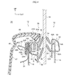
- FIG. 1 A front side door, to which the vehicle door structure relating to the present embodiment is applied, is shown in Fig. 1 in a state of being viewed from the vehicle inner side. Further, a vertical sectional view of the front side door along line 2-2 in Fig. 1 is shown in Fig. 2 .
- a front side door 10 that serves as a vehicle door is provided at the side portion (not shown) of a vehicle. The front side door 10 is mounted, so as to be able to open and close, to a front door opening portion (not illustrated) that is provided in the side portion of the vehicle.
- the front side door 10 has a door main body 12 that is structured to include a door outer panel 14, that is disposed at the vehicle transverse direction outer side, and a door inner panel 16, that is disposed at the vehicle transverse direction inner side.
- the door outer panel 14 and the door inner panel 16 are formed in a closed cross-sectional structure due to the end edge portion, other than an upper edge portion 14A, of the door outer panel 14 being made integral by hemming processing with an end edge portion 16B, other than an upper edge portion 16A, of the door inner panel 16.
- a vehicle door structure 28 of the present embodiment is applied to the front side door 10.
- the front side door 10 has a door glass (side door glass) 18 that is inserted into the interior of the door main body 12 (between the door outer panel 14 and the door inner panel 16) from the gap between the opposing portions of the upper edge portion 14A of the door outer panel 14 and the upper edge portion 16A of the door inner panel 16, and is disposed so as to be able to be raised and lowered in the vehicle vertical direction.
- a door frame 20, for guiding the door glass 18 at times of being raised and lowered, is mounted in the shape of a gate as seen from the vehicle side surface to the vehicle upper portion side of the door main body 12.
- the door main body 12 supports the door glass 18, that is disposed at the inner side of the door frame 20 as seen from the vehicle side surface, such that the door glass 18 can be raised and lowered.
- a door inner reinforcement 24 is disposed at the vehicle transverse direction inner side of the upper portion of the door inner panel 16.
- the upper edge portion 16A of the door inner panel 16 and a vertical wall portion 24A, that is formed at the upper end of the door inner reinforcement 24, are joined by welding or the like in a planarly-contacting state.
- an inner weatherstrip 30 that serves as an example of a sealing member is mounted by plural clips 40 to the joined portion of the upper edge portion 16A of the door inner panel 16 and the vertical wall portion 24A of the door inner reinforcement 24.
- a door trim 46 is mounted to the vehicle transverse direction inner side (a vehicle cabin 26 side) of the door main body 12 so as to cover the vehicle inner side surfaces of the door inner panel 16 and the door inner reinforcement 24 from the upper end portions of the door inner panel 16 and the door inner reinforcement 24 and the inner weatherstrip 30.
- the clip 40 is made of metal, and has a nipping portion 40A whose cross-section is substantially U-shaped and that opens toward the vehicle lower side.
- the nipping portion 40A of the clip 40 is formed from a plate spring that is elastically deformable in a direction intersecting the upper edge portion 16A of the door inner panel 16, and the nipping portion 40A is fit-in from the vehicle upper side of the joined portion of the upper edge portion 16A of the door inner panel 16 and the vertical wall portion 24A of the door inner reinforcement 24.
- a bent portion 40B whose cross-section is substantially U-shaped and that opens toward the vehicle upper side, is formed at the wall portion at the vehicle inner side of the nipping portion 40A of the clip 40 so as to be continuous with this wall portion at the vehicle inner side.
- a vertical wall 32B at the vehicle inner side of a mounting portion 32 of the inner weatherstrip 30 that is described later is inserted in the bent portion 40B.
- the nipping portion 40A of the clip 40 is fixed to the joined portion of the upper edge portion 16A of the door inner panel 16 and the vertical wall portion 24A of the door inner reinforcement 24.
- a bent portion 40C that is bent so as to project-out toward the vehicle inner side, is formed at the upper end portion of the vehicle inner side of the bent portion 40B of the clip 40.
- An engaging portion is formed at the distal end of the bent portion 40C, and an opening portion (not illustrated) that is formed in the door trim 46 is engaged.
- the inner weatherstrip 30 is an elongated member that is provided along the vehicle longitudinal direction at the upper portion of the door inner panel 16.
- the inner weatherstrip 30 has the mounting portion 32 whose cross-section is substantially U-shaped and in which an opening is formed at the vehicle lower side, a wall body 34 that, together with a vertical wall 32A at the vehicle outer side of the mounting portion 32, forms a closed space S that is substantially rectangular, two sealing lips 36 that extend so as to project-out toward the door glass 18 side from a vertical wall (wall) 34A that forms the wall at the vehicle outer side of the wall body 34, and through-holes 38 that serve as examples of an opening and that are formed in the vertical wall 34A between the two sealing lips 36.
- the mounting portion 32 of the inner weatherstrip 30 is mounted to the joined portion of the upper edge portion 16A of the door inner panel 16 and the vertical wall portion 24A of the door inner reinforcement 24, by the clips 40 in a state of being inserted onto the exterior of the nipping portions 40A of the clips 40.
- the vertical wall (wall) 34A of the wall body 34 is disposed so as to face the door glass 18, in the state in which the mounting portion 32 of the inner weatherstrip 30 is mounted to the joined portion of the upper edge portion 16A of the door inner panel 16 and the vertical wall portion 24A of the door inner reinforcement 24.
- the two sealing lips 36 are formed in parallel at the vehicle upper and lower sides at the vertical wall 34A.
- the vertical wall 34A and the two sealing lips 36 are disposed along the vehicle longitudinal direction of the door main body 12.
- the two sealing lips 36 extend in a direction intersecting the locus on which the door glass 18 is raised and lowered, and the distal ends of the two sealing lips 36 are directed toward the vehicle diagonally upper side with respect to the wall surface of the vertical wall 34A.
- the two sealing lips 36 can elastically deform in a direction intersecting the direction in which the distal ends thereof extend. Further, the sealability with the door glass 18 is ensured due to the distal ends of the sealing lips 36 slidingly contacting the door glass 18.
- the through-holes (openings) 38 are formed in a vicinity of the sealing lips 36 at positions, that face the door glass 18, of the vertical wall 34A.
- the through-holes 38 are provided at a position that overlaps the distal end portion of the sealing lip 36 that is at the vehicle lower side.
- the plural through-holes 38 are formed along the longitudinal direction of the vertical wall 34A (the vehicle longitudinal direction) between the two sealing lips 36 (see Fig. 3 ).
- the plural through-holes 38 are made to be circular shapes of substantially the same size.
- the wall body 34 that communicates with the through-holes 38 and forms the closed space S, is provided at the side of the vertical wall 34A opposite the door glass 18, and the vertical wall 34A is formed integrally with the wall body 34.
- the wall body 34, that forms the closed space S is disposed at the rear of the through-holes 38 of the vertical wall 34A, with respect to the door glass 18.
- the wall body 34 that forms the closed space S is disposed along the vehicle longitudinal direction at the vehicle transverse direction outer side of the door inner panel 16 at the interior of the door main body 12 (see Fig. 3 ).
- the mounting portion 32 and the wall body 34 and the two sealing lips 36 of the inner weatherstrip 30 are molded integrally from an elastic member of rubber or resin or the like (in the present embodiment, rubber).
- the inner weatherstrip 30 is formed by extrusion molding. Due thereto, the wall body 34, that has the closed space S that communicates with the through-holes 38, can be formed easily at the inner weatherstrip 30. Further, two projecting pieces 30A, 30B that abut the door trim 46 are formed at the upper portion of the wall body 34 of the inner weatherstrip 30, and two projecting pieces 30C that abut the clips 40 and the door inner panel 16 are formed at the vehicle inner side of the vertical wall 32A of the mounting portion 32.
- An upper end portion 47A of a base material 47 of the door trim 46 is disposed so as to circle-in from the vehicle upper side of the inner weatherstrip 30 toward the vehicle transverse direction inner side.
- a skin 48 is provided at the door trim 46 so as to cover the upper surface and the side surface portion at the outer side in the vehicle transverse direction of the base material 47. Due to the projecting pieces 30A, 30B of the inner weatherstrip 30 abutting the reverse surface side of the door trim 46, the sealability of the inner weatherstrip 30 and the door trim 46 is ensured. Further, due to the projecting pieces 30C of the inner weatherstrip 30 abutting the door inner panel 16 and the clips 40, the sealability of the inner weatherstrip 30 and the door inner panel 16 is ensured.
- a belt molding 50 that is made of rubber or resin and that is disposed along the vehicle longitudinal direction of the door main body 12, is mounted to the upper edge portion 14A of the door outer panel 14.
- the belt molding 50 has a mounting portion 52 that opens toward the vehicle lower side and that is fit into the upper edge portion 14A of the door outer panel 14, and two sealing lips 54 that project-out toward the door glass 18 side from a vertical wall 52A at the vehicle inner side that structures the mounting portion 52.
- the two sealing lips 54 are disposed in parallel at the vehicle upper and lower sides.
- the two sealing lips 54 extend in a direction intersecting the locus on which the door glass 18 is raised and lowered, and, due to the distal ends of the sealing lips 54 slidingly contacting the door glass 18, the sealability with the door glass 18 is ensured.
- two projecting pieces 50A that abut the door outer panel 14 are formed at the vehicle outer side of the vertical wall 52A of the mounting portion 52. Due to the projecting pieces 50A abutting the door outer panel 14, the sealability of the belt molding 50 and the door outer panel 14 is ensured.
- the wall body 34 of the inner weatherstrip 30 is shown in Fig. 6 in a lateral sectional view along the vehicle longitudinal direction.
- the plural through-holes 38 are formed along the longitudinal direction of the inner weatherstrip 30, in the vertical wall 34A, that faces the door glass 18 (see Fig. 2 ), at the wall body 34.
- the wall body 34 that forms the closed space S that communicates with the plural through-holes 38, is provided at the side of the vertical wall 34A opposite the door glass 18.
- Virtual walls 34B that are orthogonal to the vertical wall 34A and that divide the wall body 34 interior, are disposed at the interior of the wall body 34 between the adjacent through-holes 38. Due to these virtual walls 34B, spaces S1, that communicate with the respective through-holes 38 respectively, are formed at the rear of the vertical wall 34A (the side opposite the door glass 18).
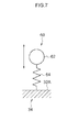
- a spring-mass system 60 that has one degree of freedom and in which the air at the through-hole 38 portion is a mass 62 and the space S1 formed by the virtual walls 34B and the wall body 34 at the rear of the vertical wall 34A is a spring 64, is structured at this inner weatherstrip 30.
- this spring-mass system 60 of one degree of freedom when sound of a specific frequency hits the mass 62 of air at the through-hole 38 portion, the mass 62 vibrates severely in the expanding/contracting direction of the spring 64 (the direction that is orthogonal to the vertical wall 32A of the wall body 34 and is shown by the arrow). Due thereto, the energy of the sound changes into vibration energy, and further, due to the vibration energy changing into thermal energy due to the viscous resistance and friction of the air, sound of the specific frequency is reduced markedly.
- the frequency at which the sound reducing effect appears is determined by the size of the through-hole 38 and the volume (capacity) of the space S1 the rear of the through-hole 38.
- the spring-mass system 60 of one degree of freedom sound is markedly reduced when the spring-mass system 60 resonates (is markedly reduced at the specific frequency).
- frequencies 66A, 66B, 66C at which a sound reducing effect appears are varied.
- a vehicle door structure 70 relating to a first modified example is shown in Fig. 9 . Note that the same structural portions as the first embodiment are denoted by the same numbers, and description thereof is omitted.
- a wall body 74 that forms the closed space S that is larger than that of the wall body 34 of the first embodiment (see Fig. 2 ), is formed integrally with a vertical wall 74A at the reverse surface side of the vertical wall 74A that faces the door glass 18.
- the two sealing lips 36 are provided at this inner weatherstrip 72, and the through-holes 38 are formed in the vertical wall 74A in a vicinity of the lower side of the sealing lip 36 that is at the lower side.
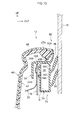
- a vehicle door structure 80 relating to a second modified example is shown in Fig. 10 . Note that the same structural portions as the first embodiment are denoted by the same numbers, and description thereof is omitted.
- the wall body 74 that forms the closed space S that is larger than that of the wall body 34 of the first embodiment (see Fig. 2 ), is formed integrally with the vertical wall 74A at the reverse surface side of the vertical wall 74A that faces the door glass 18.
- the two sealing lips 36 are provided at this inner weatherstrip 82, and the through-holes 38 are formed in the vertical wall 74A in a vicinity of the upper side of the sealing lip 36 that is at the upper side.
- the through-holes 38 are provided at a position that overlaps the sealing lip 36 at the upper side, as seen from the vehicle side surface.
- a vehicle door structure 900 relating to a comparative example is shown in Fig. 26 .
- an inner weatherstrip 902 that has a mounting portion 904 whose cross-section is substantially U-shaped and in which an opening is formed at the vehicle lower side, is provided at a front side door 910 to which this vehicle door structure 900 is applied.
- the mounting portion 904 is mounted by plural clips (see Fig. 27 ) to the joined portion of the upper edge portion 16A of the door inner panel 16 and the vertical wall portion 24A of the door inner reinforcement 24.
- the two sealing lips 36 that extend to as to project-out toward the door glass 18 side, are provided in parallel at the vehicle upper and lower sides at a vertical wall 904A at the vehicle outer side of the mounting portion 904.
- the distal ends of the sealing lips 36 slidingly contact the door glass 18. Note that through-holes and a closed space at the rear thereof are not provided at the vertical wall 904A, that faces the door glass 18, at the inner weatherstrip 902.
- the distal ends of the sealing lips 36 abut the inner wall surface of the door glass 18, but the distal ends of the sealing lips 36 cannot be strongly pushed against the door glass 18, and there is the possibility that the sound-insulating performances of the contact points of the sealing lips 36 and the door glass 18 will deteriorate. Therefore, there is the possibility that sound at the exterior of the front side door 910 (noise at the vehicle exterior, and the like) will penetrate into the vehicle cabin from the gaps between the distal ends of the sealing lips 36 and the door glass 18, as shown by arrow 906.
- the spring-mass system 60 having one degree of freedom is structured by providing the through-holes 38 in the vertical wall 74A at the lower side of the two sealing lips 36, and by providing the wall body 74 that forms the closed space S at the rear of the through-holes 38.
- the spring-mass system 60 having one degree of freedom is structured by providing the through-holes 38 in the vertical wall 74A at the lower side of the two sealing lips 36, and by providing the wall body 74 that forms the closed space S at the rear of the through-holes 38.
- the spring-mass system 60 having one degree of freedom see Fig.
- FIG. 7 is structured by providing the through-holes 38 in the vertical wall 74A at the upper side of the two sealing lips 36, and by providing the wall body 74 that forms the closed space S at the rear of the through-holes 38. Accordingly, as shown in Fig. 7 , when sound of a specific frequency hits the mass 62 that is the air at the through-hole 38 portion, the mass 62 vibrates in the expanding/contracting direction of the spring 64. Due thereto, the energy of the sound changes into vibration energy, and further, due to the vibration energy changing into thermal energy due to the viscous resistance and friction of the air, sound of the specific frequency is markedly reduced.
- Fig. 11 is a graph showing the relationship between frequency and the sound reducing effect.
- the case of the vehicle door structure 900 of the comparative example (see Fig. 26 ) is shown by line 86
- the cases of the vehicle door structures 70, 80 of the first modified example and the second modified example (see Fig. 9 , Fig. 10 ) are shown by line 84.
- the sound reducing effect at a specific frequency is great as compared with the vehicle door structure 900 of the comparative example.
- Fig. 12 the relationship between frequency and the sound reducing effect in the case of the vehicle door structure 28 of the first embodiment (see Fig. 2 and the like) is shown by line 88.
- Fig. 12 in the vehicle door structure 28 of the first embodiment (see Fig. 2 and the like), by forming the through-holes 38 in the vertical wall 34A between the two sealing lips 36 that are at the vehicle upper and lower sides of the inner weatherstrip 30, the frequency range in which sound is reduced is wide as compared with the vehicle door structures of the first modified example and the second modified example (see Fig. 9 , Fig. 10 ).
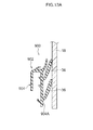
- Fig. 13A in the vehicle door structure 900 of the comparative example, the distal ends of the two sealing lips 36 at the vehicle upper and lower sides of the inner weatherstrip 902 abut the door glass 18.
- Fig. 13B there is a structure in which the sealing lip 36 at the upper side and the sealing lip 36 at the lower side within a wall body 920 are connected by two upper and lower springs 924 that are connected at a connection point 922 at the central portion.
- the inner weatherstrip 30 that has the through-holes 38, that are formed in the vertical wall 34A between the two sealing lips 36 that abut the door glass 18, and the wall body 34 that forms the closed space S at the rear of the through-holes 38.
- Fig. 14B there is a structure in which the wall body 34 that is formed by the vehicle door structure 28 is connected to the wall body 920 that is formed by the vehicle door structure 900. Namely, the wall body 34 is connected to the wall body 920 via the through-holes 38 of the vertical wall 34A.
- the air of the through-hole 38 portion that is formed in the vertical wall 34A is the mass 62, and the spring 64 that is the closed space S of the wall body 34 and one end of a spring 90 that is the closed space of the wall body 920 are connected to this mass 62, and the other end of the spring 90 is connected to the connection point 922.
- the energy of the sound changes into vibration energy, and further, due to the vibration energy changing into thermal energy due to the viscous resistance and the friction of the air, sound of the specific frequency is markedly reduced.
- the spring-mass system 930 has vertical symmetry, it is equivalent to a spring-mass system of one degree of freedom, and therefore, the spring-mass system 92 is equivalent to a spring-mass system of two degrees of freedom. Therefore, as shown in Fig. 12 , the line 88 of the sound reducing effect has resonance of two peaks, and a sound reducing effect can be obtained in a wide range of frequencies.
- the results of measuring the sound pressure level at the door inner side with respect to frequency, for the vehicle door structure 28 of the present embodiment, the vehicle door structure 70 of the first modified example and the vehicle door structure 900 of the comparative example, are shown in Fig. 15 .
- the sound pressure level in accordance with the vehicle door structure 28 is shown by solid line 94A
- the sound pressure level in accordance with the vehicle door structure 70 is shown by dotted line 94B
- the sound pressure level in accordance with the vehicle door structure 900 is shown by two-dot chain line 94C.
- the sound pressure level was substantially the same as the dotted line 94B. Accordingly, a sound reducing effect appears in a wide range of frequencies by utilizing the vehicle door structure 28 in which the through-holes 38 are formed in the vertical wall 34A between the two sealing lips 36 that abut the door glass 18. Therefore, the effect of insulating sounds that penetrate from the vehicle exterior into the vehicle cabin 26 can be improved.
- FIG. 16 A second embodiment of the vehicle door structure relating to the present invention is described next by using Fig. 16 . Note that the same structural portions as the above-described first embodiment are denoted by the same numbers, and description thereof is omitted.
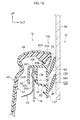
- the through-holes 38 are formed in the vertical wall 34A that faces the door glass 18, and the wall body 34 that forms a closed space is provided at the rear of the through-holes 38 (at the side opposite the door glass 18).
- a partitioning wall 104 that is disposed along the vehicle transverse direction and divides the closed space, is provided at the interior of the wall body 34.
- Through-holes 106 that serve as examples of another opening, are provided in the central portion of the partitioning wall 104.
- a space S2 is provided by the wall body 34 and the partitioning wall 104 at the rear of the through-holes 38 that are formed in the vertical wall 34A (at the side opposite the door glass 18), and further, another closed space S3 is provided by the wall body 34 and the partitioning wall 104 at the deep side (the side opposite the closed space S2) of the through-holes 106 that are formed in the partitioning wall 104.
- the wall body 34 of the inner weatherstrip 102 is a double structure via the partitioning wall 104 that is provided with the through-holes 106, and the through-holes 38 and the space S2 and the through-holes 106 and the closed space S3 are connected in series.
- the through-holes 106 are made to be circular shapes of substantially the same size as the through-holes 38.
- the inner weatherstrip 102 is molded integrally of an elastic member of rubber or resin or the like. Due thereto, the wall body 34 that has the vertical wall 34A and the partitioning wall 104 can be manufactured easily.
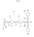
- a spring-mass system 122 of one degree of freedom in which the air of the through-hole 106 portion that is formed in the partitioning wall 104 is a mass 114 and the closed space S3 at the deep side of the through-hole 106 is a spring 116.
- a spring-mass system 110 in which the spring-mass system 60, that has one degree of freedom and in which the air of the through-hole 38 portion is the mass 62 and the space S2 at the rear of the through-hole 38 is the spring 64, and the spring-mass system 122, that has one degree of freedom and is formed by the mass 114 and the spring 116, are connected in series to the spring-mass system 930 that is structured by the two upper and lower sealing lips 36. Due thereto, the trough between the two peaks of line 88 of the sound reducing effect shown in Fig. 12 becomes gradual, and the portion where the sound reducing effect weakens between the two peaks becomes smaller. Therefore, a sound reducing effect in a wide range of frequencies can be obtained more reliably.
- the partitioning wall 104 is provided in the vehicle transverse direction (lateral direction) at the interior of the wall body 34, but the present invention is not limited to this.
- a partitioning wall may be provided in the vertical direction at the interior of the wall body 34, and through-holes may be provided in this partitioning wall. Namely, it suffices for there to be a structure in which the space S2 is formed at the rear of the through-holes 38 that are formed in the vertical wall 34A, and the other closed space S3 is provided at the deep side of the through-holes 106 of the partitioning wall that contacts the space S2.
- the one partitioning wall 104 is provided at the interior of the wall body 34, but the present invention is not limited to this.
- Plural partitioning walls may be provided, and through-holes may be formed in each of the partitioning walls. Namely, larger numbers of partitioning walls and through-holes are more preferable. Due thereto, a sound reducing effect in a wide range of frequencies can be obtained more reliably.
- FIG. 18 A third embodiment of the vehicle door structure relating to the present invention is described next by using Fig. 18 . Note that the same structural portions as the above-described first embodiment and second embodiment are denoted by the same numbers, and description thereof is omitted.
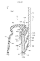
- two through-holes (openings) 134, 136 are provided in parallel in the vertical direction between the two sealing lips 36 at the vertical wall 34A that faces the door glass 18.
- the wall body 34 that forms a closed space is provided at the rear of the through-holes 134, 136 (the side opposite the door glass 18).
- a virtual wall 138 is disposed along the vehicle transverse direction between the through-holes 134, 136 and within the wall body 34. Namely, due to the virtual wall 138, the closed space within the wall body 34 is divided, and a space S4 is formed at the rear of the through-hole 134, and a space S5 is formed at the rear of the through-hole 134.
- this vehicle door structure 130 there is a structure in which a spring-mass system, that has one degree of freedom and is structured by the through-hole 134 and the space S4, and a spring-mass system, that has one degree of freedom and is structured by the through-hole 136 and the space S5, are disposed in parallel with the spring-mass system 930 (see Fig. 17 ) that is structured by the two upper and lower sealing lips 36. Due thereto, a sound reducing effect in a wide range of frequencies can be obtained more reliably.
- the two through-holes 134, 136 are provided in the vertical direction between the two sealing lips 36 at the vertical wall 34A.
- the present invention is not limited to this, and three or more through-holes may be provided in the vertical direction.
- FIG. 19 A fourth embodiment of the vehicle door structure relating to the present invention is described next by using Fig. 19 . Note that the same structural portions as the above-described first through third embodiments are denoted by the same numbers, and description thereof is omitted.
- a mounting portion 154 whose cross-section is substantially U-shaped and at which an opening is formed at the vehicle lower side, is provided.
- the mounting portion 154 is fit-in at the joined portion of the upper edge portion 16A of the door inner panel 16 and the vertical wall portion 24A of the door inner reinforcement 24, and is fixed by plural clips (not shown).
- a vertical wall 154A at the vehicle outer side of the mounting portion 154 is disposed so as to face the door glass 18, and the two sealing lips 36 are provided at the outer side surface in the vehicle transverse direction of the vertical wall 154A.
- the through-holes 38 are formed between the two sealing lips 36 of the vertical wall 154A.
- Lip portions 152A, 152B that abut the upper edge portion 16A of the door inner panel 16 at the upper side and the lower side of the through-holes 38 (at the side opposite the two sealing lips 36), are formed at the inner side surface in the vehicle transverse direction of the vertical wall 154A.
- the lip portions 152, 152B are provided so as to close the space at rear of the through-holes 38 (the side opposite the door glass 18).
- the closed space S is formed at the rear of the through-holes 38 of the vertical wall 154A by the wall body that is structured by the vertical wall 154A and the upper and lower lip portions 152A, 152B and the upper edge portion 16A of the door inner panel 16. Due thereto, a spring-mass system, in which the air at the through-hole 38 portion is a mass and the closed space S at the rear of the through-hole 38 is a spring, is formed.
- the closed space S can be formed at the rear of the through-holes 38 even if the position of the door inner panel 16 is not changed with respect to the vehicle door structure 900 of the comparative example. Accordingly, sound can be reduced effectively even in cases in which there are constraints on space due to other parts. Therefore, the effect of insulating sounds that penetrate from the vehicle exterior into the vehicle cabin can be improved.
- FIG. 20 A fifth embodiment of the vehicle door structure relating to the present invention is described next by using Fig. 20 . Note that the same structural portions as the above-described first through fourth embodiments are denoted by the same numbers, and description thereof is omitted.
- the mounting portion 154 is provided at an inner weatherstrip 162, and the through-holes 38 are formed in the vertical wall 154A at the vehicle outer side of the mounting portion 154.
- a door inner panel 164 has a lateral wall portion 164A that is bent toward the vehicle transverse direction outer side at the lower portion side of the upper edge portion 16A, and a vertical wall portion 164B that is bent toward the vehicle lower side from the vehicle transverse direction outer side end portion of the lateral wall portion 164A.
- a door inner reinforcement 166 has a lateral wall portion 166A that is bent toward the vehicle transverse direction inner side at the lower portion side of the vertical wall portion 24A at the upper end, and a vertical wall portion 166B that is a curved shape and is bent toward the vehicle lower side from the vehicle transverse direction inner side end portion of the lateral wall portion 166A.
- the lower end portion of the vertical wall 154A at the vehicle outer side contacts the lateral wall portion 164A of the door inner panel 164
- the lower end portion of a vertical wall 154B at the vehicle inner side contacts the lateral wall portion 166A of the door inner reinforcement 166.
- the lateral wall portion 164A of the door inner panel 164 and the lateral wall portion 166A of the door inner reinforcement 166 are provided in order to close the space at the rear of the through-holes 38.
- the closed space S is formed at the rear of the through-holes 38 of the vertical wall 154A, by the wall body that is structured by the mounting portion 154 and the door inner panel 164 and the door inner reinforcement 166. Accordingly, a spring-mass system, in which the air at the through-hole 38 portion is a mass and the closed space S at the rear of the through-hole 38 is a spring, is structured.
- FIG. 21 A sixth embodiment of the vehicle door structure relating to the present invention is described next by using Fig. 21 . Note that the same structural portions as the above-described first through fifth embodiments are denoted by the same numbers, and description thereof is omitted.
- a substantially U-shaped mounting portion 174 is provided at an inner weatherstrip 172, and the mounting portion 174 is fit-in at the joined portion of the upper edge portion 16A of the door inner panel 16 and the vertical wall portion 24A of the door inner reinforcement 24, and is fixed by plural clips (not shown).
- a vertical wall 174A at the vehicle outer side of the mounting portion 174 is disposed so as to face the door glass 18, and the three sealing lips 36 are provided in the vertical direction at the outer side surface in the vehicle transverse direction of the vertical wall 174A.
- the through-holes 38 are formed respectively between the three sealing lips 36 of the vertical wall 174A.
- Lip portions 172A, 172B that abut the upper edge portion 16A of the door inner panel 16 at the upper side and the lower side with respect to the two through-holes 38, are formed at the inner side surface in the vehicle transverse direction of the vertical wall 174A.
- the lip portions 172A, 172B are provided so as to close the space at the rear (the side opposite the door glass 18) of the two through-holes 38.
- the closed space S is formed at the rear of the through-holes 38 that are provided in the vertical wall 174A, by the wall body that is structured by the vertical wall 174A and the upper and lower lip portions 172A, 172B and the upper edge portion 16A of the door inner panel 16. Due thereto, the number of sealing lips 36 is increased, and the through-holes 38 can be opened between these sealing lips 36, and sound can be reduced more effectively by the spaces at the rear of the respective through-holes 38. Therefore, the effect of insulating sounds that penetrate from the vehicle exterior into the vehicle cabin can be improved more reliably.
- the number of sealing lips 36 may be increased further, and through-holes may be provided between the respective sealing lips 36.
- the sound insulating effect can be improved further.
- FIG. 22 A seventh embodiment of the vehicle door structure relating to the present invention is described next by using Fig. 22 . Note that the same structural portions as the above-described first through sixth embodiments are denoted by the same numbers, and description thereof is omitted.
- a belt molding 192 that serves as an example of a sealing member is fixed by plural clips or the like to the upper edge portion 14A of the door outer panel 14.
- the belt molding 192 has a mounting portion 194 that opens toward the vehicle lower side and is fit-in at the upper edge portion 14A of the door outer panel 14, and the two sealing lips 54 that project-out toward the door glass 18 side from a vertical wall 194A at the vehicle transverse direction inner side that structures the mounting portion 194.
- the distal end portions of the two sealing lips 54 are directed toward the vehicle diagonally upper side with respect to the wall surface of the vertical wall 194A.
- the through-holes 38 are formed in the vertical wall 194A between the two sealing lips 54.
- the through-holes 38 are provided in a vicinity of the two sealing lips 54, at a position that overlaps with the distal end portion of the sealing lip 54 at the lower side.
- the two projecting pieces 50A that abut the door outer panel 14 are formed at the belt molding 192 at the upper side and the lower side of the through-holes 38 at the vehicle outer side surface of the vertical wall 194A. Due thereto, the closed space S is formed at the rear (the side opposite the door glass 18) of the through-holes 38.
- the inner weatherstrip 902 that is the same as that of the vehicle door structure 900 of the comparative example is used.
- the closed space S is formed at the rear of the through-holes 38 of the vertical wall 194A, by the wall body that is structured by the vertical wall 194A and the upper and lower projecting pieces 50A and the upper edge portion 14A of the door outer panel 14. Due thereto, a spring-mass system, in which the air at the through-hole 38 portion is a mass and the closed space S at the rear of the through-hole 38 is a spring, is structured, and sound of a specific frequency can be reduced. Therefore, the effect of insulating sounds that penetrate from the vehicle exterior into the vehicle cabin can be improved.
- FIG. 23 through Fig. 25 An eighth embodiment of the vehicle door structure relating to the present invention is described next by using Fig. 23 through Fig. 25 . Note that the same structural portions as the above-described first through seventh embodiments are denoted by the same numbers, and description thereof is omitted.
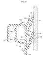
- the through-holes 38 that are formed between the two sealing lips 36 at the vertical wall 34A that faces the door glass 18, and a canopy 204, that projects-out toward the vehicle transverse direction outer side from the vertical wall 34A at the upper side of the through-holes 38, are provided.
- the canopy 204 is formed so as to be inclined slightly toward the vehicle lower side with respect to the outer wall surface of the vertical wall 34A.
- the canopy 204 is provided at the upper side of the through-holes 38, and therefore, the water droplets 206, that have flowed along the lower surface of the sealing lip 36, flow on the upper surface of the canopy 204, and further, the water droplets 206 drop-off from the distal end of the canopy 204 onto the sealing lip 36 at the lower side, and collect between this sealing lip 36 and the vertical wall 34A.
- the water droplets 206 flowing into the through-holes 38 from the vertical wall 34A and collecting in the closed space S at the interior of the wall body 34 can be impeded.
- the plural through-holes 38 that are formed in the vertical wall that faces the door glass 18 are made to be circular shapes of substantially the same size (see Fig. 3 ).
- the plural through-holes (openings) may be made to be different sizes. Because the frequency at which the sound reducing effect appears is determined by the size of the through-holes and the volume of the closed space, there may be a structure in which the size of the plural through-holes is varied in plural stages (e.g., three stages that are large, medium, small) in order to reduce sounds of different frequencies.
- the through-holes are made to be circular shapes, they may be made to be another shape such as triangular, quadrangular, polygonal, or the like. Note that, although the shape of the through-holes does not matter, in terms of manufacturing, circular is preferable in order to open the through-holes in the trim.
- the shape of the wall body that forms the closed space at the rear of the through-holes is not particularly limited, and may be spherical or a polygonal body or the like for example.
- the closed space is formed by connecting a duct from the through-holes of the vertical wall that faces the door glass 18.
- the vehicle door structure is provided at a front side door, but the present invention is not limited to the same and can be applied to another vehicle door such as a rear side door or the like.
Landscapes
- Engineering & Computer Science (AREA)
- Mechanical Engineering (AREA)
- Seal Device For Vehicle (AREA)
- Vehicle Interior And Exterior Ornaments, Soundproofing, And Insulation (AREA)
- Soundproofing, Sound Blocking, And Sound Damping (AREA)
Abstract
Description
- The present invention relates to a vehicle door structure.
-
Patent Document 1 that is mentioned hereinafter discloses a structure in which an inner weatherstrip, that has two sealing lips that slidingly contact the inner surface of a door glass, is disposed at the vehicle inner side of the door glass at the interior of a side door.
[Patent Document 1] Japanese Patent Application Laid-Open No.2010-149579 - In a case in accordance with
aforementioned Patent Document 1, in order to decrease the sliding resistance of the door glass, the pressing force of the sealing lips against the door glass must be reduced. When the pressing force of the sealing lips against the door glass is set to be low, there is the possibility that the sound-insulating effect of insulating sounds that penetrate into the vehicle cabin from the vehicle exterior will deteriorate. - In consideration of the above-described circumstances, an object of the present invention is to provide a vehicle door structure that can improve the sound-insulating effect. Solution to Problem
- A vehicle door structure of a first aspect relating to the present invention is a structure comprising: a door main body that supports a door glass such that the door glass can be raised and lowered; a sealing member that is provided at the door main body, and that has a wall in which an opening is formed at a position facing the door glass, and a sealing lip that is elastically deformable and is disposed so as to project out from the wall and slidingly contact the door glass; and a wall body that structures a portion of the door main body, and that, together with the wall, forms a closed space that communicates with the opening at a side of the wall opposite from the door glass.
- A vehicle door structure of a second aspect relating to the present invention is a structure in which, in the vehicle door structure of the first aspect, the sealing member has at least two sealing lips that are disposed in parallel at vehicle upper and lower sides, and the opening is provided between the sealing lips that are adjacent.
- A vehicle door structure of a third aspect relating to the present invention is a structure in which, in the vehicle door structure of the first aspect or the second aspect, the sealing member is an inner weatherstrip that is fit-together with an upper end portion of a door inner panel that structures a vehicle inner side member of the door main body, and the wall body is molded integrally with the inner weatherstrip.
- A vehicle door structure of a fourth aspect relating to the present invention is a structure in which, in the vehicle door structure of any one aspect of the first aspect through the third aspect, a canopy that projects out toward the door glass side is provided at an upper portion, in a vehicle vertical direction, of the opening at the wall.
- A vehicle door structure of a fifth aspect relating to the present invention is a structure in which, in the vehicle door structure of any one aspect of the first aspect through the fourth aspect, at least one partitioning wall that divides the closed space is provided at the wall body, and another opening is formed in the partitioning wall.
- In accordance with the vehicle door structure of the first aspect relating to the present invention, the wall, in which an opening is formed at a position facing the door glass, and a sealing lip, that projects out from the wall, are provided at the sealing member that is provided at the door main body, and the sealing lip slidingly contacts the door glass. The wall body, that structures a portion of the door main body and that, together with the wall of the sealing member, forms a closed space that communicates with the opening, is provided at a side of the wall of the sealing member opposite the door glass. Due thereto, there becomes a spring-mass system in which the air at the opening portion is a mass and the closed space at the rear of the opening is a spring, and, when sound of a specific frequency hits, the air at the opening portion vibrates markedly. Due thereto, the energy of the sound changes into vibration energy, and moreover, due to the vibration energy changing into thermal energy due to the viscous resistance and friction of the air, the sound is reduced. Therefore, sound of a specific frequency can be reduced, and the sound insulating effect can be improved.
- In accordance with the vehicle door structure of the second aspect relating to the present invention, the sealing member has at least two sealing lips that are disposed in parallel at vehicle upper and lower sides, and the opening is provided at the wall between sealing lips that are adjacent. Due thereto, a spring-mass system, that is formed by the opening and the closed space of the wall body at the rear of the opening, is added to the spring-mass system that is formed from the two sealing lips. Due thereto, it is possible to increase the frequency range in which sound is reduced, and the sound-insulating effect can be improved more reliably.
- In accordance with the vehicle door structure of the third aspect relating to the present invention, the sealing member is an inner weatherstrip that is fit-together with the upper end portion of a door inner panel that structures a vehicle inner side member of the door main body, and the wall body, that forms the closed space, is molded integrally with the inner weatherstrip. Due thereto, the wall body, that has the closed space that communicates with the opening, can be formed easily at the inner weatherstrip.
- In accordance with the vehicle door structure of the fourth aspect relating to the present invention, the canopy that projects out toward the door glass side is provided at the upper portion, in the vehicle vertical direction, of the opening at the wall of the sealing member. When water droplets are generated due to condensation or the like at the inner surface of the door glass, the water, that has been transmitted-in along the wall of the sealing member from the vehicle upper side, is blocked by the canopy. Therefore, water flowing from the opening into the closed space at the interior of the wall body can be suppressed.
- In accordance with the vehicle door structure of the fifth aspect relating to the present invention, at least one partitioning wall that divides the closed space is provided at the wall body. By forming another opening at the partitioning wall, a spring-mass system, that is formed by the other opening of the partitioning wall and the space at the rear of the other opening, is added to the spring-mass system that is formed by the opening that is formed in the wall and the space at the rear of the opening. Due thereto, it is possible to increase the frequency range in which sound is reduced, and the sound-insulating effect can be improved more effectively.
- In accordance with the vehicle door structure relating to the present invention, the sound-insulating effect can be improved.
-
-
Fig. 1 is a structural drawing showing a vehicle inner side of a front side door to which a vehicle door structure relating to a first embodiment is applied. -
Fig. 2 is a vertical sectional view showing the structure of the vehicle door structure along line 2-2 ofFig. 1 . -
Fig. 3 is a perspective view showing an inner weatherstrip that is used in the vehicle door structure relating to the first embodiment. -
Fig. 4 is a vertical sectional view showing a state in which the inner weatherstrip shown in -
Fig. 2 is mounted to an inner panel by a clip. -
Fig. 5 is a perspective view showing a state in which the clips are provided at the inner weatherstrip. -
Fig. 6 is a lateral sectional view showing a wall, in which through-holes are formed, and a wall body, that forms a closed space that communicates with the through-holes, at the inner weatherstrip. -
Fig. 7 is a drawing showing a spring-mass system that is formed by the through-hole shown in -
Fig. 6 and the closed space at the rear thereof. -
Fig. 8 is a graph showing the relationship between frequency and sound reducing effect. -
Fig. 9 is a vertical sectional view showing the structure of a vehicle door structure relating to a first modified example. -
Fig. 10 is a vertical sectional view showing the structure of a vehicle door structure relating to a second modified example. -
Fig. 11 is a graph showing the relationships between frequency and the sound reducing effect in the vehicle door structure relating to the first modified example or the second modified example and a vehicle door structure of a comparative example. -
Fig. 12 is a graph showing the relationships between frequency and the sound reducing effect in the vehicle door structure relating to the first embodiment, and the vehicle door structure relating to the first modified example or the second modified example, and the vehicle door structure of the comparative example. -
Fig. 13A is a vertical sectional view showing an inner weatherstrip and a door glass that are used in the vehicle door structure of the comparative example. -
Fig. 13B is a drawing showing, in a schematic manner, two sealing lips of the inner weatherstrip that is used in the vehicle door structure of the comparative example. -
Fig. 13C is a drawing showing a spring-mass system that is formed by the two sealing lips of the inner weatherstrip that is used in the vehicle door structure of the comparative example. -
Fig. 14A is a vertical sectional view showing the inner weatherstrip and the door glass that are used in the vehicle door structure relating to the first embodiment. -
Fig. 14B is a drawing showing, in a schematic manner, two sealing lips and the through-hole and the closed space of the inner weatherstrip that is used in the vehicle door structure relating to the first embodiment. -
Fig. 14C is a drawing showing a spring-mass system that is formed by the two sealing lips and a through-hole and a closed space of the inner weatherstrip that is used in the vehicle door structure of the comparative example. -
Fig. 15 is a graph showing the relationship between frequency and sound pressure level in the vehicle door structure relating to the first embodiment, and the vehicle door structure relating to the first modified example (the second modified example), and the vehicle door structure of the comparative example. -
Fig. 16 is a vertical sectional view showing the structure of a vehicle door structure relating to a second embodiment. -
Fig. 17 is a drawing showing a spring-mass system in the vehicle door structure shown inFig. 16 . -
Fig. 18 is a vertical sectional view showing the structure of a vehicle door structure relating to a third embodiment. -
Fig. 19 is a vertical sectional view showing the structure of a vehicle door structure relating to a fourth embodiment. -
Fig. 20 is a vertical sectional view showing the structure of a vehicle door structure relating to a fifth embodiment. -
Fig. 21 is a vertical sectional view showing the structure of a vehicle door structure relating to a sixth embodiment. -
Fig. 22 is a vertical sectional view showing the structure of a vehicle door structure relating to a seventh embodiment. -
Fig. 23 is a vertical sectional view showing the structure of a vehicle door structure relating to an eighth embodiment. -
Fig. 24 is an enlarged vertical sectional view showing a canopy above the through-hole of an inner weatherstrip that is used in the structure of the vehicle door structure shown inFig. 23 . -
Fig. 25 is a vertical sectional view showing a state in which water has been transmitted into a wall from above the inner weatherstrip that is used in the structure of the vehicle door structure shown inFig. 23 . -
Fig. 26 is a vertical sectional view showing the structure of the vehicle door structure relating to the comparative example. -
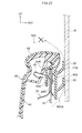
Fig. 27 is a vertical sectional view showing a state in which the sealing lips of the inner weatherstrip, that is used in the vehicle door structure relating to the comparative example, are pushed against the door glass. - A first embodiment of a vehicle door structure relating to the present invention is described hereinafter by using
Fig. 1 through Fig. 8 . Note that arrow FR that is shown appropriately in these drawings indicates the vehicle front side, arrow UP indicates the vehicle upper side, and arrow OUT indicates the vehicle transverse direction outer side. - A front side door, to which the vehicle door structure relating to the present embodiment is applied, is shown in
Fig. 1 in a state of being viewed from the vehicle inner side. Further, a vertical sectional view of the front side door along line 2-2 inFig. 1 is shown inFig. 2 . As shown in these drawings, afront side door 10 that serves as a vehicle door is provided at the side portion (not shown) of a vehicle. Thefront side door 10 is mounted, so as to be able to open and close, to a front door opening portion (not illustrated) that is provided in the side portion of the vehicle. Thefront side door 10 has a doormain body 12 that is structured to include a doorouter panel 14, that is disposed at the vehicle transverse direction outer side, and a doorinner panel 16, that is disposed at the vehicle transverse direction inner side. The doorouter panel 14 and the doorinner panel 16 are formed in a closed cross-sectional structure due to the end edge portion, other than anupper edge portion 14A, of the doorouter panel 14 being made integral by hemming processing with anend edge portion 16B, other than anupper edge portion 16A, of the doorinner panel 16. Avehicle door structure 28 of the present embodiment is applied to thefront side door 10. - Further, the
front side door 10 has a door glass (side door glass) 18 that is inserted into the interior of the door main body 12 (between the doorouter panel 14 and the door inner panel 16) from the gap between the opposing portions of theupper edge portion 14A of the doorouter panel 14 and theupper edge portion 16A of the doorinner panel 16, and is disposed so as to be able to be raised and lowered in the vehicle vertical direction. Adoor frame 20, for guiding thedoor glass 18 at times of being raised and lowered, is mounted in the shape of a gate as seen from the vehicle side surface to the vehicle upper portion side of the doormain body 12. Namely, the doormain body 12 supports thedoor glass 18, that is disposed at the inner side of thedoor frame 20 as seen from the vehicle side surface, such that thedoor glass 18 can be raised and lowered. - As shown in
Fig. 2 , a doorinner reinforcement 24 is disposed at the vehicle transverse direction inner side of the upper portion of the doorinner panel 16. Theupper edge portion 16A of the doorinner panel 16 and avertical wall portion 24A, that is formed at the upper end of the doorinner reinforcement 24, are joined by welding or the like in a planarly-contacting state. A projectingportion 24B, that is shaped as a curved surface and that projects-out toward the vehicle transverse direction inner side, is formed at the vehicle vertical direction intermediate portion of thevertical wall portion 24A of the doorinner reinforcement 24. - As shown in
Fig. 2 ,Fig. 4 andFig. 5 , at thevehicle door structure 28, aninner weatherstrip 30 that serves as an example of a sealing member is mounted byplural clips 40 to the joined portion of theupper edge portion 16A of the doorinner panel 16 and thevertical wall portion 24A of the doorinner reinforcement 24. Further, adoor trim 46 is mounted to the vehicle transverse direction inner side (avehicle cabin 26 side) of the doormain body 12 so as to cover the vehicle inner side surfaces of the doorinner panel 16 and the doorinner reinforcement 24 from the upper end portions of the doorinner panel 16 and the doorinner reinforcement 24 and theinner weatherstrip 30. - The
clip 40 is made of metal, and has a nippingportion 40A whose cross-section is substantially U-shaped and that opens toward the vehicle lower side. The nippingportion 40A of theclip 40 is formed from a plate spring that is elastically deformable in a direction intersecting theupper edge portion 16A of the doorinner panel 16, and the nippingportion 40A is fit-in from the vehicle upper side of the joined portion of theupper edge portion 16A of the doorinner panel 16 and thevertical wall portion 24A of the doorinner reinforcement 24. Further, abent portion 40B, whose cross-section is substantially U-shaped and that opens toward the vehicle upper side, is formed at the wall portion at the vehicle inner side of the nippingportion 40A of theclip 40 so as to be continuous with this wall portion at the vehicle inner side. Avertical wall 32B at the vehicle inner side of a mountingportion 32 of theinner weatherstrip 30 that is described later is inserted in thebent portion 40B. At this time, due to thevertical wall 32B of theinner weatherstrip 30 pushing the wall portion at the vehicle inner side of the nippingportion 40A in the direction of abutting the projectingportion 24B of thevertical wall portion 24A, the nippingportion 40A of theclip 40 is fixed to the joined portion of theupper edge portion 16A of the doorinner panel 16 and thevertical wall portion 24A of the doorinner reinforcement 24. Further, abent portion 40C, that is bent so as to project-out toward the vehicle inner side, is formed at the upper end portion of the vehicle inner side of thebent portion 40B of theclip 40. An engaging portion is formed at the distal end of thebent portion 40C, and an opening portion (not illustrated) that is formed in the door trim 46 is engaged. - As shown in
Fig. 2 through Fig. 4 , theinner weatherstrip 30 is an elongated member that is provided along the vehicle longitudinal direction at the upper portion of the doorinner panel 16. Theinner weatherstrip 30 has the mountingportion 32 whose cross-section is substantially U-shaped and in which an opening is formed at the vehicle lower side, awall body 34 that, together with avertical wall 32A at the vehicle outer side of the mountingportion 32, forms a closed space S that is substantially rectangular, two sealinglips 36 that extend so as to project-out toward thedoor glass 18 side from a vertical wall (wall) 34A that forms the wall at the vehicle outer side of thewall body 34, and through-holes 38 that serve as examples of an opening and that are formed in thevertical wall 34A between the two sealinglips 36. - The mounting
portion 32 of theinner weatherstrip 30 is mounted to the joined portion of theupper edge portion 16A of the doorinner panel 16 and thevertical wall portion 24A of the doorinner reinforcement 24, by theclips 40 in a state of being inserted onto the exterior of the nippingportions 40A of theclips 40. - The vertical wall (wall) 34A of the
wall body 34 is disposed so as to face thedoor glass 18, in the state in which the mountingportion 32 of theinner weatherstrip 30 is mounted to the joined portion of theupper edge portion 16A of the doorinner panel 16 and thevertical wall portion 24A of the doorinner reinforcement 24. The two sealinglips 36 are formed in parallel at the vehicle upper and lower sides at thevertical wall 34A. Thevertical wall 34A and the two sealinglips 36 are disposed along the vehicle longitudinal direction of the doormain body 12. The two sealinglips 36 extend in a direction intersecting the locus on which thedoor glass 18 is raised and lowered, and the distal ends of the two sealinglips 36 are directed toward the vehicle diagonally upper side with respect to the wall surface of thevertical wall 34A. The two sealinglips 36 can elastically deform in a direction intersecting the direction in which the distal ends thereof extend. Further, the sealability with thedoor glass 18 is ensured due to the distal ends of the sealinglips 36 slidingly contacting thedoor glass 18. - The through-holes (openings) 38 are formed in a vicinity of the sealing
lips 36 at positions, that face thedoor glass 18, of thevertical wall 34A. In the present embodiment, as seen from the vehicle side surface, the through-holes 38 are provided at a position that overlaps the distal end portion of the sealinglip 36 that is at the vehicle lower side. Further, the plural through-holes 38 are formed along the longitudinal direction of thevertical wall 34A (the vehicle longitudinal direction) between the two sealing lips 36 (seeFig. 3 ). In the present embodiment, the plural through-holes 38 are made to be circular shapes of substantially the same size. Thewall body 34, that communicates with the through-holes 38 and forms the closed space S, is provided at the side of thevertical wall 34A opposite thedoor glass 18, and thevertical wall 34A is formed integrally with thewall body 34. In other words, thewall body 34, that forms the closed space S, is disposed at the rear of the through-holes 38 of thevertical wall 34A, with respect to thedoor glass 18. Thewall body 34 that forms the closed space S is disposed along the vehicle longitudinal direction at the vehicle transverse direction outer side of the doorinner panel 16 at the interior of the door main body 12 (seeFig. 3 ). - In the present embodiment, the mounting
portion 32 and thewall body 34 and the two sealinglips 36 of theinner weatherstrip 30 are molded integrally from an elastic member of rubber or resin or the like (in the present embodiment, rubber). In the present embodiment, theinner weatherstrip 30 is formed by extrusion molding. Due thereto, thewall body 34, that has the closed space S that communicates with the through-holes 38, can be formed easily at theinner weatherstrip 30. Further, two projectingpieces wall body 34 of theinner weatherstrip 30, and two projectingpieces 30C that abut theclips 40 and the doorinner panel 16 are formed at the vehicle inner side of thevertical wall 32A of the mountingportion 32. - An
upper end portion 47A of abase material 47 of the door trim 46 is disposed so as to circle-in from the vehicle upper side of theinner weatherstrip 30 toward the vehicle transverse direction inner side. Askin 48 is provided at the door trim 46 so as to cover the upper surface and the side surface portion at the outer side in the vehicle transverse direction of thebase material 47. Due to the projectingpieces inner weatherstrip 30 abutting the reverse surface side of thedoor trim 46, the sealability of theinner weatherstrip 30 and the door trim 46 is ensured. Further, due to the projectingpieces 30C of theinner weatherstrip 30 abutting the doorinner panel 16 and theclips 40, the sealability of theinner weatherstrip 30 and the doorinner panel 16 is ensured. - As shown in
Fig. 2 andFig. 4 , abelt molding 50, that is made of rubber or resin and that is disposed along the vehicle longitudinal direction of the doormain body 12, is mounted to theupper edge portion 14A of the doorouter panel 14. Thebelt molding 50 has a mountingportion 52 that opens toward the vehicle lower side and that is fit into theupper edge portion 14A of the doorouter panel 14, and two sealinglips 54 that project-out toward thedoor glass 18 side from avertical wall 52A at the vehicle inner side that structures the mountingportion 52. The two sealinglips 54 are disposed in parallel at the vehicle upper and lower sides. The two sealinglips 54 extend in a direction intersecting the locus on which thedoor glass 18 is raised and lowered, and, due to the distal ends of the sealinglips 54 slidingly contacting thedoor glass 18, the sealability with thedoor glass 18 is ensured. - At the
belt molding 50, two projectingpieces 50A that abut the doorouter panel 14 are formed at the vehicle outer side of thevertical wall 52A of the mountingportion 52. Due to the projectingpieces 50A abutting the doorouter panel 14, the sealability of thebelt molding 50 and the doorouter panel 14 is ensured. - The
wall body 34 of theinner weatherstrip 30 is shown inFig. 6 in a lateral sectional view along the vehicle longitudinal direction. As shown inFig. 6 , the plural through-holes 38 are formed along the longitudinal direction of theinner weatherstrip 30, in thevertical wall 34A, that faces the door glass 18 (seeFig. 2 ), at thewall body 34. Thewall body 34, that forms the closed space S that communicates with the plural through-holes 38, is provided at the side of thevertical wall 34A opposite thedoor glass 18.Virtual walls 34B, that are orthogonal to thevertical wall 34A and that divide thewall body 34 interior, are disposed at the interior of thewall body 34 between the adjacent through-holes 38. Due to thesevirtual walls 34B, spaces S1, that communicate with the respective through-holes 38 respectively, are formed at the rear of thevertical wall 34A (the side opposite the door glass 18). - As shown in
Fig. 6 andFig. 7 , a spring-mass system 60, that has one degree of freedom and in which the air at the through-hole 38 portion is amass 62 and the space S1 formed by thevirtual walls 34B and thewall body 34 at the rear of thevertical wall 34A is aspring 64, is structured at thisinner weatherstrip 30. In this spring-mass system 60 of one degree of freedom, when sound of a specific frequency hits themass 62 of air at the through-hole 38 portion, themass 62 vibrates severely in the expanding/contracting direction of the spring 64 (the direction that is orthogonal to thevertical wall 32A of thewall body 34 and is shown by the arrow). Due thereto, the energy of the sound changes into vibration energy, and further, due to the vibration energy changing into thermal energy due to the viscous resistance and friction of the air, sound of the specific frequency is reduced markedly. - Here, given that the length of the through-
hole 38 is 1, the surface area of the through-hole 38 is S, the volume of the space S1 at the rear of the through-hole 38 is V, and the speed of sound is c, the reduction frequency f of the sound is expressed by the following formula.
- As shown by this formula, the frequency at which the sound reducing effect appears is determined by the size of the through-
hole 38 and the volume (capacity) of the space S1 the rear of the through-hole 38. As shown inFig. 8 , because there is the spring-mass system 60 of one degree of freedom, sound is markedly reduced when the spring-mass system 60 resonates (is markedly reduced at the specific frequency). Further, as shown inFig. 8 , by changing the size of the through-hole 38 and the volume (capacity) of the space S1 at the rear of the through-hole 38,frequencies - A
vehicle door structure 70 relating to a first modified example is shown inFig. 9 . Note that the same structural portions as the first embodiment are denoted by the same numbers, and description thereof is omitted. - As shown in
Fig. 9 , at aninner weatherstrip 72 to which thevehicle door structure 70 is applied, awall body 74, that forms the closed space S that is larger than that of thewall body 34 of the first embodiment (seeFig. 2 ), is formed integrally with avertical wall 74A at the reverse surface side of thevertical wall 74A that faces thedoor glass 18. The two sealinglips 36 are provided at thisinner weatherstrip 72, and the through-holes 38 are formed in thevertical wall 74A in a vicinity of the lower side of the sealinglip 36 that is at the lower side. - A
vehicle door structure 80 relating to a second modified example is shown inFig. 10 . Note that the same structural portions as the first embodiment are denoted by the same numbers, and description thereof is omitted. - As shown in
Fig. 10 , at an inner weatherstrip 82 to which thevehicle door structure 80 is applied, thewall body 74, that forms the closed space S that is larger than that of thewall body 34 of the first embodiment (seeFig. 2 ), is formed integrally with thevertical wall 74A at the reverse surface side of thevertical wall 74A that faces thedoor glass 18. The two sealinglips 36 are provided at this inner weatherstrip 82, and the through-holes 38 are formed in thevertical wall 74A in a vicinity of the upper side of the sealinglip 36 that is at the upper side. In the present embodiment, the through-holes 38 are provided at a position that overlaps the sealinglip 36 at the upper side, as seen from the vehicle side surface. - In contrast, a
vehicle door structure 900 relating to a comparative example is shown inFig. 26 . As shown inFig. 26 , aninner weatherstrip 902, that has a mountingportion 904 whose cross-section is substantially U-shaped and in which an opening is formed at the vehicle lower side, is provided at afront side door 910 to which thisvehicle door structure 900 is applied. The mountingportion 904 is mounted by plural clips (seeFig. 27 ) to the joined portion of theupper edge portion 16A of the doorinner panel 16 and thevertical wall portion 24A of the doorinner reinforcement 24. The two sealinglips 36, that extend to as to project-out toward thedoor glass 18 side, are provided in parallel at the vehicle upper and lower sides at avertical wall 904A at the vehicle outer side of the mountingportion 904. The distal ends of the sealinglips 36 slidingly contact thedoor glass 18. Note that through-holes and a closed space at the rear thereof are not provided at thevertical wall 904A, that faces thedoor glass 18, at theinner weatherstrip 902. - In this
vehicle door structure 900, the distal ends of the sealinglips 36 abut the inner wall surface of thedoor glass 18, but the distal ends of the sealinglips 36 cannot be strongly pushed against thedoor glass 18, and there is the possibility that the sound-insulating performances of the contact points of the sealinglips 36 and thedoor glass 18 will deteriorate. Therefore, there is the possibility that sound at the exterior of the front side door 910 (noise at the vehicle exterior, and the like) will penetrate into the vehicle cabin from the gaps between the distal ends of the sealinglips 36 and thedoor glass 18, as shown byarrow 906. - On the other hand, as shown in
Fig. 27 , when the distal ends of the sealinglips 36 are strongly pushed against the inner side surface of thedoor glass 18 and the contact surface area is increased, the sound-insulating effect of sounds at the exterior of thefront side door 910 improves, but the frictional force of the contacting portions of the distal ends of the sealinglips 36 and thedoor glass 18 increases. Due thereto, the sliding resistance at times of raising and lowering thedoor glass 18 increases, and there is the possibility that the raising/lowering durability of theinner weatherstrip 902 will deteriorate, or the like, and the sealinglips 36 will turn-over toward the vehicle lower side at times of lowering thedoor glass 18. Further, there is the possibility that it will be mistakenly detected that a finger has been caught by thedoor glass 18, or the like, which will lead to an increase in size of the mechanisms due to the increase in the raising/lowering torque of thedoor glass 18. Therefore, the distal ends of the sealinglips 36 cannot be strongly pushed-against thedoor glass 18 more than necessary. - In contrast, at the
inner weatherstrip 72 to which thevehicle door structure 70 of the first modified example illustrated inFig. 9 is applied, the spring-mass system 60 having one degree of freedom (seeFig. 7 ) is structured by providing the through-holes 38 in thevertical wall 74A at the lower side of the two sealinglips 36, and by providing thewall body 74 that forms the closed space S at the rear of the through-holes 38. Similarly, at the inner weatherstrip 82 to which thevehicle door structure 80 of the second modified example illustrated inFig. 10 is applied, the spring-mass system 60 having one degree of freedom (seeFig. 7 ) is structured by providing the through-holes 38 in thevertical wall 74A at the upper side of the two sealinglips 36, and by providing thewall body 74 that forms the closed space S at the rear of the through-holes 38. Accordingly, as shown inFig. 7 , when sound of a specific frequency hits themass 62 that is the air at the through-hole 38 portion, themass 62 vibrates in the expanding/contracting direction of thespring 64. Due thereto, the energy of the sound changes into vibration energy, and further, due to the vibration energy changing into thermal energy due to the viscous resistance and friction of the air, sound of the specific frequency is markedly reduced. -
Fig. 11 is a graph showing the relationship between frequency and the sound reducing effect. In this graph, the case of thevehicle door structure 900 of the comparative example (seeFig. 26 ) is shown byline 86, and the cases of thevehicle door structures Fig. 9 ,Fig. 10 ) are shown byline 84. As shown in this graph, in thevehicle door structures vehicle door structure 900 of the comparative example. - Moreover, in
Fig. 12 , the relationship between frequency and the sound reducing effect in the case of thevehicle door structure 28 of the first embodiment (seeFig. 2 and the like) is shown byline 88. As shown inFig. 12 , in thevehicle door structure 28 of the first embodiment (seeFig. 2 and the like), by forming the through-holes 38 in thevertical wall 34A between the two sealinglips 36 that are at the vehicle upper and lower sides of theinner weatherstrip 30, the frequency range in which sound is reduced is wide as compared with the vehicle door structures of the first modified example and the second modified example (seeFig. 9 ,Fig. 10 ). - Here, the operation and effects of the
vehicle door structure 28 of the first embodiment are described in comparison with thevehicle door structure 900 of the comparative example. - As shown in
Fig. 13A , in thevehicle door structure 900 of the comparative example, the distal ends of the two sealinglips 36 at the vehicle upper and lower sides of theinner weatherstrip 902 abut thedoor glass 18. When this structure is simplified, as shown inFig. 13B , there is a structure in which the sealinglip 36 at the upper side and the sealinglip 36 at the lower side within awall body 920 are connected by two upper andlower springs 924 that are connected at aconnection point 922 at the central portion. In this structure, incident sound enters into thewall body 920 from the gap with the sealinglip 36 at the lower side as shown by arrow A, and transmitted sound exits to the exterior of thewall body 920 from the gap with the sealinglip 36 at the upper side as shown by arrow B. - When the structure shown in
Fig. 13B is modeled, as shown inFig. 13C , there is a spring-mass system 930 of two degrees of freedom in which the gaps between the sealinglip 36 at the upper side, the sealinglip 36 at the lower side and thewall body 920 aremasses 926, and the closed space between the two sealinglips 36 is twosprings mass 926, themass 926 vibrates in the expanding/contracting directions of thesprings 924, 924 (the directions of the arrows), and the energy of the sound changes into vibration energy. Because this spring-mass system 930 has vertical symmetry, it is equivalent to a spring-mass system of one degree of freedom, and has resonance of one peak. - In contrast, in the
vehicle door structure 28 of the first embodiment, as shown inFig. 14A , there is provided theinner weatherstrip 30 that has the through-holes 38, that are formed in thevertical wall 34A between the two sealinglips 36 that abut thedoor glass 18, and thewall body 34 that forms the closed space S at the rear of the through-holes 38. When this structure is simplified, as shown inFig. 14B , there is a structure in which thewall body 34 that is formed by thevehicle door structure 28 is connected to thewall body 920 that is formed by thevehicle door structure 900. Namely, thewall body 34 is connected to thewall body 920 via the through-holes 38 of thevertical wall 34A. Further, the air of the through-hole 38 portion that is formed in thevertical wall 34A is themass 62, and thespring 64 that is the closed space S of thewall body 34 and one end of aspring 90 that is the closed space of thewall body 920 are connected to thismass 62, and the other end of thespring 90 is connected to theconnection point 922. - When the structure shown in
Fig. 14B is modeled, as shown inFig. 14C , there is a spring-mass system 92 of three degrees of freedom in which the spring-mass system 60 of one degree of freedom, that is structured by the through-holes 38 and thewall body 34 that forms the closed space S, is additionally connected to the spring-mass system 930 of two degrees of freedom that is structured by the two upper andlower sealing lips 36. Namely, in the spring-mass system 60 that is added to the spring-mass system 930, when sound of a specific frequency hits themass 62 that is the air of the through-hole 38 portion, themass 62 vibrates severely in the expanding/contracting direction of the spring 64 (the direction of the arrow). Due thereto, the energy of the sound changes into vibration energy, and further, due to the vibration energy changing into thermal energy due to the viscous resistance and the friction of the air, sound of the specific frequency is markedly reduced. At this time, because the spring-mass system 930 has vertical symmetry, it is equivalent to a spring-mass system of one degree of freedom, and therefore, the spring-mass system 92 is equivalent to a spring-mass system of two degrees of freedom. Therefore, as shown inFig. 12 , theline 88 of the sound reducing effect has resonance of two peaks, and a sound reducing effect can be obtained in a wide range of frequencies. - The results of measuring the sound pressure level at the door inner side with respect to frequency, for the
vehicle door structure 28 of the present embodiment, thevehicle door structure 70 of the first modified example and thevehicle door structure 900 of the comparative example, are shown inFig. 15 . In this graph, the sound pressure level in accordance with thevehicle door structure 28 is shown bysolid line 94A, the sound pressure level in accordance with thevehicle door structure 70 is shown by dottedline 94B, and the sound pressure level in accordance with thevehicle door structure 900 is shown by two-dot chain line 94C. As a result, it can be understood that the lowest sound pressure level is at thevehicle door structure 28, and the next lowest sound pressure level is at thevehicle door structure 70. Further, at thevehicle door structure 80 of the second modified example, the sound pressure level was substantially the same as the dottedline 94B. Accordingly, a sound reducing effect appears in a wide range of frequencies by utilizing thevehicle door structure 28 in which the through-holes 38 are formed in thevertical wall 34A between the two sealinglips 36 that abut thedoor glass 18. Therefore, the effect of insulating sounds that penetrate from the vehicle exterior into thevehicle cabin 26 can be improved. - A second embodiment of the vehicle door structure relating to the present invention is described next by using
Fig. 16 . Note that the same structural portions as the above-described first embodiment are denoted by the same numbers, and description thereof is omitted. - As shown in
Fig. 16 , at aninner weatherstrip 102 to which avehicle door structure 100 is applied, the through-holes 38 are formed in thevertical wall 34A that faces thedoor glass 18, and thewall body 34 that forms a closed space is provided at the rear of the through-holes 38 (at the side opposite the door glass 18). Apartitioning wall 104, that is disposed along the vehicle transverse direction and divides the closed space, is provided at the interior of thewall body 34. Through-holes 106, that serve as examples of another opening, are provided in the central portion of thepartitioning wall 104. - Due thereto, a space S2 is provided by the
wall body 34 and thepartitioning wall 104 at the rear of the through-holes 38 that are formed in thevertical wall 34A (at the side opposite the door glass 18), and further, another closed space S3 is provided by thewall body 34 and thepartitioning wall 104 at the deep side (the side opposite the closed space S2) of the through-holes 106 that are formed in thepartitioning wall 104. Namely, thewall body 34 of theinner weatherstrip 102 is a double structure via thepartitioning wall 104 that is provided with the through-holes 106, and the through-holes 38 and the space S2 and the through-holes 106 and the closed space S3 are connected in series. In the present embodiment, the through-holes 106 are made to be circular shapes of substantially the same size as the through-holes 38. - The
inner weatherstrip 102 is molded integrally of an elastic member of rubber or resin or the like. Due thereto, thewall body 34 that has thevertical wall 34A and thepartitioning wall 104 can be manufactured easily. - As shown in
Fig. 16 andFig. 17 , when thevehicle door structure 100 is modeled, in a vicinity of thepartitioning wall 104, there is structured a spring-mass system 122 of one degree of freedom in which the air of the through-hole 106 portion that is formed in thepartitioning wall 104 is amass 114 and the closed space S3 at the deep side of the through-hole 106 is aspring 116. Namely, there is a spring-mass system 110 in which the spring-mass system 60, that has one degree of freedom and in which the air of the through-hole 38 portion is themass 62 and the space S2 at the rear of the through-hole 38 is thespring 64, and the spring-mass system 122, that has one degree of freedom and is formed by themass 114 and thespring 116, are connected in series to the spring-mass system 930 that is structured by the two upper andlower sealing lips 36. Due thereto, the trough between the two peaks ofline 88 of the sound reducing effect shown inFig. 12 becomes gradual, and the portion where the sound reducing effect weakens between the two peaks becomes smaller. Therefore, a sound reducing effect in a wide range of frequencies can be obtained more reliably. - Note that, in the
vehicle door structure 100 of the second embodiment, thepartitioning wall 104 is provided in the vehicle transverse direction (lateral direction) at the interior of thewall body 34, but the present invention is not limited to this. A partitioning wall may be provided in the vertical direction at the interior of thewall body 34, and through-holes may be provided in this partitioning wall. Namely, it suffices for there to be a structure in which the space S2 is formed at the rear of the through-holes 38 that are formed in thevertical wall 34A, and the other closed space S3 is provided at the deep side of the through-holes 106 of the partitioning wall that contacts the space S2.
Further, in thevehicle door structure 100 of the second embodiment, the onepartitioning wall 104 is provided at the interior of thewall body 34, but the present invention is not limited to this. Plural partitioning walls may be provided, and through-holes may be formed in each of the partitioning walls. Namely, larger numbers of partitioning walls and through-holes are more preferable. Due thereto, a sound reducing effect in a wide range of frequencies can be obtained more reliably. - A third embodiment of the vehicle door structure relating to the present invention is described next by using
Fig. 18 . Note that the same structural portions as the above-described first embodiment and second embodiment are denoted by the same numbers, and description thereof is omitted. - As shown in
Fig. 18 , at aninner weatherstrip 132 to which avehicle door structure 130 is applied, two through-holes (openings) 134, 136 are provided in parallel in the vertical direction between the two sealinglips 36 at thevertical wall 34A that faces thedoor glass 18. Moreover, thewall body 34 that forms a closed space is provided at the rear of the through-holes 134, 136 (the side opposite the door glass 18). By providing the two through-holes vertical wall 34A, avirtual wall 138 is disposed along the vehicle transverse direction between the through-holes wall body 34. Namely, due to thevirtual wall 138, the closed space within thewall body 34 is divided, and a space S4 is formed at the rear of the through-hole 134, and a space S5 is formed at the rear of the through-hole 134. - In this
vehicle door structure 130, there is a structure in which a spring-mass system, that has one degree of freedom and is structured by the through-hole 134 and the space S4, and a spring-mass system, that has one degree of freedom and is structured by the through-hole 136 and the space S5, are disposed in parallel with the spring-mass system 930 (seeFig. 17 ) that is structured by the two upper andlower sealing lips 36. Due thereto, a sound reducing effect in a wide range of frequencies can be obtained more reliably. - Note that, in the
vehicle door structure 130 of the third embodiment, the two through-holes lips 36 at thevertical wall 34A. However, the present invention is not limited to this, and three or more through-holes may be provided in the vertical direction. Further, there may be a structure in which the through-holes are disposed in a staggered form as seen from the vehicle side surface. Namely, a larger number of through-holes is preferable. Due thereto, a sound reducing effect in a wide range of frequencies can be obtained more reliably. - A fourth embodiment of the vehicle door structure relating to the present invention is described next by using
Fig. 19 . Note that the same structural portions as the above-described first through third embodiments are denoted by the same numbers, and description thereof is omitted. - As shown in
Fig. 19 , at aninner weatherstrip 152 to which avehicle door structure 150 is applied, a mountingportion 154, whose cross-section is substantially U-shaped and at which an opening is formed at the vehicle lower side, is provided. The mountingportion 154 is fit-in at the joined portion of theupper edge portion 16A of the doorinner panel 16 and thevertical wall portion 24A of the doorinner reinforcement 24, and is fixed by plural clips (not shown). Avertical wall 154A at the vehicle outer side of the mountingportion 154 is disposed so as to face thedoor glass 18, and the two sealinglips 36 are provided at the outer side surface in the vehicle transverse direction of thevertical wall 154A. The through-holes 38 are formed between the two sealinglips 36 of thevertical wall 154A.Lip portions upper edge portion 16A of the doorinner panel 16 at the upper side and the lower side of the through-holes 38 (at the side opposite the two sealing lips 36), are formed at the inner side surface in the vehicle transverse direction of thevertical wall 154A. Thelip portions - In this
vehicle door structure 150, the closed space S is formed at the rear of the through-holes 38 of thevertical wall 154A by the wall body that is structured by thevertical wall 154A and the upper andlower lip portions upper edge portion 16A of the doorinner panel 16. Due thereto, a spring-mass system, in which the air at the through-hole 38 portion is a mass and the closed space S at the rear of the through-hole 38 is a spring, is formed. In thisvehicle door structure 150, because the dimension in the vehicle transverse direction of theinner weatherstrip 152 is small, the closed space S can be formed at the rear of the through-holes 38 even if the position of the doorinner panel 16 is not changed with respect to thevehicle door structure 900 of the comparative example. Accordingly, sound can be reduced effectively even in cases in which there are constraints on space due to other parts. Therefore, the effect of insulating sounds that penetrate from the vehicle exterior into the vehicle cabin can be improved. - A fifth embodiment of the vehicle door structure relating to the present invention is described next by using
Fig. 20 . Note that the same structural portions as the above-described first through fourth embodiments are denoted by the same numbers, and description thereof is omitted. - As shown in
Fig. 20 , in avehicle door structure 160, the mountingportion 154 is provided at aninner weatherstrip 162, and the through-holes 38 are formed in thevertical wall 154A at the vehicle outer side of the mountingportion 154. A doorinner panel 164 has alateral wall portion 164A that is bent toward the vehicle transverse direction outer side at the lower portion side of theupper edge portion 16A, and avertical wall portion 164B that is bent toward the vehicle lower side from the vehicle transverse direction outer side end portion of thelateral wall portion 164A. A doorinner reinforcement 166 has alateral wall portion 166A that is bent toward the vehicle transverse direction inner side at the lower portion side of thevertical wall portion 24A at the upper end, and avertical wall portion 166B that is a curved shape and is bent toward the vehicle lower side from the vehicle transverse direction inner side end portion of thelateral wall portion 166A. - In the state in which the mounting
portion 154 of theinner weatherstrip 162 is fit-in and fixed to the joined portion of theupper edge portion 16A of the doorinner panel 164 and thevertical wall portion 24A of the doorinner reinforcement 166, the lower end portion of thevertical wall 154A at the vehicle outer side contacts thelateral wall portion 164A of the doorinner panel 164, and the lower end portion of avertical wall 154B at the vehicle inner side contacts thelateral wall portion 166A of the doorinner reinforcement 166. Namely, thelateral wall portion 164A of the doorinner panel 164 and thelateral wall portion 166A of the doorinner reinforcement 166 are provided in order to close the space at the rear of the through-holes 38. - Due thereto, the closed space S is formed at the rear of the through-
holes 38 of thevertical wall 154A, by the wall body that is structured by the mountingportion 154 and the doorinner panel 164 and the doorinner reinforcement 166. Accordingly, a spring-mass system, in which the air at the through-hole 38 portion is a mass and the closed space S at the rear of the through-hole 38 is a spring, is structured. - In this
vehicle door structure 160, because the dimension in the vehicle transverse direction of theinner weatherstrip 162 is small, sound can be effectively reduced even in cases in which there are constraints on space due to other parts. Therefore, the effect of insulating sounds that penetrate from the vehicle exterior into the vehicle cabin can be improved. - A sixth embodiment of the vehicle door structure relating to the present invention is described next by using
Fig. 21 . Note that the same structural portions as the above-described first through fifth embodiments are denoted by the same numbers, and description thereof is omitted. - As shown in
Fig. 21 , in avehicle door structure 170, a substantially U-shaped mountingportion 174 is provided at aninner weatherstrip 172, and the mountingportion 174 is fit-in at the joined portion of theupper edge portion 16A of the doorinner panel 16 and thevertical wall portion 24A of the doorinner reinforcement 24, and is fixed by plural clips (not shown). Avertical wall 174A at the vehicle outer side of the mountingportion 174 is disposed so as to face thedoor glass 18, and the three sealinglips 36 are provided in the vertical direction at the outer side surface in the vehicle transverse direction of thevertical wall 174A. The through-holes 38 are formed respectively between the three sealinglips 36 of thevertical wall 174A.Lip portions upper edge portion 16A of the doorinner panel 16 at the upper side and the lower side with respect to the two through-holes 38, are formed at the inner side surface in the vehicle transverse direction of thevertical wall 174A. Thelip portions holes 38. - In this
vehicle door structure 170, the closed space S is formed at the rear of the through-holes 38 that are provided in thevertical wall 174A, by the wall body that is structured by thevertical wall 174A and the upper andlower lip portions upper edge portion 16A of the doorinner panel 16. Due thereto, the number of sealinglips 36 is increased, and the through-holes 38 can be opened between these sealinglips 36, and sound can be reduced more effectively by the spaces at the rear of the respective through-holes 38. Therefore, the effect of insulating sounds that penetrate from the vehicle exterior into the vehicle cabin can be improved more reliably. - Note that, although there are three of the sealing
lips 36 in thevehicle door structure 170 of the sixth embodiment, the number of sealinglips 36 may be increased further, and through-holes may be provided between therespective sealing lips 36. By making the number of the sealinglips 36 and the number of the through-holes be large, the sound insulating effect can be improved further. - A seventh embodiment of the vehicle door structure relating to the present invention is described next by using
Fig. 22 . Note that the same structural portions as the above-described first through sixth embodiments are denoted by the same numbers, and description thereof is omitted. - As shown in
Fig. 22 , in avehicle door structure 190, abelt molding 192 that serves as an example of a sealing member is fixed by plural clips or the like to theupper edge portion 14A of the doorouter panel 14. Thebelt molding 192 has a mountingportion 194 that opens toward the vehicle lower side and is fit-in at theupper edge portion 14A of the doorouter panel 14, and the two sealinglips 54 that project-out toward thedoor glass 18 side from avertical wall 194A at the vehicle transverse direction inner side that structures the mountingportion 194. The distal end portions of the two sealinglips 54 are directed toward the vehicle diagonally upper side with respect to the wall surface of thevertical wall 194A. The through-holes 38 are formed in thevertical wall 194A between the two sealinglips 54. In the present embodiment, as seen from the vehicle side surface, the through-holes 38 are provided in a vicinity of the two sealinglips 54, at a position that overlaps with the distal end portion of the sealinglip 54 at the lower side. The two projectingpieces 50A that abut the doorouter panel 14 are formed at thebelt molding 192 at the upper side and the lower side of the through-holes 38 at the vehicle outer side surface of thevertical wall 194A. Due thereto, the closed space S is formed at the rear (the side opposite the door glass 18) of the through-holes 38. Note that theinner weatherstrip 902 that is the same as that of thevehicle door structure 900 of the comparative example is used. - In this
vehicle door structure 190, the closed space S is formed at the rear of the through-holes 38 of thevertical wall 194A, by the wall body that is structured by thevertical wall 194A and the upper and lower projectingpieces 50A and theupper edge portion 14A of the doorouter panel 14. Due thereto, a spring-mass system, in which the air at the through-hole 38 portion is a mass and the closed space S at the rear of the through-hole 38 is a spring, is structured, and sound of a specific frequency can be reduced. Therefore, the effect of insulating sounds that penetrate from the vehicle exterior into the vehicle cabin can be improved. - An eighth embodiment of the vehicle door structure relating to the present invention is described next by using
Fig. 23 through Fig. 25 . Note that the same structural portions as the above-described first through seventh embodiments are denoted by the same numbers, and description thereof is omitted. - As shown in
Fig. 23 , at aninner weatherstrip 202 to which avehicle door structure 200 is applied, the through-holes 38, that are formed between the two sealinglips 36 at thevertical wall 34A that faces thedoor glass 18, and acanopy 204, that projects-out toward the vehicle transverse direction outer side from thevertical wall 34A at the upper side of the through-holes 38, are provided. As shown inFig. 24 , thecanopy 204 is formed so as to be inclined slightly toward the vehicle lower side with respect to the outer wall surface of thevertical wall 34A. - As shown in
Fig. 23 , when thedoor glass 18 is lowered in the direction of the arrow, there is the possibility thatwater droplets 206, that are generated by condensation at the wall surface at the vehicle cabin side of thedoor glass 18, will enter in from between the sealinglip 36 at the upper side and thedoor glass 18 and will slide along the lower surface of the sealinglip 36 at the upper side. At this time, as shown inFig. 25 , thecanopy 204 is provided at the upper side of the through-holes 38, and therefore, thewater droplets 206, that have flowed along the lower surface of the sealinglip 36, flow on the upper surface of thecanopy 204, and further, thewater droplets 206 drop-off from the distal end of thecanopy 204 onto the sealinglip 36 at the lower side, and collect between this sealinglip 36 and thevertical wall 34A. Thus, thewater droplets 206 flowing into the through-holes 38 from thevertical wall 34A and collecting in the closed space S at the interior of thewall body 34 can be impeded. - Note that, in the first through the eighth embodiments, the plural through-
holes 38 that are formed in the vertical wall that faces thedoor glass 18 are made to be circular shapes of substantially the same size (seeFig. 3 ). However, the plural through-holes (openings) may be made to be different sizes. Because the frequency at which the sound reducing effect appears is determined by the size of the through-holes and the volume of the closed space, there may be a structure in which the size of the plural through-holes is varied in plural stages (e.g., three stages that are large, medium, small) in order to reduce sounds of different frequencies. - Further, although the through-holes (openings) are made to be circular shapes, they may be made to be another shape such as triangular, quadrangular, polygonal, or the like. Note that, although the shape of the through-holes does not matter, in terms of manufacturing, circular is preferable in order to open the through-holes in the trim.
- Further, because the frequency at which the sound reducing effect appears is determined by the size of the through-holes (openings) and the volume of the closed space, the shape of the wall body that forms the closed space at the rear of the through-holes is not particularly limited, and may be spherical or a polygonal body or the like for example. In a case in which space in the vehicle door main body cannot be secured, there may be a structure in which the closed space is formed by connecting a duct from the through-holes of the vertical wall that faces the
door glass 18. - Note that, in the above-described first through eighth embodiments, the vehicle door structure is provided at a front side door, but the present invention is not limited to the same and can be applied to another vehicle door such as a rear side door or the like.
Claims (5)
- A vehicle door structure comprising:a door main body that supports a door glass such that the door glass can be raised and lowered;a sealing member that is provided at the door main body, and that has a wall in which an opening is formed at a position facing the door glass, and a sealing lip that is elastically deformable and is disposed so as to project out from the wall and slidingly contact the door glass; anda wall body that structures a portion of the door main body, and that, together with the wall, forms a closed space that communicates with the opening at a side of the wall opposite from the door glass.
- The vehicle door structure of Claim 1, wherein
the sealing member has at least two sealing lips that are disposed in parallel at vehicle upper and lower sides, and
the opening is provided between the sealing lips that are adjacent. - The vehicle door structure of Claim 1 or Claim 2, wherein
the sealing member is an inner weatherstrip that is fit-together with an upper end portion of a door inner panel that structures a vehicle inner side member of the door main body, and
the wall body is molded integrally with the inner weatherstrip. - The vehicle door structure of any one of Claim 1 through Claim 3, wherein a canopy that projects out toward the door glass side is provided at an upper portion, in a vehicle vertical direction, of the opening at the wall.
- The vehicle door structure of any one of Claim 1 through Claim 4, wherein
at least one partitioning wall that divides the closed space is provided at the wall body, and
another opening is formed in the partitioning wall.
Applications Claiming Priority (1)
| Application Number | Priority Date | Filing Date | Title |
|---|---|---|---|
| PCT/JP2011/064483 WO2012176324A1 (en) | 2011-06-23 | 2011-06-23 | Door structure for vehicle |
Publications (3)
| Publication Number | Publication Date |
|---|---|
| EP2724882A1 true EP2724882A1 (en) | 2014-04-30 |
| EP2724882A4 EP2724882A4 (en) | 2014-11-05 |
| EP2724882B1 EP2724882B1 (en) | 2016-11-23 |
Family
ID=47422199
Family Applications (1)
| Application Number | Title | Priority Date | Filing Date |
|---|---|---|---|
| EP11868193.1A Not-in-force EP2724882B1 (en) | 2011-06-23 | 2011-06-23 | Door structure for vehicle |
Country Status (6)
| Country | Link |
|---|---|
| US (1) | US9027982B2 (en) |
| EP (1) | EP2724882B1 (en) |
| JP (1) | JP5556964B2 (en) |
| KR (1) | KR101420192B1 (en) |
| CN (1) | CN103635338A (en) |
| WO (1) | WO2012176324A1 (en) |
Families Citing this family (21)
| Publication number | Priority date | Publication date | Assignee | Title |
|---|---|---|---|---|
| JP5848313B2 (en) * | 2013-11-28 | 2016-01-27 | トヨタ自動車株式会社 | Sound insulation member and vehicle door structure |
| JP6198063B2 (en) * | 2014-07-03 | 2017-09-20 | トヨタ紡織株式会社 | Door trim mounting structure |
| JP6303189B2 (en) * | 2014-11-05 | 2018-04-04 | トヨタ車体株式会社 | Vehicle windshield peripheral structure |
| KR101619413B1 (en) * | 2014-11-25 | 2016-05-10 | 현대자동차 주식회사 | Modular structure of door trim and door inner belt for a vehicle |
| CN205299189U (en) * | 2015-11-30 | 2016-06-08 | 深圳市光峰光电技术有限公司 | Lighting device |
| US10286768B2 (en) * | 2016-02-17 | 2019-05-14 | Tokai Kogyo Co., Ltd. | Inner weather strip and seal structure of vehicle door |
| US10272756B2 (en) * | 2016-03-10 | 2019-04-30 | Honda Motor Co., Ltd. | Vehicle door assembly, and methods of use and manufacture thereof |
| US9937778B2 (en) * | 2016-03-15 | 2018-04-10 | Ford Global Technologies, Llc | Window seal assembly for limiting air leaks from a vehicle frame into a passenger cabin of a vehicle |
| JP6782912B2 (en) * | 2016-05-23 | 2020-11-11 | 清水建設株式会社 | Door system |
| JP6803698B2 (en) * | 2016-08-10 | 2020-12-23 | 西川ゴム工業株式会社 | Vehicle door glass run |
| DE102016118452A1 (en) * | 2016-09-29 | 2018-03-29 | Dr. Ing. H.C. F. Porsche Aktiengesellschaft | Vehicle door with door trim |
| US20190061503A1 (en) * | 2017-08-28 | 2019-02-28 | GM Global Technology Operations LLC | Outer belt molding design for hidden flange door |
| FR3070936B1 (en) * | 2017-09-11 | 2021-05-14 | Faurecia Interieur Ind | TRIM ELEMENT INCLUDING A DEFORMABLE EXTERNAL SURFACE |
| JP7049626B2 (en) * | 2017-11-28 | 2022-04-07 | マツダ株式会社 | Vehicle door seal structure |
| US10625582B2 (en) * | 2018-05-03 | 2020-04-21 | Ford Global Technologies, Llc | Vehicle trim panel interlock for limiting trim panel separation during an impact condition |
| US10710439B1 (en) * | 2019-02-11 | 2020-07-14 | Toyota Motor Engineering & Manufacturing North America, Inc. | Glass run channel with integral leap seal portion for engaging window molding |
| JP7363720B2 (en) * | 2020-08-27 | 2023-10-18 | トヨタ自動車株式会社 | vehicle door |
| JP7314890B2 (en) * | 2020-09-11 | 2023-07-26 | トヨタ自動車株式会社 | beltline weatherstrip |
| CN113002279B (en) * | 2021-03-05 | 2021-12-28 | 江苏奔宇车身制造有限公司 | Engineering machine tool driver's cabin mechanical tubes door structure |
| JP7442479B2 (en) * | 2021-03-31 | 2024-03-04 | 東海興業株式会社 | Inner weather strip mounting structure and inner weather strip |
| KR20240036989A (en) * | 2022-09-14 | 2024-03-21 | 현대자동차주식회사 | Out-belt integrated door for vehicle |
Family Cites Families (23)
| Publication number | Priority date | Publication date | Assignee | Title |
|---|---|---|---|---|
| DE2228061B2 (en) * | 1972-06-09 | 1977-09-08 | Volkswagenwerk Ag, 3180 Wolfsburg | Motor vehicle sliding window sealing strip - has polygonal sectioned tube with sides forming obtuse angled triangle |
| DE4321551C2 (en) | 1993-06-29 | 1996-11-21 | Freudenberg Carl Fa | Cladding element for isolating acoustically disturbing vibrations |
| JP3147696B2 (en) * | 1995-01-26 | 2001-03-19 | 豊田合成株式会社 | Seal structure inside car door glass car |
| US6123385A (en) * | 1997-12-18 | 2000-09-26 | Ford Motor Company | Trim panel mounting assembly |
| DE19812489C1 (en) | 1998-03-21 | 1999-04-22 | Daimler Chrysler Ag | Device for ventilating an automobile side window |
| US6409251B1 (en) * | 1999-05-27 | 2002-06-25 | Schlegel Corporation | Glass run surround cap |
| FR2806973B1 (en) * | 2000-03-31 | 2002-06-07 | Btr Sealing Systems France | NEW SEAL FOR OPENING FRAME OF A MOTOR VEHICLE BODY |
| JP3897275B2 (en) | 2000-04-26 | 2007-03-22 | 株式会社林技術研究所 | Automotive weatherstrip |
| GB2362415B (en) * | 2000-05-15 | 2004-08-25 | Draftex Ind Ltd | Sealing,trimming and finishing strips and vehicle doors incorporating such strips |
| JP2002283851A (en) * | 2001-03-27 | 2002-10-03 | Toyoda Gosei Co Ltd | Weather strip for automobile |
| JP4522028B2 (en) * | 2001-09-03 | 2010-08-11 | 西川ゴム工業株式会社 | Automotive weatherstrip |
| JP4054892B2 (en) * | 2002-08-09 | 2008-03-05 | 東海興業株式会社 | Weather strip inside vehicle door |
| DE10242641B4 (en) | 2002-09-13 | 2008-11-13 | Metzeler Automotive Profile Systems Gmbh | Ventilation module for windows, in particular a motor vehicle |
| JP4201190B2 (en) * | 2003-10-30 | 2008-12-24 | ダイハツ工業株式会社 | Automotive door seal structure |
| JP2006142885A (en) | 2004-11-16 | 2006-06-08 | Hayashi Engineering Inc | Sound absorbing structure for automobile traveling on road |
| WO2005084978A1 (en) | 2004-03-05 | 2005-09-15 | Hayashi Engineering Inc. | Sunvisor for automobile and sound absorbing structure of automobile running on road |
| JP2008213607A (en) | 2007-03-01 | 2008-09-18 | Toyota Motor Corp | Belt line structure |
| JP2010532293A (en) * | 2007-06-29 | 2010-10-07 | クーパー−スタンダード・オートモーティブ・インコーポレーテッド | Inner garnish assembly module system |
| JP2010025285A (en) * | 2008-07-23 | 2010-02-04 | Honda Motor Co Ltd | Sealing device |
| JP2010149579A (en) | 2008-12-24 | 2010-07-08 | Toyota Motor Corp | Mounting structure of door trim |
| JP5269686B2 (en) | 2009-04-23 | 2013-08-21 | 東海興業株式会社 | Belt molding for vehicles |
| KR101338437B1 (en) * | 2011-12-14 | 2013-12-10 | 현대자동차주식회사 | Sealing elment unit |
| JP5994398B2 (en) * | 2012-06-01 | 2016-09-21 | スズキ株式会社 | Door trim upper structure |
-
2011
- 2011-06-23 CN CN201180071814.9A patent/CN103635338A/en active Pending
- 2011-06-23 JP JP2013521394A patent/JP5556964B2/en active Active
- 2011-06-23 EP EP11868193.1A patent/EP2724882B1/en not_active Not-in-force
- 2011-06-23 KR KR1020147001335A patent/KR101420192B1/en not_active Expired - Fee Related
- 2011-06-23 US US14/126,665 patent/US9027982B2/en not_active Expired - Fee Related
- 2011-06-23 WO PCT/JP2011/064483 patent/WO2012176324A1/en not_active Ceased
Also Published As
| Publication number | Publication date |
|---|---|
| JP5556964B2 (en) | 2014-07-23 |
| JPWO2012176324A1 (en) | 2015-02-23 |
| US20140117704A1 (en) | 2014-05-01 |
| WO2012176324A1 (en) | 2012-12-27 |
| EP2724882A4 (en) | 2014-11-05 |
| KR20140015630A (en) | 2014-02-06 |
| CN103635338A (en) | 2014-03-12 |
| US9027982B2 (en) | 2015-05-12 |
| EP2724882B1 (en) | 2016-11-23 |
| KR101420192B1 (en) | 2014-07-17 |
Similar Documents
| Publication | Publication Date | Title |
|---|---|---|
| EP2724882A1 (en) | Door structure for vehicle | |
| JP6566745B2 (en) | Automotive door seals | |
| JP5932461B2 (en) | Vehicle trim | |
| CN103863074B (en) | Car door weather strip for motor vehicles | |
| JP5760977B2 (en) | Vehicle door structure | |
| JP6928900B2 (en) | Door weather strip | |
| JP6429524B2 (en) | Door weather strip | |
| JP2006036007A (en) | Window assembly | |
| JP5236763B2 (en) | Vehicle door | |
| JP5634344B2 (en) | Weather strip | |
| JP5618950B2 (en) | Vehicle door structure | |
| JP2010030445A (en) | Opening trim weather strip | |
| JP6543521B2 (en) | Mounting structure of automotive door seal | |
| JP2000289465A (en) | Door seal structure | |
| JP5383236B2 (en) | Glass run mounting structure | |
| US20240109405A1 (en) | Glass run | |
| JP5476936B2 (en) | Weather strip | |
| JP7321107B2 (en) | Automobile door seal structure | |
| JP4135368B2 (en) | Automotive door weather strip | |
| JP2011207376A (en) | Sliding roof weather strip for automobile | |
| JPS62125934A (en) | Opening trim weather strip and manufacture thereof | |
| JP6652819B2 (en) | Grass run | |
| JP2007230279A (en) | Weather strip for automobile | |
| JP2004331048A (en) | Automotive glass run | |
| JP2011000948A (en) | Die-forming part of glass run |
Legal Events
| Date | Code | Title | Description |
|---|---|---|---|
| PUAI | Public reference made under article 153(3) epc to a published international application that has entered the european phase |
Free format text: ORIGINAL CODE: 0009012 |
|
| 17P | Request for examination filed |
Effective date: 20131219 |
|
| AK | Designated contracting states |
Kind code of ref document: A1 Designated state(s): AL AT BE BG CH CY CZ DE DK EE ES FI FR GB GR HR HU IE IS IT LI LT LU LV MC MK MT NL NO PL PT RO RS SE SI SK SM TR |
|
| DAX | Request for extension of the european patent (deleted) | ||
| A4 | Supplementary search report drawn up and despatched |
Effective date: 20141009 |
|
| RIC1 | Information provided on ipc code assigned before grant |
Ipc: B60J 10/04 20060101AFI20141002BHEP Ipc: B60J 10/00 20060101ALI20141002BHEP |
|
| 17Q | First examination report despatched |
Effective date: 20150811 |
|
| REG | Reference to a national code |
Ref country code: DE Ref legal event code: R079 Ref document number: 602011032815 Country of ref document: DE Free format text: PREVIOUS MAIN CLASS: B60J0010040000 Ipc: B60J0010000000 |
|
| RIC1 | Information provided on ipc code assigned before grant |
Ipc: B60J 10/50 20160101ALI20160405BHEP Ipc: B60J 10/75 20160101ALI20160405BHEP Ipc: B60J 10/00 20160101AFI20160405BHEP Ipc: B60J 10/20 20160101ALI20160405BHEP |
|
| GRAP | Despatch of communication of intention to grant a patent |
Free format text: ORIGINAL CODE: EPIDOSNIGR1 |
|
| INTG | Intention to grant announced |
Effective date: 20160603 |
|
| GRAS | Grant fee paid |
Free format text: ORIGINAL CODE: EPIDOSNIGR3 |
|
| GRAA | (expected) grant |
Free format text: ORIGINAL CODE: 0009210 |
|
| AK | Designated contracting states |
Kind code of ref document: B1 Designated state(s): AL AT BE BG CH CY CZ DE DK EE ES FI FR GB GR HR HU IE IS IT LI LT LU LV MC MK MT NL NO PL PT RO RS SE SI SK SM TR |
|
| REG | Reference to a national code |
Ref country code: GB Ref legal event code: FG4D |
|
| REG | Reference to a national code |
Ref country code: CH Ref legal event code: EP |
|
| REG | Reference to a national code |
Ref country code: IE Ref legal event code: FG4D |
|
| REG | Reference to a national code |
Ref country code: AT Ref legal event code: REF Ref document number: 847520 Country of ref document: AT Kind code of ref document: T Effective date: 20161215 |
|
| REG | Reference to a national code |
Ref country code: DE Ref legal event code: R096 Ref document number: 602011032815 Country of ref document: DE |
|
| PG25 | Lapsed in a contracting state [announced via postgrant information from national office to epo] |
Ref country code: LV Free format text: LAPSE BECAUSE OF FAILURE TO SUBMIT A TRANSLATION OF THE DESCRIPTION OR TO PAY THE FEE WITHIN THE PRESCRIBED TIME-LIMIT Effective date: 20161123 |
|
| REG | Reference to a national code |
Ref country code: DE Ref legal event code: R084 Ref document number: 602011032815 Country of ref document: DE |
|
| REG | Reference to a national code |
Ref country code: LT Ref legal event code: MG4D |
|
| REG | Reference to a national code |
Ref country code: NL Ref legal event code: MP Effective date: 20161123 |
|
| REG | Reference to a national code |
Ref country code: GB Ref legal event code: 746 Effective date: 20170314 |
|
| REG | Reference to a national code |
Ref country code: AT Ref legal event code: MK05 Ref document number: 847520 Country of ref document: AT Kind code of ref document: T Effective date: 20161123 |
|
| PG25 | Lapsed in a contracting state [announced via postgrant information from national office to epo] |
Ref country code: SE Free format text: LAPSE BECAUSE OF FAILURE TO SUBMIT A TRANSLATION OF THE DESCRIPTION OR TO PAY THE FEE WITHIN THE PRESCRIBED TIME-LIMIT Effective date: 20161123 Ref country code: NL Free format text: LAPSE BECAUSE OF FAILURE TO SUBMIT A TRANSLATION OF THE DESCRIPTION OR TO PAY THE FEE WITHIN THE PRESCRIBED TIME-LIMIT Effective date: 20161123 Ref country code: GR Free format text: LAPSE BECAUSE OF FAILURE TO SUBMIT A TRANSLATION OF THE DESCRIPTION OR TO PAY THE FEE WITHIN THE PRESCRIBED TIME-LIMIT Effective date: 20170224 Ref country code: NO Free format text: LAPSE BECAUSE OF FAILURE TO SUBMIT A TRANSLATION OF THE DESCRIPTION OR TO PAY THE FEE WITHIN THE PRESCRIBED TIME-LIMIT Effective date: 20170223 Ref country code: LT Free format text: LAPSE BECAUSE OF FAILURE TO SUBMIT A TRANSLATION OF THE DESCRIPTION OR TO PAY THE FEE WITHIN THE PRESCRIBED TIME-LIMIT Effective date: 20161123 |
|
| REG | Reference to a national code |
Ref country code: FR Ref legal event code: PLFP Year of fee payment: 7 |
|
| PG25 | Lapsed in a contracting state [announced via postgrant information from national office to epo] |
Ref country code: ES Free format text: LAPSE BECAUSE OF FAILURE TO SUBMIT A TRANSLATION OF THE DESCRIPTION OR TO PAY THE FEE WITHIN THE PRESCRIBED TIME-LIMIT Effective date: 20161123 Ref country code: AT Free format text: LAPSE BECAUSE OF FAILURE TO SUBMIT A TRANSLATION OF THE DESCRIPTION OR TO PAY THE FEE WITHIN THE PRESCRIBED TIME-LIMIT Effective date: 20161123 Ref country code: RS Free format text: LAPSE BECAUSE OF FAILURE TO SUBMIT A TRANSLATION OF THE DESCRIPTION OR TO PAY THE FEE WITHIN THE PRESCRIBED TIME-LIMIT Effective date: 20161123 Ref country code: HR Free format text: LAPSE BECAUSE OF FAILURE TO SUBMIT A TRANSLATION OF THE DESCRIPTION OR TO PAY THE FEE WITHIN THE PRESCRIBED TIME-LIMIT Effective date: 20161123 Ref country code: PT Free format text: LAPSE BECAUSE OF FAILURE TO SUBMIT A TRANSLATION OF THE DESCRIPTION OR TO PAY THE FEE WITHIN THE PRESCRIBED TIME-LIMIT Effective date: 20170323 Ref country code: FI Free format text: LAPSE BECAUSE OF FAILURE TO SUBMIT A TRANSLATION OF THE DESCRIPTION OR TO PAY THE FEE WITHIN THE PRESCRIBED TIME-LIMIT Effective date: 20161123 Ref country code: PL Free format text: LAPSE BECAUSE OF FAILURE TO SUBMIT A TRANSLATION OF THE DESCRIPTION OR TO PAY THE FEE WITHIN THE PRESCRIBED TIME-LIMIT Effective date: 20161123 |
|
| PG25 | Lapsed in a contracting state [announced via postgrant information from national office to epo] |
Ref country code: SK Free format text: LAPSE BECAUSE OF FAILURE TO SUBMIT A TRANSLATION OF THE DESCRIPTION OR TO PAY THE FEE WITHIN THE PRESCRIBED TIME-LIMIT Effective date: 20161123 Ref country code: RO Free format text: LAPSE BECAUSE OF FAILURE TO SUBMIT A TRANSLATION OF THE DESCRIPTION OR TO PAY THE FEE WITHIN THE PRESCRIBED TIME-LIMIT Effective date: 20161123 Ref country code: DK Free format text: LAPSE BECAUSE OF FAILURE TO SUBMIT A TRANSLATION OF THE DESCRIPTION OR TO PAY THE FEE WITHIN THE PRESCRIBED TIME-LIMIT Effective date: 20161123 Ref country code: CZ Free format text: LAPSE BECAUSE OF FAILURE TO SUBMIT A TRANSLATION OF THE DESCRIPTION OR TO PAY THE FEE WITHIN THE PRESCRIBED TIME-LIMIT Effective date: 20161123 Ref country code: EE Free format text: LAPSE BECAUSE OF FAILURE TO SUBMIT A TRANSLATION OF THE DESCRIPTION OR TO PAY THE FEE WITHIN THE PRESCRIBED TIME-LIMIT Effective date: 20161123 |
|
| REG | Reference to a national code |
Ref country code: DE Ref legal event code: R097 Ref document number: 602011032815 Country of ref document: DE |
|
| PG25 | Lapsed in a contracting state [announced via postgrant information from national office to epo] |
Ref country code: BG Free format text: LAPSE BECAUSE OF FAILURE TO SUBMIT A TRANSLATION OF THE DESCRIPTION OR TO PAY THE FEE WITHIN THE PRESCRIBED TIME-LIMIT Effective date: 20170223 Ref country code: BE Free format text: LAPSE BECAUSE OF FAILURE TO SUBMIT A TRANSLATION OF THE DESCRIPTION OR TO PAY THE FEE WITHIN THE PRESCRIBED TIME-LIMIT Effective date: 20161123 Ref country code: SM Free format text: LAPSE BECAUSE OF FAILURE TO SUBMIT A TRANSLATION OF THE DESCRIPTION OR TO PAY THE FEE WITHIN THE PRESCRIBED TIME-LIMIT Effective date: 20161123 Ref country code: IT Free format text: LAPSE BECAUSE OF FAILURE TO SUBMIT A TRANSLATION OF THE DESCRIPTION OR TO PAY THE FEE WITHIN THE PRESCRIBED TIME-LIMIT Effective date: 20161123 |
|
| PLBE | No opposition filed within time limit |
Free format text: ORIGINAL CODE: 0009261 |
|
| STAA | Information on the status of an ep patent application or granted ep patent |
Free format text: STATUS: NO OPPOSITION FILED WITHIN TIME LIMIT |
|
| 26N | No opposition filed |
Effective date: 20170824 |
|
| PG25 | Lapsed in a contracting state [announced via postgrant information from national office to epo] |
Ref country code: SI Free format text: LAPSE BECAUSE OF FAILURE TO SUBMIT A TRANSLATION OF THE DESCRIPTION OR TO PAY THE FEE WITHIN THE PRESCRIBED TIME-LIMIT Effective date: 20161123 |
|
| PG25 | Lapsed in a contracting state [announced via postgrant information from national office to epo] |
Ref country code: MC Free format text: LAPSE BECAUSE OF FAILURE TO SUBMIT A TRANSLATION OF THE DESCRIPTION OR TO PAY THE FEE WITHIN THE PRESCRIBED TIME-LIMIT Effective date: 20161123 |
|
| REG | Reference to a national code |
Ref country code: CH Ref legal event code: PL |
|
| REG | Reference to a national code |
Ref country code: IE Ref legal event code: MM4A |
|
| PG25 | Lapsed in a contracting state [announced via postgrant information from national office to epo] |
Ref country code: LU Free format text: LAPSE BECAUSE OF NON-PAYMENT OF DUE FEES Effective date: 20170623 Ref country code: LI Free format text: LAPSE BECAUSE OF NON-PAYMENT OF DUE FEES Effective date: 20170630 Ref country code: IE Free format text: LAPSE BECAUSE OF NON-PAYMENT OF DUE FEES Effective date: 20170623 Ref country code: CH Free format text: LAPSE BECAUSE OF NON-PAYMENT OF DUE FEES Effective date: 20170630 |
|
| REG | Reference to a national code |
Ref country code: FR Ref legal event code: PLFP Year of fee payment: 8 |
|
| PG25 | Lapsed in a contracting state [announced via postgrant information from national office to epo] |
Ref country code: MT Free format text: LAPSE BECAUSE OF NON-PAYMENT OF DUE FEES Effective date: 20170623 |
|
| PG25 | Lapsed in a contracting state [announced via postgrant information from national office to epo] |
Ref country code: HU Free format text: LAPSE BECAUSE OF FAILURE TO SUBMIT A TRANSLATION OF THE DESCRIPTION OR TO PAY THE FEE WITHIN THE PRESCRIBED TIME-LIMIT; INVALID AB INITIO Effective date: 20110623 |
|
| PG25 | Lapsed in a contracting state [announced via postgrant information from national office to epo] |
Ref country code: CY Free format text: LAPSE BECAUSE OF NON-PAYMENT OF DUE FEES Effective date: 20161123 |
|
| PG25 | Lapsed in a contracting state [announced via postgrant information from national office to epo] |
Ref country code: MK Free format text: LAPSE BECAUSE OF FAILURE TO SUBMIT A TRANSLATION OF THE DESCRIPTION OR TO PAY THE FEE WITHIN THE PRESCRIBED TIME-LIMIT Effective date: 20161123 |
|
| PG25 | Lapsed in a contracting state [announced via postgrant information from national office to epo] |
Ref country code: TR Free format text: LAPSE BECAUSE OF FAILURE TO SUBMIT A TRANSLATION OF THE DESCRIPTION OR TO PAY THE FEE WITHIN THE PRESCRIBED TIME-LIMIT Effective date: 20161123 |
|
| PG25 | Lapsed in a contracting state [announced via postgrant information from national office to epo] |
Ref country code: AL Free format text: LAPSE BECAUSE OF FAILURE TO SUBMIT A TRANSLATION OF THE DESCRIPTION OR TO PAY THE FEE WITHIN THE PRESCRIBED TIME-LIMIT Effective date: 20161123 Ref country code: IS Free format text: LAPSE BECAUSE OF FAILURE TO SUBMIT A TRANSLATION OF THE DESCRIPTION OR TO PAY THE FEE WITHIN THE PRESCRIBED TIME-LIMIT Effective date: 20170323 |
|
| PGFP | Annual fee paid to national office [announced via postgrant information from national office to epo] |
Ref country code: DE Payment date: 20210525 Year of fee payment: 11 Ref country code: FR Payment date: 20210513 Year of fee payment: 11 |
|
| PGFP | Annual fee paid to national office [announced via postgrant information from national office to epo] |
Ref country code: GB Payment date: 20210526 Year of fee payment: 11 |
|
| REG | Reference to a national code |
Ref country code: DE Ref legal event code: R119 Ref document number: 602011032815 Country of ref document: DE |
|
| GBPC | Gb: european patent ceased through non-payment of renewal fee |
Effective date: 20220623 |
|
| PG25 | Lapsed in a contracting state [announced via postgrant information from national office to epo] |
Ref country code: FR Free format text: LAPSE BECAUSE OF NON-PAYMENT OF DUE FEES Effective date: 20220630 |
|
| PG25 | Lapsed in a contracting state [announced via postgrant information from national office to epo] |
Ref country code: GB Free format text: LAPSE BECAUSE OF NON-PAYMENT OF DUE FEES Effective date: 20220623 Ref country code: DE Free format text: LAPSE BECAUSE OF NON-PAYMENT OF DUE FEES Effective date: 20230103 |