EP2724488B1 - Procédé et appareil de réception de préambule dans un système de communication sans fil - Google Patents
Procédé et appareil de réception de préambule dans un système de communication sans fil Download PDFInfo
- Publication number
- EP2724488B1 EP2724488B1 EP12733335.9A EP12733335A EP2724488B1 EP 2724488 B1 EP2724488 B1 EP 2724488B1 EP 12733335 A EP12733335 A EP 12733335A EP 2724488 B1 EP2724488 B1 EP 2724488B1
- Authority
- EP
- European Patent Office
- Prior art keywords
- preamble
- midamble
- sig
- bits
- sig field
- Prior art date
- Legal status (The legal status is an assumption and is not a legal conclusion. Google has not performed a legal analysis and makes no representation as to the accuracy of the status listed.)
- Active
Links
- 238000000034 method Methods 0.000 title claims description 33
- 238000004891 communication Methods 0.000 title description 74
- 230000005540 biological transmission Effects 0.000 claims description 84
- 238000012549 training Methods 0.000 description 27
- 125000004122 cyclic group Chemical group 0.000 description 19
- 238000005516 engineering process Methods 0.000 description 15
- 238000004220 aggregation Methods 0.000 description 13
- 239000011159 matrix material Substances 0.000 description 13
- 230000008569 process Effects 0.000 description 13
- 230000002776 aggregation Effects 0.000 description 12
- 238000012545 processing Methods 0.000 description 8
- 238000010586 diagram Methods 0.000 description 6
- 238000012937 correction Methods 0.000 description 5
- 238000001514 detection method Methods 0.000 description 5
- 230000011664 signaling Effects 0.000 description 5
- 101150014732 asnS gene Proteins 0.000 description 4
- 238000013507 mapping Methods 0.000 description 4
- 241000760358 Enodes Species 0.000 description 3
- 230000001413 cellular effect Effects 0.000 description 3
- 230000006870 function Effects 0.000 description 3
- 230000002093 peripheral effect Effects 0.000 description 3
- 238000001228 spectrum Methods 0.000 description 3
- 238000013475 authorization Methods 0.000 description 2
- 230000003247 decreasing effect Effects 0.000 description 2
- 229910001416 lithium ion Inorganic materials 0.000 description 2
- 230000000873 masking effect Effects 0.000 description 2
- 238000005259 measurement Methods 0.000 description 2
- QELJHCBNGDEXLD-UHFFFAOYSA-N nickel zinc Chemical compound [Ni].[Zn] QELJHCBNGDEXLD-UHFFFAOYSA-N 0.000 description 2
- 230000010363 phase shift Effects 0.000 description 2
- 238000012546 transfer Methods 0.000 description 2
- 206010009944 Colon cancer Diseases 0.000 description 1
- 241001522296 Erithacus rubecula Species 0.000 description 1
- 102000000429 Factor XII Human genes 0.000 description 1
- 108010080865 Factor XII Proteins 0.000 description 1
- HBBGRARXTFLTSG-UHFFFAOYSA-N Lithium ion Chemical compound [Li+] HBBGRARXTFLTSG-UHFFFAOYSA-N 0.000 description 1
- 238000007476 Maximum Likelihood Methods 0.000 description 1
- 241000700159 Rattus Species 0.000 description 1
- 230000015572 biosynthetic process Effects 0.000 description 1
- OJIJEKBXJYRIBZ-UHFFFAOYSA-N cadmium nickel Chemical compound [Ni].[Cd] OJIJEKBXJYRIBZ-UHFFFAOYSA-N 0.000 description 1
- 239000003795 chemical substances by application Substances 0.000 description 1
- 238000004590 computer program Methods 0.000 description 1
- 239000000446 fuel Substances 0.000 description 1
- 238000003780 insertion Methods 0.000 description 1
- 230000037431 insertion Effects 0.000 description 1
- 239000004973 liquid crystal related substance Substances 0.000 description 1
- 230000007774 longterm Effects 0.000 description 1
- 230000005055 memory storage Effects 0.000 description 1
- 229910052987 metal hydride Inorganic materials 0.000 description 1
- 238000010295 mobile communication Methods 0.000 description 1
- 229910052759 nickel Inorganic materials 0.000 description 1
- PXHVJJICTQNCMI-UHFFFAOYSA-N nickel Substances [Ni] PXHVJJICTQNCMI-UHFFFAOYSA-N 0.000 description 1
- -1 nickel metal hydride Chemical class 0.000 description 1
- 230000003287 optical effect Effects 0.000 description 1
- 230000004044 response Effects 0.000 description 1
- 239000004065 semiconductor Substances 0.000 description 1
Images


Classifications
-
- H—ELECTRICITY
- H04—ELECTRIC COMMUNICATION TECHNIQUE
- H04L—TRANSMISSION OF DIGITAL INFORMATION, e.g. TELEGRAPHIC COMMUNICATION
- H04L27/00—Modulated-carrier systems
- H04L27/26—Systems using multi-frequency codes
- H04L27/2601—Multicarrier modulation systems
- H04L27/2602—Signal structure
- H04L27/261—Details of reference signals
- H04L27/2613—Structure of the reference signals
-
- H—ELECTRICITY
- H04—ELECTRIC COMMUNICATION TECHNIQUE
- H04L—TRANSMISSION OF DIGITAL INFORMATION, e.g. TELEGRAPHIC COMMUNICATION
- H04L5/00—Arrangements affording multiple use of the transmission path
- H04L5/0001—Arrangements for dividing the transmission path
- H04L5/0014—Three-dimensional division
- H04L5/0023—Time-frequency-space
-
- H—ELECTRICITY
- H04—ELECTRIC COMMUNICATION TECHNIQUE
- H04B—TRANSMISSION
- H04B7/00—Radio transmission systems, i.e. using radiation field
- H04B7/02—Diversity systems; Multi-antenna system, i.e. transmission or reception using multiple antennas
- H04B7/04—Diversity systems; Multi-antenna system, i.e. transmission or reception using multiple antennas using two or more spaced independent antennas
- H04B7/0413—MIMO systems
- H04B7/0452—Multi-user MIMO systems
-
- H—ELECTRICITY
- H04—ELECTRIC COMMUNICATION TECHNIQUE
- H04L—TRANSMISSION OF DIGITAL INFORMATION, e.g. TELEGRAPHIC COMMUNICATION
- H04L1/00—Arrangements for detecting or preventing errors in the information received
- H04L1/0001—Systems modifying transmission characteristics according to link quality, e.g. power backoff
- H04L1/0023—Systems modifying transmission characteristics according to link quality, e.g. power backoff characterised by the signalling
- H04L1/0025—Transmission of mode-switching indication
-
- H—ELECTRICITY
- H04—ELECTRIC COMMUNICATION TECHNIQUE
- H04L—TRANSMISSION OF DIGITAL INFORMATION, e.g. TELEGRAPHIC COMMUNICATION
- H04L1/00—Arrangements for detecting or preventing errors in the information received
- H04L1/004—Arrangements for detecting or preventing errors in the information received by using forward error control
- H04L1/0041—Arrangements at the transmitter end
-
- H—ELECTRICITY
- H04—ELECTRIC COMMUNICATION TECHNIQUE
- H04L—TRANSMISSION OF DIGITAL INFORMATION, e.g. TELEGRAPHIC COMMUNICATION
- H04L1/00—Arrangements for detecting or preventing errors in the information received
- H04L1/004—Arrangements for detecting or preventing errors in the information received by using forward error control
- H04L1/0056—Systems characterized by the type of code used
- H04L1/0059—Convolutional codes
-
- H—ELECTRICITY
- H04—ELECTRIC COMMUNICATION TECHNIQUE
- H04L—TRANSMISSION OF DIGITAL INFORMATION, e.g. TELEGRAPHIC COMMUNICATION
- H04L1/00—Arrangements for detecting or preventing errors in the information received
- H04L1/004—Arrangements for detecting or preventing errors in the information received by using forward error control
- H04L1/0056—Systems characterized by the type of code used
- H04L1/0061—Error detection codes
-
- H—ELECTRICITY
- H04—ELECTRIC COMMUNICATION TECHNIQUE
- H04L—TRANSMISSION OF DIGITAL INFORMATION, e.g. TELEGRAPHIC COMMUNICATION
- H04L27/00—Modulated-carrier systems
- H04L27/26—Systems using multi-frequency codes
- H04L27/2601—Multicarrier modulation systems
- H04L27/2647—Arrangements specific to the receiver only
- H04L27/2655—Synchronisation arrangements
- H04L27/2689—Link with other circuits, i.e. special connections between synchronisation arrangements and other circuits for achieving synchronisation
- H04L27/2692—Link with other circuits, i.e. special connections between synchronisation arrangements and other circuits for achieving synchronisation with preamble design, i.e. with negotiation of the synchronisation sequence with transmitter or sequence linked to the algorithm used at the receiver
-
- H—ELECTRICITY
- H04—ELECTRIC COMMUNICATION TECHNIQUE
- H04L—TRANSMISSION OF DIGITAL INFORMATION, e.g. TELEGRAPHIC COMMUNICATION
- H04L5/00—Arrangements affording multiple use of the transmission path
- H04L5/0001—Arrangements for dividing the transmission path
- H04L5/0003—Two-dimensional division
- H04L5/0005—Time-frequency
- H04L5/0007—Time-frequency the frequencies being orthogonal, e.g. OFDM(A), DMT
-
- H—ELECTRICITY
- H04—ELECTRIC COMMUNICATION TECHNIQUE
- H04L—TRANSMISSION OF DIGITAL INFORMATION, e.g. TELEGRAPHIC COMMUNICATION
- H04L5/00—Arrangements affording multiple use of the transmission path
- H04L5/003—Arrangements for allocating sub-channels of the transmission path
- H04L5/0048—Allocation of pilot signals, i.e. of signals known to the receiver
-
- H—ELECTRICITY
- H04—ELECTRIC COMMUNICATION TECHNIQUE
- H04L—TRANSMISSION OF DIGITAL INFORMATION, e.g. TELEGRAPHIC COMMUNICATION
- H04L25/00—Baseband systems
- H04L25/02—Details ; arrangements for supplying electrical power along data transmission lines
- H04L25/0202—Channel estimation
- H04L25/0224—Channel estimation using sounding signals
- H04L25/0226—Channel estimation using sounding signals sounding signals per se
-
- H—ELECTRICITY
- H04—ELECTRIC COMMUNICATION TECHNIQUE
- H04L—TRANSMISSION OF DIGITAL INFORMATION, e.g. TELEGRAPHIC COMMUNICATION
- H04L5/00—Arrangements affording multiple use of the transmission path
- H04L5/003—Arrangements for allocating sub-channels of the transmission path
- H04L5/0053—Allocation of signaling, i.e. of overhead other than pilot signals
Definitions
- preambles provide efficient and effective ways for communications devices to obtain channel conditions.
- preambles are also useful for relaying control information to communications devices, including modes of operation and the manner in which data is to be transmitted or received in a communications system.
- preambles are transmitted before every data transmission and, therefore, the preambles often occupy a large portion of the volume of traffic in a communications system. Additionally, as communications systems become more advanced and incorporate various technologies, preambles are expected to carry more control information often using shrinking bandwidth resources.
- preamble transmission and reception in which preambles efficiently relay information between communications devices. It is also desirable for the preambles to be compliant with advanced communications protocols.
- Patent application WO2011/031058 relates to a method of transmitting control information in a Wireless Local Area Network (WLAN) system, comprising transmitting first control information by means of cyclic shift delay diversity beam-forming and transmitting second control information.
- the first control information comprises information necessary for each of a plurality of target stations of the second control information to receive the second control information.
- the second control information beamformed and transmitted to the plurality of target stations.
- Patent application US2011/0032875 relates to distributed signal field for communications within multiple user, multiple access, and/or MIMO wireless communications.
- a signal (SIG) field employed within such packets is distributed or partitioned into at least two separate signal fields (e.g., SIG A and SIG B) that are located in different portions of the packet.
- a first of the SIG fields includes information that may be processed and decoded by all wireless communication devices, and a second of the SIG fields includes information that is specific to one or more particular wireless communication devices (e.g., a specific wireless communication device or a specific subset of the wireless communication devices).
- Patent application US2011/0096796 relates to a method for generating a preamble of a data unit for transmission via a communication channel, where an indication of a first number of spatial or space-time streams is included in a first field of the preamble.
- the first number of spatial or space-time streams corresponds to transmission of the data unit to a first receiver.
- One or more training sequences are included in a second field of the preamble.
- the preamble is formatted such that the first field of the preamble will be transmitted prior to the second field of the preamble being transmitted.
- Patent application US2011/0103280 relates to a method in a communication device for processing a received data unit includes determining whether the communication device is an intended receiver based on the received data unit, determining whether the received data unit includes an exclusive use indication, where the exclusive use indication indicates that a plurality of data units are transmitted only to the at least one intended receiver during a time period, where each of the plurality of data units has at least a respective physical layer (PHY) preamble, and determining a time interval during which the communication device need not listen for incoming data units using (i) a result of determining whether the received data unit includes an exclusive use indication and (ii) a result of determining whether the communication device is an intended receiver.
- PHY physical layer
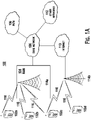
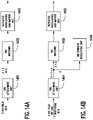
- FIG. 1A is a diagram of an example communications system 100 in which one or more disclosed embodiments may be implemented.
- the communications system 100 may be a multiple access system that provides content, such as voice, data, video, messaging, broadcast, etc., to multiple wireless users.
- the communications system 100 may enable multiple wireless users to access such content through the sharing of system resources, including wireless bandwidth.
- the communications systems 100 may employ one or more channel access methods, such as code division multiple access (CDMA), time division multiple access (TDMA), frequency division multiple access (FDMA), orthogonal FDMA (OFDMA), single-carrier FDMA (SC-FDMA), and the like.
- CDMA code division multiple access
- TDMA time division multiple access
- FDMA frequency division multiple access
- OFDMA orthogonal FDMA
- SC-FDMA single-carrier FDMA
- the communications system 100 may include wireless transmit/receive units (WTRUs) 102a, 102b, 102c, 102d, a radio access network (RAN) 104, a core network 106, a public switched telephone network (PSTN) 108, the Internet 110, and other networks 112, though it will be appreciated that the disclosed embodiments contemplate any number of WTRUs, base stations, networks, and/or network elements.
- WTRUs 102a, 102b, 102c, 102d may be any type of device configured to operate and/or communicate in a wireless environment.
- the WTRUs 102a, 102b, 102c, 102d may be configured to transmit and/or receive wireless signals and may include user equipment (UE), a mobile station, a fixed or mobile subscriber unit, a pager, a cellular telephone, a personal digital assistant (PDA), a smartphone, a laptop, a netbook, a personal computer, a wireless sensor, consumer electronics, and the like.
- UE user equipment
- PDA personal digital assistant
- smartphone a laptop
- netbook a personal computer
- a wireless sensor consumer electronics, and the like.
- the communications systems 100 may also include a base station 114a and a base station 114b.
- Each of the base stations 114a, 114b may be any type of device configured to wirelessly interface with at least one of the WTRUs 102a, 102b, 102c, 102d to facilitate access to one or more communication networks, such as the core network 106, the Internet 110, and/or the networks 112.
- the base stations 114a, 114b may be a base transceiver station (BTS), a Node-B, an eNode B, a Home Node B, a Home eNode B, a site controller, an access point (AP), a wireless router, and the like. While the base stations 114a, 114b are each depicted as a single element, it will be appreciated that the base stations 114a, 114b may include any number of interconnected base stations and/or network elements.
- the base station 114a may be part of the RAN 104, which may also include other base stations and/or network elements (not shown), such as a base station controller (BSC), a radio network controller (RNC), relay nodes, etc.
- BSC base station controller
- RNC radio network controller
- the base station 114a and/or the base station 114b may be configured to transmit and/or receive wireless signals within a particular geographic region, which may be referred to as a cell (not shown).
- the cell may further be divided into cell sectors.
- the cell associated with the base station 114a may be divided into three sectors.
- the base station 114a may include three transceivers, i.e., one for each sector of the cell.
- the base station 114a may employ multiple-input multiple output (MIMO) technology and, therefore, may utilize multiple transceivers for each sector of the cell.
- MIMO multiple-input multiple output
- the base stations 114a, 114b may communicate with one or more of the WTRUs 102a, 102b, 102c, 102d over an air interface 116, which may be any suitable wireless communication link (e.g., radio frequency (RF), microwave, infrared (IR), ultraviolet (UV), visible light, etc.).
- the air interface 116 may be established using any suitable radio access technology (RAT).
- RAT radio access technology
- the communications system 100 may be a multiple access system and may employ one or more channel access schemes, such as CDMA, TDMA, FDMA, OFDMA, SC-FDMA, and the like.
- the base station 114a in the RAN 104 and the WTRUs 102a, 102b, 102c may implement a radio technology such as Universal Mobile Telecommunications System (UMTS) Terrestrial Radio Access (UTRA), which may establish the air interface 116 using wideband CDMA (WCDMA).
- WCDMA may include communication protocols such as High-Speed Packet Access (HSPA) and/or Evolved HSPA (HSPA+).
- HSPA may include High-Speed Downlink Packet Access (HSDPA) and/or High-Speed Uplink Packet Access (HSUPA).
- the base station 114a and the WTRUs 102a, 102b, 102c may implement a radio technology such as Evolved UMTS Terrestrial Radio Access (E-UTRA), which may establish the air interface 116 using Long Term Evolution (LTE) and/or LTE-Advanced (LTE-A).
- E-UTRA Evolved UMTS Terrestrial Radio Access
- LTE Long Term Evolution
- LTE-A LTE-Advanced
- the base station 114a and the WTRUs 102a, 102b, 102c may implement radio technologies such as Institute for Electrical and Electronics Engineers (IEEE) 802.16 (i.e., Worldwide Interoperability for Microwave Access (WiMAX)), CDMA2000, CDMA2000 1X, CDMA2000 EV-DO, Interim Standard 2000 (IS-2000), Interim Standard 95 (IS-95), Interim Standard 856 (IS-856), Global System for Mobile communications (GSM), Enhanced Data rates for GSM Evolution (EDGE), GSM EDGE (GERAN), and the like.
- IEEE Institute for Electrical and Electronics Engineers
- WiMAX Worldwide Interoperability for Microwave Access
- CDMA2000, CDMA2000 1X, CDMA2000 EV-DO Code Division Multiple Access 2000
- IS-95 Interim Standard 95
- IS-856 Interim Standard 856
- GSM Global System for Mobile communications
- GSM Global System for Mobile communications
- EDGE Enhanced Data rates for GSM Evolution
- GERAN GSM ED
- the base station 114b in FIG. 1A may be a wireless router, Home Node B, Home eNode B, or access point, for example, and may utilize any suitable RAT for facilitating wireless connectivity in a localized area, such as a place of business, a home, a vehicle, a campus, and the like.
- the base station 114b and the WTRUs 102c, 102d may implement a radio technology such as IEEE 802.11 to establish a wireless local area network (WLAN).
- the base station 114b and the WTRUs 102c, 102d may implement a radio technology such as IEEE 802.15 to establish a wireless personal area network (WPAN).
- WLAN wireless local area network
- WPAN wireless personal area network
- the base station 114b and the WTRUs 102c, 102d may utilize a cellular-based RAT (e.g., WCDMA, CDMA2000, GSM, LTE, LTE-A, etc.) to establish a picocell or femtocell.
- a cellular-based RAT e.g., WCDMA, CDMA2000, GSM, LTE, LTE-A, etc.
- the base station 114b may have a direct connection to the Internet 110.
- the base station 114b may not be required to access the Internet 110 via the core network 106.
- the RAN 104 may be in communication with the core network 106, which may be any type of network configured to provide voice, data, applications, and/or voice over internet protocol (VoIP) services to one or more of the WTRUs 102a, 102b, 102c, 102d.
- the core network 106 may provide call control, billing services, mobile location-based services, pre-paid calling, Internet connectivity, video distribution, etc., and/or perform high-level security functions, such as user authentication.
- the RAN 104 and/or the core network 106 may be in direct or indirect communication with other RANs that employ the same RAT as the RAN 104 or a different RAT.
- the core network 106 may also be in communication with another RAN (not shown) employing a GSM radio technology.
- the core network 106 may also serve as a gateway for the WTRUs 102a, 102b, 102c, 102d to access the PSTN 108, the Internet 110, and/or other networks 112.
- the PSTN 108 may include circuit-switched telephone networks that provide plain old telephone service (POTS).
- POTS plain old telephone service
- the Internet 110 may include a global system of interconnected computer networks and devices that use common communication protocols, such as the transmission control protocol (TCP), user datagram protocol (UDP) and the internet protocol (IP) in the TCP/IP internet protocol suite.
- the networks 112 may include wired or wireless communications networks owned and/or operated by other service providers.
- the networks 112 may include another core network connected to one or more RANs, which may employ the same RAT as the RAN 104 or a different RAT.
- the WTRUs 102a, 102b, 102c, 102d in the communications system 100 may include multi-mode capabilities, i.e., the WTRUs 102a, 102b, 102c, 102d may include multiple transceivers for communicating with different wireless networks over different wireless links.
- the WTRU 102c shown in FIG. 1A may be configured to communicate with the base station 114a, which may employ a cellular-based radio technology, and with the base station 114b, which may employ an IEEE 802 radio technology.
- FIG. 1B is a system diagram of an example WTRU 102.
- the WTRU 102 may include a processor 118, a transceiver 120, a transmit/receive element 122, a speaker/microphone 124, a keypad 126, a display/touchpad 128, non-removable memory 130, removable memory 132, a power source 134, a global positioning system (GPS) chipset 136, and other peripherals 138.
- GPS global positioning system
- the processor 118 may be a general purpose processor, a special purpose processor, a conventional processor, a digital signal processor (DSP), a plurality of microprocessors, one or more microprocessors in association with a DSP core, a controller, a microcontroller, Application Specific Integrated Circuits (ASICs), Field Programmable Gate Array (FPGAs) circuits, any other type of integrated circuit (IC), a state machine, and the like.
- the processor 118 may perform signal coding, data processing, power control, input/output processing, and/or any other functionality that enables the WTRU 102 to operate in a wireless environment.
- the processor 118 may be coupled to the transceiver 120, which may be coupled to the transmit/receive element 122. While FIG. 1B depicts the processor 118 and the transceiver 120 as separate components, it will be appreciated that the processor 118 and the transceiver 120 may be integrated together in an electronic package or chip.
- the transmit/receive element 122 may be configured to transmit signals to, or receive signals from, a base station (e.g., the base station 114a) over the air interface 116.
- a base station e.g., the base station 114a
- the transmit/receive element 122 may be an antenna configured to transmit and/or receive RF signals.
- the transmit/receive element 122 may be an emitter/detector configured to transmit and/or receive IR, UV, or visible light signals, for example.
- the transmit/receive element 122 may be configured to transmit and receive both RF and light signals. It will be appreciated that the transmit/receive element 122 may be configured to transmit and/or receive any combination of wireless signals.
- the WTRU 102 may include any number of transmit/receive elements 122. More specifically, the WTRU 102 may employ MIMO technology. Thus, in one embodiment, the WTRU 102 may include two or more transmit/receive elements 122 (e.g., multiple antennas) for transmitting and receiving wireless signals over the air interface 116.
- the transceiver 120 may be configured to modulate the signals that are to be transmitted by the transmit/receive element 122 and to demodulate the signals that are received by the transmit/receive element 122.
- the WTRU 102 may have multi-mode capabilities.
- the transceiver 120 may include multiple transceivers for enabling the WTRU 102 to communicate via multiple RATs, such as UTRA and IEEE 802.11, for example.
- the processor 118 of the WTRU 102 may be coupled to, and may receive user input data from, the speaker/microphone 124, the keypad 126, and/or the display/touchpad 128 (e.g., a liquid crystal display (LCD) display unit or organic light-emitting diode (OLED) display unit).
- the processor 118 may also output user data to the speaker/microphone 124, the keypad 126, and/or the display/touchpad 128.
- the processor 118 may access information from, and store data in, any type of suitable memory, such as the non-removable memory 130 and/or the removable memory 132.
- the non-removable memory 130 may include random-access memory (RAM), read-only memory (ROM), a hard disk, or any other type of memory storage device.
- the removable memory 132 may include a subscriber identity module (SIM) card, a memory stick, a secure digital (SD) memory card, and the like.
- SIM subscriber identity module
- SD secure digital
- the processor 118 may access information from, and store data in, memory that is not physically located on the WTRU 102, such as on a server or a home computer (not shown).
- the processor 118 may receive power from the power source 134, and may be configured to distribute and/or control the power to the other components in the WTRU 102.
- the power source 134 may be any suitable device for powering the WTRU 102.
- the power source 134 may include one or more dry cell batteries (e.g., nickel-cadmium (NiCd), nickel-zinc (NiZn), nickel metal hydride (NiMH), lithium-ion (Li-ion), etc.), solar cells, fuel cells, and the like.
- the processor 118 may also be coupled to the GPS chipset 136, which may be configured to provide location information (e.g., longitude and latitude) regarding the current location of the WTRU 102.
- location information e.g., longitude and latitude
- the WTRU 102 may receive location information over the air interface 116 from a base station (e.g., base stations 114a, 114b) and/or determine its location based on the timing of the signals being received from two or more nearby base stations. It will be appreciated that the WTRU 102 may acquire location information by way of any suitable location-determination method while remaining consistent with an embodiment.
- the processor 118 may further be coupled to other peripherals 138, which may include one or more software and/or hardware modules that provide additional features, functionality and/or wired or wireless connectivity.
- the peripherals 138 may include an accelerometer, an e-compass, a satellite transceiver, a digital camera (for photographs or video), a universal serial bus (USB) port, a vibration device, a television transceiver, a hands free headset, a Bluetooth ® module, a frequency modulated (FM) radio unit, a digital music player, a media player, a video game player module, an Internet browser, and the like.
- the peripherals 138 may include an accelerometer, an e-compass, a satellite transceiver, a digital camera (for photographs or video), a universal serial bus (USB) port, a vibration device, a television transceiver, a hands free headset, a Bluetooth ® module, a frequency modulated (FM) radio unit, a digital music player, a media player, a video
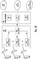
- FIG. 1C is a system diagram of the RAN 104 and the core network 106.
- the RAN 104 may be an access service network (ASN) that employs IEEE 802.16 radio technology to communicate with the WTRUs 102a, 102b, 102c over the air interface 116.
- ASN access service network
- the communication links between the different functional entities of the WTRUs 102a, 102b, 102c, the RAN 104, and the core network 106 may be defined as reference points.
- the RAN 104 may include base stations 140a, 140b, 140c, and an ASN gateway 142, though it will be appreciated that the RAN 104 may include any number of base stations and ASN gateways while remaining consistent with an embodiment.
- the base stations 140a, 140b, 140c may each be associated with a particular cell (not shown) in the RAN 104 and may each include one or more transceivers for communicating with the WTRUs 102a, 102b, 102c over the air interface 116.
- the base stations 140a, 140b, 140c may implement MIMO technology.
- the base station 140a for example, may use multiple antennas to transmit wireless signals to, and receive wireless signals from, the WTRU 102a.
- the base stations 140a, 140b, 140c may also provide mobility management functions, such as handoff triggering, tunnel establishment, radio resource management, traffic classification, quality of service (QoS) policy enforcement, and the like.
- the ASN gateway 142 may serve as a traffic aggregation point and may be responsible for paging, caching of subscriber profiles, routing to the core network 106, and the like.
- the air interface 116 between the WTRUs 102a, 102b, 102c and the RAN 104 may be defined as an R1 reference point that implements the IEEE 802.16 specification.
- each of the WTRUs 102a, 102b, 102c may establish a logical interface (not shown) with the core network 106.
- the logical interface between the WTRUs 102a, 102b, 102c and the core network 106 may be defined as an R2 reference point, which may be used for authentication, authorization, IP host configuration management, and/or mobility management.
- the communication link between each of the base stations 140a, 140b, 140c may be defined as an R8 reference point that includes protocols for facilitating WTRU handovers and the transfer of data between base stations.
- the communication link between the base stations 140a, 140b, 140c and the ASN gateway 215 may be defined as an R6 reference point.
- the R6 reference point may include protocols for facilitating mobility management based on mobility events associated with each of the WTRUs 102a, 102b, 102c.
- the RAN 104 may be connected to the core network 106.
- the communication link between the RAN 104 and the core network 106 may defined as an R3 reference point that includes protocols for facilitating data transfer and mobility management capabilities, for example.
- the core network 106 may include a mobile IP home agent (MIP-HA) 144, an authentication, authorization, accounting (AAA) server 146, and a gateway 148. While each of the foregoing elements are depicted as part of the core network 106, it will be appreciated that any one of these elements may be owned and/or operated by an entity other than the core network operator.
- MIP-HA mobile IP home agent
- AAA authentication, authorization, accounting
- the MIP-HA may be responsible for IP address management, and may enable the WTRUs 102a, 102b, 102c to roam between different ASNs and/or different core networks.
- the MIP-HA 144 may provide the WTRUs 102a, 102b, 102c with access to packet-switched networks, such as the Internet 110, to facilitate communications between the WTRUs 102a, 102b, 102c and IP-enabled devices.
- the AAA server 146 may be responsible for user authentication and for supporting user services.
- the gateway 148 may facilitate interworking with other networks.
- the gateway 148 may provide the WTRUs 102a, 102b, 102c with access to circuit-switched networks, such as the PSTN 108, to facilitate communications between the WTRUs 102a, 102b, 102c and traditional land-line communications devices.
- the gateway 148 may provide the WTRUs 102a, 102b, 102c with access to the networks 112, which may include other wired or wireless networks that are owned and/or operated by other service providers.
- the RAN 104 may be connected to other ASNs and the core network 106 may be connected to other core networks.
- the communication link between the RAN 104 the other ASNs may be defined as an R4 reference point, which may include protocols for coordinating the mobility of the WTRUs 102a, 102b, 102c between the RAN 104 and the other ASNs.
- the communication link between the core network 106 and the other core networks may be defined as an R5 reference, which may include protocols for facilitating interworking between home core networks and visited core networks.
- the term transmitter may mean a WTRU, a station (STA), a base station, a node B, or an access point (AP), among others.
- the term receiver may mean a WTRU, an STA, a base station, a node B, or an AP, among others.
- the transmitter or the receiver may communicate using any communications protocol including, but not limited to, an Institute for Electrical and Electronics Engineers (IEEE) 802 communications protocol, such as 802.11n, 802.11ac, 802.11af, or 802.11ah, among others.
- the transmitter or the receiver may also operate in any spectrum including, but not limited to, a television (TV) whitespace spectrum or a sub-1 gigahertz (GHz) spectrum.
- TV television
- GHz sub-1 gigahertz
- Preambles are widely used in communications systems.
- a preamble may be transmitted stand-alone, (i.e., without a subsequent data transmission), or may be a header for a data transmission.
- the preamble allows for training a receiver to obtain information about channel conditions between a transmitter and the receiver, and thereby improved reception of subsequent data transmissions (for example, user data) is facilitated.
- a preamble may be used for sending control information to the receiver that may be necessary for reception of subsequent data transmissions.
- FIG. 2 shows a preamble for a data transmission.
- the preamble 201 is transmitted prior to a data transmission 202.
- the preamble 201 may include training symbols that may be used for automatic gain control (AGC), timing and frequency acquisition, or channel estimation by the receiver. Furthermore, the training symbols may be used for frequency or time synchronization between the transmitter and the receiver.
- AGC automatic gain control
- the training symbols may be used for frequency or time synchronization between the transmitter and the receiver.
- the preamble may include dedicated bits that carry control information to the receiver.
- the dedicated bits may indicate to the receiver a transmission bandwidth, modulation or coding information, beamforming information, or space-time coding information.
- a communications protocol may define a preamble for use in the communications protocol.
- a communications protocol may define the training symbols of the preamble and the meaning of the dedicated bits of the preamble.
- the transmission protocol may define the length of the preamble (in bits, bytes, or symbols), the time or frequency resources used for transmission of the preamble, the encoding or modulation of the preamble, or the interpretation of the dedicated bits of the preamble.
- a transmitter or a receiver that is compliant with the communications protocol is aware of the manner in which the preamble is defined and may, therefore, successfully interpret and utilize the preamble.
- preambles may also be updated according to the requirements of the communications protocols.
- transmitters and receivers using the communications protocols are required to be updated in order to be compliant with the latest communications protocols and in order to receive and properly process preambles of the communications protocols.
- a mixed format preamble may be used to allow legacy transmitters and receivers to communicate using the updated communications protocols.
- the mixed format preamble has both a legacy portion for use by legacy transmitters and receivers and a non-legacy portion for use by non-legacy transmitters and receivers.
- the non-legacy portion of the preamble is referred to herein as a very high throughput (VHT) portion.
- VHT very high throughput
- a transmitter or a receiver that is compliant with the updated communications protocols is referred to herein as a VHT transmitter or a VHT receiver or a non-legacy transmitter or a non-legacy receiver.
- FIG. 3A shows a mixed format preamble 300.
- the mixed format preamble 300 comprises a legacy portion 311 and a VHT portion 312.
- the legacy portion 311 of the mixed format preamble 300 may comprise training fields and control information fields for use by legacy receivers.
- Legacy receivers may process the legacy portion 311 of the mixed format preamble 300 and may subsequently be able to interpret the VHT portion 312 using information provided in the legacy portion 311.
- the VHT portion 312 of the mixed format preamble 300 may comprise training fields and control information fields for use by non-legacy receivers or VHT receivers.
- Non-legacy receivers or VHT receivers may ignore or skip the legacy portion 311 and only use the VHT portion 312 of the mixed format preamble 300.
- FIG. 3B shows an example of a mixed format preamble.
- the mixed format preamble 300 comprises a legacy portion 311 and a VHT portion 312.
- the legacy portion 311 comprises a legacy short training field (STF), referred to herein as L-STF 321, a legacy long training field (LTF), referred to herein as L-LTF 322, and a legacy signal (SIG) field, referred to herein as L-SIG 323.
- STF legacy short training field
- L-LTF legacy long training field
- SIG legacy signal
- the VHT portion 312 comprises a first VHT SIG field, referred to herein as VHT-SIG-A 324, and a second VHT SIG field, referred to herein as VHT-SIG-B 327, an STF, referred to herein as VHT-STF 325, and one or more LTFs, referred to herein as VHT-LTFs 326 1-N and collectively referred to hereinafter as VHT-LTFs 326.
- L-STF 321 comprises one or more short training symbols and may be used for AGC and timing and frequency acquisition by a legacy receiver.
- L-LTF 322 comprises one or more long training symbols and may be used for channel estimation by a receiver.
- L-SIG 323 may include dedicated bits that signal to a receiver control information, such as bandwidth information, modulation or coding information, and the like.
- Legacy receivers may train for reception of subsequent data transmission based on L-STF 321 and L-LTF 322. Further, legacy receivers may receive control information included in L-SIG 323.
- VHT-STF 325 comprises one or more short training symbols and may be used for AGC and timing and frequency acquisition by a non-legacy or a VHT receiver.
- VHT-LTFs 326 comprise one or more long training symbols and may be used for antenna calibration by a non-legacy receiver.
- VHT-SIG-A 324 and VHT-SIG-B 327 include control information intended for a non-legacy receiver.
- Non-legacy receivers may train using the training symbols of VHT-STF 325 and VHT-LTFs 326.
- the non-legacy receivers may also receive control information included in VHT-SIG-A 324 and VHT-SIG-B 327. Further, non-legacy receivers may perform AGC and time and frequency acquisition based on VHT-STF 325, and antenna calibration and the like based on VHT-LTFs 326.
- VHT-SIG-A 324 of the VHT portion 312 of the mixed format preamble 300 may include information intended for multiple non-legacy receivers
- VHT-SIG-B 327 of the VHT portion 312 of the mixed format preamble 300 may include information intended for one non-legacy receiver.
- the multiple non-legacy receivers may acquire control information intended for the multiple non-legacy receivers from VHT-SIG-A 324, such as a group identity (ID).
- one non-legacy receiver may acquire information intended to the non-legacy receiver such as modulation and coding scheme (MCS) from VHT-SIG-B 327.
- MCS modulation and coding scheme
- the VHT portion 312 of the mixed format preamble 300 may include an Omni portion intended for multiple non-legacy receivers and a multi-user (MU) portion intended for one non-legacy receiver.
- MU multi-user
- a mixed format preamble 300 is associated with an increased signaling overhead due to the inclusion of the legacy portion 311.
- An alternative to the signaling overhead of the mixed format preamble 300 is a Greenfield preamble.
- a Greenfield preamble does not include a legacy portion and instead includes only a VHT portion for use by non-legacy receivers or VHT receivers. Because the Greenfield preamble does not include a legacy portion, additional resources may be allocated to the Greenfield preamble. The additional resources allocated to the Greenfield preamble result in improved channel estimation and time and frequency acquisition, among other benefits.
- the Greenfield preamble may include STFs and LTFs having longer training symbols than a mixed format preamble without adding additional overhead. Further, the STFs and LTFs of the Greenfield preamble may have longer guard intervals than a counterpart mixed format preamble.
- FIG. 4A shows a Greenfield preamble.
- the Greenfield preamble 400 comprises a Greenfield (GF) STF (GF-STF) 401, a first GF LTF, referred to herein as GF-LTF1 402, and additional GF LTFs, referred to herein as GF-LTFs 404 1-N and collectively referred to hereinafter as GF-LTFs 404, and singularly referred to hereinafter as GF-LTF 404 i .
- GF-LTFs 404 may be data or expansion LTFs.
- the Greenfield preamble 400 also comprises a first SIG field, referred to herein GF-SIG-A 403, and a second SIG field, referred to herein as GF-SIG-B 405.
- GF-STF 401, GF-LTF1 402, and GF-SIG-A 403 may be intended for multiple non-legacy receivers, and thus may form an Omni portion of the Greenfield preamble 400.
- GF-LTFs 404 and GF-SIG-B 405 may be intended for one or more specific non-legacy receivers, and thus may form an MU portion of the Greenfield preamble 400.
- GF-STF 401 may comprise one or more short training symbols and may be used for AGC and timing and frequency acquisition by a non-legacy receiver, and a non-legacy receiver may perform AGC and timing and frequency acquisition based on GF-STF 401.
- GF-LTF1 402 may comprise one or more long training symbols and may be used for channel estimation by a non-legacy receiver, and a non-legacy receiver may perform channel estimation based on GF-LTF1 402.
- GF-SIG-A 403 may include dedicated bits that signal control information to multiple non-legacy receivers.
- the multiple non-legacy receivers may receive the control information, such as group ID, from GF-SIG-A 403. Further, GF-SIG-A 403 may provide an indication as to whether the Greenfield preamble 400 is an MU preamble or an SU preamble.
- a non-legacy receiver may know whether to receive or process GF-SIG-B 405 of the MU portion of the Greenfield preamble 400 based on the indication in GF-SIG-A 403.
- GF-SIG-B 405 includes information intended for a subset of one or more specific non-legacy receivers of the multiple receivers, such as modulation and coding scheme (MCS) information of subsequent data transmissions.
- MCS modulation and coding scheme
- GF-LTFs 404 comprise long training symbols and may be used for additional training of a non-legacy receiver, such as antenna calibration.
- GF-STF 401 may be constructed from an orthogonal frequency division multiplexing (OFDM) sequence denoted as S -x,x , where 2x+1 represents the number of OFDM subcarriers. Because the Greenfield preamble 400 does not include a legacy portion, additional resources for a longer OFDM sequence may be allocated to the GF-STF 401 of the Greenfield preamble 400 than used in L-STF 321 or VHT-STF 325 of the mixed format preamble 300.
- OFDM orthogonal frequency division multiplexing
- a longer S -x,x may be used in a 40MHz bandwidth.
- a time domain waveform having a 0.8 microseconds ( ⁇ s) period may be obtained from the sequence S -x,x by applying an inverse fast Fourier transform (IFFT) and adding a cyclic prefix.
- the time domain waveform may be repeated ten times to form a GF-STF 401 with a duration of 8 ⁇ s. It is noted that a GF-STF 401 with a duration of 16 ⁇ s may be obtained by utilizing half-clocking and a GF-STF 401 with a 32 ⁇ s duration may be obtained by utilizing quarter-clocking.
- Table 1 shows a tone scaling factor and duration of GF-STF 401 for various bandwidths. It is noted that the tone scaling factor and GF-STF 401 duration may be similarly obtained for any other bandwidth, such as 1, 2, 4, or 8MHz. Table 1: Tone scaling factor and duration of GF-STF for various bandwidths. Bandwidth (MHz) 5 10 20 40 80 160 Tone scaling factor 12 12 12 24 48 96 GF-STF duration (32 ⁇ s) 32 16 8 8 8 8 8 8 8
- GF-LTF1 402 of the Greenfield preamble 400 of FIG. 4 may be 8 ⁇ s in duration, as compared with a GF-LTF 404 i of 4 ⁇ s in duration. Further, GF-LTF1 402 may comprise two periods of long training symbols preceded by a double length 1.6 ⁇ s cyclic prefix. The usage of two periods of long training symbols and a double length cyclic prefix is facilitated by the fact that the Greenfield preamble 400 does not include a legacy portion, as compared to a mixed format preamble 300 and, therefore, more resources may be allocated to the Greenfield preamble 400 without incurring overhead.
- Table 2 shows a tone scaling factor, GF-LTF1 duration, and guard interval (GI) time for various bandwidths. It is noted that the tone scaling factor, GF-LTF1 duration, and GI time may be similarly obtained for any other bandwidth, such as 1, 2, 4, 8, or 16MHz. Table 2: Tone scaling factor, GF-LTF1 duration, and GI time for various bandwidths. Bandwidth (MHz) 5 10 20 40 80 160 Tone scaling factor 56 56 56 56 114 242 484 GF-LTF1 Duration (32 ⁇ s) 32 16 8 8 8 8 GI time 6.4 3.2 1.6 1.6 1.6 1.6
- training symbols for GF-LTF1 402 may be half-clocked for 5MHz operation and quarter-clocked for 10MHz operation.
- a preamble may include information intended for multiple receivers, whereby the preamble is said to include a multi-user (MU) portion or the preamble is said to be an MU preamble.
- a preamble may be intended for a single receiver, whereby the preamble is said to be an SU preamble.
- the Greenfield preamble 400 may be used as the basis for an SU preamble, as described with reference to FIG. 4B .
- FIG. 4B shows an SU preamble in accordance with the Greenfield preamble.
- the SU preamble 410 comprises STF 411, a first LTF, denoted LTF1 412, a signal (SIG) 413 field, and one or more additional LTFs, denoted as LTF2 414 1 , ..., LTFN 414 N-1 and referred to collectively hereinafter as LTFs 414.
- STF 411 of the SU preamble 410 may be the same as GF-STF 401 of the Greenfield preamble 400.
- LTF1 412 may be the same as GF-LTF1 402
- SIG 413 may be the same as GF-SIG-A 403
- LTFs 414 may be the same as GF-LTFs 404 of the Greenfield preamble 400. It is noted that because an SU preamble only needs to signal control information to a single receiver, the signaling of control information may consolidated in SIG 413 and, thus, there is no need for an additional MU SIG field, such as GF-SIG-B 405 of the Greenfield preamble 400.
- Greenfield preamble 400 may also be used as the basis for an MU preamble, as described with reference to FIG. 4C .
- an MU preamble may include a first portion intended for multiple receivers, referred to herein as an Omni portion, and a second portion intended for a subset of the multiple receivers, referred to herein as an MU portion.
- FIG. 4C shows an MU preamble in accordance with the Greenfield preamble.
- the MU preamble 420 comprises an Omni portion 421 and an MU portion 425.
- the Omni portion 421 comprises an STF 422, a first LTF, referred to herein as LTF1 423, and a first SIG field, referred to herein as SIG-A 424.
- STF 422 may be the same as GF-STF 401 of the Greenfield preamble 400
- LTF1 423 may be the same as GF-LTF1 402 of the Greenfield preamble 400
- SIG-A 424 may be the same as GF-SIG-A 403 of the Greenfield preamble 400.
- the Omni portion 421 of the MU preamble 420 is intended for multiple receivers and the multiple receivers may receive and utilize the Omni portion 421 of the MU preamble 420 as described herein.
- the multiple receivers may perform AGC and timing and frequency acquisition based on STF 422 of the Omni portion 421, and channel estimation based on LTF1 423 of the Omni portion 421.
- the multiple receivers may acquire control information intended for the multiple receivers, such as a group identity (ID), from SIG-A 424 of the Omni portion 421 of the MU preamble 420.
- ID group identity
- the MU portion 425 of the MU preamble 420 comprises an additional STF, referred to herein as MU-STF 426, one or more additional LTFs, denoted as LTF2 427 1 , ..., LTFN 427 N-1 and referred to collectively herein as LTFs 427, and a second SIG field, referred to herein as SIG-B 428.
- LTFs 427 of the MU portion may be the same as GF-LTFs 404 of the Greenfield preamble 400, and SIG-B 428 may also be the same as GF-SIG-B 405 of the Greenfield preamble 400.
- MU-STF 426 may alternatively be included in the MU preamble 420.
- MU-STF 426 may comprise short training symbols and may be used for performing finer AGC, and time and frequency acquisition than performed based on STF 422 of the Omni portion 421.
- Greenfield preamble 400 may be used by non-legacy receivers or VHT receivers. Further, a mixed format preamble 300 may be used by both VHT receivers and legacy receivers.
- FIG. 5 shows a method for preamble transmission.
- a transmitter determines whether to transmit a Greenfield preamble 400 or a mixed format preamble 300 501. If the transmitter determines that a Greenfield preamble 400 is to be transmitted, then the transmitter transmits the Greenfield preamble 400 comprising GF-STF 401, GF-LTF1 402, GF-SIG-A 403, GF-LTFs 404, and GF-SIG-B 405 502. If the transmitter determines that a mixed format preamble 300 is to be transmitted, then the transmitter transmits the legacy portion 311 of the mixed format preamble 300 comprising L-STF 321, L-LTF 322, and L-SIG 323 503. The transmitter also transmits the VHT portion 312 of the mixed format preamble 300 comprising VHT-SIG-A 324, VHT-STF 325, VHT-LTFs 326, and VHT-SIG-B 327 504.
- a receiver may be either a VHT receiver that is capable of processing both a VHT preamble and a mixed format preamble or a legacy receiver that is capable of processing only a mixed format preamble.
- FIG. 6 shows a method for processing a preamble.
- a receiver receives a preamble 601.
- the receiver determines the type of SIG field of the preamble 602. If the receiver determines that the SIG field is a GF-SIG-A 403, then the receiver processes the GF-SIG-A 403 603. The receiver also processes GF-SIG-B 405 604. If, on the other hand, the receiver determines that the SIG field is an L-SIG 323, the receiver processes the L-SIG 323 605.
- a preamble may mean any preamble, such as mixed format preamble 300, Greenfield preamble 400, SU preamble 410, or MU preamble 420.
- an STF may mean any STF of any preamble, such as L-STF 321 or VHT-STF 325 of mixed format preamble 300, GF-STF 401 of Greenfield preamble 400, STF 411 of SU preamble 410, or STF 422 or MU-STF 426 of MU preamble 420.
- an LTF may mean any LTF of any preamble, such as L-LTF 322 of mixed format preamble 300, or GF-LTF1 402 of Greenfield preamble 400, LTF1 412 of SU preamble 410, or LTF1 423 of MU preamble 420.
- a SIG field may mean any SIG field of a preamble, such as L-SIG 323, VHT-SIG-A 324, or VHT-SIG-B 327 of mixed format preamble 300, GF-SIG-A 403 or GF-SIG-B 405 of Greenfield preamble 400, SIG 413 field of SU preamble 410, or SIG-A 424 or SIG-B 428 of MU preamble 420.
- a receiver may mean a legacy receiver, or a non-legacy or VHT receiver.
- a preamble may include an indication as to whether the preamble is an SU preamble intended for a specific receiver or an MU preamble intended for multiple receivers.
- the SIG field may include one or more bits or a field to indicate whether the preamble is an SU preamble or an MU preamble, and a receiver may determine from the SIG field whether the preamble is an SU preamble or an MU preamble. If the receiver determines that the preamble is an MU preamble, the receiver may obtain control information (for example, group ID or N STS ) related to multiple receivers from the SIG field. Further, the receiver may obtain information specific to the receiver (for example, MCS) from a SIG field of an MU portion of the preamble.
- control information for example, group ID or N STS
- the receiver may obtain control information (for example, MCS or N STS ) specific to the receiver from the SIG field.
- control information for example, MCS or N STS
- an STF or an LTF of a preamble may be used to indicate whether the preamble is an SU preamble or an MU preamble.
- a sequence or subcarrier mapping of the STF or LTF may be used to indicate whether the preamble is an SU preamble or an MU preamble.
- a receiver may be aware of a first STF sequence or subcarrier mapping used to indicate an SU preamble and a second STF sequence or subcarrier mapping used to indicate an MU preamble.
- a receiver may receive an STF and may apply frequency domain correlation to the received STF and the first STF sequence, and may also apply frequency domain correlation to the received STF and the second STF sequence, in order to determine whether the preamble is an SU preamble or an MU preamble.
- a receiver may determine whether the preamble is an SU preamble or an MU preamble based on an LTF.
- cyclic redundancy check (CRC) masking of a SIG field may be performed to indicate whether the preamble is an SU preamble or an MU preamble.
- error protection for a SIG field may be provided through a CRC having a length of L bits and denoted as C L- 1 , C L -2 ,..., C 0 .
- the CRC may be masked with a sequence x L -1 , x L -2 ,..., x 0 to indicate whether the preamble is an SU preamble or an MU preamble.
- CRC masking may be performed by applying a modulo 2 operation to the respective bit positions of the CRC and the sequence.
- a receiver may receive the preamble and calculate L CRC bits based on the SIG field. The receiver may further determine whether the preamble is an SU preamble or an MU preamble by comparing the received CRC bits with the calculated CRC bits. It is noted that the masked CRC may be included in the SIG field or elsewhere in the preamble (for example, in a SERVICE field in IEEE 802.11 communications).
- a CRC mask may only be associated with a particular transmission mode and the presence of the CRC mask may indicate the transmission mode.
- a CRC mask may only be associated with a 1MHZ transmission mode.
- tail bits that terminate a convolutional code for a SIG field may be used to indicate whether a preamble is an MU preamble or an SU preamble.
- the SIG field may be terminated with the tail bits [0 0 0 0 0 0] to indicate that the preamble is an SU preamble, or the SIG field may be terminated with the tail bits [1 1 1 1 1] to indicate that the preamble is an MU preamble.
- tail bits may carry additional information bits.
- two bits of information may be carried by choosing among four different termination sequences (e.g., termination sequences [0 0 0 0 0 0], [1 1 1 0 0 0], [0 0 0 1 1] or [1 1 1 1 1]).
- the termination sequences may be chosen to maximize a Hamming distance between resultant codewords. It is noted that three bits may indicate eight possible termination states, whereas four bits may indicate 16 possible termination states up to a maximum of 6 bits, which may be equivalent to a code that is not terminated.
- a receiver may perform convolutional decoding to decode the SIG field. Further, the convolutional decoding may be performed assuming that the tail bits are either [0 0 0 0 0 0] or [1 1 1 1 1 1]. After convolutional decoding is performed, a receiver may utilize a maximum likelihood function to determine whether the tail bits of the SIG field are [0 0 0 0 0 0] or [1 1 1 1 1], and thus determine whether the preamble is an MU preamble or an SU preamble. Similarly, when more than one bit of information is indicated using the tail bits, a decoding process may choose the best state to trace back from given possible alternatives.
- a convolution decoder may choose the best metric from the four states of [0 0 0 0 0 0], [1 1 1 0 0 0], [0 0 0 1 1 1], and [1 1 1 1 1] in order to perform tracing back. It is noted that if tail biting is utilized in an encoder, an appropriate tail-biting decoder may be required to be used in a decoder.
- the SIG field of a preamble may include an indication of an operating bandwidth or a mode of operation for preamble transmission or data transmission.
- the SIG field may indicate whether a 1MHz bandwidth or a 2MHz bandwidth or mode of operation is used.
- a bit in the SIG field may be used to indicate the operating bandwidth or the mode of operation.
- a receiver that is capable of operating in either a first bandwidth or a second bandwidth may determine the bandwidth based on the SIG field and the receiver may appropriately process a remainder of the preamble and subsequent data transmissions based on the determined bandwidth (i.e., the receiver may perform detection, or frequency and time synchronization, among others). For example, in IEEE 802.11 communications, if the SIG field indicates 1 MHz bandwidth on either or both an upper or lower 1 MHz band, a receiver may process a preamble or a data transmission according to the 1 MHz bandwidth on either or both of the upper or the lower 1 MHz bands.
- subcarrier demapping may be performed according to a 1 MHz location of received preamble or data and the receiver may set a Network Allocation Vector (NAV) for either or both of the upper or the lower 1 MHz bands and may ignore a packet based on configurations.
- NAV Network Allocation Vector
- a receiver that is only capable of operating in the first bandwidth may determine that the second bandwidth is used and may operate accordingly. For example, the receiver may cease receiving on the second bandwidth in order to conserve battery life.
- the SIG field of a preamble may include an indication of whether packet aggregation is performed. Packet aggregation may be utilized for reducing signaling overhead when available bandwidths are relatively small. Further, packet aggregation results in gain when a large number of receivers or transmitters are available.
- the SIG field may include an indication that a preamble or a data transmission is aggregated, an indication that an aggregated preamble or an aggregated data transmission is intended for one or more specific receivers or multiple receivers, or information for processing or de-aggregation of data transmissions, such as an order of receivers or timing information.
- Aggregation may be performed over contiguous or non-contiguous bandwidths. Further, the contiguous or non-contiguous bandwidths may have the same or different bandwidths. For example, any 5, 10, 40, or 80 MHz bandwidth may be aggregated with any other 5, 10, 40, or 80 MHz bandwidth.
- the SIG field of a preamble may indicate MCS information for a subchannel (i.e., on a subchannel basis).
- the MCS information may include the modulation or coding utilized for each subchannel within a transmission bandwidth.
- the MCS information may indicate a modulation, a coding rate, or a binary convolutional code (BCC) or a low density parity check (LDPC) coding indicator.
- BCC binary convolutional code
- LDPC low density parity check
- a receiver may receive MCS information for each subchannel and may demodulate or decode a transmission over each subchannel based on the MCS information.
- subchannels in a transmission bandwidth or channel width may be non-contiguous or contiguous. Further, multiple contiguous or non-contiguous subchannels may be used simultaneously for wide-bandwidth transmission or multichannel transmission. Further, each of the subchannels may have its own MCS that is indicated using the SIG field.
- a subchannel may have a width of less than 8MHz.
- Channel conditions, such as interference, of a first subchannel may be different than the channel conditions of a second subchannel.
- the difference between the channel conditions of the first subchannel and the second subchannel is expected to be larger than when the first subchannel and the second subchannel are contiguous.
- a subchannel-specific MCS may take into account signal-to-noise ratio (SNR) or bit error rate (BER) conditions for the subchannel or other subchannels.
- SNR signal-to-noise ratio
- BER bit error rate
- the SIG of an Omni portion of a preamble may include MCS information on a subchannel basis that is intended for multiple users (for example, a BCC or LDPC coding indicator for multiple users).
- the SIG field of an MU portion of the preamble may include MCS information on a subchannel basis intended for a subset of users (for example, a modulation and coding rate for a specific user).
- a SIG field of a preamble may include an indication of transmit power control information. Further, a receiver may adjust its transmission power according to the power control information included in the SIG field.
- the SIG field may indicate a power up command indicating that a transmission power should be increased, a power down command indicating that a transmission power should be decreased, or an absolute power level indicating that a transmission power of the receiver should be adjusted to match the absolute power level.
- a SIG field of an Omni portion of a preamble may include a reference transmission power level intended for multiple receivers
- a SIG field of an MU portion of a preamble (for example, SIG-B 428 of MU preamble 420 or GF-SIG-B 405 of Greenfield preamble 400) may include an offset transmission power level relative to the reference transmission power level.
- the offset transmission power level may be intended for one or more specific receivers of the MU portion of the preamble and the specific receiver may adjust its transmission power level to match a power level that is the aggregate of both the reference transmission power level and the offset transmission power level.
- Transmit power control information may include a quantized representation of an absolute power level, a quantized representation of power up or power down indication, a power difference between two measurement intervals for a specific receiver, a power difference between two receivers, or a power difference between a transmitter and a receiver.
- a midamble or a postamble may be utilized in a transmission as described with reference to FIG. 7 .
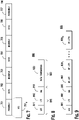
- FIG. 7 shows a transmission including a preamble, midamble, and a postamble.
- the transmission 700 comprises a preamble 701, where the preamble 701 includes a SIG field 701 A , as described herein.
- the transmission also includes data fields 702, 704, 706 which may include any data that is intended for a receiver, a first midamble 703, a second midamble 705 (collectively referred to herein as midambles 703, 705), and a postamble 707.
- the midambles 703, 705 are placed amidst data fields 702, 704, 706 and may comprise STFs or LTFs that may be used by the receiver for time and frequency acquisition, channel estimation, and the like.
- the midambles 703, 705 may be necessary when the aggregate of the length of data fields 702, 704, 706 is large and the time and frequency acquisition and channel estimation acquired by the receiver based on the preamble 701 have become stale or non-applicable to current communications conditions.
- the preamble 701 and the midambles 703, 705 may each use different or orthogonal subcarriers. Further, if available subcarriers are limited, the preamble 701 or the midambles 703, 705 may re-use the subcarriers. Additionally, the preamble 701 and the midambles 703, 705 may be transmitted on different antennas or on orthogonal antennas, or using a spatially orthogonal covering code. Further, each data field 702, 704, 706 may have an MCS associated with the data field 702, 704, 706 and the MCSs may be the same or different for the data fields 702, 704, 706.
- the SIG field 701 A of the preamble 701 includes an indication of the presence of or a location of a midamble (for example, first midamble 703 or second midamble 705) or the postamble 707 in a transmission 700.
- the location may be indicated by a symbol offset to the midamble, a number of symbols between the midambles 703, 705, time between midambles 703, 705, or an index to a pre-determined midamble location (for example, every nth OFDM symbol).
- the indication of a location of the midamble may be determined based on an antenna index or an antenna number.
- the SIG field 701 A of the preamble 701 may also include an indication of a format of the midamble, an index to a format of each midamble, or an index to the format of all preambles.
- the SIG field 701 A of the preamble 701 may also include an indication of a subcarrier pattern of a midamble. Alternatively, a subcarrier pattern may be implicitly indicated using a location of the midamble.
- midambles 703, 705 may each have a subsequently transmitted midamble SIG (MSIG) field.
- MSIG midamble SIG
- Each MSIG field of the midambles 703, 705 may indicate the length of subsequent data fields 704, 706, respectively.
- the length of data field 702 may be indicated by the SIG field 701 A of the preamble 701.
- SIG field 701 A or an MSIG field associated with midambles 703, 705 may indicate the MCS associated with data fields 702, 704, 706.
- a receiver may interpolate channel estimates obtained based on preamble 701, midambles 703, 705, or postamble 707, and may utilize the interpolated channel estimates to process data fields 702, 704, 706. For example, a receiver may interpolate channel estimates obtained based on midambles 703, 705 and utilize the interpolated channel estimates to process data field 704 that is received between the midambles 703, 705. The interpolation may allow for more robust channel estimation.
- a receiver may obtain a Doppler estimate of a channel based on preamble 701, midambles 703, 705, or postamble 707.
- the receiver may also request increasing or decreasing the number of midambles based on the Doppler estimate.
- the Doppler estimate may be sent to a transmitter and may be used to determine whether to increase or decrease the number of midambles sent to the receiver.
- Doppler estimates may also be used for formation of a group of receivers, whereby the group of receivers may have requested the same number of midambles.
- the SIG field of a preamble may indicate usage of a short guard interval (GI) for a subsequent data transmission.
- the SIG field may indicate usage of a short GI using a bit indicator.
- short GI usage may be indicated using a polarity of the pilot tone values of the SIG field. For example, where a SIG field has four pilot tones, pilot tone values [111 -1] may indicate the absence of a short GI, whereas pilot tone values [-1 -1 -1 1] may indicate the presence of a short GI.
- a receiver may process the SIG field and may determine the pilot tone values of the SIG field using, for example, a mean squared error (MSE) metric or another metric.
- the receiver may further determine the presence or absence of a short GI based on the pilot tone values and may process a data transmission accordingly. It is noted that when multiple SIG fields are used to indicate usage of a short GI, the MSE or any other metric may be averaged to increase robustness.
- MSE mean squared error
- FIG. 8 shows a preamble indicating a short GI and a data transmission.
- the preamble 810 comprises an STF 811, an LTF 812, and a SIG field 813 which indicates usage of a short GI. Because of the usage of a short GI, the SIG field 813 is followed by a data transmission 820.
- the SIG field of a preamble may include a length field indicating the length of a data transmission in bits, bytes, or OFDM symbols, or in multiples of bits, bytes, or OFDM symbols (for example, in pairs of OFDM symbols).
- the length field may comprise n bits and may, thus, indicate any length of the data transmission field between 0 and 2 n -1 bits, bytes, or OFDM symbols, or multiples of bits, bytes, or OFDM symbols.
- the length field represents the length of the data transmission in bits, bytes, or OFDM symbols, or in multiples of bits, bytes, or OFDM symbols may depend upon the modulation scheme used. Thus, when a first modulation scheme is used, the length field may represent the length of the data transmission in bits, whereas when a second modulation scheme is used, the length field may represent the length of the data transmission in OFDM symbols. Further and by way of example, the SIG field may represent the length of the data transmission in bytes only for modulation scheme MCS0-Rep2 of IEEE 802.11ah, whereas for all other IEEE 802.11ah modulation schemes, the length field may represent the length of the data transmission in OFDM symbols.
- the length field of a SIG field may denote the length of a data transmission in OFDM symbols, whereby a length field of a SERVICE field of an IEEE 802.11 data transmission may indicate the length in bytes of the last OFDM symbol of the data transmission.
- the length field represents a length of transmission in bits or bytes may depend on an aggregation indication. For example, when the SIG field indicates that aggregation is not performed, then the length field indicates the length of the data transmission field in bytes, whereas when the SIG field indicates that aggregation is performed, then the length field indicates the length of the data transmission field in OFDM symbols. Further, in IEEE 802.11 it may be required that an aggregated medium access control (MAC) protocol data unit (AMPDU) be used when a data transmission exceeds 2047 bytes in length.
- MAC medium access control
- AMPDU aggregated medium access control protocol data unit
- space time block coding which is typically indicated by one or two bits in the SIG field
- STBC space time block coding
- the one or two bits used to indicate STBC may be used instead as additional bits for the length field.
- short GI indication, aggregation indication, and N STS indication which are typically indicated using bits of the SIG field, may instead be implicitly indicated and the bits that were formerly used to indicate a short GI, aggregation, and N STS may be used as additional bits for a length field.
- the modulation scheme of symbols of the SIG field may indicate a short GI, aggregation, and N STS .
- the modulation scheme of the first symbol of the SIG field may indicate whether STBC is performed
- the modulation scheme of the second symbol of the SIG field may indicate whether a short GI is used
- the modulation scheme of the third symbol of the SIG field may indicate whether aggregation is performed
- the modulation scheme of the fourth and fifth symbols of the SIG field may indicate N STS .
- a preamble may be transmitted stand-alone without a subsequent data transmission in order to perform channel sounding.
- a SIG field of the preamble may indicate that the preamble is used for the purpose of channel sounding.
- the SIG field may indicate that the preamble is used for the purpose of channel sounding if the length field of the SIG field is set to zero.
- an STF may use every other available frequency bin in any mode of operation, such as a 1MHz mode of operation. For example, when using every other available frequency bin, the STF may use twelve tones out of a total of twenty four tones. By using every other tone, the twelve tones of the STF may be [-12 -10 -8 -6 -4 -2 2 4 6 8 10 12]. Further, the values of the twelve tones may be [-1 -1 -1 1 1 1 -1 1 -1 -1 1 -1]*(1+i).
- the 12-tone STF has a peak-to-average power ratio (PAPR) of 2.06 decibels (dB). Further, the number of repetitions per OFDM symbol for the 12-tone STF is two and the 12-tone STF results in improved autocorrelation properties and improved packet timing detection.
- FFT fast Fourier transform
- an STF may use every fourth available frequency bin in addition to the direct current (DC) bin in any mode of operation, such as a 1MHz mode of operation.
- DC direct current
- the STF may use seven tones out of a total of twenty four tones.
- the tones may be [-12 -8 -4 0 4 8 12].
- the values of the tones may be [-1 -1 -1 1 1 -1 1]*(1+i).
- the STF Using a fast Fourier transform (FFT) of size 32, the STF has a PAPR of 1.32 dB. Further, the number of repetitions per OFDM symbol for the STF is four.
- FFT fast Fourier transform
- the STF has improved autocorrelation properties and improved packet timing detection.
- a preamble may be constructed using 12-tone STFs enabling robust detection, frequency and time synchronization, and channel estimation as described with reference to FIG. 10A .
- a maximum range of frequency offset estimated may be ⁇ ⁇ f, where ⁇ f is frequency spacing.
- FIG. 10A shows a preamble having four 12-tone STFs and four LTFs.
- the preamble 1000 comprises STFs 1001 1-4 and LTFs 1002 1-4 .
- the STFs 1001 1-4 are each 12-tone STFs and have a duration of 40 ⁇ s.
- the LTFs 1002 1-4 are each 26-tone LTFs and have a duration of 40 ⁇ s.
- a preamble may be constructed using 12-tone STFs and 6-tone STFs enabling robust detection, frequency and time synchronization and channel estimation as described with reference to FIG. 10B .
- the preamble of FIG. 10B enables estimation of frequency offsets of up to ⁇ 2 ⁇ f.
- FIG. 10B shows a preamble having two 12-tone STFs, two 6-tone STFs and two LTFs.
- the preamble 1010 comprises STFs 1011 1-2 , STFs 1012 1-2 and LTFs 1013 1-2 .
- STFs 1011 1-2 are each 6-tone STFs and have a duration of 40 ⁇ s.
- STFs 1011 1-2 may be used for AGC, frequency offset estimation, and coarse timing.
- STFs 1012 1-2 are each 12-tone STFs and have a duration of 40 ⁇ s.
- STFs 1012 1-2 may be used for fine frequency offset estimation, fine timing estimation, and channel estimation.
- LTFs 1013 1-2 are each 26-tone LTFs and have a duration of 40 ⁇ s.
- LTFs 1013 1-2 may be used for channel estimation.
- the transmission of a SIG field or data may be repeated in order to achieve coding and diversity gain. Repetition may be performed on a block-by-block basis (i.e., block-wise) or on a bit-by-bit basis (i.e., bit-wise). Additionally, the data or the SIG field may be scrambled, error encoded, interleaved, and mapped to a modulation scheme before transmission.
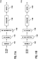
- bit-wise repetition may be performed after error correction encoding and before interleaving as described with reference to FIG. 11A .
- FIG. 11A shows an example of bit-wise repetition performed after forward error correction (FEC) encoding.
- FEC forward error correction
- a SIG field or data is scrambled by a scrambler 1101 and FEC encoded by FEC encoder 1102.
- Bit-wise repetition 1103 is then performed on the output of FEC encoder 1102.
- an interleaver 1104 is applied.
- the interleaver 1104 may have any number of columns (for example, eight columns).
- a mapper 1105 for any modulation scheme, such as BPSK is applied and modulated data may be transmitted.
- bit-wise repetition may be performed before FEC encoding.
- FIG. 11B shows bit-wise repetition performed before FEC encoding.
- bit-wise repetition may be performed before FEC encoding and repeated bits may be separately FEC encoded and interleaved, as described with reference to FIG. 11C .
- FIG. 11C shows bit-wise repetition performed before FEC encoding.
- a SIG field or data is scrambled by a scrambler 1101 and bit-wise repetition 1103 is then performed on the output of the scrambler 1101.
- the output of bit-wise repetition 1103 is then separately FEC encoded and interleaved, whereby FEC encoder 1103 1 and interleaver 1104 1 are applied to a first output of the bit-wise repeater 1102, and FEC encoder 1103 2 and interleaver 1104 2 are applied to a second output of the bit-wise repeater 1102.
- Mapper 1105 is then applied to the output of both interleaver 1104 1 and interleaver 1104 2 , and modulated data may be transmitted.
- block-wise repetition may be performed in place of bit-wise repetition.
- Block-wise repetition may be performed after FEC encoding, as described with reference to FIG. 12 .
- FIG. 12 shows an example of block-wise repetition performed after FEC encoding.
- a scrambler 1201 is applied to a SIG field or data.
- the output of the scrambler 1201 is then FEC encoded by FEC encoder 1202.
- the output of FEC encoder 1202 is then separately block-wise encoded and interleaved, whereby block-wise encoder 1203 1 and interleaver 1204 1 are applied to a first output of the FEC encoder 1202, and block-wise encoder 1203 2 and interleaver 1204 2 are applied to a second output of the FEC encoder 1202.
- the outputs of interleavers 1204 1 and 1204 2 are then combined and provided to mapper 1205 for modulation mapping, and mapped data may be transmitted.
- repetition may be implicitly indicated when bandwidth selection is indicated. For example, if a 1MHz or a 2MHz bandwidth is indicated, then the use of repetition is implicitly indicated, and vice-versa. Further, in IEEE 802.11 communication, the use of repetition may be indicated by an RXVECTOR.
- An RXVECTOR may have a list of parameters that a physical layer (PHY) provides to a local MAC entity. For example, the RXVECTOR may indicate the use of either one of a 1, 2, 4, or 8 MHz bandwidth, or the use of one of a 2, 4, 8, or 16 MHz bandwidth. Further, repetition may be used only when the RXVECTOR indicates the use of either one of a 1, 2, 4, or 8 MHz bandwidth.
- transmit antenna diversity with cyclic shifting may be employed for transmitting a SIG field or data to increase frequency diversity, as described with reference to FIG. 13 .
- the SIG field or data may be bit-wise or block-wise repeated, as described with reference to FIGs. 11A-C and 12 , prior to being transmitted using antenna diversity and cyclic shifting.
- FIG. 13 shows transmission of a SIG field or data using antenna diversity and cyclic shifts.
- a SIG field or data that is an output of FIGs. 11A-C or 12 i.e., a SIG field or data that is scrambled, FEC-encoded, repeated, interleaved, or mapped to a modulation scheme
- the output of the IFFT 1301 is provided to each of four paths.
- a short GI 1303 is inserted, in a second path a first cyclic shift 1302 1 and a short GI 1303 are inserted, in a third path a second cyclic shift 1302 2 and a short GI 1303 are inserted, and in a fourth path a third cyclic shift 1302 3 and a short GI 1303 are inserted.
- data is transmitted using antennas 1304 for each path. It is noted that repetition and frequency diversity gain are achieved because each path receives from the IFFT 1301 a SIG field, a repeated SIG field, or a combination of a SIG field and a repeated SIG field.
- a power headroom report may be requested from a receiver, for example, using a power headroom request, and a power headroom report may be provided by a receiver. If there are multiple receivers in a serving area, a power headroom request may be sent to the multiple receivers, for example, using a power headroom poll.
- a power headroom response may be transmitted using round robin reports or simultaneous reporting using orthogonal reporting, such as orthogonal data signatures. Further, a received signal strength indication (RSSI) or a received channel power indication (RCPI) may be measured based on a preamble or a data transmission, and if the RSSI or RCPI changes from a previous measurement, a correction in transmit power may be determined taking into account the power headroom of multiple receivers.
- RSSI received signal strength indication
- RCPI received channel power indication
- a CRC code for a SIG field of a preamble may be punctured in order to reduce a number of parity bits. By optimally puncturing a CRC code, a shorter code may be generated. For example, an 8-bit CRC code may be punctured to generate a 4-bit CRC code.
- an 8-bit CRC may be generated using the polynomial x 8 + x 2 + x+ 1 for a 26-bit SIG field.
- P is an 8 x 26 matrix
- Is is an 8 x 8 identity matrix.
- P1 is a 4 x 26 matrix
- I 4 is a 4 x 4 identity matrix.
- Table 3 shows a HW distribution for 26 information bits when a 4-bit CRC is derived by puncturing from an 8-bit CRC.
- Table 4 shows a HW distribution for 38 information bits when a 4-bit CRC is derived by puncturing from an 8-bit CRC.
- c 0 represents the most significant bit (MSB) that is punctured
- c 7 represents the least significant bit (LSB) that is punctured.
- Table 3 shows a HW distribution when a 4-bit CRC is derived from an 8-bit CRC for 26 information bits.
- puncturing bits c 7 c 6 c 5 c 4 i.e., the four LSBs
- bits c 3 c 2 c 1 c 0 i.e., the four MSBs
- puncturing bits c 5 c 4 c 2 c 0 since both c 7 c 6 c 5 c 4 and c 3 c 2 c 1 c 0 have a minimum hamming distance of 1.
- any of the puncturing combinations in Tables 3 and 4 may be chosen for a code with a minimum distance 2 to detect all single bit-error patterns.
- the type of modulation used for SIG field symbols may be used to signal information, such as information as to whether beamforming is utilized, for example, a SIG field may comprise any number of OFDM symbols, such as 5 OFDM symbols or 6 OFDM symbols. Further, the 6 OFDM symbols may be modulated using quadrature binary phase shift keying (QBPSK) or binary phase shift keying (BPSK). It is worth noting that according to QBPSK, a symbol is modulated using +/-j, whereas according to BPSK, a symbol is modulated using +/-1.
- QBPSK quadrature binary phase shift keying
- BPSK binary phase shift keying
- the modulation scheme of any one of the OFDM symbols may be used to signal information.
- the modulation scheme of the first OFDM symbol may be used to signal that beamforming is utilized, whereby if the first OFDM symbol is modulation using BPSK, then the use of beamforming is not indicated, whereas if the first OFDM symbol is modulation using QBPSK, then the use of beamforming is indicated.
- the modulation scheme of the OFDM symbols of the SIG field may be used in conjunction with a CRC attachment or FEC encoding to increase the number of information bits signaled using the SIG field.
- FIG. 14A shows an example of coding of SIG field bits.
- X bits of a SIG field are provided to a CRC attachment unit 1401.
- the CRC attachment unit 1401 generates A CRC bits.
- the X+A SIG field bits and CRC attachment bits are provided to an FEC encoder 1402 to generate an output.
- the output of the FEC encoder 1402 is then provided to a repeater, interleaver, and mapper unit 1403, and the encoded and modulated X+A field bits and CRC attachment bits may be transmitted.
- the number of bits signaled using the SIG field may be increased from X to X+Y while protecting the additional Y SIG fields using CRC encoding as described with reference to FIG. 14B .
- FIG. 14B shows an example of coding of SIG field bits and additional bits.
- X SIG field bits and Y additional SIG field bits are provided to a CRC attachment unit 1401.
- the CRC attachment unit 1401 generates A CRC attachment bits based on both the X SIG field bits and Y additional SIG field bits, and provides an output of X+Y+A bits.
- the X+A bits pertaining to the SIG field and CRC attachment are provided to an FEC encoder 1402 to generate an output.
- the output of the FEC encoder 1402 is provided to a repeater, interleaver, and mapper unit 1403 in the same manner as described with reference to FIG. 14A .
- the Y additional bits may not be transmitted in the same manner as the X+A bits pertaining to the SIG field and CRC attachment. Instead, the Y additional bits may be provided to a SIG symbol modulation unit 1404, which modulates the Y bits using the SIG field OFDM symbols as described above. For example, if the Y bits are [0 0 1 1 1], then five SIG field OFDM symbols may be modulated as [QQBBB] to indicate the Y bits, where a QBPSK modulation of a SIG field symbol indicates a zero bit and a BPSK modulation indicates a 1 bit.
- the Y additional bits are protected using the A CRC attachment bits. Further, no additional overhead is needed for signaling the Y additional bits. Further, in addition to CRC attachment, the Y additional bits may also be protected by an FEC code, as described with reference to FIG. 14C .
- FIG. 14C shows an example of coding of SIG field bits and additional bits.
- X SIG field bits and Y additional bits are provided to a CRC attachment unit 1401.
- the CRC attachment unit 1401 generates A CRC bits and provides an output of X+Y+A bits to the FEC encoder 1402, which generates an output.
- a first portion of the output of the FEC encoder 1402 is provided to a repeater, interleaver, and mapper unit 1403 and a second portion of the output of the FEC encoder 1402 (for example, 5 or 6 bits) is provided to a SIG symbol modulation unit 1404, which modulates the Y bits using the SIG field OFDM symbols as described above.
- the modulation scheme of the OFDM symbols of the SIG field may be used to introduce more CRC attachment bits in order to improve the robustness of the CRC attachment.
- the CRC attachment may be increased from A bits to A+B bits.
- the additional B CRCs bits may signaled using the modulation of the OFDM symbols.
- the additional B CRC bits may be further coded using any coding scheme as described with reference to FIG. 14D .
- FIG. 14D shows an example of coding of SIG field bits and additional CRC bits.
- X SIG field bits are provided to a CRC attachment unit 1401.
- the CRC attachment unit 1401 generates a CRC attachment of A+B bits (i.e., the CRC attachment unit 1401 generates B additional attachment bits than shown in FIGs. 14A-C ).
- the X SIG field bits and the A CRC attachment bits are provided to FEC encoder 1402 to generate an output.
- the output of the FEC encoder 1402 is provided to a repeater, interleaver, and mapper unit 1403, and may then be transmitted.
- the B CRC attachment bits are provided to a (B,Z) encoder 1405.
- ROM read only memory
- RAM random access memory
- register cache memory
- semiconductor memory devices magnetic media such as internal hard disks and removable disks, magneto-optical media, and optical media such as CD-ROM disks, and digital versatile disks (DVDs).
- a processor in association with software may be used to implement a radio frequency transceiver for use in a WTRU, UE, terminal, base station, RNC, or any host computer.
Claims (13)
- Station, STA, comprenant :
un émetteur-récepteur configuré pour recevoir une transmission, la transmission incluant un préambule (701) et de multiples champs de données (702, 704, 706), où le préambule inclut un champ de signal, SIG, (701A), le champ SIG incluant une indication d'au moins un midambule (703) présent parmi les champs de données et une indication d'emplacement de midambule parmi les champs de données ; et un processeur couplé opérationnellement à l'émetteur-récepteur, le processeur étant configuré pour décoder les champs de données, sur la base du champ SIG. - STA selon la revendication 1, dans laquelle l'indication d'emplacement de midambule fournit un décalage de symbole de l'au moins un midambule.
- STA selon la revendication 1, dans laquelle l'indication d'emplacement de midambule fournit un décalage de symbole entre un premier midambule et un deuxième midambule.
- STA selon la revendication 1, dans laquelle l'indication d'emplacement de midambule indique un indice d'un emplacement prédéterminé de l'au moins un midambule.
- STA selon la revendication 1, dans laquelle le processeur et l'émetteur-récepteur sont en outre configurés pour interpoler des estimations de canal obtenues sur la base de l'au moins un midambule parmi les champs de données.
- STA selon la revendication 5, dans laquelle le processeur et l'émetteur-récepteur sont en outre configurés pour obtenir une estimation Doppler d'un canal sur la base de l'au moins un midambule, et envoyer l'estimation Doppler à un émetteur.
- STA selon la revendication 1, dans laquelle l'au moins un midambule est utilisable pour faciliter la mise à jour d'une estimation de canal.
- STA selon la revendication 1, dans laquelle le processeur et l'émetteur-récepteur sont en outre configurés pour transmettre une demande d'augmentation ou de réduction du nombre de midambules sur la base d'une estimation de canal Doppler.
- Procédé réalisé par une STA, le procédé comprenant :la réception, par l'intermédiaire d'un émetteur-récepteur, d'une transmission incluant un préambule (701) et de multiples champs de données (702, 704, 706), où le préambule inclut un champ de signal, SIG, (701A), le champ SIG incluant une indication d'au moins un midambule (703) présent parmi les champs de données et une indication d'emplacement de midambule parmi les champs de données ; etle décodage, par l'intermédiaire d'un processeur, des champs de données, sur la base du champ SIG.
- Procédé selon la revendication 9, dans lequel l'indication d'emplacement de midambule fournit au moins l'un parmi un décalage de symbole de l'au moins un midambule, un décalage de symbole entre un premier midambule et un deuxième midambule, et un indice d'un emplacement prédéterminé de l'au moins un midambule.
- Procédé selon la revendication 9, comprenant en outre :
l'interpolation d'estimations de canal obtenues sur la base de l'au moins un midambule parmi les champs de données. - Procédé selon la revendication 11, comprenant en outre :
la transmission d'une estimation Doppler d'un canal à un émetteur, où l'estimation Doppler est obtenue sur la base de l'au moins un midambule. - Procédé selon la revendication 9, comprenant en outre la transmission d'une demande d'augmentation ou de réduction du nombre de midambules sur la base d'une estimation de canal Doppler.
Priority Applications (1)
| Application Number | Priority Date | Filing Date | Title |
|---|---|---|---|
| EP23153115.3A EP4221045A1 (fr) | 2011-06-24 | 2012-06-22 | Procédé et appareil de réception de préambule dans un système de communication sans fil |
Applications Claiming Priority (5)
| Application Number | Priority Date | Filing Date | Title |
|---|---|---|---|
| US201161500930P | 2011-06-24 | 2011-06-24 | |
| US201261586525P | 2012-01-13 | 2012-01-13 | |
| US201261607345P | 2012-03-06 | 2012-03-06 | |
| US201261645948P | 2012-05-11 | 2012-05-11 | |
| PCT/US2012/043725 WO2012177993A1 (fr) | 2011-06-24 | 2012-06-22 | Procédé et appareil pour recevoir un préambule dans un système de communication sans fil |
Related Child Applications (1)
| Application Number | Title | Priority Date | Filing Date |
|---|---|---|---|
| EP23153115.3A Division EP4221045A1 (fr) | 2011-06-24 | 2012-06-22 | Procédé et appareil de réception de préambule dans un système de communication sans fil |
Publications (2)
| Publication Number | Publication Date |
|---|---|
| EP2724488A1 EP2724488A1 (fr) | 2014-04-30 |
| EP2724488B1 true EP2724488B1 (fr) | 2023-01-25 |
Family
ID=46466909
Family Applications (2)
| Application Number | Title | Priority Date | Filing Date |
|---|---|---|---|
| EP23153115.3A Pending EP4221045A1 (fr) | 2011-06-24 | 2012-06-22 | Procédé et appareil de réception de préambule dans un système de communication sans fil |
| EP12733335.9A Active EP2724488B1 (fr) | 2011-06-24 | 2012-06-22 | Procédé et appareil de réception de préambule dans un système de communication sans fil |
Family Applications Before (1)
| Application Number | Title | Priority Date | Filing Date |
|---|---|---|---|
| EP23153115.3A Pending EP4221045A1 (fr) | 2011-06-24 | 2012-06-22 | Procédé et appareil de réception de préambule dans un système de communication sans fil |
Country Status (5)
| Country | Link |
|---|---|
| US (3) | US20120327871A1 (fr) |
| EP (2) | EP4221045A1 (fr) |
| KR (2) | KR102273748B1 (fr) |
| TW (1) | TWI574533B (fr) |
| WO (1) | WO2012177993A1 (fr) |
Families Citing this family (101)
| Publication number | Priority date | Publication date | Assignee | Title |
|---|---|---|---|---|
| JP5251605B2 (ja) * | 2009-03-02 | 2013-07-31 | ソニー株式会社 | 通信装置、および利得制御方法 |
| US8615023B2 (en) * | 2010-10-27 | 2013-12-24 | Electronics And Telecommunications Research Institute | Apparatus and method for transmitting/receiving data in communication system |
| US8885740B2 (en) | 2011-02-04 | 2014-11-11 | Marvell World Trade Ltd. | Control mode PHY for WLAN |
| US20120263141A1 (en) * | 2011-04-15 | 2012-10-18 | Qualcomm Incorporated | Systems and methods for range extension of wireless communication in sub gigahertz bands |
| US10530430B2 (en) * | 2011-04-24 | 2020-01-07 | Avago Technologies International Sales Pte. Limited | Doppler midamble signaling for wireless communications |
| TWI574533B (zh) * | 2011-06-24 | 2017-03-11 | 內數位專利控股公司 | 用於在多用戶多輸入多輸出通訊中接收前導碼的方法及無線傳輸/接收單元 |
| KR101624817B1 (ko) * | 2011-11-24 | 2016-05-26 | 엘지전자 주식회사 | 무선랜 시스템에서 채널 사운딩 수행 방법 및 이를 지원하는 장치 |
| US9071489B2 (en) * | 2011-12-07 | 2015-06-30 | Futurewei Technologies, Inc. | System and method for preambles in a wireless communications network |
| US9088504B2 (en) * | 2012-01-06 | 2015-07-21 | Qualcomm Incorporated | Systems and methods for wireless communication of long data units |
| EP2803175B1 (fr) * | 2012-01-13 | 2019-06-05 | Marvell World Trade Ltd. | Format d'unité de données pour formation de faisceau mono-utilisateur dans des réseaux locaux sans fil (wlan) à longue portée |
| US9100947B2 (en) | 2012-04-02 | 2015-08-04 | Qualcomm Incorporated | Modulation and coding schemes in sub-1 GHz networks |
| US9179496B2 (en) * | 2012-04-02 | 2015-11-03 | Qualcomm Incorporated | Tone scaling parameters in Sub-1 GHz networks |
| US9055468B2 (en) | 2012-04-02 | 2015-06-09 | Qualcomm Incorporated | Frame formats and timing parameters in sub-1 GHz networks |
| WO2013152111A1 (fr) | 2012-04-03 | 2013-10-10 | Marvell World Trade Ltd. | Format de trame de couche physique pour wlan |
| EP2661033B1 (fr) | 2012-05-03 | 2018-07-11 | MediaTek Singapore Pte Ltd. | Indication de changement de faisceau pour améliorer l'estimation de canal dans des réseaux sans fil |
| KR20130142932A (ko) * | 2012-06-19 | 2013-12-30 | 한국전자통신연구원 | 무선랜 시스템의 오에프디엠 전송 방법 및 장치 |
| US9008167B2 (en) | 2012-12-29 | 2015-04-14 | Intel Corporation | Methods and arrangements for phase tracking for multi-mode operation in wireless networks |
| GB201302414D0 (en) | 2013-02-12 | 2013-03-27 | Sepura Ltd | Mobile communication system |
| DK2957082T3 (da) * | 2013-02-12 | 2020-05-25 | Sepura Ltd | Tetra-baseret mobilkommunikationssystem |
| US9414432B2 (en) | 2013-04-03 | 2016-08-09 | Marvell World Trade Ltd. | Physical layer frame format for WLAN |
| KR20140125112A (ko) * | 2013-04-18 | 2014-10-28 | 한국전자통신연구원 | 무선 lan 시스템에서 시그널 필드의 채널 정보를 이용하여 채널을 추정하는 방법 및 시스템 |
| EP2991396B1 (fr) * | 2013-04-22 | 2019-04-03 | LG Electronics Inc. | Procédé de signalement d'une marge de puissance dans un système de communication sans fil qui supporte un changement d'utilisation des ressources sans fil et appareil associé |
| US9860102B2 (en) * | 2013-07-05 | 2018-01-02 | Electronics & Telecommunications Research Institute | Method for transmitting signal in communication system |
| US9780919B2 (en) * | 2013-07-05 | 2017-10-03 | Quallcomm, Incorporated | High efficiency WLAN preamble structure |
| US9462575B2 (en) | 2013-08-28 | 2016-10-04 | Qualcomm Incorporated | Low rate data communication |
| KR20210153759A (ko) | 2013-09-10 | 2021-12-17 | 마벨 아시아 피티이 엘티디. | 옥외 wlan용 확장 보호 구간 |
| US10194006B2 (en) | 2013-10-25 | 2019-01-29 | Marvell World Trade Ltd. | Physical layer frame format for WLAN |
| US10218822B2 (en) | 2013-10-25 | 2019-02-26 | Marvell World Trade Ltd. | Physical layer frame format for WLAN |
| KR102526618B1 (ko) | 2013-10-25 | 2023-04-27 | 마벨 아시아 피티이 엘티디. | 와이파이를 위한 레인지 확장 모드 |
| KR101741512B1 (ko) * | 2013-12-19 | 2017-05-31 | 한국해양과학기술원 | 패킷 통신용 수신기의 채널 등화 및 수신 데이터 결정 장치 및 방법 |
| US9712342B2 (en) * | 2014-04-11 | 2017-07-18 | Newracom, Inc. | Frame transmitting method and frame receiving method |
| US11855818B1 (en) * | 2014-04-30 | 2023-12-26 | Marvell Asia Pte Ltd | Adaptive orthogonal frequency division multiplexing (OFDM) numerology in a wireless communication network |
| WO2015168639A1 (fr) | 2014-05-02 | 2015-11-05 | Marvell World Trade Ltd. | Signalisation d'attribution d'utilisateurs multiples dans un réseau de communication sans fil |
| EP3155779B1 (fr) | 2014-06-11 | 2019-10-16 | Marvell World Trade Ltd. | Preambule comprime pour un systeme de communication sans fil |
| WO2016017946A1 (fr) * | 2014-07-28 | 2016-02-04 | 엘지전자(주) | Dispositif et procédé de transmission et de réception dans un système de communications sans fil |
| CN106716944B (zh) * | 2014-08-04 | 2020-09-08 | 英特尔Ip公司 | 用于hew中的字段的无线设备、方法和计算机可读介质 |
| JP6321285B2 (ja) | 2014-08-06 | 2018-05-09 | エルジー エレクトロニクス インコーポレイティド | 無線lanにおけるデータの送信または受信のための無線リソースを割り当てる方法及び装置 |
| CN111711591B (zh) * | 2014-08-25 | 2023-06-02 | 韦勒斯标准与技术协会公司 | 无线通信方法及使用该方法的无线通信终端 |
| KR102045659B1 (ko) * | 2014-09-12 | 2019-11-15 | 인터디지탈 패튼 홀딩스, 인크 | 무선 근거리 네트워크 시스템에서 동시 송신들에 대한 프리앰블 선택 |
| US10506556B2 (en) | 2014-09-13 | 2019-12-10 | Lg Electronics Inc. | Method and device for allocating resource units in wireless LAN |
| WO2016056799A1 (fr) * | 2014-10-05 | 2016-04-14 | 엘지전자 주식회사 | Procédé de génération de séquence de préambule dans un système de réseau local sans fil |
| US10200165B2 (en) * | 2014-10-06 | 2019-02-05 | Newracom, Inc. | Beamformed transmission in high efficiency wireless LAN |
| US20160119171A1 (en) * | 2014-10-28 | 2016-04-28 | Huawei Technologies Co., Ltd. | System and Method for Wireless Communication Using Space-Time Block Code Encoding |
| US10484222B2 (en) * | 2014-10-14 | 2019-11-19 | Wilus Institute Of Standards And Technology Inc. | Wireless communication method and wireless communication terminal |
| EP3214870B1 (fr) * | 2014-10-31 | 2021-09-29 | Sony Group Corporation | Dispositif de communication et procédé de communication |
| WO2016072766A1 (fr) * | 2014-11-05 | 2016-05-12 | 엘지전자 주식회사 | Procédé et dispositif d'attribution d'unité de ressource sur la base d'un conteneur dans un lan sans fil |
| WO2016085241A1 (fr) * | 2014-11-24 | 2016-06-02 | 엘지전자 주식회사 | Procédé et dispositif d'attribution d'unités de ressources au moyen de tonalités inutilisées dans un lan sans fil |
| US9924510B2 (en) * | 2014-12-03 | 2018-03-20 | Intel IP Corporation | Wireless device, method, and computer readable media for orthogonal frequency division multiple access (OFDMA) allocations based on a basic tone resource unit or entire sub-channel |
| EP4274152A3 (fr) * | 2014-12-05 | 2024-02-28 | LG Electronics Inc. | Procédé pour transmettre/recevoir une unité de données de protocole physique (ppdu) dans un système de communication sans fil et appareil associé |
| WO2016106753A1 (fr) * | 2014-12-31 | 2016-07-07 | 华为技术有限公司 | Procédé et appareil d'estimation de canal pour réseau local sans fil |
| US20160197755A1 (en) * | 2015-01-07 | 2016-07-07 | Qualcomm Incorporated | Deferral Information in Postambles and Midambles |
| WO2016112287A1 (fr) | 2015-01-09 | 2016-07-14 | Interdigital Patent Holdings, Inc. | Procédés, appareils et systèmes permettant la prise en charge de transmissions multi-utilisateurs dans un système de réseau local sans fil (wlan) |
| US9806927B2 (en) | 2015-01-21 | 2017-10-31 | Intel IP Corporation | Method, apparatus, and computer readable medium for signaling high efficiency packet formats using a legacy portion of the preamble in wireless local-area networks |
| US9847896B2 (en) * | 2015-01-21 | 2017-12-19 | Intel IP Corporation | Method, apparatus, and computer readable medium for signaling high efficiency packet formats using a legacy portion of the preamble in wireless local-area networks |
| RU2019102777A (ru) * | 2015-01-22 | 2019-02-28 | Хуавей Текнолоджиз Ко., Лтд. | Способ и устройство для индикации структуры кадра передачи и система |
| US10419971B2 (en) * | 2015-02-04 | 2019-09-17 | Qualcomm Incorporated | Robust early detection through signal repetition in mixed-rate wireless communications |
| US9674011B1 (en) | 2015-02-10 | 2017-06-06 | Marvel International Ltd. | Auto-detection of repeated signals |
| KR102296339B1 (ko) * | 2015-02-17 | 2021-09-01 | 주식회사 윌러스표준기술연구소 | 다중 사용자 전송을 위한 시그널링 방법 및 이를 이용한 무선 통신 단말과 무선 통신 방법 |
| US10218555B2 (en) | 2015-03-06 | 2019-02-26 | Intel IP Corporation | Usage of early bits in wireless communications |
| US10382598B1 (en) | 2015-05-01 | 2019-08-13 | Marvell International Ltd. | Physical layer frame format for WLAN |
| US10181966B1 (en) | 2015-05-01 | 2019-01-15 | Marvell International Ltd. | WiFi classification by pilot sequences |
| ES2847801T3 (es) | 2015-06-03 | 2021-08-03 | Apple Inc | Dispositivo de transmisión y método de transmisión para unidad de datos de protocolo de capa física agregada |
| WO2016200020A1 (fr) * | 2015-06-11 | 2016-12-15 | 엘지전자 주식회사 | Procédé pour émettre et recevoir un signal dans un système de réseau local (lan) sans fil et appareil associé |
| US10038518B1 (en) | 2015-06-11 | 2018-07-31 | Marvell International Ltd. | Signaling phy preamble formats |
| CN105099621B (zh) * | 2015-06-29 | 2018-05-22 | 珠海市魅族科技有限公司 | 通信方法和通信设备 |
| KR102479074B1 (ko) * | 2015-06-29 | 2022-12-20 | 주식회사 윌러스표준기술연구소 | 레거시 무선 통신 단말과 공존을 위한 무선 통신 방법 및 무선 통신 단말 |
| CN108551434B (zh) | 2015-08-26 | 2019-04-12 | 华为技术有限公司 | 传输he-ltf序列的方法和装置 |
| WO2017073976A1 (fr) * | 2015-10-26 | 2017-05-04 | 엘지전자 주식회사 | Procédé pour émettre un signal ayant une certaine robustesse dans un système de communication mobile et appareil associé |
| EP3832915B1 (fr) | 2015-11-04 | 2023-09-06 | Panasonic Intellectual Property Management Co., Ltd. | Appareil et procédé de transmission de signalisation de commande dans un système de communication sans fil |
| CN108540412B (zh) | 2015-11-23 | 2019-03-26 | 华为技术有限公司 | 无线局域网数据传输方法和装置 |
| US20170207905A1 (en) * | 2016-01-14 | 2017-07-20 | Qualcomm Incorporated | Fly feedback |
| WO2017160774A1 (fr) * | 2016-03-15 | 2017-09-21 | Qualcomm Incorporated | Structure de trame de faible puissance à longue portée |
| US10608720B2 (en) * | 2016-11-20 | 2020-03-31 | Qualcomm Incorporated | Indicating support for communication using mid-ambles |
| US20180146076A1 (en) * | 2016-11-20 | 2018-05-24 | Qualcomm Incorporated | Indicating presence of mid-amble |
| US10419186B2 (en) * | 2016-11-20 | 2019-09-17 | Qualcomm Incorporated | Mobility communication using mid-ambles |
| CN108123777A (zh) * | 2016-11-30 | 2018-06-05 | 华为技术有限公司 | 一种编码方式确定方法及装置 |
| US10257012B2 (en) | 2016-12-13 | 2019-04-09 | Samsung Electronics Co., Ltd | Apparatus and method for coarse timing and frequency synchronization |
| US10575267B2 (en) * | 2017-01-05 | 2020-02-25 | Samsung Electronics Co., Ltd | System and method for providing weighted pattern demapper for Bluetooth® low energy long range |
| US10568102B2 (en) * | 2017-02-23 | 2020-02-18 | Qualcomm Incorporated | Usage of synchronization signal block index in new radio |
| TWI641240B (zh) * | 2017-04-07 | 2018-11-11 | 濎通科技股份有限公司 | 電力線通信裝置及方法 |
| CN115051897A (zh) * | 2017-05-02 | 2022-09-13 | 交互数字专利控股公司 | 针对单用户和多用户传输的波形编码以及调制 |
| US10749996B2 (en) * | 2017-05-26 | 2020-08-18 | Newracom, Inc. | Doppler mode in a wireless network |
| EP3635926B1 (fr) | 2017-06-09 | 2024-03-27 | Marvell World Trade Ltd. | Paquets à midambules ayant des symboles ofdm comprimés |
| CN116208460A (zh) | 2017-07-04 | 2023-06-02 | 华为技术有限公司 | 一种数据处理方法和装置 |
| US10999110B2 (en) * | 2017-07-07 | 2021-05-04 | Qualcomm Incorporated | Techniques for selecting PPDU format parameters |
| WO2019045708A1 (fr) * | 2017-08-30 | 2019-03-07 | Intel IP Corporation | Procédés et systèmes pour le wi-fi nouvelle génération |
| WO2019060407A1 (fr) * | 2017-09-22 | 2019-03-28 | Marvell World Trade Ltd. | Détermination du nombre de midambules dans un paquet |
| WO2019098713A1 (fr) | 2017-11-15 | 2019-05-23 | 엘지전자 주식회사 | Procédé permettant d'effectuer une transmission précoce de données pendant d'une procédure d'accès aléatoire dans un système de communication sans fil, et appareil pour cela |
| JP7230054B2 (ja) | 2017-12-06 | 2023-02-28 | マーベル アジア ピーティーイー、リミテッド | 車両環境の物理層プロトコルデータユニットを生成するための方法および装置 |
| US10742353B2 (en) * | 2018-04-09 | 2020-08-11 | Qualcomm Incorporated | Cross-correlation reduction for control signals |
| WO2019207425A1 (fr) | 2018-04-26 | 2019-10-31 | Marvell World Trade Ltd. | Pilotes d'accès sans fil dans des environnements véhiculaires |
| CN109873691A (zh) * | 2019-02-18 | 2019-06-11 | 内蒙古伊泰准东铁路有限责任公司 | 列车尾部装置运行监控信息方法及系统 |
| US10873947B2 (en) | 2019-02-27 | 2020-12-22 | Cisco Technology, Inc. | Internet of things (IoT) device location tracking using midambles |
| CN113892250A (zh) | 2019-04-09 | 2022-01-04 | 马维尔亚洲私人有限公司 | 在车辆通信网络中的复合通信信道中的物理层数据单元的生成和传输 |
| US10707904B1 (en) * | 2019-05-02 | 2020-07-07 | SatixFy Isreal Ltd. | Methods and devices for operating in beam hopping configuration and under a range of signal to noise ratio conditions |
| CN113796053B (zh) | 2019-05-07 | 2023-10-17 | Lg 电子株式会社 | 在无线通信系统中发送中置的技术 |
| US11533592B2 (en) | 2019-09-06 | 2022-12-20 | Marvell Asia Pte Ltd | Midamble format for packets in a vehicular communication network |
| CN114696943B (zh) * | 2020-12-25 | 2024-03-01 | 大唐移动通信设备有限公司 | 序列传输方法、接收方法、终端、网络设备和存储介质 |
| CN115086924A (zh) * | 2021-03-12 | 2022-09-20 | 华为技术有限公司 | 蓝牙通信方法、系统及电子设备 |
| US11558232B1 (en) * | 2021-09-30 | 2023-01-17 | Silicon Laboratories Inc. | Generating a preamble portion of an orthogonal frequency division multiplexing transmission using complex sequence values optimized for minimum Peak-to-Average Power Ratio |
| CN117097446A (zh) * | 2022-05-11 | 2023-11-21 | 华为技术有限公司 | 基于物理层协议数据单元的通信方法及装置 |
Citations (5)
| Publication number | Priority date | Publication date | Assignee | Title |
|---|---|---|---|---|
| US20110032875A1 (en) * | 2009-08-07 | 2011-02-10 | Broadcom Corporation | Distributed signal field for communications within multiple user, multiple access, and/or MIMO wireless communications |
| WO2011031058A2 (fr) * | 2009-09-09 | 2011-03-17 | Lg Electronics Inc. | Procédé et appareil de transmission d'informations de commande dans un système wlan |
| US20110096796A1 (en) * | 2009-10-23 | 2011-04-28 | Hongyuan Zhang | Number of streams indication for wlan |
| US20110103280A1 (en) * | 2009-11-03 | 2011-05-05 | Yong Liu | Power Saving in a Communication Device |
| US20110150148A1 (en) * | 2009-12-18 | 2011-06-23 | Electronics And Telecommuniations Research Institute | Apparatus and method for detecting signal in wireless communication system |
Family Cites Families (36)
| Publication number | Priority date | Publication date | Assignee | Title |
|---|---|---|---|---|
| WO2005112355A1 (fr) * | 2004-05-13 | 2005-11-24 | Koninklijke Philips Electronics N.V. | Agregation de recepteurs multiples (mra) avec differents debits binaires pour ieee 802.11n |
| WO2006079950A1 (fr) * | 2005-01-31 | 2006-08-03 | Koninklijke Philips Electronics N.V. | Procede et dispositif reposant sur l'emploi de sequences d'apprentissage de longueur variable en radio communication |
| KR100643299B1 (ko) * | 2005-06-09 | 2006-11-10 | 삼성전자주식회사 | 고속 무선 네트워크에서 레거시 방식의 데이터를송수신하는 방법 및 장치 |
| JP4841333B2 (ja) * | 2005-09-19 | 2011-12-21 | 三洋電機株式会社 | 無線装置およびそれを利用した通信システム |
| US8989290B2 (en) * | 2007-06-27 | 2015-03-24 | Unwired Planet, Llc | Mode switching between SU-MIMO and MU-MIMO |
| KR101323089B1 (ko) * | 2007-08-07 | 2013-10-29 | 엘지전자 주식회사 | Tdd 무선 통신 시스템에서 제어 정보의 전송 방법 |
| KR101336961B1 (ko) * | 2008-04-17 | 2013-12-04 | 삼성전자주식회사 | 다중 입출력 무선통신 시스템에서 미드앰블을 이용한프리코딩 장치 및 방법 |
| US8982889B2 (en) * | 2008-07-18 | 2015-03-17 | Marvell World Trade Ltd. | Preamble designs for sub-1GHz frequency bands |
| JP4666031B2 (ja) * | 2008-09-09 | 2011-04-06 | ソニー株式会社 | 同期回路並びに無線通信装置 |
| US8830973B2 (en) * | 2009-02-18 | 2014-09-09 | Lg Electronics Inc. | Coexistent channel access method |
| TWI596969B (zh) * | 2009-03-17 | 2017-08-21 | 內數位專利控股公司 | 在多輸入多輸出中上鏈功率控制方法和裝置 |
| CN101867551B (zh) * | 2009-06-03 | 2015-09-02 | 开曼群岛威睿电通股份有限公司 | 多输入多输出正交频分多址技术和前同步码设计 |
| US20100329236A1 (en) * | 2009-06-26 | 2010-12-30 | Qualcomm Incorporated | Method and apparatus for multiple user uplink requiring minimal station timing and frequency synchronization |
| US8432982B2 (en) * | 2009-06-29 | 2013-04-30 | Samsung Electronics Co., Ltd. | Techniques for estimating channel and interference in OFDM wireless communication system with multiple antennas |
| US8462863B1 (en) * | 2009-07-23 | 2013-06-11 | Marvell International Ltd. | Midamble for WLAN PHY frames |
| US8681815B1 (en) * | 2009-08-28 | 2014-03-25 | Marvell International Ltd. | Method and apparatus for multi-user frame aggregation |
| US9042331B2 (en) * | 2009-09-09 | 2015-05-26 | Lg Electronics Inc. | Method and apparatus for transmitting control information in WLAN system |
| KR20110030272A (ko) * | 2009-09-17 | 2011-03-23 | 엘지전자 주식회사 | 프레임 전송방법 및 이를 지원하는 장치 |
| KR20110027539A (ko) * | 2009-09-09 | 2011-03-16 | 엘지전자 주식회사 | 무선랜 시스템에서의 제어신호 전송방법 및 이를 지원하는 장치 |
| US8681757B2 (en) * | 2009-11-09 | 2014-03-25 | Lg Electronics Inc. | Method and apparatus for transmitting PLCP frame in wireless local area network system |
| US8434336B2 (en) * | 2009-11-14 | 2013-05-07 | Qualcomm Incorporated | Method and apparatus for managing client initiated transmissions in multiple-user communication schemes |
| US8675575B2 (en) * | 2009-12-23 | 2014-03-18 | Intel Corporation | Scheduling mechanisms for media access control protection and channel sounding |
| JP5108035B2 (ja) * | 2010-01-06 | 2012-12-26 | 株式会社エヌ・ティ・ティ・ドコモ | 基地局装置、移動局装置及び制御情報送信方法 |
| EP2632059A1 (fr) * | 2010-04-02 | 2013-08-28 | Interdigital Patent Holdings, Inc. | Système et procédés de fonctionnement MIMO multi-utilisateur HSDPA |
| US8654663B2 (en) * | 2010-04-05 | 2014-02-18 | Nec Laboratories America, Inc. | MU-MIMO-OFDMA systems and methods for multi-rank CQI computation and precoder selection |
| US9025428B2 (en) * | 2010-04-14 | 2015-05-05 | Qualcomm Incorporated | Allocating and receiving tones for a frame |
| US8498245B2 (en) * | 2010-05-15 | 2013-07-30 | Ralink Technology Corp. | Method of arranging packets in a wireless communication system and related device |
| US9860037B2 (en) * | 2010-07-21 | 2018-01-02 | Qualcomm, Incorporated | Method and apparatus for ordering sub-fields of VHT-SIG-A and VIT-SIG-B fields |
| EP2643935B1 (fr) * | 2010-11-26 | 2019-09-11 | LG Electronics Inc. | Procédé de rapport d'informations de canal sur la base d'une adaptation de liaison dans un réseau local sans fil et appareil correspondant |
| US9184969B2 (en) * | 2011-04-24 | 2015-11-10 | Broadcom Corporation | Preamble for use within single user, multiple user, multiple access, and/or MIMO wireless communications |
| US20120269142A1 (en) * | 2011-04-24 | 2012-10-25 | Broadcom Corporation | Doppler adaptation using pilot patterns within single user, multiple user, multiple access, and/or MIMO wireless communications |
| US9385911B2 (en) * | 2011-05-13 | 2016-07-05 | Sameer Vermani | Systems and methods for wireless communication of packets having a plurality of formats |
| US8830815B2 (en) * | 2011-05-19 | 2014-09-09 | Qualcomm Incorporated | Preamble design for television white space transmissions |
| TWI574533B (zh) * | 2011-06-24 | 2017-03-11 | 內數位專利控股公司 | 用於在多用戶多輸入多輸出通訊中接收前導碼的方法及無線傳輸/接收單元 |
| US9455857B2 (en) * | 2012-03-30 | 2016-09-27 | Lg Electronics Inc. | Method for transmitting data unit in wireless LAN system and device for supporting same |
| US20130279379A1 (en) * | 2012-04-24 | 2013-10-24 | Qualcomm Incorporated | Systems and methods for wireless communication of long data units |
-
2012
- 2012-06-22 TW TW101122387A patent/TWI574533B/zh not_active IP Right Cessation
- 2012-06-22 EP EP23153115.3A patent/EP4221045A1/fr active Pending
- 2012-06-22 EP EP12733335.9A patent/EP2724488B1/fr active Active
- 2012-06-22 KR KR1020207036812A patent/KR102273748B1/ko active IP Right Grant
- 2012-06-22 US US13/530,576 patent/US20120327871A1/en not_active Abandoned
- 2012-06-22 WO PCT/US2012/043725 patent/WO2012177993A1/fr unknown
- 2012-06-22 KR KR20147001934A patent/KR20140053128A/ko active Application Filing
-
2018
- 2018-12-07 US US16/213,633 patent/US11611414B2/en active Active
-
2023
- 2023-03-20 US US18/186,632 patent/US20230231669A1/en active Pending
Patent Citations (5)
| Publication number | Priority date | Publication date | Assignee | Title |
|---|---|---|---|---|
| US20110032875A1 (en) * | 2009-08-07 | 2011-02-10 | Broadcom Corporation | Distributed signal field for communications within multiple user, multiple access, and/or MIMO wireless communications |
| WO2011031058A2 (fr) * | 2009-09-09 | 2011-03-17 | Lg Electronics Inc. | Procédé et appareil de transmission d'informations de commande dans un système wlan |
| US20110096796A1 (en) * | 2009-10-23 | 2011-04-28 | Hongyuan Zhang | Number of streams indication for wlan |
| US20110103280A1 (en) * | 2009-11-03 | 2011-05-05 | Yong Liu | Power Saving in a Communication Device |
| US20110150148A1 (en) * | 2009-12-18 | 2011-06-23 | Electronics And Telecommuniations Research Institute | Apparatus and method for detecting signal in wireless communication system |
Also Published As
| Publication number | Publication date |
|---|---|
| EP2724488A1 (fr) | 2014-04-30 |
| US20190109681A1 (en) | 2019-04-11 |
| US11611414B2 (en) | 2023-03-21 |
| US20120327871A1 (en) | 2012-12-27 |
| US20230231669A1 (en) | 2023-07-20 |
| EP4221045A1 (fr) | 2023-08-02 |
| KR20140053128A (ko) | 2014-05-07 |
| WO2012177993A1 (fr) | 2012-12-27 |
| TWI574533B (zh) | 2017-03-11 |
| KR20210005958A (ko) | 2021-01-15 |
| KR102273748B1 (ko) | 2021-07-06 |
| TW201308960A (zh) | 2013-02-16 |
Similar Documents
| Publication | Publication Date | Title |
|---|---|---|
| US20230231669A1 (en) | Non-legacy preamble for wireless local area networks | |
| US20230275695A1 (en) | Waveform based data integrity check and error correction | |
| US9667465B2 (en) | Systems and methods for wireless communication in sub gigahertz bands | |
| EP2754276B1 (fr) | Interprétation double d'un champ de longueur d'une unité de signal | |
| US9088504B2 (en) | Systems and methods for wireless communication of long data units | |
| KR101576172B1 (ko) | 제로-길이 페이로드를 나타내는 필드를 포함하는 신호 유닛 | |
| KR20160030521A (ko) | 고효율 wlan 프리앰블 구조 | |
| US20130286961A1 (en) | Systems and methods for wireless communication of long data units | |
| US20130107981A1 (en) | Systems and methods for wireless communication of long data units | |
| US20130279379A1 (en) | Systems and methods for wireless communication of long data units | |
| US20220255693A1 (en) | Backward compatible physical layer convergence procedure (plcp) protocol data unit (ppdu) design in wireless local area network (wlan) system | |
| KR20150111968A (ko) | Wifi 대역들에서 범위 및 지연 확산의 확장 |
Legal Events
| Date | Code | Title | Description |
|---|---|---|---|
| PUAI | Public reference made under article 153(3) epc to a published international application that has entered the european phase |
Free format text: ORIGINAL CODE: 0009012 |
|
| 17P | Request for examination filed |
Effective date: 20140110 |
|
| AK | Designated contracting states |
Kind code of ref document: A1 Designated state(s): AL AT BE BG CH CY CZ DE DK EE ES FI FR GB GR HR HU IE IS IT LI LT LU LV MC MK MT NL NO PL PT RO RS SE SI SK SM TR |
|
| DAX | Request for extension of the european patent (deleted) | ||
| STAA | Information on the status of an ep patent application or granted ep patent |
Free format text: STATUS: EXAMINATION IS IN PROGRESS |
|
| 17Q | First examination report despatched |
Effective date: 20180725 |
|
| STAA | Information on the status of an ep patent application or granted ep patent |
Free format text: STATUS: EXAMINATION IS IN PROGRESS |
|
| GRAP | Despatch of communication of intention to grant a patent |
Free format text: ORIGINAL CODE: EPIDOSNIGR1 |
|
| STAA | Information on the status of an ep patent application or granted ep patent |
Free format text: STATUS: GRANT OF PATENT IS INTENDED |
|
| INTG | Intention to grant announced |
Effective date: 20220119 |
|
| GRAJ | Information related to disapproval of communication of intention to grant by the applicant or resumption of examination proceedings by the epo deleted |
Free format text: ORIGINAL CODE: EPIDOSDIGR1 |
|
| STAA | Information on the status of an ep patent application or granted ep patent |
Free format text: STATUS: EXAMINATION IS IN PROGRESS |
|
| INTC | Intention to grant announced (deleted) | ||
| GRAP | Despatch of communication of intention to grant a patent |
Free format text: ORIGINAL CODE: EPIDOSNIGR1 |
|
| STAA | Information on the status of an ep patent application or granted ep patent |
Free format text: STATUS: GRANT OF PATENT IS INTENDED |
|
| INTG | Intention to grant announced |
Effective date: 20220819 |
|
| GRAS | Grant fee paid |
Free format text: ORIGINAL CODE: EPIDOSNIGR3 |
|
| GRAA | (expected) grant |
Free format text: ORIGINAL CODE: 0009210 |
|
| STAA | Information on the status of an ep patent application or granted ep patent |
Free format text: STATUS: THE PATENT HAS BEEN GRANTED |
|
| AK | Designated contracting states |
Kind code of ref document: B1 Designated state(s): AL AT BE BG CH CY CZ DE DK EE ES FI FR GB GR HR HU IE IS IT LI LT LU LV MC MK MT NL NO PL PT RO RS SE SI SK SM TR |
|
| REG | Reference to a national code |
Ref country code: GB Ref legal event code: FG4D |
|
| REG | Reference to a national code |
Ref country code: CH Ref legal event code: EP |
|
| REG | Reference to a national code |
Ref country code: DE Ref legal event code: R096 Ref document number: 602012079246 Country of ref document: DE |
|
| REG | Reference to a national code |
Ref country code: AT Ref legal event code: REF Ref document number: 1546527 Country of ref document: AT Kind code of ref document: T Effective date: 20230215 Ref country code: IE Ref legal event code: FG4D |
|
| RAP4 | Party data changed (patent owner data changed or rights of a patent transferred) |
Owner name: INTERDIGITAL PATENT HOLDINGS, INC. |
|
| REG | Reference to a national code |
Ref country code: NL Ref legal event code: FP |
|
| REG | Reference to a national code |
Ref country code: LT Ref legal event code: MG9D |
|
| REG | Reference to a national code |
Ref country code: AT Ref legal event code: MK05 Ref document number: 1546527 Country of ref document: AT Kind code of ref document: T Effective date: 20230125 |
|
| P01 | Opt-out of the competence of the unified patent court (upc) registered |
Effective date: 20230512 |
|
| PG25 | Lapsed in a contracting state [announced via postgrant information from national office to epo] |
Ref country code: RS Free format text: LAPSE BECAUSE OF FAILURE TO SUBMIT A TRANSLATION OF THE DESCRIPTION OR TO PAY THE FEE WITHIN THE PRESCRIBED TIME-LIMIT Effective date: 20230125 Ref country code: PT Free format text: LAPSE BECAUSE OF FAILURE TO SUBMIT A TRANSLATION OF THE DESCRIPTION OR TO PAY THE FEE WITHIN THE PRESCRIBED TIME-LIMIT Effective date: 20230525 Ref country code: NO Free format text: LAPSE BECAUSE OF FAILURE TO SUBMIT A TRANSLATION OF THE DESCRIPTION OR TO PAY THE FEE WITHIN THE PRESCRIBED TIME-LIMIT Effective date: 20230425 Ref country code: LV Free format text: LAPSE BECAUSE OF FAILURE TO SUBMIT A TRANSLATION OF THE DESCRIPTION OR TO PAY THE FEE WITHIN THE PRESCRIBED TIME-LIMIT Effective date: 20230125 Ref country code: LT Free format text: LAPSE BECAUSE OF FAILURE TO SUBMIT A TRANSLATION OF THE DESCRIPTION OR TO PAY THE FEE WITHIN THE PRESCRIBED TIME-LIMIT Effective date: 20230125 Ref country code: HR Free format text: LAPSE BECAUSE OF FAILURE TO SUBMIT A TRANSLATION OF THE DESCRIPTION OR TO PAY THE FEE WITHIN THE PRESCRIBED TIME-LIMIT Effective date: 20230125 Ref country code: ES Free format text: LAPSE BECAUSE OF FAILURE TO SUBMIT A TRANSLATION OF THE DESCRIPTION OR TO PAY THE FEE WITHIN THE PRESCRIBED TIME-LIMIT Effective date: 20230125 Ref country code: AT Free format text: LAPSE BECAUSE OF FAILURE TO SUBMIT A TRANSLATION OF THE DESCRIPTION OR TO PAY THE FEE WITHIN THE PRESCRIBED TIME-LIMIT Effective date: 20230125 |
|
| PGFP | Annual fee paid to national office [announced via postgrant information from national office to epo] |
Ref country code: NL Payment date: 20230626 Year of fee payment: 12 Ref country code: FR Payment date: 20230622 Year of fee payment: 12 Ref country code: DE Payment date: 20230627 Year of fee payment: 12 |
|
| PG25 | Lapsed in a contracting state [announced via postgrant information from national office to epo] |
Ref country code: SE Free format text: LAPSE BECAUSE OF FAILURE TO SUBMIT A TRANSLATION OF THE DESCRIPTION OR TO PAY THE FEE WITHIN THE PRESCRIBED TIME-LIMIT Effective date: 20230125 Ref country code: PL Free format text: LAPSE BECAUSE OF FAILURE TO SUBMIT A TRANSLATION OF THE DESCRIPTION OR TO PAY THE FEE WITHIN THE PRESCRIBED TIME-LIMIT Effective date: 20230125 Ref country code: IS Free format text: LAPSE BECAUSE OF FAILURE TO SUBMIT A TRANSLATION OF THE DESCRIPTION OR TO PAY THE FEE WITHIN THE PRESCRIBED TIME-LIMIT Effective date: 20230525 Ref country code: GR Free format text: LAPSE BECAUSE OF FAILURE TO SUBMIT A TRANSLATION OF THE DESCRIPTION OR TO PAY THE FEE WITHIN THE PRESCRIBED TIME-LIMIT Effective date: 20230426 Ref country code: FI Free format text: LAPSE BECAUSE OF FAILURE TO SUBMIT A TRANSLATION OF THE DESCRIPTION OR TO PAY THE FEE WITHIN THE PRESCRIBED TIME-LIMIT Effective date: 20230125 |
|
| REG | Reference to a national code |
Ref country code: DE Ref legal event code: R097 Ref document number: 602012079246 Country of ref document: DE |
|
| PG25 | Lapsed in a contracting state [announced via postgrant information from national office to epo] |
Ref country code: SM Free format text: LAPSE BECAUSE OF FAILURE TO SUBMIT A TRANSLATION OF THE DESCRIPTION OR TO PAY THE FEE WITHIN THE PRESCRIBED TIME-LIMIT Effective date: 20230125 Ref country code: RO Free format text: LAPSE BECAUSE OF FAILURE TO SUBMIT A TRANSLATION OF THE DESCRIPTION OR TO PAY THE FEE WITHIN THE PRESCRIBED TIME-LIMIT Effective date: 20230125 Ref country code: EE Free format text: LAPSE BECAUSE OF FAILURE TO SUBMIT A TRANSLATION OF THE DESCRIPTION OR TO PAY THE FEE WITHIN THE PRESCRIBED TIME-LIMIT Effective date: 20230125 Ref country code: DK Free format text: LAPSE BECAUSE OF FAILURE TO SUBMIT A TRANSLATION OF THE DESCRIPTION OR TO PAY THE FEE WITHIN THE PRESCRIBED TIME-LIMIT Effective date: 20230125 Ref country code: CZ Free format text: LAPSE BECAUSE OF FAILURE TO SUBMIT A TRANSLATION OF THE DESCRIPTION OR TO PAY THE FEE WITHIN THE PRESCRIBED TIME-LIMIT Effective date: 20230125 |
|
| PGFP | Annual fee paid to national office [announced via postgrant information from national office to epo] |
Ref country code: GB Payment date: 20230620 Year of fee payment: 12 |
|
| PG25 | Lapsed in a contracting state [announced via postgrant information from national office to epo] |
Ref country code: SK Free format text: LAPSE BECAUSE OF FAILURE TO SUBMIT A TRANSLATION OF THE DESCRIPTION OR TO PAY THE FEE WITHIN THE PRESCRIBED TIME-LIMIT Effective date: 20230125 |
|
| PLBE | No opposition filed within time limit |
Free format text: ORIGINAL CODE: 0009261 |
|
| STAA | Information on the status of an ep patent application or granted ep patent |
Free format text: STATUS: NO OPPOSITION FILED WITHIN TIME LIMIT |
|
| 26N | No opposition filed |
Effective date: 20231026 |
|
| PG25 | Lapsed in a contracting state [announced via postgrant information from national office to epo] |
Ref country code: MC Free format text: LAPSE BECAUSE OF FAILURE TO SUBMIT A TRANSLATION OF THE DESCRIPTION OR TO PAY THE FEE WITHIN THE PRESCRIBED TIME-LIMIT Effective date: 20230125 |
|
| PG25 | Lapsed in a contracting state [announced via postgrant information from national office to epo] |
Ref country code: SI Free format text: LAPSE BECAUSE OF FAILURE TO SUBMIT A TRANSLATION OF THE DESCRIPTION OR TO PAY THE FEE WITHIN THE PRESCRIBED TIME-LIMIT Effective date: 20230125 Ref country code: MC Free format text: LAPSE BECAUSE OF FAILURE TO SUBMIT A TRANSLATION OF THE DESCRIPTION OR TO PAY THE FEE WITHIN THE PRESCRIBED TIME-LIMIT Effective date: 20230125 |
|
| REG | Reference to a national code |
Ref country code: CH Ref legal event code: PL |
|
| REG | Reference to a national code |
Ref country code: BE Ref legal event code: MM Effective date: 20230630 |
|
| PG25 | Lapsed in a contracting state [announced via postgrant information from national office to epo] |
Ref country code: LU Free format text: LAPSE BECAUSE OF NON-PAYMENT OF DUE FEES Effective date: 20230622 |
|
| REG | Reference to a national code |
Ref country code: IE Ref legal event code: MM4A |
|
| PG25 | Lapsed in a contracting state [announced via postgrant information from national office to epo] |
Ref country code: LU Free format text: LAPSE BECAUSE OF NON-PAYMENT OF DUE FEES Effective date: 20230622 |
|
| PG25 | Lapsed in a contracting state [announced via postgrant information from national office to epo] |
Ref country code: IE Free format text: LAPSE BECAUSE OF NON-PAYMENT OF DUE FEES Effective date: 20230622 |