EP2723623B1 - Railway signaling system with redundant controllers - Google Patents
Railway signaling system with redundant controllers Download PDFInfo
- Publication number
- EP2723623B1 EP2723623B1 EP12804670.3A EP12804670A EP2723623B1 EP 2723623 B1 EP2723623 B1 EP 2723623B1 EP 12804670 A EP12804670 A EP 12804670A EP 2723623 B1 EP2723623 B1 EP 2723623B1
- Authority
- EP
- European Patent Office
- Prior art keywords
- controller
- load
- line
- controllers
- current
- Prior art date
- Legal status (The legal status is an assumption and is not a legal conclusion. Google has not performed a legal analysis and makes no representation as to the accuracy of the status listed.)
- Active
Links
Images




Classifications
-
- B—PERFORMING OPERATIONS; TRANSPORTING
- B61—RAILWAYS
- B61L—GUIDING RAILWAY TRAFFIC; ENSURING THE SAFETY OF RAILWAY TRAFFIC
- B61L7/00—Remote control of local operating means for points, signals, or track-mounted scotch-blocks
- B61L7/06—Remote control of local operating means for points, signals, or track-mounted scotch-blocks using electrical transmission
- B61L7/08—Circuitry
-
- B—PERFORMING OPERATIONS; TRANSPORTING
- B61—RAILWAYS
- B61L—GUIDING RAILWAY TRAFFIC; ENSURING THE SAFETY OF RAILWAY TRAFFIC
- B61L27/00—Central railway traffic control systems; Trackside control; Communication systems specially adapted therefor
- B61L27/30—Trackside multiple control systems, e.g. switch-over between different systems
- B61L27/33—Backup systems, e.g. switching when failures occur
-
- B—PERFORMING OPERATIONS; TRANSPORTING
- B61—RAILWAYS
- B61L—GUIDING RAILWAY TRAFFIC; ENSURING THE SAFETY OF RAILWAY TRAFFIC
- B61L27/00—Central railway traffic control systems; Trackside control; Communication systems specially adapted therefor
- B61L27/30—Trackside multiple control systems, e.g. switch-over between different systems
-
- B—PERFORMING OPERATIONS; TRANSPORTING
- B61—RAILWAYS
- B61L—GUIDING RAILWAY TRAFFIC; ENSURING THE SAFETY OF RAILWAY TRAFFIC
- B61L5/00—Local operating mechanisms for points or track-mounted scotch-blocks; Visible or audible signals; Local operating mechanisms for visible or audible signals
- B61L5/12—Visible signals
- B61L5/18—Light signals; Mechanisms associated therewith, e.g. blinders
- B61L5/1809—Daylight signals
- B61L5/1881—Wiring diagrams for power supply, control or testing
Definitions
- the present invention relates to the rail industry. More specifically, the present invention relates to railway signaling systems.
- railway signaling systems are used to communicate a multitude of information to various railway personnel.
- Various types of trackside equipment point/switch machine, signals, track circuits
- Trackside equipment can communicate different types of information, such as track status, required speeds, etc., all being crucial to preventing trains from colliding.
- trackside equipment is managed by devices such as interlockings and zone controllers. Typically these controllers manage trackside field equipment through vital relay groups. In some cases, custom direct drive boards have been developed to interface with particular equipment types.
- Embodiments of the present invention provide a safe solution for active-active redundant system which eliminates the switching time required by the active-passive system during the controlled switchover. Therefore there will be no interruption in the control and monitoring of the trackside equipment, eliminating the transitory periods (signals flashing or interlocking relays being wrongfully de-energized)
- Embodiments of the present invention also provide means of safe testing of one redundant system without affecting the safe functionality of the other system.
- a railway signaling system comprised of a dedicated control circuit in an entirely redundant configuration (and thus with no single point of failure).
- Embodiments of the invention power dual outputs seamlessly, providing a continuous and unflinching electrical supply to a load to counteract output disruption during both scheduled maintenance and fail-over.
- the load in accordance with the teachings of this invention is any suitable trackside equipment (for example: signals) or interlocking relay used in railway signaling systems.
- Embodiments of the invention contemplate providing a redundant design, entirely free of single point of failures, such that a failure or planned maintenance activity in one resident partner of the system can be achieved without affecting system operations.
- the actual outputs are driven simultaneously between each hardware partner commanding a common load, reacting to failover/switchover without perturbation to outputs resulting in seamless redundancy.
- full system hardware redundancy is supported by using two independent controllers which command a load in active-active (where both controllers are on-line) configuration. With each controller active and healthy, the current through the load is shared between each system.
- the invention provides a railway signaling system for controlling a load, the system comprising a first autonomous controller with a first power output connectable to the load; a second autonomous controller which is redundant with the first controller such that there is no single point of failure, the second controller having a second power output connectable to the load; the first and second controllers operable in either an on-line mode wherein both power outputs provide power to the load or an off-line mode wherein a single power output does not provide power to the load; wherein the first and second controllers normally operate in the on-line mode to control the load such that current through the load is shared between the first and second controllers; wherein if one of the first or second controllers is operating off-line, the other controller continues to operate on-line to control the load, whereby control of the load is uninterrupted, characterised in that, when both controllers are on-line, the current provided by each controller is above a lower threshold limit and below an upper threshold limit, and if one controller provides current above the upper threshold limit or below the lower threshold
- the invention provides a method of controlling a load in a railway signaling system, the method comprising providing a first autonomous controller connectable to the load and a second autonomous controller which is redundant with the first controller such that there is no single point of failure; operating the first and second controllers in either: an on-line mode wherein both controllers provide power to the load to control the load such that current through the load is shared between the first and second controllers; or in an off-line mode wherein a single controller does not provide power to the load and the other controller continues to operate on-line to control the load, whereby control of the load is uninterrupted; monitoring current through each of the first and second controllers if both the first and second controllers are on-line; wherein when both controllers are on-line, the current provided by each controller is above a lower threshold limit and below an upper threshold limit, the method further comprising switching one controller to the off-line mode if that controller provides current above the upper threshold limit or below the lower threshold limit.
- Embodiments of this invention are designed based on CENEC EN-50129 and AREMA Part 16 and 17 standards and industry standard principles.
- FIG. 1 there is illustrated a top level schematic drawing of a railway signaling system in accordance with the teachings of this invention.
- the complete system 10 comprises System 1 and System 2 having a first and a second controller, MPU1 and MPU2.
- Each controller, MPU1 and MPU2 has multiple direct drive outputs (designated as DDO 1...n), a power bus and output ,OUTn, in communication with the load(s).
- Each controller MPU1 and MPU2 is independent of the other and is completely redundant. In this way, the system 10 is free of any single point of failure. Further details will be discussed below.
- controllers MPU1 and MPU2 use the same power supply, though each is protected by individual circuit breakers.
- This common power supply can be either AC or DC source.
- the DC power source for the outputs is represented in Figure 4 (PSU-A1, PSU-A2)
- the AC power source for the outputs is presented in Figure 5 (TB, TC)
- each controller, MPU1 and MPU2 is operable in either an on-line mode or an off-line mode.
- On-line mode means the controller is "on” to control the load(s); off-line means the controller is "off' and is not controlling the load(s).
- both controllers MPU1 and MPU2 can be on-line or one controller can be on-line with one controller being off-line.
- a controller can be off-line either due to a failure in operation or due to a planned maintenance.
- the load (there could be more than one) in accordance with the teachings of this invention is any suitable physical signal used in railway signaling systems.
- the load could be a light system to communicate various information to a train conductor.
- the system is designed to react in specific actions based on the operation of the controllers.
- each DDO is composed out of two microcontrollers (uC) in a 2oo2 configuration (uC-A and uC-B), and the specific functional circuits to provide the interface to external elements.
- each microcontroller has a respective current monitoring circuit 15, 16.
- each current monitoring mechanism monitors the current that the controller is providing to the load.
- each controller monitors if the load is shared or not (information available based on communication path between the two systems) and also the configuration of the load. It should be noted that there could be multiple loads connected in parallel, controlled with a single output from each controller as illustrated in Figure 1 . This information is part of the system database available at the MPU1 and MPU2 level. The output of each current monitoring circuit is proportional with the current through the outputs and the load. Statuses are independently provided to each uC for each output.
- the current is monitored continuously.
- the two threshold references are common for both controllers. These references are used to characterize the A/D conversion parameters for each controller.
- Each DDO also has a disconnection mechanism 25, 30 (isolation from load).
- the disconnection mechanism (illustrated in Figure 4 as relay contacts KD-A1 (25) to KD-A8 and relay contacts KD-B1 (30) to KD-B8) is used to disconnect an off-line controller's output from the load.
- the relays conform with EN50205 typeA requirements.
- an independent unit fails or goes off-line, disconnection of its outputs is also guaranteed by means of an external hardware shutdown 1 which is AREMA Class 1 compliant.
- the hardware shutdown mechanism can be any suitable mechanism.
- this vital disconnect is implemented through Association of American Railway (AAR) vital relays.
- AAR Association of American Railway
- Embodiments of the invention ensure that when one of the autonomous controllers MPU1 and MPU2 fail or goes off-line, the remaining on-line controller continuously monitors that no failure of the off-line controller will compromise safe system operations.
- each output further comprises a voltage monitoring circuit 20.
- the controller shut off and/or off-line status will prompt the following additional supervisions by the remaining on-line unit.
- the output voltage of every individual output of on-line controllers is monitored to ascertain that the voltage is zero when the individual output is commanded off.
- Figure 2 illustrates circuitry of a railway signaling system in accordance with the teachings of this invention wherein both controllers (system 1 and system 2) are active output controls commanding the load simultaneously.
- controllers system 1 and system 2
- the example illustrated is a double-cut load (individual return) control configuration.
- System 1 controls the load from the supply line (L1) through the disconnection relay (S1-KD-A1) a solid state relay (S1-SSR1-1) under S1-DDO-uC1 control, a solid state relay (S1-SSR1-2) under S1-DDO-uC2 control, current measuring for S1-DDO-uC1 (S1-CM1-1), current measuring for S1-DDO-uC2 (S1-CM1-2), load, disconnection relay (S1-KD-B1) to return line (L2).
- Supply line (L1) and return line (L2) can be either AC or DC supply.
- System 2 controls the load from the supply line (L1) through the disconnection relay (S2-KD-A1) a solid state relay (S2-SSR1-1) under S2-DDO-uC1 control, a solid state relay (S2-SSR1-2) under S2-DDO-uC2 control, current measuring for S2-DDO-uC1 (S2-CM1-1), current measuring for S2-DDO-uC2 (S2-CM1-2), load, disconnection relay (S2-KD-B1) to return line (L2). Under normal conditions the current through load is equally shared between the two systems.
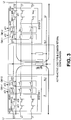
- Figure 3 illustrates a railway signaling system in accordance with the teachings of this invention wherein both controllers are active output controls commanding the load simultaneously.
- the example illustrated is a double-cut load (common return) control configuration.
- System 1 controls the load from the supply line (L1) through the disconnection relay (S1-KD-A1) a solid state relay (S1-SSR1-1) under S1-DDO-uC1 control, a solid state relay (S1-SSR1-2) under S1-DDO-uC2 control, disconnection relay (S1-KD-B1), current measuring for S1-DDO-uC1 (S1-CM1-1), current measuring for S1-DDO-uC2 (S1-CM1-2), load, to return line (L2).
- Supply line (L1) and return line (L2) can be either AC or DC supply.
- System 2 controls the load from the supply line (L1) through the disconnection relay (S2-KD-A1) a solid state relay (S2-SSR1-1) under S2-DDO-uC1 control, a solid state relay (S2-SSR1-2) under S2-DDO-uC2 control, disconnection relay (S2-KD-B1), current measuring for S2-DDO-uC1 (S2-CM1-1), current measuring for S2-DDO-uC2 (S2-CM1-2), load, to return line (L2).
- S2-KD-A1 solid state relay
- S2-SSR1-1 solid state relay
- S2-SSR1-2 solid state relay
- S2-KD-B1 disconnection relay
- current measuring for S2-DDO-uC1 S2-CM1-1
- S2-CM1-2 current measuring for S2-DDO-uC2
- load to return line (L2).
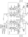
- FIG 4 illustrates a generic common load output circuit wherein both controllers are active.
- This generic output circuit is implemented as a series double cut configuration with Solid State Relay 5, 6 (SSR) control and a double cut configuration for circuit isolation 25, 30 (KD relays are FAR type).
- SSR Solid State Relay 5, 6
- KD relays are FAR type.
- Embodiments of the invention also contemplate latent failure detection test of reactive solid state hardware components.
- individual outputs contain SSR with Latent Failure Detection circuitry 10, 11 (one each controlled by each controller) for leakage on SSR circuits. The leakage detection is implemented when the SSRs 5, 6 are commanded OFF.
- Latent Failure Detection (LFD) test consists in activation of the LFD SSR10, 11 and series resistor (for example a LFD SSR 10 to test SSR B-1 6, and LFD SSR 11 to test SSR A-1 5) and measuring of the current 15, 16. The test is sequential, test one SSR at a time, and in case that there is no failure there will be no current detected.
- a test is implemented to validate the OFF state of the load by simulating leakage on both LFD SSRs 10, 11, commanding LFD A1-1 and LFD B1-1 simultaneously.
- the current through the load is limited by the LFD resistors which guarantee that the current cannot increase during test.
- the test to validate the OFF state of the load is performed every time when the LFD test is performed.
- the latent failure detection test has no effect on outputs which are commanded ON.
- the LFD test sequence is implemented on programmable devices (FPGAs).
- the start of LFD test is generated by the controllers (uCs) command to FPGAs.
- the output LFD timing is found in Figure 7 .
- signals OLFD_A(0) to OLFD_A(7) are generated by the FPGA1 to enable the LFD SSRs A1-1 to LFD_A8-1.
- Signals OLFD_B(0) to OLFD_B(7) are generated by the FPGA2 to enable the LFD SSRs B1-1 to LFD B8-1.
- Signals OUT_STATUS_(0) to OUT_STATUS_(7) are the result at the system level of the sequential commands from both FPGAs.
- FIG. 5 illustrates another implementation option of a railway system in accordance with the teachings of this invention.
- both controllers are on-line and the circuit is a common return loads output circuit.
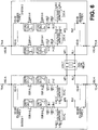
- FIG. 6 illustrates another implementation option of a railway system in accordance with the teachings of this invention.
- both controllers are on-line and the circuit is a dual coil relay control.
- embodiments of the invention can be installed at any suitable lineside location, such as the start of a section of track, at a junction, etc. or used in single or double tracks.
Landscapes
- Engineering & Computer Science (AREA)
- Mechanical Engineering (AREA)
- Train Traffic Observation, Control, And Security (AREA)
- Electric Propulsion And Braking For Vehicles (AREA)
Description
- The present invention relates to the rail industry. More specifically, the present invention relates to railway signaling systems.
- The rail industry, for both passenger and freight trains, is an important industry worldwide. Obviously the safety and reliability of train systems is crucial. Rail systems are particularly vulnerable to catastrophic accidents since trains travel on fixed tracks at speeds that prevent them from being able to stop quickly.
- Railway signaling systems are used to communicate a multitude of information to various railway personnel. Various types of trackside equipment (point/switch machine, signals, track circuits) are used along the track line. Trackside equipment can communicate different types of information, such as track status, required speeds, etc., all being crucial to preventing trains from colliding.
- The consequence of failure of trackside equipment can be disastrous. As such, current systems employ safety methods to mitigate failure or error. Regular maintenance of trackside equipment must also be taken into account.
- Generally, trackside equipment is managed by devices such as interlockings and zone controllers. Typically these controllers manage trackside field equipment through vital relay groups. In some cases, custom direct drive boards have been developed to interface with particular equipment types.
- Existing known solutions which manage dual outputs (redundant configuration for zone controllers) are controlled through an external hardware "OR" device, which is a single point of failure. Additionally, these design solutions are configured only as active- passive and thus manage a controlled switchover which interrupts the final condition.
US2006/269202A1 discloses a signalling system comprising two rendundant switched mode power supplies - Currently there is no redundant configuration solid state direct driver solution in the art of railway signaling systems which is free of a single point of failure to provide an active-active configuration for outputs connected to a common load. Embodiments of the present invention provide a safe solution for active-active redundant system which eliminates the switching time required by the active-passive system during the controlled switchover. Therefore there will be no interruption in the control and monitoring of the trackside equipment, eliminating the transitory periods (signals flashing or interlocking relays being wrongfully de-energized)
- Embodiments of the present invention also provide means of safe testing of one redundant system without affecting the safe functionality of the other system.
- Accordingly, disclosed is a railway signaling system comprised of a dedicated control circuit in an entirely redundant configuration (and thus with no single point of failure). Embodiments of the invention power dual outputs seamlessly, providing a continuous and unflinching electrical supply to a load to counteract output disruption during both scheduled maintenance and fail-over.
- The load in accordance with the teachings of this invention is any suitable trackside equipment (for example: signals) or interlocking relay used in railway signaling systems.
- Embodiments of the invention contemplate providing a redundant design, entirely free of single point of failures, such that a failure or planned maintenance activity in one resident partner of the system can be achieved without affecting system operations. In addition, the actual outputs are driven simultaneously between each hardware partner commanding a common load, reacting to failover/switchover without perturbation to outputs resulting in seamless redundancy.
- In accordance with the teachings of this invention, full system hardware redundancy is supported by using two independent controllers which command a load in active-active (where both controllers are on-line) configuration. With each controller active and healthy, the current through the load is shared between each system.
- It is envisaged that when one of the autonomous units detects a failure in functionality, that failed controller is disconnected and isolated from the working system while the live redundant controller continues to command the load seamlessly.
- Since embodiments of the invention are envisaged for use in railway signaling systems, various safety critical features are provided. These include continuous output current monitoring, voltage threshold detection, management of outputs, and means of load current supervision of dual "active-active" outputs at higher processing level.
- Thus, according to one aspect, the invention provides a railway signaling system for controlling a load, the system comprising a first autonomous controller with a first power output connectable to the load; a second autonomous controller which is redundant with the first controller such that there is no single point of failure, the second controller having a second power output connectable to the load; the first and second controllers operable in either an on-line mode wherein both power outputs provide power to the load or an off-line mode wherein a single power output does not provide power to the load; wherein the first and second controllers normally operate in the on-line mode to control the load such that current through the load is shared between the first and second controllers; wherein if one of the first or second controllers is operating off-line, the other controller continues to operate on-line to control the load, whereby control of the load is uninterrupted, characterised in that, when both controllers are on-line, the current provided by each controller is above a lower threshold limit and below an upper threshold limit, and if one controller provides current above the upper threshold limit or below the lower threshold limit, then that controller will go off-line.
- Thus, according to one aspect, the invention provides a method of controlling a load in a railway signaling system, the method comprising providing a first autonomous controller connectable to the load and a second autonomous controller which is redundant with the first controller such that there is no single point of failure; operating the first and second controllers in either: an on-line mode wherein both controllers provide power to the load to control the load such that current through the load is shared between the first and second controllers; or in an off-line mode wherein a single controller does not provide power to the load and the other controller continues to operate on-line to control the load, whereby control of the load is uninterrupted; monitoring current through each of the first and second controllers if both the first and second controllers are on-line; wherein when both controllers are on-line, the current provided by each controller is above a lower threshold limit and below an upper threshold limit, the method further comprising switching one controller to the off-line mode if that controller provides current above the upper threshold limit or below the lower threshold limit.
- Embodiments of this invention are designed based on CENEC EN-50129 and AREMA
Part 16 and 17 standards and industry standard principles. - Other aspects and advantages of embodiments of the invention will be readily apparent to those ordinarily skilled in the art upon a review of the following description.
- Embodiments of the invention will now be described in conjunction with the accompanying drawings, wherein:
-
Figure 1 illustrates a top level schematic of a railway signaling system in accordance with the teachings of this invention; -
Figure 2 illustrates circuitry of a railway signaling system in accordance with the teachings of this invention wherein both controllers are active output controls commanding the load simultaneously (load being controlled in double-cut configuration when both supply and return lines are controlled by the redundant system); -
Figure 3 illustrates a railway signaling system in accordance with the teachings of this invention wherein both controllers are active output controls commanding the load simultaneously (load being controlled in common return configuration when only supply line is controlled by the redundant system); -
Figure 4 illustrates a detailed configuration of the direct drive output with generic common load output circuit, wherein both controllers are active; -
Figure 5 illustrates another implementation option of a railway system in accordance with the teachings of this invention; -
Figure 6 illustrates another implementation option of a railway system in accordance with the teachings of this invention; and -
Figure 7 illustrated the output of latent failure detection test as can be implemented in accordance with the teachings of this invention. - This invention will now be described in detail with respect to certain specific representative embodiments thereof, the materials, apparatus and process steps being understood as examples that are intended to be illustrative only. In particular, the invention is not intended to be limited to the methods, materials, conditions, process parameters, apparatus and the like specifically recited herein.
- Referring to
Figure 1 , there is illustrated a top level schematic drawing of a railway signaling system in accordance with the teachings of this invention. Thecomplete system 10 comprisesSystem 1 andSystem 2 having a first and a second controller, MPU1 and MPU2. Each controller, MPU1 and MPU2, has multiple direct drive outputs (designated asDDO 1...n), a power bus and output ,OUTn, in communication with the load(s). Each controller MPU1 and MPU2 is independent of the other and is completely redundant. In this way, thesystem 10 is free of any single point of failure. Further details will be discussed below. - Both controllers MPU1 and MPU2 use the same power supply, though each is protected by individual circuit breakers. This common power supply can be either AC or DC source. The DC power source for the outputs is represented in
Figure 4 (PSU-A1, PSU-A2) The AC power source for the outputs is presented inFigure 5 (TB, TC) - Referring back to
Figure 1 , each controller, MPU1 and MPU2, is operable in either an on-line mode or an off-line mode. On-line mode means the controller is "on" to control the load(s); off-line means the controller is "off' and is not controlling the load(s). Within thesystem 10, both controllers MPU1 and MPU2 can be on-line or one controller can be on-line with one controller being off-line. A controller can be off-line either due to a failure in operation or due to a planned maintenance. - The load (there could be more than one) in accordance with the teachings of this invention is any suitable physical signal used in railway signaling systems. For example, the load could be a light system to communicate various information to a train conductor.
- The system is designed to react in specific actions based on the operation of the controllers.
- If both controllers on on-line, the both controllers provide power via respective outputs, DDO, to the load. In such an active-active mode (where both controllers are on-line), the current through the load is shared by the two controllers. The imbalance of current sharing between the two redundant systems is allowed up to a threshold limit. If the threshold limit is exceeded by one system, that system will declare a failure and isolate from the load, thus the redundant system will control solely the load. Each DDO is composed out of two microcontrollers (uC) in a 2oo2 configuration (uC-A and uC-B), and the specific functional circuits to provide the interface to external elements.
- Referring back to
Figure 4 , it can be seen that each microcontroller has a respectivecurrent monitoring circuit - In order to correctly determine the load status, each controller (
MPU 1 and MPU2) monitors if the load is shared or not (information available based on communication path between the two systems) and also the configuration of the load. It should be noted that there could be multiple loads connected in parallel, controlled with a single output from each controller as illustrated inFigure 1 . This information is part of the system database available at the MPU1 and MPU2 level. The output of each current monitoring circuit is proportional with the current through the outputs and the load. Statuses are independently provided to each uC for each output. - The current is monitored continuously. In order to validate the current measurement, there are two threshold references: for minimum load (preferably: 10% of nominal current) and nominal load (preferably: 75% of nominal current). The two threshold references are common for both controllers. These references are used to characterize the A/D conversion parameters for each controller.
- In case of threshold failure (based on exceeding the tolerance of reference readings from each controller) the system will declare a failure and it will isolate itself from the load.
- Each DDO also has a
disconnection mechanism 25, 30 (isolation from load). The disconnection mechanism (illustrated inFigure 4 as relay contacts KD-A1 (25) to KD-A8 and relay contacts KD-B1 (30) to KD-B8) is used to disconnect an off-line controller's output from the load. To correctly identify the status of disconnection mechanism, the relays conform with EN50205 typeA requirements. Preferably, when an independent unit fails or goes off-line, disconnection of its outputs is also guaranteed by means of anexternal hardware shutdown 1 which isAREMA Class 1 compliant. The hardware shutdown mechanism can be any suitable mechanism. Preferably this vital disconnect is implemented through Association of American Railway (AAR) vital relays. - Embodiments of the invention ensure that when one of the autonomous controllers MPU1 and MPU2 fail or goes off-line, the remaining on-line controller continuously monitors that no failure of the off-line controller will compromise safe system operations. In particular, it can be seen from
Figure 4 that each output further comprises avoltage monitoring circuit 20. The controller shut off and/or off-line status, will prompt the following additional supervisions by the remaining on-line unit. The output voltage of every individual output of on-line controllers is monitored to ascertain that the voltage is zero when the individual output is commanded off. -
Figure 2 illustrates circuitry of a railway signaling system in accordance with the teachings of this invention wherein both controllers (system 1 and system 2) are active output controls commanding the load simultaneously. The example illustrated is a double-cut load (individual return) control configuration. -
System 1 controls the load from the supply line (L1) through the disconnection relay (S1-KD-A1) a solid state relay (S1-SSR1-1) under S1-DDO-uC1 control, a solid state relay (S1-SSR1-2) under S1-DDO-uC2 control, current measuring for S1-DDO-uC1 (S1-CM1-1), current measuring for S1-DDO-uC2 (S1-CM1-2), load, disconnection relay (S1-KD-B1) to return line (L2). - Supply line (L1) and return line (L2) can be either AC or DC supply.
-
System 2 controls the load from the supply line (L1) through the disconnection relay (S2-KD-A1) a solid state relay (S2-SSR1-1) under S2-DDO-uC1 control, a solid state relay (S2-SSR1-2) under S2-DDO-uC2 control, current measuring for S2-DDO-uC1 (S2-CM1-1), current measuring for S2-DDO-uC2 (S2-CM1-2), load, disconnection relay (S2-KD-B1) to return line (L2). Under normal conditions the current through load is equally shared between the two systems. -
Figure 3 illustrates a railway signaling system in accordance with the teachings of this invention wherein both controllers are active output controls commanding the load simultaneously. The example illustrated is a double-cut load (common return) control configuration. -
System 1 controls the load from the supply line (L1) through the disconnection relay (S1-KD-A1) a solid state relay (S1-SSR1-1) under S1-DDO-uC1 control, a solid state relay (S1-SSR1-2) under S1-DDO-uC2 control, disconnection relay (S1-KD-B1), current measuring for S1-DDO-uC1 (S1-CM1-1), current measuring for S1-DDO-uC2 (S1-CM1-2), load, to return line (L2). - Supply line (L1) and return line (L2) can be either AC or DC supply.
-
System 2 controls the load from the supply line (L1) through the disconnection relay (S2-KD-A1) a solid state relay (S2-SSR1-1) under S2-DDO-uC1 control, a solid state relay (S2-SSR1-2) under S2-DDO-uC2 control, disconnection relay (S2-KD-B1), current measuring for S2-DDO-uC1 (S2-CM1-1), current measuring for S2-DDO-uC2 (S2-CM1-2), load, to return line (L2). - Under normal conditions the current through load is equally shared between the two systems.
-
Figure 4 illustrates a generic common load output circuit wherein both controllers are active. This generic output circuit is implemented as a series double cut configuration withSolid State Relay 5, 6 (SSR) control and a double cut configuration forcircuit isolation 25, 30 (KD relays are FAR type). - Embodiments of the invention also contemplate latent failure detection test of reactive solid state hardware components. Referring to
Figure 4 , individual outputs contain SSR with LatentFailure Detection circuitry 10, 11 (one each controlled by each controller) for leakage on SSR circuits. The leakage detection is implemented when theSSRs LFD SSR 10 to test SSR B-1 6, andLFD SSR 11 to test SSR A-1 5) and measuring of the current 15, 16. The test is sequential, test one SSR at a time, and in case that there is no failure there will be no current detected. - A test is implemented to validate the OFF state of the load by simulating leakage on both
LFD SSRs - The latent failure detection test has no effect on outputs which are commanded ON. The LFD test sequence is implemented on programmable devices (FPGAs). The start of LFD test is generated by the controllers (uCs) command to FPGAs. The output LFD timing is found in
Figure 7 . -
- 1. Start of LFD test is provided by one uC by for duration of tSW (OLFD_START in the drawing below).
- 2. The programmable devices will provide a synchronization signal (OTOV in the drawing below). The synchronization signal provides information regarding the LFD testing step, which will trigger the uC to read the current status.
- 3. A delay (tSL) is implemented in the FPGA in order to validate the OLFD_START signal from uC (provide a digital filtering for noise).
- 4. Each uC reads the status of output current sequential (OUT_STATUS_(0) to OUT_STATUS_(7))
- Referring to
Figure 7 , signals OLFD_A(0) to OLFD_A(7) are generated by the FPGA1 to enable the LFD SSRs A1-1 to LFD_A8-1. - Signals OLFD_B(0) to OLFD_B(7) are generated by the FPGA2 to enable the LFD SSRs B1-1 to LFD B8-1.
- Signals OUT_STATUS_(0) to OUT_STATUS_(7) are the result at the system level of the sequential commands from both FPGAs.
-
Figure 5 illustrates another implementation option of a railway system in accordance with the teachings of this invention. In this example, both controllers are on-line and the circuit is a common return loads output circuit. -
Figure 6 illustrates another implementation option of a railway system in accordance with the teachings of this invention. In this example, both controllers are on-line and the circuit is a dual coil relay control. - It should be understood that embodiments of the invention can be installed at any suitable lineside location, such as the start of a section of track, at a junction, etc. or used in single or double tracks.
- Numerous modifications may be made without departing from the scope of the invention as defined in the appended claims.
Claims (11)
- A railway signaling system (10) for controlling a load (LOAD1), the system comprising:a first autonomous controller (MPU1) with a first power output (DDO1) connectable to the load;a second autonomous controller (MPU2) which is redundant with the first controller such that there is no single point of failure, the second controller having a second power output (DDO1) connectable to the load;the first and second controllers are each operable in either an on-line mode wherein the respective controller controls the load or an off-line mode wherein the respective controller does not control the load and the respective power output of the controller does not provide power to the load;wherein the first and second controllers are configured such that they normally both operate in the on-line mode to control the load such that current through the load is shared between the first and second controllers;wherein if one of the first or second controllers is operating off-line, the other controller is configured to continue to operate on-line to control the load, whereby control of the load is uninterrupted;characterised in that, when both controllers are on-line, the current provided by each controller is above a lower threshold limit and below an upper threshold limit, and if one controller provides current above the upper threshold limit or below the lower threshold limit, then that controller is configured to go off-line.
- The railway signaling system of claim 1, the first controller comprising a first current monitoring mechanism and the second controller comprising a second current monitoring mechanism, configured such that:
if both the first and second controllers are on-line, the first controller current monitoring mechanism monitors the current through the first power output and the second controller current monitoring mechanism monitors current through the second power output. - The railway signaling system of claim 1, the first controller comprising a first voltage monitoring mechanism and the second controller comprising a second voltage monitoring mechanism, wherein: if the first controller is off-line and the second controller is on-line, the second voltage monitoring mechanism monitors an output voltage of the power output of the second controller to ascertain that the output voltage is zero when the power output of the second controller is controlled to not provide power to the load.
- The railway signaling system of claim 1, wherein each of the first and second controllers comprises a disconnection mechanism to disconnect its respective controller from the load in the off-line mode.
- The railway signaling system of claim 4, wherein each disconnection mechanism comprises AAR vital relays.
- The railway signaling system of claim 1, wherein the first and second controllers are powered by a single power source, which is either AC or DC.
- The railway signaling system of claim 1, wherein the load is a physical signal located lineside along a train track.
- The railway signaling system of claim 1, wherein the off-line mode occurs either due to a failure or due to maintenance.
- A method of controlling a load (LOAD1) in a railway signaling system, the method comprising:providing a first autonomous controller (MPU1) connectable to the load and a second autonomous controller (MPU2) which is redundant with the first controller such that there is no single point of failure, wherein the first and second controllers are each operable in either an on-line mode wherein the respective controller controls the load or an off-line mode wherein the respective controller does not control the load and the respective power output (DDO1) of the controller does not provide power to the load;operating the first and second controllers either:with both the first and second controller in the on-line mode to control providing power to the load such that current through the load is shared between the first and second controllers;or with one of the first and second controllers in an off-line mode wherein that controller does not provide power to the load and the other controller continues to operate on-line to control the load, whereby control of the load is uninterrupted;monitoring current through each of the first and second controllers if both the first and second controllers are on-line;wherein when both controllers are on-line, the current provided by each controller is above a lower threshold limit and below an upper threshold limit, the method further comprising switching one controller to the off-line mode if that controller provides current above the upper threshold limit or below the lower threshold limit.
- The method of claim 9, wherein if the first controller is off-line and the second controller is on-line, the second controller monitors an output voltages of a power output of the second controller to ascertain that the output voltage is zero when the power output of the second controller is controlled to not provide power to the load.
- The method of claim 10, further comprising disconnecting a controller if it is in the offline mode.
Applications Claiming Priority (2)
| Application Number | Priority Date | Filing Date | Title |
|---|---|---|---|
| US13/169,160 US8668170B2 (en) | 2011-06-27 | 2011-06-27 | Railway signaling system with redundant controllers |
| PCT/CA2012/000607 WO2013000063A1 (en) | 2011-06-27 | 2012-06-21 | Railway signaling system with redundant controllers |
Publications (3)
| Publication Number | Publication Date |
|---|---|
| EP2723623A1 EP2723623A1 (en) | 2014-04-30 |
| EP2723623A4 EP2723623A4 (en) | 2015-12-09 |
| EP2723623B1 true EP2723623B1 (en) | 2019-11-13 |
Family
ID=47360927
Family Applications (1)
| Application Number | Title | Priority Date | Filing Date |
|---|---|---|---|
| EP12804670.3A Active EP2723623B1 (en) | 2011-06-27 | 2012-06-21 | Railway signaling system with redundant controllers |
Country Status (9)
| Country | Link |
|---|---|
| US (2) | US8668170B2 (en) |
| EP (1) | EP2723623B1 (en) |
| JP (1) | JP5996642B2 (en) |
| KR (1) | KR20140039235A (en) |
| CN (1) | CN103764480A (en) |
| BR (1) | BR112013032959A2 (en) |
| CA (1) | CA2837645C (en) |
| MY (1) | MY159476A (en) |
| WO (1) | WO2013000063A1 (en) |
Cited By (1)
| Publication number | Priority date | Publication date | Assignee | Title |
|---|---|---|---|---|
| EP4480781A1 (en) * | 2023-06-19 | 2024-12-25 | Siemens Mobility GmbH | Railway track system with interface device and method for its operation |
Families Citing this family (24)
| Publication number | Priority date | Publication date | Assignee | Title |
|---|---|---|---|---|
| JP6296673B2 (en) * | 2011-09-30 | 2018-03-20 | 日本信号株式会社 | Train control system ground equipment |
| JP5898904B2 (en) * | 2011-09-30 | 2016-04-06 | 日本信号株式会社 | Train control system |
| JP5858711B2 (en) * | 2011-09-30 | 2016-02-10 | 日本信号株式会社 | On-board equipment for train control systems |
| DE102012221972A1 (en) * | 2012-11-30 | 2014-06-18 | Siemens Aktiengesellschaft | Circuit arrangement for error disclosure in a light signal |
| CN103246266B (en) * | 2013-04-26 | 2015-04-29 | 王为学 | Industrial online maintenance-free control system |
| US11814088B2 (en) * | 2013-09-03 | 2023-11-14 | Metrom Rail, Llc | Vehicle host interface module (vHIM) based braking solutions |
| JP6145019B2 (en) * | 2013-10-08 | 2017-06-07 | 公益財団法人鉄道総合技術研究所 | Fault display device for dual system |
| US9618909B2 (en) * | 2013-12-20 | 2017-04-11 | Thales Canada Inc | Safety assurance of multiple redundant systems |
| CN104890701B (en) * | 2015-06-26 | 2017-01-18 | 杭州路信科技有限公司 | Railway station communication linkage system |
| WO2017008710A1 (en) * | 2015-07-10 | 2017-01-19 | 海能达通信股份有限公司 | Rail transit scheduling method, server and system |
| US10332708B2 (en) | 2015-12-09 | 2019-06-25 | Thales Canada Inc | Seamless switchover system and method |
| DE102016205119A1 (en) * | 2016-03-29 | 2017-10-05 | Siemens Aktiengesellschaft | System for controlling signal boxes in rail traffic |
| FR3054687B1 (en) * | 2016-07-28 | 2019-05-17 | Airbus (S.A.S.) | DEVICE AND METHOD FOR DISPLAYING A DOCUMENT |
| CN107031684A (en) * | 2016-11-14 | 2017-08-11 | 中国铁路总公司 | A kind of two-shipper Safety Redundancy type LKJ host computer systems and method |
| CN109305190A (en) * | 2017-07-28 | 2019-02-05 | 比亚迪股份有限公司 | Switch control system, method and switch controller |
| CN107933613B (en) * | 2017-11-27 | 2020-05-12 | 卡斯柯信号有限公司 | Non-national standard turnout driving system based on two-by-two architecture |
| CN109541987B (en) * | 2018-10-17 | 2021-09-03 | 同济大学 | Plug-and-play intelligent automobile domain controller with redundancy structure and method |
| CN111169506A (en) * | 2018-11-13 | 2020-05-19 | 比亚迪股份有限公司 | Switch control system and switch logic control module |
| CN109677454B (en) * | 2018-11-23 | 2020-11-10 | 交控科技股份有限公司 | State monitoring method for safety computer platform in urban rail transit signal system |
| CN110554978B (en) * | 2019-08-30 | 2022-02-15 | 北京交大思诺科技股份有限公司 | Safety computer platform realized by universal I/O module |
| EP4028301A4 (en) * | 2019-09-12 | 2023-11-08 | Thales Canada Inc. | SURGE PROTECTION DEVICE |
| CN110979404B (en) * | 2019-12-19 | 2021-11-12 | 交控科技股份有限公司 | Dual-machine hot standby system and method of automatic train supervision system |
| RU200885U1 (en) * | 2020-03-02 | 2020-11-17 | Бомбардье Транспортейшн Гмбх | Railway objects controller |
| CN120270298B (en) * | 2025-05-07 | 2026-01-27 | 兰州交通大学 | Switch machine based on control of double-machine hot standby servo motor and control method |
Family Cites Families (22)
| Publication number | Priority date | Publication date | Assignee | Title |
|---|---|---|---|---|
| EP0472747B1 (en) | 1990-08-21 | 1994-02-23 | Scheidt & Bachmann Gmbh | Arrangement for the supervised operation of a consumer |
| US7539624B2 (en) * | 1994-09-01 | 2009-05-26 | Harris Corporation | Automatic train control system and method |
| JP3820322B2 (en) | 1998-11-30 | 2006-09-13 | 株式会社日立製作所 | Equipment-distributed electronic interlocking device |
| US6556898B2 (en) * | 2001-05-18 | 2003-04-29 | Bombardier Transportation Gmbh | Distributed track network control system |
| JP4095413B2 (en) | 2002-11-26 | 2008-06-04 | 三菱電機株式会社 | Electronic interlocking device |
| US7297731B2 (en) | 2003-03-11 | 2007-11-20 | 3M Innovative Properties Company | Coating dispersions for optical fibers |
| US7140577B2 (en) * | 2004-04-08 | 2006-11-28 | General Electric Company | Remote system for monitoring and controlling railroad wayside equipment |
| US7577502B1 (en) * | 2004-07-08 | 2009-08-18 | J & A Industries, Inc. | Proximity detection and communication mechanism and method |
| JP2006086654A (en) * | 2004-09-14 | 2006-03-30 | Canon Inc | Imaging device |
| US20060259202A1 (en) * | 2005-01-24 | 2006-11-16 | Vaish Himangshu R | Signaling system |
| CN100519293C (en) * | 2005-12-19 | 2009-07-29 | 北京交通大学 | Wireless locomotive signal dual-engine warm standby control method |
| CN1986314B (en) * | 2005-12-22 | 2012-07-25 | 株式会社日立制作所 | Signaling vigilance system |
| ATE460325T1 (en) * | 2006-03-29 | 2010-03-15 | Tiefenbach Gmbh | DEVICE FOR CONNECTING AND MONITORING A LIGHT SIGNAL SYSTEM IN RAILWAY TRAFFIC |
| EP2125482B1 (en) | 2006-12-22 | 2014-05-14 | Central Signal, LLC | Vital solid state controller |
| US8028961B2 (en) * | 2006-12-22 | 2011-10-04 | Central Signal, Llc | Vital solid state controller |
| US8214092B2 (en) * | 2007-11-30 | 2012-07-03 | Siemens Industry, Inc. | Method and apparatus for an interlocking control device |
| JP4762300B2 (en) * | 2008-12-12 | 2011-08-31 | 株式会社京三製作所 | Traffic light control system |
| CN101486349B (en) * | 2009-02-26 | 2011-02-09 | 温应群 | Double computer hot standby automatic passing neutral section device |
| US8338988B2 (en) * | 2009-04-17 | 2012-12-25 | Lsi Corporation | Adaptation of an active power supply set using an event trigger |
| US20110006167A1 (en) * | 2009-07-07 | 2011-01-13 | Ron Tolmei | Fail-safe safety system to detect and annunciate fractured running rails in electrically propelled transit systems |
| US8515697B2 (en) * | 2010-05-06 | 2013-08-20 | Ansaldo Sts Usa, Inc. | Apparatus and method for vital signal state detection in overlay rail signal monitoring |
| WO2012075401A1 (en) * | 2010-12-03 | 2012-06-07 | Metrom Rail, Llc | Rail line sensing and safety system |
-
2011
- 2011-06-27 US US13/169,160 patent/US8668170B2/en active Active
-
2012
- 2012-06-21 CA CA2837645A patent/CA2837645C/en active Active
- 2012-06-21 KR KR1020137034293A patent/KR20140039235A/en not_active Ceased
- 2012-06-21 CN CN201280031711.4A patent/CN103764480A/en active Pending
- 2012-06-21 EP EP12804670.3A patent/EP2723623B1/en active Active
- 2012-06-21 MY MYPI2013004602A patent/MY159476A/en unknown
- 2012-06-21 WO PCT/CA2012/000607 patent/WO2013000063A1/en not_active Ceased
- 2012-06-21 JP JP2014517349A patent/JP5996642B2/en active Active
- 2012-06-21 BR BR112013032959A patent/BR112013032959A2/en not_active IP Right Cessation
-
2014
- 2014-01-23 US US14/162,674 patent/US9096245B2/en active Active
Non-Patent Citations (1)
| Title |
|---|
| None * |
Cited By (1)
| Publication number | Priority date | Publication date | Assignee | Title |
|---|---|---|---|---|
| EP4480781A1 (en) * | 2023-06-19 | 2024-12-25 | Siemens Mobility GmbH | Railway track system with interface device and method for its operation |
Also Published As
| Publication number | Publication date |
|---|---|
| MY159476A (en) | 2017-01-13 |
| JP5996642B2 (en) | 2016-09-21 |
| US8668170B2 (en) | 2014-03-11 |
| EP2723623A1 (en) | 2014-04-30 |
| CN103764480A (en) | 2014-04-30 |
| BR112013032959A2 (en) | 2017-01-24 |
| US20120325981A1 (en) | 2012-12-27 |
| CA2837645A1 (en) | 2013-01-03 |
| CA2837645C (en) | 2017-04-25 |
| WO2013000063A1 (en) | 2013-01-03 |
| KR20140039235A (en) | 2014-04-01 |
| JP2014518173A (en) | 2014-07-28 |
| US9096245B2 (en) | 2015-08-04 |
| EP2723623A4 (en) | 2015-12-09 |
| US20140138495A1 (en) | 2014-05-22 |
Similar Documents
| Publication | Publication Date | Title |
|---|---|---|
| CA2837645C (en) | Railway signaling system with redundant controllers | |
| US8620497B2 (en) | Computer interlocking system and code bit level redundancy method therefor | |
| KR101340080B1 (en) | Control apparatus for automatic switch to main information process module in train control system | |
| JP2010220465A (en) | Electrical power distribution | |
| US11661313B2 (en) | Drive device having safety circuits using logic states for an elevator | |
| CN101700783B (en) | Train control center system platform | |
| KR101210930B1 (en) | Control apparatus for automatic switch of trackside signal processing modules in railroad | |
| CN103389668A (en) | Hot standby redundancy central control panel used for screen door | |
| KR20160081575A (en) | Dual apparatus for controller | |
| CN111186463A (en) | Board-level redundant full-electronic computer interlocking system | |
| CN113665368B (en) | A redundant fault-tolerant control system for the suspension frame of EMS high-speed maglev trains | |
| KR101764680B1 (en) | Redundancy control system | |
| HK1195288A (en) | Railway signaling system with redundant controllers | |
| HK1195288B (en) | Railway signaling system with redundant controllers | |
| US9038965B2 (en) | Method and sequential monitoring overlay system for track circuits | |
| KR101568904B1 (en) | System and method for controlling train | |
| KR100673535B1 (en) | Transfer system and method by multiplexing information processing module of train track side | |
| CN104901839A (en) | CRH (China Railway High-Speed) main processor (MPU) redundancy method | |
| CN107919725B (en) | Aviation power supply control box adopting staggered control configuration | |
| CN113401169A (en) | Control method, device and system based on signal lamp control circuit | |
| KR100512303B1 (en) | Fault tolerant-fail safe control system for ns type pointer | |
| EP3118052A1 (en) | Train information management device | |
| CN120922199A (en) | Track circuit monitoring device, method, equipment and program product | |
| CN102684916A (en) | Redundant communication object control method in comprehensive monitoring system for passenger special line | |
| MX2012004516A (en) | System for the remote reactivation and monitoring of an electronic cabinet for controlling the operation of trains. |
Legal Events
| Date | Code | Title | Description |
|---|---|---|---|
| PUAI | Public reference made under article 153(3) epc to a published international application that has entered the european phase |
Free format text: ORIGINAL CODE: 0009012 |
|
| 17P | Request for examination filed |
Effective date: 20140102 |
|
| AK | Designated contracting states |
Kind code of ref document: A1 Designated state(s): AL AT BE BG CH CY CZ DE DK EE ES FI FR GB GR HR HU IE IS IT LI LT LU LV MC MK MT NL NO PL PT RO RS SE SI SK SM TR |
|
| DAX | Request for extension of the european patent (deleted) | ||
| REG | Reference to a national code |
Ref country code: HK Ref legal event code: DE Ref document number: 1195288 Country of ref document: HK |
|
| RA4 | Supplementary search report drawn up and despatched (corrected) |
Effective date: 20151106 |
|
| RIC1 | Information provided on ipc code assigned before grant |
Ipc: B61L 27/00 20060101ALI20151102BHEP Ipc: B61L 7/08 20060101AFI20151102BHEP Ipc: B61L 5/18 20060101ALI20151102BHEP Ipc: B61L 23/00 20060101ALI20151102BHEP |
|
| STAA | Information on the status of an ep patent application or granted ep patent |
Free format text: STATUS: EXAMINATION IS IN PROGRESS |
|
| 17Q | First examination report despatched |
Effective date: 20170524 |
|
| GRAP | Despatch of communication of intention to grant a patent |
Free format text: ORIGINAL CODE: EPIDOSNIGR1 |
|
| STAA | Information on the status of an ep patent application or granted ep patent |
Free format text: STATUS: GRANT OF PATENT IS INTENDED |
|
| INTG | Intention to grant announced |
Effective date: 20190531 |
|
| GRAS | Grant fee paid |
Free format text: ORIGINAL CODE: EPIDOSNIGR3 |
|
| GRAA | (expected) grant |
Free format text: ORIGINAL CODE: 0009210 |
|
| STAA | Information on the status of an ep patent application or granted ep patent |
Free format text: STATUS: THE PATENT HAS BEEN GRANTED |
|
| AK | Designated contracting states |
Kind code of ref document: B1 Designated state(s): AL AT BE BG CH CY CZ DE DK EE ES FI FR GB GR HR HU IE IS IT LI LT LU LV MC MK MT NL NO PL PT RO RS SE SI SK SM TR |
|
| REG | Reference to a national code |
Ref country code: CH Ref legal event code: EP Ref country code: AT Ref legal event code: REF Ref document number: 1201367 Country of ref document: AT Kind code of ref document: T Effective date: 20191115 |
|
| REG | Reference to a national code |
Ref country code: DE Ref legal event code: R096 Ref document number: 602012065690 Country of ref document: DE |
|
| REG | Reference to a national code |
Ref country code: IE Ref legal event code: FG4D |
|
| REG | Reference to a national code |
Ref country code: NL Ref legal event code: MP Effective date: 20191113 |
|
| REG | Reference to a national code |
Ref country code: LT Ref legal event code: MG4D |
|
| PG25 | Lapsed in a contracting state [announced via postgrant information from national office to epo] |
Ref country code: ES Free format text: LAPSE BECAUSE OF FAILURE TO SUBMIT A TRANSLATION OF THE DESCRIPTION OR TO PAY THE FEE WITHIN THE PRESCRIBED TIME-LIMIT Effective date: 20191113 Ref country code: PL Free format text: LAPSE BECAUSE OF FAILURE TO SUBMIT A TRANSLATION OF THE DESCRIPTION OR TO PAY THE FEE WITHIN THE PRESCRIBED TIME-LIMIT Effective date: 20191113 Ref country code: SE Free format text: LAPSE BECAUSE OF FAILURE TO SUBMIT A TRANSLATION OF THE DESCRIPTION OR TO PAY THE FEE WITHIN THE PRESCRIBED TIME-LIMIT Effective date: 20191113 Ref country code: NO Free format text: LAPSE BECAUSE OF FAILURE TO SUBMIT A TRANSLATION OF THE DESCRIPTION OR TO PAY THE FEE WITHIN THE PRESCRIBED TIME-LIMIT Effective date: 20200213 Ref country code: LV Free format text: LAPSE BECAUSE OF FAILURE TO SUBMIT A TRANSLATION OF THE DESCRIPTION OR TO PAY THE FEE WITHIN THE PRESCRIBED TIME-LIMIT Effective date: 20191113 Ref country code: PT Free format text: LAPSE BECAUSE OF FAILURE TO SUBMIT A TRANSLATION OF THE DESCRIPTION OR TO PAY THE FEE WITHIN THE PRESCRIBED TIME-LIMIT Effective date: 20200313 Ref country code: FI Free format text: LAPSE BECAUSE OF FAILURE TO SUBMIT A TRANSLATION OF THE DESCRIPTION OR TO PAY THE FEE WITHIN THE PRESCRIBED TIME-LIMIT Effective date: 20191113 Ref country code: BG Free format text: LAPSE BECAUSE OF FAILURE TO SUBMIT A TRANSLATION OF THE DESCRIPTION OR TO PAY THE FEE WITHIN THE PRESCRIBED TIME-LIMIT Effective date: 20200213 Ref country code: GR Free format text: LAPSE BECAUSE OF FAILURE TO SUBMIT A TRANSLATION OF THE DESCRIPTION OR TO PAY THE FEE WITHIN THE PRESCRIBED TIME-LIMIT Effective date: 20200214 Ref country code: LT Free format text: LAPSE BECAUSE OF FAILURE TO SUBMIT A TRANSLATION OF THE DESCRIPTION OR TO PAY THE FEE WITHIN THE PRESCRIBED TIME-LIMIT Effective date: 20191113 Ref country code: NL Free format text: LAPSE BECAUSE OF FAILURE TO SUBMIT A TRANSLATION OF THE DESCRIPTION OR TO PAY THE FEE WITHIN THE PRESCRIBED TIME-LIMIT Effective date: 20191113 |
|
| PG25 | Lapsed in a contracting state [announced via postgrant information from national office to epo] |
Ref country code: HR Free format text: LAPSE BECAUSE OF FAILURE TO SUBMIT A TRANSLATION OF THE DESCRIPTION OR TO PAY THE FEE WITHIN THE PRESCRIBED TIME-LIMIT Effective date: 20191113 Ref country code: RS Free format text: LAPSE BECAUSE OF FAILURE TO SUBMIT A TRANSLATION OF THE DESCRIPTION OR TO PAY THE FEE WITHIN THE PRESCRIBED TIME-LIMIT Effective date: 20191113 Ref country code: IS Free format text: LAPSE BECAUSE OF FAILURE TO SUBMIT A TRANSLATION OF THE DESCRIPTION OR TO PAY THE FEE WITHIN THE PRESCRIBED TIME-LIMIT Effective date: 20200313 |
|
| PG25 | Lapsed in a contracting state [announced via postgrant information from national office to epo] |
Ref country code: AL Free format text: LAPSE BECAUSE OF FAILURE TO SUBMIT A TRANSLATION OF THE DESCRIPTION OR TO PAY THE FEE WITHIN THE PRESCRIBED TIME-LIMIT Effective date: 20191113 |
|
| PG25 | Lapsed in a contracting state [announced via postgrant information from national office to epo] |
Ref country code: RO Free format text: LAPSE BECAUSE OF FAILURE TO SUBMIT A TRANSLATION OF THE DESCRIPTION OR TO PAY THE FEE WITHIN THE PRESCRIBED TIME-LIMIT Effective date: 20191113 Ref country code: CZ Free format text: LAPSE BECAUSE OF FAILURE TO SUBMIT A TRANSLATION OF THE DESCRIPTION OR TO PAY THE FEE WITHIN THE PRESCRIBED TIME-LIMIT Effective date: 20191113 Ref country code: EE Free format text: LAPSE BECAUSE OF FAILURE TO SUBMIT A TRANSLATION OF THE DESCRIPTION OR TO PAY THE FEE WITHIN THE PRESCRIBED TIME-LIMIT Effective date: 20191113 Ref country code: DK Free format text: LAPSE BECAUSE OF FAILURE TO SUBMIT A TRANSLATION OF THE DESCRIPTION OR TO PAY THE FEE WITHIN THE PRESCRIBED TIME-LIMIT Effective date: 20191113 |
|
| REG | Reference to a national code |
Ref country code: DE Ref legal event code: R097 Ref document number: 602012065690 Country of ref document: DE |
|
| REG | Reference to a national code |
Ref country code: AT Ref legal event code: MK05 Ref document number: 1201367 Country of ref document: AT Kind code of ref document: T Effective date: 20191113 |
|
| PG25 | Lapsed in a contracting state [announced via postgrant information from national office to epo] |
Ref country code: SK Free format text: LAPSE BECAUSE OF FAILURE TO SUBMIT A TRANSLATION OF THE DESCRIPTION OR TO PAY THE FEE WITHIN THE PRESCRIBED TIME-LIMIT Effective date: 20191113 Ref country code: SM Free format text: LAPSE BECAUSE OF FAILURE TO SUBMIT A TRANSLATION OF THE DESCRIPTION OR TO PAY THE FEE WITHIN THE PRESCRIBED TIME-LIMIT Effective date: 20191113 |
|
| PLBE | No opposition filed within time limit |
Free format text: ORIGINAL CODE: 0009261 |
|
| STAA | Information on the status of an ep patent application or granted ep patent |
Free format text: STATUS: NO OPPOSITION FILED WITHIN TIME LIMIT |
|
| 26N | No opposition filed |
Effective date: 20200814 |
|
| PG25 | Lapsed in a contracting state [announced via postgrant information from national office to epo] |
Ref country code: SI Free format text: LAPSE BECAUSE OF FAILURE TO SUBMIT A TRANSLATION OF THE DESCRIPTION OR TO PAY THE FEE WITHIN THE PRESCRIBED TIME-LIMIT Effective date: 20191113 Ref country code: AT Free format text: LAPSE BECAUSE OF FAILURE TO SUBMIT A TRANSLATION OF THE DESCRIPTION OR TO PAY THE FEE WITHIN THE PRESCRIBED TIME-LIMIT Effective date: 20191113 |
|
| PG25 | Lapsed in a contracting state [announced via postgrant information from national office to epo] |
Ref country code: MC Free format text: LAPSE BECAUSE OF FAILURE TO SUBMIT A TRANSLATION OF THE DESCRIPTION OR TO PAY THE FEE WITHIN THE PRESCRIBED TIME-LIMIT Effective date: 20191113 |
|
| REG | Reference to a national code |
Ref country code: CH Ref legal event code: PL |
|
| PG25 | Lapsed in a contracting state [announced via postgrant information from national office to epo] |
Ref country code: LU Free format text: LAPSE BECAUSE OF NON-PAYMENT OF DUE FEES Effective date: 20200621 |
|
| REG | Reference to a national code |
Ref country code: BE Ref legal event code: MM Effective date: 20200630 |
|
| PG25 | Lapsed in a contracting state [announced via postgrant information from national office to epo] |
Ref country code: LI Free format text: LAPSE BECAUSE OF NON-PAYMENT OF DUE FEES Effective date: 20200630 Ref country code: IE Free format text: LAPSE BECAUSE OF NON-PAYMENT OF DUE FEES Effective date: 20200621 Ref country code: CH Free format text: LAPSE BECAUSE OF NON-PAYMENT OF DUE FEES Effective date: 20200630 |
|
| PG25 | Lapsed in a contracting state [announced via postgrant information from national office to epo] |
Ref country code: BE Free format text: LAPSE BECAUSE OF NON-PAYMENT OF DUE FEES Effective date: 20200630 |
|
| PG25 | Lapsed in a contracting state [announced via postgrant information from national office to epo] |
Ref country code: TR Free format text: LAPSE BECAUSE OF FAILURE TO SUBMIT A TRANSLATION OF THE DESCRIPTION OR TO PAY THE FEE WITHIN THE PRESCRIBED TIME-LIMIT Effective date: 20191113 Ref country code: MT Free format text: LAPSE BECAUSE OF FAILURE TO SUBMIT A TRANSLATION OF THE DESCRIPTION OR TO PAY THE FEE WITHIN THE PRESCRIBED TIME-LIMIT Effective date: 20191113 Ref country code: CY Free format text: LAPSE BECAUSE OF FAILURE TO SUBMIT A TRANSLATION OF THE DESCRIPTION OR TO PAY THE FEE WITHIN THE PRESCRIBED TIME-LIMIT Effective date: 20191113 |
|
| PG25 | Lapsed in a contracting state [announced via postgrant information from national office to epo] |
Ref country code: MK Free format text: LAPSE BECAUSE OF FAILURE TO SUBMIT A TRANSLATION OF THE DESCRIPTION OR TO PAY THE FEE WITHIN THE PRESCRIBED TIME-LIMIT Effective date: 20191113 |
|
| P01 | Opt-out of the competence of the unified patent court (upc) registered |
Effective date: 20230529 |
|
| REG | Reference to a national code |
Ref country code: GB Ref legal event code: 732E Free format text: REGISTERED BETWEEN 20240530 AND 20240605 |
|
| REG | Reference to a national code |
Ref country code: DE Ref legal event code: R081 Ref document number: 602012065690 Country of ref document: DE Owner name: GROUND TRANSPORTATION SYSTEMS CANADA INC., TOR, CA Free format text: FORMER OWNER: THALES CANADA INC., TORONTO, ONTARIO, CA |
|
| PGFP | Annual fee paid to national office [announced via postgrant information from national office to epo] |
Ref country code: DE Payment date: 20250616 Year of fee payment: 14 |
|
| PGFP | Annual fee paid to national office [announced via postgrant information from national office to epo] |
Ref country code: GB Payment date: 20250612 Year of fee payment: 14 |
|
| PGFP | Annual fee paid to national office [announced via postgrant information from national office to epo] |
Ref country code: FR Payment date: 20250612 Year of fee payment: 14 |
|
| PGFP | Annual fee paid to national office [announced via postgrant information from national office to epo] |
Ref country code: IT Payment date: 20250613 Year of fee payment: 14 |