EP2722955A2 - Voltage regulator and methods for simulating reactive power in parallel power generation systems - Google Patents
Voltage regulator and methods for simulating reactive power in parallel power generation systems Download PDFInfo
- Publication number
- EP2722955A2 EP2722955A2 EP13188676.4A EP13188676A EP2722955A2 EP 2722955 A2 EP2722955 A2 EP 2722955A2 EP 13188676 A EP13188676 A EP 13188676A EP 2722955 A2 EP2722955 A2 EP 2722955A2
- Authority
- EP
- European Patent Office
- Prior art keywords
- generator
- voltage
- voltage regulator
- simulated
- reactive
- Prior art date
- Legal status (The legal status is an assumption and is not a legal conclusion. Google has not performed a legal analysis and makes no representation as to the accuracy of the status listed.)
- Withdrawn
Links
Images


Classifications
-
- H—ELECTRICITY
- H02—GENERATION; CONVERSION OR DISTRIBUTION OF ELECTRIC POWER
- H02P—CONTROL OR REGULATION OF ELECTRIC MOTORS, ELECTRIC GENERATORS OR DYNAMO-ELECTRIC CONVERTERS; CONTROLLING TRANSFORMERS, REACTORS OR CHOKE COILS
- H02P9/00—Arrangements for controlling electric generators for the purpose of obtaining a desired output
- H02P9/14—Arrangements for controlling electric generators for the purpose of obtaining a desired output by variation of field
-
- H—ELECTRICITY
- H02—GENERATION; CONVERSION OR DISTRIBUTION OF ELECTRIC POWER
- H02J—ELECTRIC POWER NETWORKS; CIRCUIT ARRANGEMENTS OR SYSTEMS FOR SUPPLYING OR DISTRIBUTING ELECTRIC POWER; SYSTEMS FOR STORING ELECTRIC ENERGY
- H02J3/00—Circuit arrangements for AC mains or AC distribution networks
- H02J3/12—Arrangements for adjusting voltage in AC networks by changing a characteristic of the network load
- H02J3/16—Arrangements for adjusting voltage in AC networks by changing a characteristic of the network load by adjustment of reactive power
-
- H—ELECTRICITY
- H02—GENERATION; CONVERSION OR DISTRIBUTION OF ELECTRIC POWER
- H02J—ELECTRIC POWER NETWORKS; CIRCUIT ARRANGEMENTS OR SYSTEMS FOR SUPPLYING OR DISTRIBUTING ELECTRIC POWER; SYSTEMS FOR STORING ELECTRIC ENERGY
- H02J3/00—Circuit arrangements for AC mains or AC distribution networks
- H02J3/18—Arrangements for adjusting, eliminating or compensating reactive power in networks
-
- Y—GENERAL TAGGING OF NEW TECHNOLOGICAL DEVELOPMENTS; GENERAL TAGGING OF CROSS-SECTIONAL TECHNOLOGIES SPANNING OVER SEVERAL SECTIONS OF THE IPC; TECHNICAL SUBJECTS COVERED BY FORMER USPC CROSS-REFERENCE ART COLLECTIONS [XRACs] AND DIGESTS
- Y02—TECHNOLOGIES OR APPLICATIONS FOR MITIGATION OR ADAPTATION AGAINST CLIMATE CHANGE
- Y02E—REDUCTION OF GREENHOUSE GAS [GHG] EMISSIONS, RELATED TO ENERGY GENERATION, TRANSMISSION OR DISTRIBUTION
- Y02E40/00—Technologies for an efficient electrical power generation, transmission or distribution
- Y02E40/30—Reactive power compensation
-
- Y—GENERAL TAGGING OF NEW TECHNOLOGICAL DEVELOPMENTS; GENERAL TAGGING OF CROSS-SECTIONAL TECHNOLOGIES SPANNING OVER SEVERAL SECTIONS OF THE IPC; TECHNICAL SUBJECTS COVERED BY FORMER USPC CROSS-REFERENCE ART COLLECTIONS [XRACs] AND DIGESTS
- Y02—TECHNOLOGIES OR APPLICATIONS FOR MITIGATION OR ADAPTATION AGAINST CLIMATE CHANGE
- Y02E—REDUCTION OF GREENHOUSE GAS [GHG] EMISSIONS, RELATED TO ENERGY GENERATION, TRANSMISSION OR DISTRIBUTION
- Y02E40/00—Technologies for an efficient electrical power generation, transmission or distribution
- Y02E40/70—Smart grids as climate change mitigation technology in the energy generation sector
-
- Y—GENERAL TAGGING OF NEW TECHNOLOGICAL DEVELOPMENTS; GENERAL TAGGING OF CROSS-SECTIONAL TECHNOLOGIES SPANNING OVER SEVERAL SECTIONS OF THE IPC; TECHNICAL SUBJECTS COVERED BY FORMER USPC CROSS-REFERENCE ART COLLECTIONS [XRACs] AND DIGESTS
- Y04—INFORMATION OR COMMUNICATION TECHNOLOGIES HAVING AN IMPACT ON OTHER TECHNOLOGY AREAS
- Y04S—SYSTEMS INTEGRATING TECHNOLOGIES RELATED TO POWER NETWORK OPERATION, COMMUNICATION OR INFORMATION TECHNOLOGIES FOR IMPROVING THE ELECTRICAL POWER GENERATION, TRANSMISSION, DISTRIBUTION, MANAGEMENT OR USAGE, i.e. SMART GRIDS
- Y04S10/00—Systems supporting electrical power generation, transmission or distribution
- Y04S10/22—Flexible AC transmission systems [FACTS] or power factor or reactive power compensating or correcting units
Definitions
- the embodiments described herein relate generally to parallel power generation systems, and more particularly, to methods and systems for tuning reactive droop compensation of generators in parallel power generation systems.
- Set-up for such parallel generator systems requires adjustment of voltage droop in proportion to a reactive load.
- two or more generators are connected in parallel, and a reactive load is applied using an inductive load bank.
- Load sharing is accomplished by setting the droop characteristic of each generator accordingly.
- set-up normally occurs in the field where reactive load banks are prohibitively expensive and are not normally available to technicians who set up generators in such applications.
- a voltage regulator for tuning a reactive droop compensation of a generator in a parallel power generation.
- the voltage regulator is configured to compute a simulated droop compensation voltage for the generator and control an excitation signal to the generator based at least in part on the simulated droop compensation voltage.
- a method for tuning a reactive droop compensation of a generator in a parallel power generation system.
- the method includes applying a resistive load bank to the generator, computing a simulated droop compensation voltage for the generator using a voltage regulator associated with the generator, and controlling an excitation signal to the generator based at least in part on the simulated droop compensation voltage using the voltage regulator.
- a parallel power generation system in yet another aspect, includes a first generator configured to produce an electrical output to drive a load and a voltage regulator for tuning a reactive droop compensation of the first generator.
- the voltage regulator is configured to compute a simulated droop compensation voltage for the generator and control an excitation signal to the generator based at least in part on the simulated droop compensation voltage.
- FIG. 1 is a schematic block diagram of a power generation system.
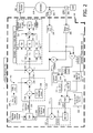
- Fig. 2 is a block diagram of a voltage regulator that may be used with the system shown in Fig. 1 .
- Fig. 3 is a flowchart of an exemplary method of tuning a reactive droop compensation of a generator in the system shown in Fig. 1 .
- the embodiments described herein relate to voltage regulators for controlling generators in parallel power generation systems. More specifically, the embodiments relate to a voltage regulator that is configured to simulate a reactive load applied to a parallel power generation system. More particularly, the embodiments described herein facilitate using a voltage regulator associated with a generator to simulate a reactive load for tuning a power factor, voltage droop, and/or other various properties of a parallel generator power generation system. Moreover, the embodiments described herein facilitate reducing costs associated with technician labor and costly reactive load rentals. While the embodiments illustrate a three phase electric generator, the embodiments described herein may be included within generators having any number of phases, including single phase and multiple phase electric generators.
- FIG. 1 is a schematic block diagram of a power generation system 100.
- power generation system 100 includes a voltage regulator 102 coupled to a first or main generator 104.
- Voltage regulator 102 is configured to monitor and control a generator excitation voltage to control the voltage output in main generator 104.
- power generation system 100 further includes at least one secondary generator 106 coupled in parallel to generator 104.
- Secondary generator 106 includes a separate voltage regulator (not shown) for controlling voltage output of secondary generator 106.
- Generators 104 and 106 are coupled in parallel when connecting the respective output voltages together at connection point 108. Connection point 108 couples generators 104 and 106 to a load 110.
- main generator 104 is an AC generator.
- main generator 104 includes any type of known generator, including but not limited to an AC induction generator, a permanent-magnet generator, an AC synchronous generator, or a switched-reluctance generator.
- main generator 104 is a three-phase AC synchronous generator. More specifically, main generator 104 includes a rotor (not shown) that rotates relative to a stator (not shown).
- the rotor may include a set of electrical field coils that may be energized by a field excitation current delivered to the field coils.
- the rotor is rotated by prime mover 106.
- the stator of main generator 104 includes a set of stationary coils positioned about the rotor such that the rotor may rotate within the stator. As the rotor rotates, an AC current is induced in the stationary coils. This current is directed out of main generator 104 in the form of an AC power signal.
- the output voltage of main generator 104 may be controlled by controlling a magnitude of the field current applied to the field coils.
- main generator 104 delivers more active power to compensate for the change in load 110 by holding the voltage substantially constant, causing an increase in the current.
- main generator 104 produces more reactive power in the form of reactive volt-amperes (VARs), which raises voltage of system 100.
- VARs reactive volt-amperes
- generators 104 and 106 are coupled in parallel to provide back-up voltage capability to provide power if one of generators 104 and 106 were to fail. More specifically, if the field excitation on main generator 104 becomes excessive and causes a circulating current to flow between generators 104 and 106, this current will appear as a lagging power factor (inductive load) to main generator 104 and a leading power factor (capacitive load) to secondary generator 106. Coupling generators 104 and 106 in parallel enables voltage regulator 102 to decrease the field excitation on main generator 104 having the lagging power factor and increase the field excitation on secondary generator 106 having the leading power factor so as to minimize the circulating currents between generators 104 and 106. The aforementioned process may be referred to as reactive droop compensation.
- voltage regulator 102 When coupled in parallel, each of generators 104 and 106 is tuned the reactive load sharing properties of system 100.
- voltage regulator 102 includes a simulated reactive load mode for simulating a reactive load on generator 104 such that a technician may tune system 100 to a desired power factor or may tune other properties before applying load 110. More specifically, voltage regulator 102 enables tuning a reactive droop compensation of generator 104 in parallel power generation system 100. Voltage regulator 102 enables a technician to use a purely resistive load for setting a simulated power factor of about from -1 to 1 for the desired load. Simulation of the power factor enables the technician to simulate inductive and/or capacitive loads.
- a typical resistive load bank (not shown) is applied to main generator 104 and, internally, voltage regulator 102 makes calculations as though the load were a reactive load bank with the power factor inputted by the technician. Moreover, the technician can simulate a final equilibrium point of main generator 104 and can then determine how much main generator 104 should be drooping in voltage. Simulating the final equilibrium may be done using one generator and a load bank, rather than having to actually first couple multiple generators in parallel. Without simulation, if the voltage set point for a generator is wrong, it could trip a breaker or damage equipment because of excessive load demand.
- voltage regulator 102 provides technicians a safe environment that enables them to evaluate the voltage droop behavior or main generator 104 using simulated reactance before the generators are actually connected to the system.
- the simulated mode enables technicians to test droop voltage without having to buy or rent a reactive load bank, which is often unavailable or costly to obtain.
- Fig. 2 is a block diagram of voltage regulator 102 (shown in Fig. 1 ) that may be used with system 100 (shown in Fig. 1 ).
- the magnitude of AC voltage at main generator 104 (shown in Fig. 1 ) is determined by the level of current in a generator exciter 200, which receives an excitation signal from voltage regulator 102 and applies it to main generator 104.
- the magnitude of main generator 104 AC output voltage may require that potential transformers 202 be used to step down the generator AC voltage to an appropriate level for voltage sensing inputs 204 of voltage regulator 102.
- Main generator 104 current levels are sensed using current transformers 206.
- the secondary windings of current transformers 206 are input into current sensing inputs 208 of voltage regulator 102.
- apparent, real and reactive power are each computed by voltage regulator 102.
- Voltage regulator 102 computes active real power 212 by vectorially multiplying the current of main generator 104 by the phase voltage of main generator 104.
- the resulting vector product 212 represents the active power delivered by main generator 104 to resistive load bank 110.
- Voltage regulator 102 calculates apparent power by a scalar multiplication 214 of the average sensed generator phase voltages 204 and average sensed line currents 208. Determining the ratio 220 of real active power 212 to apparent power 214 provides actual power factor 222 of main generator 104.
- actual power factor 222 is calculated using the Pythagorean Theorem by a division function 220, which divides active real power 212 by apparent power 214.
- a simulated power factor 224 is instead input into multiplexer 223.
- a user may set a software switch 225 for simulating reactive power.
- Software switch 225 controls a multiplexer 223 that channels either actual power factor 222 or simulated power factor 224, fabricated through a user-defined simulated power factor 221, to be used as an input into a reactive power calculator 227.
- Reactive power calculator 227 multiplies apparent power 214 by the sine of a power factor angle, which is calculated by an inverse tangent trigonometric function 226.
- a numerical value of one is used to represent rated reactive power of generator 104.
- the per-unit calculation is performed by a division function 232, which divides calculated reactive power 228 by rated reactive power 234 of generator 104.
- Per-unit reactive power 235 is input into a droop compensation calculator 237.
- a user-selected droop percentage 236 is defined, which represents the droop in the voltage of generator 104 when rated reactive power 234 is being delivered by generator 104.
- User-selected droop 236 is multiplied by per-unit reactive power 235, which results in the desired per-unit value of generator voltage droop 238.
- the per-unit value of voltage droop 238 is multiplied by the value of generator per-unit voltage setpoint 240 and the resulting droop compensation signal 239 is obtained.
- droop compensation output 239 is inputted as a negative value into main generator 104 AC voltage regulator summing junction 242.
- Summing junction 242 also includes main generator 104 AC voltage set point 244 as an input and the negative feedback value of actual generator AC voltage 204.
- the output 247 of summing junction 242 represents the error signal of the generator voltage control loop and is inputted into a generator voltage PID controller 246.
- Generator voltage PID controller 246 acts on output 247 of summing junction 242 by performing a time-based integration function 248 and a time-based derivative function 250.
- Each of signals 248 and 250, along with unmodified signal 252 is inputted into corresponding gain functions, Kp 254, Ki 256, and Kd 258.
- the outputs of gain functions Kp 254, Ki 256, and Kd 258 are summed in a summing junction 260.
- the output of summing junction 260 is inputted into a gain function 262.
- the output of gain function 262 is inputted into a power amplification stage 264 that drives the required amount of excitation current into generator exciter field winding 200.
- the level of current in exciter field winding 200 determines the level of excitation in the main field of main generator 104.
- a technician places voltage regulator 102 into the simulated reactive power mode using software switch 225.
- multiplexer 223 takes its input from simulated power factor 224 to compute a simulated value of calculated reactive power 228.
- PID controller 246 drives the output of the voltage regulator 102 to control the output voltage of generator 104 to match the desired value of PID input signal 247.
- the magnitude of simulated reactive power is controlled by the actual value of apparent power 214 flowing in resistive load bank 110 and user-defined value of simulated power factor 221. Moreover, voltage regulator 102 controls an excitation signal to the generator based at least in part on the simulated droop compensation voltage. Once the proper droop settings 236 are achieved, software switch 228 is placed back into its normal mode to enable actual power factor 222 to channel through multiplexer 233 to perform droop compensation 227, 232, and 237.
- Fig. 3 is a flowchart 300 of an exemplary method of tuning a reactive droop compensation of generator 104 (shown in Fig. 1 ) in parallel power generation system 100 (shown in Fig. 1 ).
- the method includes applying 302 a resistive load bank to generator 104.
- the method includes computing 304 a simulated droop compensation voltage for generator 104 using voltage regulator 102 (shown in Fig. 1 ) associated with generator 104.
- computing the simulated droop compensation voltage includes inputting a desired power factor into voltage regulator 102 and computing reactive power using the desired power factor.
- Computing the simulated droop compensation voltage further includes computing a ratio of the reactive power and rated machine parameters of generator 104, scaling the ratio by a droop percentage, and multiplying the scaled ratio by a voltage set point for generator 104.
- the method further includes controlling 306 an excitation signal to generator 104 based at least in part on the simulated droop compensation voltage using voltage regulator 102.
- controlling the excitation signal includes tuning voltage gains of a voltage controller included in voltage regulator 102 and applying the simulated droop compensation voltage to generator 104.
- controlling the excitation signal may include inducing generator 104 to share reactive power proportionately with at least one other generator coupled in parallel to generator 104 in system 100.
- controlling the excitation signal may include protecting generator 104 from exceeding a voltage set point.
- the exemplary embodiments described herein facilitate creating a simulative reactive load mode in a voltage regulator of a generator in a parallel power generation system. More particularly, the embodiments described herein facilitate using a voltage regulator associated with a generator to simulate a reactive load for tuning a power factor, voltage droop, and/or other various properties of a parallel generator power generation system. Moreover, the embodiments described herein facilitate reducing costs associated with technician labor and costly reactive load rentals.
- Exemplary embodiments of a voltage regulator and methods for simulating reactive power in parallel power generation systems are described above in detail.
- the size ranges disclosed herein include all the sub-ranges therebetween.
- the methods and systems are not limited to the specific embodiments described herein, but rather, components of systems and/or steps of the methods may be utilized independently and separately from other components and/or steps described herein.
- the methods may also be used in combination with other manufacturing systems and methods, and are not limited to practice with only the systems and methods as described herein. Rather, the exemplary embodiment can be implemented and utilized in connection with many other electrical component applications.
Landscapes
- Engineering & Computer Science (AREA)
- Power Engineering (AREA)
- Control Of Eletrric Generators (AREA)
Abstract
Description
- The embodiments described herein relate generally to parallel power generation systems, and more particularly, to methods and systems for tuning reactive droop compensation of generators in parallel power generation systems.
- The need for efficient power at affordable prices is ever increasing in many areas such as, for example, industrial, commercial, and consumer applications. As the need for power increases, so does the need for uninterrupted power. Many industrial applications require twenty four hour a day operation, therefore, loss of power can have severe economic consequences. One way power suppliers provide uninterrupted power is to employ parallel voltage generating systems. By paralleling generators, power can be delivered reliably because one generator can provide power for another when it fails. Such systems share reactive loads proportionally using reactive droop compensation.
- Set-up for such parallel generator systems requires adjustment of voltage droop in proportion to a reactive load. Typically, two or more generators are connected in parallel, and a reactive load is applied using an inductive load bank. Load sharing is accomplished by setting the droop characteristic of each generator accordingly. However, set-up normally occurs in the field where reactive load banks are prohibitively expensive and are not normally available to technicians who set up generators in such applications.
- In one aspect, a voltage regulator is provided for tuning a reactive droop compensation of a generator in a parallel power generation. The voltage regulator is configured to compute a simulated droop compensation voltage for the generator and control an excitation signal to the generator based at least in part on the simulated droop compensation voltage.
- In another aspect, a method is provided for tuning a reactive droop compensation of a generator in a parallel power generation system. The method includes applying a resistive load bank to the generator, computing a simulated droop compensation voltage for the generator using a voltage regulator associated with the generator, and controlling an excitation signal to the generator based at least in part on the simulated droop compensation voltage using the voltage regulator.
- In yet another aspect, a parallel power generation system is provided. The system includes a first generator configured to produce an electrical output to drive a load and a voltage regulator for tuning a reactive droop compensation of the first generator. The voltage regulator is configured to compute a simulated droop compensation voltage for the generator and control an excitation signal to the generator based at least in part on the simulated droop compensation voltage.
-
FIG. 1 is a schematic block diagram of a power generation system. -
Fig. 2 is a block diagram of a voltage regulator that may be used with the system shown inFig. 1 . -
Fig. 3 is a flowchart of an exemplary method of tuning a reactive droop compensation of a generator in the system shown inFig. 1 . - The embodiments described herein relate to voltage regulators for controlling generators in parallel power generation systems. More specifically, the embodiments relate to a voltage regulator that is configured to simulate a reactive load applied to a parallel power generation system. More particularly, the embodiments described herein facilitate using a voltage regulator associated with a generator to simulate a reactive load for tuning a power factor, voltage droop, and/or other various properties of a parallel generator power generation system. Moreover, the embodiments described herein facilitate reducing costs associated with technician labor and costly reactive load rentals. While the embodiments illustrate a three phase electric generator, the embodiments described herein may be included within generators having any number of phases, including single phase and multiple phase electric generators.
-
FIG. 1 is a schematic block diagram of apower generation system 100. In the exemplary embodiment,power generation system 100 includes avoltage regulator 102 coupled to a first ormain generator 104.Voltage regulator 102 is configured to monitor and control a generator excitation voltage to control the voltage output inmain generator 104. In the exemplary embodiment,power generation system 100 further includes at least onesecondary generator 106 coupled in parallel togenerator 104.Secondary generator 106 includes a separate voltage regulator (not shown) for controlling voltage output ofsecondary generator 106.Generators connection point 108.Connection point 108couples generators load 110. - In the exemplary embodiment,
generators Generators main generator 104. In the exemplary embodiment,main generator 104 is an AC generator. Moreover,main generator 104 includes any type of known generator, including but not limited to an AC induction generator, a permanent-magnet generator, an AC synchronous generator, or a switched-reluctance generator. In the exemplary embodiment,main generator 104 is a three-phase AC synchronous generator. More specifically,main generator 104 includes a rotor (not shown) that rotates relative to a stator (not shown). The rotor may include a set of electrical field coils that may be energized by a field excitation current delivered to the field coils. The rotor is rotated byprime mover 106. The stator ofmain generator 104 includes a set of stationary coils positioned about the rotor such that the rotor may rotate within the stator. As the rotor rotates, an AC current is induced in the stationary coils. This current is directed out ofmain generator 104 in the form of an AC power signal. The output voltage ofmain generator 104 may be controlled by controlling a magnitude of the field current applied to the field coils. - During operation, as
load 110 increases,main generator 104 delivers more active power to compensate for the change inload 110 by holding the voltage substantially constant, causing an increase in the current. By increasing current,main generator 104 produces more reactive power in the form of reactive volt-amperes (VARs), which raises voltage ofsystem 100. When current inmain generator 104 is decreased,system 100 voltage lowers, and VARs are absorbed bymain generator 104. - In the exemplary embodiment,
generators generators main generator 104 becomes excessive and causes a circulating current to flow betweengenerators main generator 104 and a leading power factor (capacitive load) tosecondary generator 106.Coupling generators voltage regulator 102 to decrease the field excitation onmain generator 104 having the lagging power factor and increase the field excitation onsecondary generator 106 having the leading power factor so as to minimize the circulating currents betweengenerators - When coupled in parallel, each of
generators system 100. In the exemplary embodiment,voltage regulator 102 includes a simulated reactive load mode for simulating a reactive load ongenerator 104 such that a technician may tunesystem 100 to a desired power factor or may tune other properties before applyingload 110. More specifically,voltage regulator 102 enables tuning a reactive droop compensation ofgenerator 104 in parallelpower generation system 100.Voltage regulator 102 enables a technician to use a purely resistive load for setting a simulated power factor of about from -1 to 1 for the desired load. Simulation of the power factor enables the technician to simulate inductive and/or capacitive loads. A typical resistive load bank (not shown) is applied tomain generator 104 and, internally,voltage regulator 102 makes calculations as though the load were a reactive load bank with the power factor inputted by the technician. Moreover, the technician can simulate a final equilibrium point ofmain generator 104 and can then determine how muchmain generator 104 should be drooping in voltage. Simulating the final equilibrium may be done using one generator and a load bank, rather than having to actually first couple multiple generators in parallel. Without simulation, if the voltage set point for a generator is wrong, it could trip a breaker or damage equipment because of excessive load demand. Accordingly,voltage regulator 102 provides technicians a safe environment that enables them to evaluate the voltage droop behavior ormain generator 104 using simulated reactance before the generators are actually connected to the system. In addition, the simulated mode enables technicians to test droop voltage without having to buy or rent a reactive load bank, which is often unavailable or costly to obtain. -
Fig. 2 is a block diagram of voltage regulator 102 (shown inFig. 1 ) that may be used with system 100 (shown inFig. 1 ). The magnitude of AC voltage at main generator 104 (shown inFig. 1 ) is determined by the level of current in agenerator exciter 200, which receives an excitation signal fromvoltage regulator 102 and applies it tomain generator 104. The magnitude ofmain generator 104 AC output voltage may require thatpotential transformers 202 be used to step down the generator AC voltage to an appropriate level forvoltage sensing inputs 204 ofvoltage regulator 102.Main generator 104 current levels are sensed usingcurrent transformers 206. The secondary windings ofcurrent transformers 206 are input intocurrent sensing inputs 208 ofvoltage regulator 102. - In the exemplary embodiment, apparent, real and reactive power are each computed by
voltage regulator 102.Voltage regulator 102 computes activereal power 212 by vectorially multiplying the current ofmain generator 104 by the phase voltage ofmain generator 104. The resultingvector product 212 represents the active power delivered bymain generator 104 toresistive load bank 110.Voltage regulator 102 calculates apparent power by ascalar multiplication 214 of the average sensedgenerator phase voltages 204 and average sensedline currents 208. Determining theratio 220 of realactive power 212 toapparent power 214 providesactual power factor 222 ofmain generator 104. In one embodiment,actual power factor 222 is calculated using the Pythagorean Theorem by adivision function 220, which divides activereal power 212 byapparent power 214. In an alternative embodiment, asimulated power factor 224 is instead input intomultiplexer 223. - In the exemplary embodiment, to make use of the simulated reactive power mode of
voltage regulator 102, in a reactive droop compensation mode, a user may set asoftware switch 225 for simulating reactive power.Software switch 225 controls amultiplexer 223 that channels eitheractual power factor 222 orsimulated power factor 224, fabricated through a user-definedsimulated power factor 221, to be used as an input into areactive power calculator 227.Reactive power calculator 227 multipliesapparent power 214 by the sine of a power factor angle, which is calculated by an inverse tangent trigonometric function 226. An output of calculatedreactive power 228, which is in units of VARs, is converted to a per-unit value 235 based on a user-input value of ratedreactive power 234 ofgenerator 104. In the per-unit measurement scheme, a numerical value of one is used to represent rated reactive power ofgenerator 104. The per-unit calculation is performed by a division function 232, which divides calculatedreactive power 228 by ratedreactive power 234 ofgenerator 104. Per-unitreactive power 235 is input into adroop compensation calculator 237. Withindroop compensation calculator 237, a user-selecteddroop percentage 236 is defined, which represents the droop in the voltage ofgenerator 104 when ratedreactive power 234 is being delivered bygenerator 104. User-selecteddroop 236 is multiplied by per-unitreactive power 235, which results in the desired per-unit value ofgenerator voltage droop 238. The per-unit value ofvoltage droop 238 is multiplied by the value of generator per-unit voltage setpoint 240 and the resultingdroop compensation signal 239 is obtained. - In the exemplary embodiment,
droop compensation output 239 is inputted as a negative value intomain generator 104 AC voltageregulator summing junction 242. Summingjunction 242 also includesmain generator 104 ACvoltage set point 244 as an input and the negative feedback value of actualgenerator AC voltage 204. Theoutput 247 of summingjunction 242 represents the error signal of the generator voltage control loop and is inputted into a generatorvoltage PID controller 246. Generatorvoltage PID controller 246 acts onoutput 247 of summingjunction 242 by performing a time-basedintegration function 248 and a time-basedderivative function 250. Each ofsignals Kp 254,Ki 256, andKd 258. These individually adjustable gains may be adjusted to meet the dynamic performance, system stability, and steady-state voltage regulation requirements ofsystem 100. The outputs ofgain functions Kp 254,Ki 256, andKd 258 are summed in a summingjunction 260. The output of summingjunction 260 is inputted into again function 262. The output ofgain function 262 is inputted into apower amplification stage 264 that drives the required amount of excitation current into generator exciter field winding 200. - The level of current in exciter field winding 200 determines the level of excitation in the main field of
main generator 104. By tuninggains Kp 254,Ki 256, andKd 258 of generatorvoltage PID controller 246 and applying the amount ofdroop percentage 236 needed for reactive load sharing, the desired response ofmain generator 104 to varying load demands is achieved. - In the exemplary embodiment, to simulate droop compensation, a technician places
voltage regulator 102 into the simulated reactive power mode usingsoftware switch 225. In the simulated reactive power mode,multiplexer 223 takes its input fromsimulated power factor 224 to compute a simulated value of calculatedreactive power 228. The simulated value of calculatedreactive power 228, after processing through per-unit function 232 and thedroop compensation calculator 237, results in adroop compensation signal 239 causing a voltage droop ininput signal 247 ofPID controller 246.PID controller 246 drives the output of thevoltage regulator 102 to control the output voltage ofgenerator 104 to match the desired value ofPID input signal 247. The magnitude of simulated reactive power is controlled by the actual value ofapparent power 214 flowing inresistive load bank 110 and user-defined value ofsimulated power factor 221. Moreover,voltage regulator 102 controls an excitation signal to the generator based at least in part on the simulated droop compensation voltage. Once theproper droop settings 236 are achieved,software switch 228 is placed back into its normal mode to enableactual power factor 222 to channel through multiplexer 233 to performdroop compensation -
Fig. 3 is aflowchart 300 of an exemplary method of tuning a reactive droop compensation of generator 104 (shown inFig. 1 ) in parallel power generation system 100 (shown inFig. 1 ). In the exemplary embodiment, the method includes applying 302 a resistive load bank togenerator 104. - Once the resistive load bank is applied, the method includes computing 304 a simulated droop compensation voltage for
generator 104 using voltage regulator 102 (shown inFig. 1 ) associated withgenerator 104. In the exemplary embodiment, computing the simulated droop compensation voltage includes inputting a desired power factor intovoltage regulator 102 and computing reactive power using the desired power factor. Computing the simulated droop compensation voltage further includes computing a ratio of the reactive power and rated machine parameters ofgenerator 104, scaling the ratio by a droop percentage, and multiplying the scaled ratio by a voltage set point forgenerator 104. - In the exemplary embodiment, the method further includes controlling 306 an excitation signal to
generator 104 based at least in part on the simulated droop compensation voltage usingvoltage regulator 102. In some embodiments, controlling the excitation signal includes tuning voltage gains of a voltage controller included involtage regulator 102 and applying the simulated droop compensation voltage togenerator 104. In other embodiments, controlling the excitation signal may include inducinggenerator 104 to share reactive power proportionately with at least one other generator coupled in parallel togenerator 104 insystem 100. In yet other embodiments, controlling the excitation signal may include protectinggenerator 104 from exceeding a voltage set point. - The exemplary embodiments described herein facilitate creating a simulative reactive load mode in a voltage regulator of a generator in a parallel power generation system. More particularly, the embodiments described herein facilitate using a voltage regulator associated with a generator to simulate a reactive load for tuning a power factor, voltage droop, and/or other various properties of a parallel generator power generation system. Moreover, the embodiments described herein facilitate reducing costs associated with technician labor and costly reactive load rentals.
- Exemplary embodiments of a voltage regulator and methods for simulating reactive power in parallel power generation systems are described above in detail. The size ranges disclosed herein include all the sub-ranges therebetween. The methods and systems are not limited to the specific embodiments described herein, but rather, components of systems and/or steps of the methods may be utilized independently and separately from other components and/or steps described herein. For example, the methods may also be used in combination with other manufacturing systems and methods, and are not limited to practice with only the systems and methods as described herein. Rather, the exemplary embodiment can be implemented and utilized in connection with many other electrical component applications.
- Although specific features of various embodiments of the invention may be shown in some drawings and not in others, this is for convenience only. In accordance with the principles of the invention, any feature of a drawing may be referenced and/or claimed in combination with any feature of any other drawing.
- This written description uses examples to disclose the invention, including the best mode, and also to enable any person skilled in the art to practice the invention, including making and using any devices or systems and performing any incorporated methods. The patentable scope of the invention is defined by the claims, and may include other examples that occur to those skilled in the art. Such other examples are intended to be within the scope of the claims if they have structural elements that do not differ from the literal language of the claims, or if they include equivalent structural elements with insubstantial differences from the literal languages of the claims.
Claims (15)
- A voltage regulator for tuning a reactive droop compensation of a generator in a parallel power generation system, said voltage regulator configured to:compute a simulated droop compensation voltage for the generator; andcontrol an excitation signal to the generator based at least in part on the simulated droop compensation voltage.
- The voltage regulator of Claim 1, wherein said voltage regulator comprises a switching device configured to switch said voltage regulator to a simulated reactive load mode.
- The voltage regulator of Claim 1, wherein to compute a simulated droop compensation voltage, said voltage regulator further configured to:receive a desired power factor input by a user;compute reactive power using the desired power factor;compute a ratio of the reactive power and rated machine parameters of the generator;scale the ratio by a droop percentage; andmultiply the scaled ratio by a voltage set point for the generator.
- The voltage regulator of Claim 1, wherein to control an excitation signal to the generator, said voltage regulator further configured to:tune voltage gains of a voltage controller included in said voltage regulator; andapply the simulated droop compensation voltage to the generator.
- The voltage regulator of Claim 1, wherein to control an excitation signal to the generator, said voltage regulator further configured to share reactive power proportionately with at least one other generator coupled in parallel to the generator.
- The voltage regulator of Claim 1, wherein to control an excitation signal to the generator, said voltage regulator further configured to protect the generator from exceeding a voltage set point.
- The voltage regulator of Claim 1, comprising an analog input for voltage set point control by a user.
- The voltage regulator of Claim 1, wherein during operation of the power generation system, said voltage regulator further configured to:measure an output voltage and an output current of the generator;compute actual reactive power output by the generator; andregulate the generator reactive power in accordance with the simulated droop compensation voltage.
- A method of tuning a reactive droop compensation of a generator in a parallel power generation system, said method comprising:applying a resistive load bank to the generator;computing a simulated droop compensation voltage for the generator using a voltage regulator associated with the generator; andcontrolling an excitation signal to the generator based at least in part on the simulated droop compensation voltage using the voltage regulator.
- The method of Claim 9, further comprising switching the voltage regulator to a simulated reactive load mode.
- The method of Claim 9, wherein computing a simulated droop compensation voltage comprises:inputting a desired power factor into the voltage regulator;computing reactive power using the desired power factor;computing a ratio of the reactive power and rated machine parameters of the generator;scaling the ratio by a droop percentage; andmultiplying the scaled ratio by a voltage set point for the generator.
- The method of Claim 9, wherein controlling an excitation signal to the generator further comprises:tuning voltage gains of a voltage controller included in the voltage regulator; andapplying the simulated droop compensation voltage to the generator.
- The method of Claim 9, wherein controlling an excitation signal to the generator further comprises inducing the generator to share reactive power proportionately with at least one other paralleled generator in the power generation system.
- The method of Claim 9, wherein controlling an excitation signal to the generator further comprises protecting the generator from exceeding a voltage set point.
- A parallel power generation system comprising:a first generator configured to produce an electrical output to drive a load; anda voltage regulator as claimed in any of claims 1 to 8, for tuning a reactive droop compensation of said first generator.
Applications Claiming Priority (1)
| Application Number | Priority Date | Filing Date | Title |
|---|---|---|---|
| US13/655,137 US9484850B2 (en) | 2012-10-18 | 2012-10-18 | Voltage regulator and methods for simulating reactive power in parallel power generation systems |
Publications (2)
| Publication Number | Publication Date |
|---|---|
| EP2722955A2 true EP2722955A2 (en) | 2014-04-23 |
| EP2722955A3 EP2722955A3 (en) | 2017-10-18 |
Family
ID=49328453
Family Applications (1)
| Application Number | Title | Priority Date | Filing Date |
|---|---|---|---|
| EP13188676.4A Withdrawn EP2722955A3 (en) | 2012-10-18 | 2013-10-15 | Voltage regulator and methods for simulating reactive power in parallel power generation systems |
Country Status (3)
| Country | Link |
|---|---|
| US (1) | US9484850B2 (en) |
| EP (1) | EP2722955A3 (en) |
| CN (1) | CN103792852B (en) |
Cited By (4)
| Publication number | Priority date | Publication date | Assignee | Title |
|---|---|---|---|---|
| CN104318836A (en) * | 2014-11-04 | 2015-01-28 | 江苏工程职业技术学院 | Computer-controlled power factor compensation demonstration and experiment device and experiment method |
| WO2018141695A1 (en) | 2017-02-03 | 2018-08-09 | Moteurs Leroy-Somer | Method for regulating alternators connected in parallel for the distribution of a reactive load |
| EP3928424A4 (en) * | 2019-02-22 | 2022-11-23 | Basler Electric Company | ADVANCED COUNTERCURRENT COMPENSATION SYSTEM AND METHOD FOR IMPROVING REACTIVE CURRENT SHARING |
| CN112018800B (en) * | 2020-07-17 | 2023-07-28 | 中国电力科学研究院有限公司 | A method and system for adjusting flexible DC control mode |
Families Citing this family (14)
| Publication number | Priority date | Publication date | Assignee | Title |
|---|---|---|---|---|
| US9893524B2 (en) * | 2012-12-20 | 2018-02-13 | Abb Schweiz Ag | Coordinated control method of generator and SVC for improving power throughput and controller thereof |
| EP2757257B1 (en) * | 2013-01-22 | 2017-11-22 | GE Renewable Technologies | Methods and arrangements for controlling power generators |
| EP2868919A1 (en) * | 2013-11-05 | 2015-05-06 | Openhydro IP Limited | Turbulence protection system and method for turbine generators |
| US9882386B2 (en) * | 2014-04-23 | 2018-01-30 | Nec Corporation | Consensus-based distributed cooperative control for microgrid voltage regulation and reactive power sharing |
| CN104200022B (en) * | 2014-08-28 | 2017-08-04 | 北京航空航天大学 | A Distributed Interaction Method for Continuous System Model |
| CN105743085B (en) | 2014-12-12 | 2019-11-26 | 通用电气公司 | To the system and method for at least one load supplying |
| CN104698865B (en) * | 2015-03-04 | 2017-11-10 | 广州供电局有限公司 | Elevator is influenceed simulation system and its analogy method by voltage dip |
| KR101809787B1 (en) * | 2015-03-10 | 2017-12-15 | 엘에스산전 주식회사 | Electricity providing system including battery energy storage system |
| JP2016167954A (en) * | 2015-03-10 | 2016-09-15 | シンフォニアテクノロジー株式会社 | Power generating installation and power-factor control device thereof |
| CN110456657B (en) * | 2019-07-18 | 2022-10-04 | 中山瑞信智能控制系统有限公司 | Simulation method of reluctance motor, embedded system and operation method |
| EP3994342B1 (en) * | 2019-08-06 | 2025-11-19 | Siemens Energy, Inc. | Combined cycle frequency control system and method |
| US12212145B2 (en) | 2020-05-29 | 2025-01-28 | Cummins Power Generation Inc. | Systems and methods for paralleling multiple power sources |
| CN116324312A (en) * | 2020-09-30 | 2023-06-23 | 大金工业株式会社 | Power control systems, machines and information processing systems |
| CN116754883B (en) * | 2023-08-22 | 2023-11-24 | 山东华天电气有限公司 | Multifunctional detection equipment and detection method for reactive power compensation device |
Family Cites Families (16)
| Publication number | Priority date | Publication date | Assignee | Title |
|---|---|---|---|---|
| US4410848A (en) * | 1981-06-08 | 1983-10-18 | Basler Electric Company | System for maintaining excitation of an alternator during excessive output current conditions |
| US5294879A (en) * | 1991-11-01 | 1994-03-15 | Basler Electric Company | Microprocessor-controlled regulator |
| US6285168B1 (en) | 1999-09-30 | 2001-09-04 | Rockwell Automation Technologies, Inc. | Reactive droop compensation system and method |
| US6218813B1 (en) | 1999-09-30 | 2001-04-17 | Rockwell Technologies, Llc | Cross current compensation system and method |
| US6522030B1 (en) * | 2000-04-24 | 2003-02-18 | Capstone Turbine Corporation | Multiple power generator connection method and system |
| US6583610B2 (en) * | 2001-03-12 | 2003-06-24 | Semtech Corporation | Virtual ripple generation in switch-mode power supplies |
| US6661214B1 (en) * | 2001-09-28 | 2003-12-09 | Itt Manufacturing Enterprises, Inc. | Droop compensation circuitry |
| US6924565B2 (en) * | 2003-08-18 | 2005-08-02 | General Electric Company | Continuous reactive power support for wind turbine generators |
| US7454637B2 (en) * | 2005-09-02 | 2008-11-18 | Intel Corporation | Voltage regulator having reduced droop |
| US7933101B2 (en) | 2007-02-15 | 2011-04-26 | Aka Information Design | Generator power plant protection system and method |
| US7923862B2 (en) * | 2009-10-06 | 2011-04-12 | General Electric Company | Reactive power regulation and voltage support for renewable energy plants |
| TWI456882B (en) * | 2010-06-25 | 2014-10-11 | Richtek Technology Corp | Voltage regulator and control circuit and method therefor |
| US20120029720A1 (en) * | 2010-07-29 | 2012-02-02 | Spirae, Inc. | Dynamic distributed power grid control system |
| ES2617753T3 (en) * | 2010-07-29 | 2017-06-19 | Spirae Llc | Dynamic control system of distributed electricity networks |
| CN103518169A (en) * | 2011-03-09 | 2014-01-15 | 佩特拉太阳能公司 | Distributed control of dynamic reactive power |
| TWI415359B (en) * | 2011-09-16 | 2013-11-11 | Nat Univ Tsing Hua | Drop control system for synchronous adjustment of commercial power parallel |
-
2012
- 2012-10-18 US US13/655,137 patent/US9484850B2/en active Active
-
2013
- 2013-10-15 EP EP13188676.4A patent/EP2722955A3/en not_active Withdrawn
- 2013-10-18 CN CN201310753598.7A patent/CN103792852B/en active Active
Non-Patent Citations (1)
| Title |
|---|
| None |
Cited By (5)
| Publication number | Priority date | Publication date | Assignee | Title |
|---|---|---|---|---|
| CN104318836A (en) * | 2014-11-04 | 2015-01-28 | 江苏工程职业技术学院 | Computer-controlled power factor compensation demonstration and experiment device and experiment method |
| WO2018141695A1 (en) | 2017-02-03 | 2018-08-09 | Moteurs Leroy-Somer | Method for regulating alternators connected in parallel for the distribution of a reactive load |
| US11233399B2 (en) | 2017-02-03 | 2022-01-25 | Moteurs Leroy-Somer | Method for regulating paralleled alternators in order to distribute reactive load |
| EP3928424A4 (en) * | 2019-02-22 | 2022-11-23 | Basler Electric Company | ADVANCED COUNTERCURRENT COMPENSATION SYSTEM AND METHOD FOR IMPROVING REACTIVE CURRENT SHARING |
| CN112018800B (en) * | 2020-07-17 | 2023-07-28 | 中国电力科学研究院有限公司 | A method and system for adjusting flexible DC control mode |
Also Published As
| Publication number | Publication date |
|---|---|
| CN103792852B (en) | 2018-07-20 |
| EP2722955A3 (en) | 2017-10-18 |
| CN103792852A (en) | 2014-05-14 |
| US20140111167A1 (en) | 2014-04-24 |
| US9484850B2 (en) | 2016-11-01 |
Similar Documents
| Publication | Publication Date | Title |
|---|---|---|
| US9484850B2 (en) | Voltage regulator and methods for simulating reactive power in parallel power generation systems | |
| De Carne et al. | Real-time primary frequency regulation using load power control by smart transformers | |
| US8510090B2 (en) | Conditioning device for energy supply networks | |
| El-Naggar et al. | Analysis of fault current contribution of Doubly-Fed Induction Generator Wind Turbines during unbalanced grid faults | |
| WO2010028689A9 (en) | Direct power control with component separation | |
| EP2683076A1 (en) | Virtual admittance controller based on static power converters | |
| Sharma et al. | Asynchronous generator with battery storage for standalone wind energy conversion system | |
| US20160357207A1 (en) | Dynamic calculation and control of synchronous machines | |
| Singh et al. | Development of dynamic test cases in OPAL-RT real-time power system simulator | |
| JP5986857B2 (en) | Voltage regulator | |
| Westman et al. | Modeling of a reciprocating engine-generator set for controller-hardware-in-the-loop testing of island microgrid control systems | |
| Guevara et al. | Modeling and Load Flow Analysis of a Microgrid Laboratory. | |
| Gyawali | Universal electronic load controller for microhydro power plant | |
| Diez-Maroto et al. | Modeling, sizing, and control of an excitation booster for enhancement of synchronous generators fault ride-through capability: Experimental validation | |
| KR20190028209A (en) | Apparatus and method for controlling cvcf ess capacity of stand-alone micro grid | |
| Yazdani et al. | Power Synchronization PID control method for grid-connected voltage-source converters | |
| Dehghanzade Golmaee et al. | Variable frequency transformer equipped with dynamic breaking resistors for controlling low frequency oscillation using hierarchical strategy | |
| Nemmour et al. | Advanced Backstepping controller for induction generator using multi-scalar machine model for wind power purposes | |
| Wang et al. | GENTPJ model dynamic performance | |
| Benhacine et al. | Low-cost three-phase self-excited induction generator for supplying isolated single-phase loads | |
| CN113615029B (en) | Method and three-phase inverter for feeding into a three-phase AC voltage network | |
| JP5938312B2 (en) | Voltage regulator | |
| Langwasser et al. | Smart transformer-based frequency support in variable inertia conditions | |
| Jankee | Synchronous generator and excitation system response to GIC | |
| Bukhari et al. | An inrush current elimination technique for line-interactive UPS systems during switching-in of an auxiliary load while feeding a main load |
Legal Events
| Date | Code | Title | Description |
|---|---|---|---|
| PUAI | Public reference made under article 153(3) epc to a published international application that has entered the european phase |
Free format text: ORIGINAL CODE: 0009012 |
|
| AK | Designated contracting states |
Kind code of ref document: A2 Designated state(s): AL AT BE BG CH CY CZ DE DK EE ES FI FR GB GR HR HU IE IS IT LI LT LU LV MC MK MT NL NO PL PT RO RS SE SI SK SM TR |
|
| AX | Request for extension of the european patent |
Extension state: BA ME |
|
| PUAL | Search report despatched |
Free format text: ORIGINAL CODE: 0009013 |
|
| AK | Designated contracting states |
Kind code of ref document: A3 Designated state(s): AL AT BE BG CH CY CZ DE DK EE ES FI FR GB GR HR HU IE IS IT LI LT LU LV MC MK MT NL NO PL PT RO RS SE SI SK SM TR |
|
| AX | Request for extension of the european patent |
Extension state: BA ME |
|
| RIC1 | Information provided on ipc code assigned before grant |
Ipc: H02J 3/16 20060101AFI20170914BHEP Ipc: H02P 9/14 20060101ALI20170914BHEP Ipc: H02J 3/18 20060101ALI20170914BHEP |
|
| STAA | Information on the status of an ep patent application or granted ep patent |
Free format text: STATUS: REQUEST FOR EXAMINATION WAS MADE |
|
| 17P | Request for examination filed |
Effective date: 20180418 |
|
| RBV | Designated contracting states (corrected) |
Designated state(s): AL AT BE BG CH CY CZ DE DK EE ES FI FR GB GR HR HU IE IS IT LI LT LU LV MC MK MT NL NO PL PT RO RS SE SI SK SM TR |
|
| STAA | Information on the status of an ep patent application or granted ep patent |
Free format text: STATUS: EXAMINATION IS IN PROGRESS |
|
| 17Q | First examination report despatched |
Effective date: 20200507 |
|
| GRAP | Despatch of communication of intention to grant a patent |
Free format text: ORIGINAL CODE: EPIDOSNIGR1 |
|
| STAA | Information on the status of an ep patent application or granted ep patent |
Free format text: STATUS: GRANT OF PATENT IS INTENDED |
|
| INTG | Intention to grant announced |
Effective date: 20220222 |
|
| STAA | Information on the status of an ep patent application or granted ep patent |
Free format text: STATUS: THE APPLICATION IS DEEMED TO BE WITHDRAWN |
|
| 18D | Application deemed to be withdrawn |
Effective date: 20220705 |