EP2722652B1 - Ultraschall-durchflussmesser und ultraschall- durchflussmessverfahren - Google Patents
Ultraschall-durchflussmesser und ultraschall- durchflussmessverfahren Download PDFInfo
- Publication number
- EP2722652B1 EP2722652B1 EP12772186.8A EP12772186A EP2722652B1 EP 2722652 B1 EP2722652 B1 EP 2722652B1 EP 12772186 A EP12772186 A EP 12772186A EP 2722652 B1 EP2722652 B1 EP 2722652B1
- Authority
- EP
- European Patent Office
- Prior art keywords
- ultrasonic
- pipe body
- pipe
- signal
- reflecting units
- Prior art date
- Legal status (The legal status is an assumption and is not a legal conclusion. Google has not performed a legal analysis and makes no representation as to the accuracy of the status listed.)
- Active
Links
Images


Classifications
-
- G—PHYSICS
- G01—MEASURING; TESTING
- G01F—MEASURING VOLUME, VOLUME FLOW, MASS FLOW OR LIQUID LEVEL; METERING BY VOLUME
- G01F1/00—Measuring the volume flow or mass flow of fluid or fluent solid material wherein the fluid passes through a meter in a continuous flow
- G01F1/66—Measuring the volume flow or mass flow of fluid or fluent solid material wherein the fluid passes through a meter in a continuous flow by measuring frequency, phase shift or propagation time of electromagnetic or other waves, e.g. using ultrasonic flowmeters
- G01F1/662—Constructional details
-
- G—PHYSICS
- G01—MEASURING; TESTING
- G01F—MEASURING VOLUME, VOLUME FLOW, MASS FLOW OR LIQUID LEVEL; METERING BY VOLUME
- G01F1/00—Measuring the volume flow or mass flow of fluid or fluent solid material wherein the fluid passes through a meter in a continuous flow
- G01F1/66—Measuring the volume flow or mass flow of fluid or fluent solid material wherein the fluid passes through a meter in a continuous flow by measuring frequency, phase shift or propagation time of electromagnetic or other waves, e.g. using ultrasonic flowmeters
- G01F1/667—Arrangements of transducers for ultrasonic flowmeters; Circuits for operating ultrasonic flowmeters
Definitions
- the present invention relates to an ultrasonic flow sensor and a method for ultrasonic flow measurement.
- an ultrasonic flow sensor has two mounting holes in a pipe body, and each mounting hole is equipped with an ultrasonic detecting element.
- Signal reflecting units are provided in the pipe body.
- Ultrasonic signal emitted from a first ultrasonic detecting element is transmitted to a second ultrasonic detecting element through the signal reflecting units. Based on the distance between the two ultrasonic detecting elements and the time that it takes for the ultrasonic signal to be transmitted between the two ultrasonic detecting elements, the liquid flow cross the pipe body per unit time is measured.
- ultrasonic flow sensors are normally equipped with signal reflecting units in the pipe body, a first ultrasonic transducer converts the electrical signal to an ultrasonic vibration signal, and after entering through a first mounting hole and reflected by a first signal reflecting unit, such vibration signal is transmitted to a second signal reflecting unit along the axial direction, whereby the vibration signal is reflected and transmitted through a second mounting hole, and a second ultrasonic transducer converts the ultrasonic vibration signal to an electrical signal.
- the existing structure has the following defects:
- ultrasonic flow sensor which is characterized by multiple reflections of ultrasonic signal and detection of straight-line distance of multiple segments in the pipe body, in order to improve the accuracy of measurement;
- the existing ultrasonic flow sensors need to increase the number of straight-line segments through which an ultrasonic signal crosses to improve the accuracy of measurement, and on the other hand, need to decrease the reflection times of the ultrasonic signal, and reduce the attenuation and the loss of the ultrasonic signal in the transmission process.
- the existing ultrasonic flow sensors as e.g. disclosed by WO02/44662-A1 and CN201740552-U , can not solve those technical problems.
- the object of the present invention to overcome the defects of the existing technology to provide an ultrasonic flow sensor and a method for ultrasonic flow measurement.
- the present invention can be more accurate to detect the liquid flow and reduce the attenuation of the signals, and at the same time, this invention can reduce pressure loss of the flow sensor, so that the reliability is also improved.
- the mounting hole may be provided with a mounting seat which comprises a mounting end and a fixing end, and the axis of the mounting end is parallel to the cross-section of the pipe body, and the axis of the fixing end is inclined with respect to the cross-section of the pipe body, and the ultrasonic detecting element is located at the fixing end of the mounting seat.
- the ultrasonic flow sensor may further include a clasping ring comprising a pressure ring and at least two clasping ears; and the mounting end of the mounting seat is provided with at least two fixing grooves, and each fixing groove comprises circumferentially rotary groove with which an inserting groove is communicated, and the clasping ears are corresponding to the fixing grooves; and on the exposed side of the clasping rings there is provided with at least two disassembling and assembling concaves.
- a clasping ring comprising a pressure ring and at least two clasping ears
- the mounting end of the mounting seat is provided with at least two fixing grooves, and each fixing groove comprises circumferentially rotary groove with which an inserting groove is communicated, and the clasping ears are corresponding to the fixing grooves; and on the exposed side of the clasping rings there is provided with at least two disassembling and assembling concaves.
- the ultrasonic detecting element may be provided with a flange, and a sealing ring is arranged between the clasping ring and the flange.
- the signal reflecting units may be only two in number.
- the ultrasonic detecting element may be located above the axis of the pipe body, and the center of the two signal reflecting units is lower than the axis of the pipe body, which is located respectively on the two opposite sides of the axis of the pipe body.
- the angle between the vertical line of the ultrasonic detecting element and the cross-section is of 15 degrees to 85 degrees.
- a method for ultrasonic flow measurement comprises:
- the ultrasonic detecting element may be a common ultrasonic transducer, the role of which is to convert electrical signals to ultrasonic vibration signals, or vice versa.
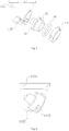
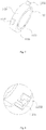
- an ultrasonic flow sensor includes a pipe body 10 with two mounting holes 111. Each mounting hole 111 is equipped with an ultrasonic detecting element 20. Signal reflecting units 30 are provided in the pipe body 10. The cross-section is perpendicular to an axis of the pipe body 10, and the axis of the two ultrasonic detecting elements 20 is inclined with respect to the cross-section of the pipe body 10.
- the pipe body 10 includes: an outer pipe 12 and an inner pipe 11 located in the outer pipe 12, and each of the signal reflecting units 30 is located on the inner wall of the inner pipe 11.
- the outer pipe 12 is provided with a positioning hole 114 which is provided with an adjusting screw 115, and the end of the adjusting screw 115 is pressed on the inner pipe 11.
- the outer wall of the inner pipe 11 is provided with an adjusting annular groove 11a, which is corresponding to the adjusting screw.
- the mounting hole 111 is provided with a mounting seat 112 which includes a mounting end 1121 and a fixing end 1122, and the axis of the mounting end 1121 is parallel to the cross-section of the pipe body 10, and the axis of the fixing end 1122 is inclined with respect to the cross-section of the pipe body 10, and the ultrasonic detecting element 20 is located at the fixing end 1122 of the mounting seat 112.
- the ultrasonic flow sensor further includes a clasping ring 113 comprising a pressure ring 1131 and at least two clasping ears 1132.
- the fixing end 1122 of the mounting seat 112 is provided with at least two fixing grooves 1123, and each fixing groove 1123 includes a circumferentially rotary groove 11231 with which an inserting groove 11232 is communicated, and the two clasping ears 1132 are corresponding to the fixing groove 1123; and on exposed side of the clasping rings 113 there is provided with at least two disassembling and assembling concaves 1133.
- the ultrasonic detecting element 20 is provided with a flange 21, and the sealing ring 22 is provided between the clasping ring 113 and the flange 21.
- the signal reflecting units 30 may be only two in number.
- the ultrasonic detecting element 20 is located above the axis of the pipe body 10, and the center of the two signal reflecting units 30 is lower than the axis of the pipe body 10, which is located respectively on the two opposite sides of the axis of the pipe body 10.
- the angle between vertical line of the ultrasonic detecting element 20 and the cross-section is of 15 degrees to 85 degrees.
- the method for ultrasonic flow measurement is as follows: a first ultrasonic detecting element 20 emits an ultrasonic signal, which is inclined with respect to the cross-section of the pipe body 10 and is transmitted to the signal reflecting units 30, whereby the ultrasonic signals is reflected to a second ultrasonic detecting element 20. Based on the distance between the two ultrasonic detecting elements 20 and the time that it takes for the ultrasonic signal to be transmitted between the two ultrasonic detecting elements 20, the liquid flow cross the pipe body per unit time is measured.
Landscapes
- Physics & Mathematics (AREA)
- Electromagnetism (AREA)
- Fluid Mechanics (AREA)
- General Physics & Mathematics (AREA)
- Measuring Volume Flow (AREA)
Claims (7)
- Ultraschallströmungssensor, umfassend:einen Rohrkörper (10) mit zwei Montagelöchern (111),zwei Ultraschallerfassungselemente (20), die jeweils an den zwei Montagelöchern (111) montiert sind, undSignalreflektionseinheiten (30), die im Inneren des Rohrkörpers (10) bereitgestellt sind, wobei eine Achse jedes der zwei Ultraschallerfassungselemente (20) in Bezug auf einen Querschnitt des Rohrkörpers (10) senkrecht zu einer Achse des Rohrkörpers geneigt ist, der Ultraschallströmungssensor dadurch gekennzeichnet ist, dass:der Rohrkörper (10) ferner Folgendes umfasst: ein äußeres Rohr (12) und ein inneres Rohr (11), das von dem äußeren Rohr (12) umhüllt ist, wobei sich jede der Signalreflektionseinheiten (30) auf einer inneren Wand des inneren Rohrs (11) befindet,das äußere Rohr (12) mit einem Positionierungsloch (114) bereitgestellt ist und eine Einstellschraube (115) in dem Positionierungsloch (114) bereitgestellt ist, wobei ein Ende der Einstellschraube (115) auf dem inneren Rohr (11) aufgepresst ist, undwobei eine äußere Wand des inneren Rohrs (11) mit einer ringförmigen Einstellnut (11a) bereitgestellt ist, die der Einstellschraube (115) entspricht.
- Ultraschallströmungssensor nach Anspruch 1, wobei das Montageloch (111) mit einem Montagesitz (112) bereitgestellt ist, der ein Montageende (1121) und ein Befestigungsende (1122) umfasst, und eine Achse des Montageendes (1121) parallel zu dem Querschnitt des Rohrkörpers (10) ist und eine Achse des Befestigungsendes (1122) in Bezug auf den Querschnitt des Rohrkörpers (10) geneigt ist und sich das Ultraschallerfassungselement (20) an dem Befestigungsende (1122) des Montagesitzes (112) befindet.
- Ultraschallströmungssensor nach Anspruch 2, wobei der Ultraschallströmungssensor ferner einen Klemmring (113) mit einem Druckring (1131) und mindestens zwei Klemmohren (1132) umfasst, das Befestigungsende (1122) des Montagesitzes (112) mit mindestens zwei Befestigungsnuten (1123) bereitgestellt ist und jede Befestigungsnut umlaufend eine Drehnut (11231) umfasst, mit der die Einsatznut (11232) kommuniziert, und die zwei Klemmohren (1132) den Befestigungsnuten (1123) entsprechen und mindestens zwei demontierende und montierende Konkavitäten (1133) auf einer freigelegten Seite der Klemmringe (113) bereitgestellt sind.
- Ultraschallströmungssensor nach Anspruch 1, wobei die Signalreflektionseinheiten (30) nur zwei an der Zahl sind.
- Ultraschallströmungssensor nach Anspruch 2, wobei sich das Ultraschallerfassungselement (20) über der Achse des Rohrkörpers (10) befindet, die Mitte der zwei Signalreflektionseinheiten (30) niedriger ist als die Achse des Rohrkörpers (10) und sich die zwei Signalreflektionseinheiten (30) jeweils auf zwei gegenüberliegenden Seiten der Achse des Rohrkörpers (10) befinden.
- Ultraschallströmungssensor nach Anspruch 2, wobei der Winkel zwischen einer vertikalen Linie des Ultraschallerfassungselements (20) und dem Querschnitt 15 Grad bis 85 Grad beträgt.
- Verfahren zum Ultraschallströmungsmessen, umfassend:Bereitstellen eines Rohrkörpers (10), umfassend: ein äußeres Rohr (12), ein inneres Rohr (11), das von dem äußeren Rohr (12) umhüllt ist, und eine oder mehrere Signalreflektionseinheiten (30), die sich auf einer inneren Wand des inneren Rohrs (11) befinden, wobei das äußere Rohr (12) mit einem Positionierungsloch (114) bereitgestellt ist und eine Einstellschraube (115) in dem Positionierungsloch (114) bereitgestellt ist, wobei ein Ende der Einstellschraube (115) auf dem inneren Rohr (11) aufgepresst ist und wobei eine äußere Wand des inneren Rohrs (11) mit einer ringförmigen Einstellnut (11a) bereitgestellt ist, die der Einstellschraube (115) entspricht.Abgeben eines Ultraschallsignals durch ein erstes Ultraschallerfassungselement (20), wobei das Ultraschallsignal in Bezug auf einen Querschnitt des Rohrkörpers (10) geneigt ist,Übertragen des Ultraschallsignals zu den Signalreflektionseinheiten (30), wodurch das Ultraschallsignal zu einem zweiten Ultraschallerfassungselement (20) reflektiert wird, undMessen von Flüssigkeitsströmung über den Rohrkörper (10) pro Zeiteinheit basierend auf dem Abstand zwischen zwei Ultraschallerfassungselementen (20) und Zeit, die das Ultraschallsignal benötigt, um zwischen den zwei Ultraschallerfassungselementen übertragen zu werden.
Applications Claiming Priority (2)
| Application Number | Priority Date | Filing Date | Title |
|---|---|---|---|
| CN201210194469.4A CN102706399B (zh) | 2012-06-13 | 2012-06-13 | 超声波流量计及超声波流量计量方法 |
| PCT/CN2012/078915 WO2013185406A1 (zh) | 2012-06-13 | 2012-07-20 | 超声波流量计及超声波流量计量方法 |
Publications (4)
| Publication Number | Publication Date |
|---|---|
| EP2722652A1 EP2722652A1 (de) | 2014-04-23 |
| EP2722652A4 EP2722652A4 (de) | 2015-04-08 |
| EP2722652B1 true EP2722652B1 (de) | 2018-06-06 |
| EP2722652B8 EP2722652B8 (de) | 2018-12-19 |
Family
ID=46899350
Family Applications (1)
| Application Number | Title | Priority Date | Filing Date |
|---|---|---|---|
| EP12772186.8A Active EP2722652B8 (de) | 2012-06-13 | 2012-07-20 | Ultraschall-durchflussmesser und ultraschall- durchflussmessverfahren |
Country Status (5)
| Country | Link |
|---|---|
| EP (1) | EP2722652B8 (de) |
| CN (1) | CN102706399B (de) |
| DE (1) | DE202012104552U1 (de) |
| ES (1) | ES2686022T3 (de) |
| WO (1) | WO2013185406A1 (de) |
Families Citing this family (13)
| Publication number | Priority date | Publication date | Assignee | Title |
|---|---|---|---|---|
| CN103323064A (zh) * | 2013-05-31 | 2013-09-25 | 合肥瑞纳表计有限公司 | 超声波多点反射流量计 |
| DE102013114744A1 (de) | 2013-12-20 | 2015-06-25 | Endress + Hauser Flowtec Ag | Messanordnung und Ultraschall-Durchflussmessgerät |
| DE102014010375B4 (de) * | 2014-07-12 | 2021-06-17 | Diehl Metering Gmbh | Ultraschallwandleranordnung sowie Ultraschallwasserzähler |
| EP4089374B1 (de) * | 2014-07-21 | 2025-09-03 | Apator Miitors ApS | Strömungsleitungseinsatz für ein ultraschall-durchflussmessgerät |
| CN106441471A (zh) * | 2016-10-14 | 2017-02-22 | 青岛海威茨仪表有限公司 | 一种大口径超声波流量计 |
| CN107219024B (zh) * | 2017-05-23 | 2023-08-08 | 安徽汉威电子有限公司 | 超声波热量表 |
| CN107300431B (zh) * | 2017-05-23 | 2023-08-29 | 安徽汉威电子有限公司 | 滑动微调式超声波热量表 |
| CN106989786B (zh) * | 2017-05-23 | 2023-09-01 | 安徽汉威电子有限公司 | 可观测的滑动微调式超声波热量表 |
| CN106949993B (zh) * | 2017-05-23 | 2023-10-27 | 安徽汉威电子有限公司 | 可观测的限定调节式超声波热量表 |
| EP3757527B1 (de) * | 2019-06-25 | 2021-06-09 | SICK Engineering GmbH | Ultraschall-durchflussmessgerät |
| CN111829602A (zh) * | 2020-08-13 | 2020-10-27 | 广州柏诚智能科技有限公司 | 超声波水表 |
| CN112525276A (zh) * | 2020-12-14 | 2021-03-19 | 北京化工大学 | 一种基于激光光路的外夹超声流量计安装误差模拟装置 |
| CN116447124A (zh) * | 2023-03-31 | 2023-07-18 | 利欧集团浙江泵业有限公司 | 一种带超声波流量检测控制的水泵及方法 |
Citations (1)
| Publication number | Priority date | Publication date | Assignee | Title |
|---|---|---|---|---|
| DE10327076B3 (de) * | 2003-06-13 | 2005-04-07 | Hydrometer Gmbh | Ultraschallzähler zur Bestimmung der Durchflussmenge eines strömenden Mediums |
Family Cites Families (21)
| Publication number | Priority date | Publication date | Assignee | Title |
|---|---|---|---|---|
| DE2461403C3 (de) * | 1974-12-24 | 1979-01-25 | Joseph Jericho Long Island N.Y. Baumoel (V.St.A.) | StrömungsmeBgerät |
| DE3544456A1 (de) * | 1985-12-16 | 1987-06-19 | Siemens Ag | Durchflussmessgeraet in ultraschalltechnik |
| NL8602690A (nl) * | 1986-10-27 | 1988-05-16 | Servex Bv | Inrichting voor het bepalen van de stromingssnelheid van een medium in een cylindrische leiding. |
| EP0559938B1 (de) * | 1992-03-11 | 1993-10-27 | Siemens Aktiengesellschaft | Durchflussmesseinrichtung für flüssige Medien nach dem Ultraschall-Laufzeitprinzip |
| DE50111872D1 (de) * | 2000-11-30 | 2007-02-22 | Landis & Gyr Gmbh | Durchflussmesser |
| US7194919B2 (en) * | 2003-05-29 | 2007-03-27 | Transonic Systems, Inc. | Acoustically coupled ultrasonic transit time flow sensors |
| DE102004061404A1 (de) * | 2004-12-21 | 2006-07-06 | Robert Bosch Gmbh | Ultraschall-Durchflussmesser und Verfahren zur Durchflussmessung mittels Ultraschall |
| CN201210067Y (zh) * | 2008-05-08 | 2009-03-18 | 申思 | 小管径管道燃气流量超声测量结构 |
| CN100578162C (zh) * | 2008-05-22 | 2010-01-06 | 谭文胜 | 一种超声波流量测量装置 |
| CN201622086U (zh) * | 2009-11-12 | 2010-11-03 | 中环天仪股份有限公司 | 超声波流量仪表的传感器装置 |
| CN201589631U (zh) * | 2009-12-16 | 2010-09-22 | 天津市光大伟业计量仪表技术有限公司 | 利用流量管内壁进行声波反射的超声波流量管 |
| CN201555623U (zh) * | 2009-12-17 | 2010-08-18 | 重庆市伟岸测器制造有限公司 | 一种超声节流装置 |
| CN101858762B (zh) * | 2010-05-19 | 2013-01-16 | 邓鲁坚 | 管壁反射式超声波流量传感器 |
| CN201740552U (zh) * | 2010-06-10 | 2011-02-09 | 重庆市伟岸测器制造股份有限公司 | 一种管壁反射式超声流量传感器 |
| DE102010040396A1 (de) * | 2010-09-08 | 2012-03-08 | Robert Bosch Gmbh | Durchflussmesser zur Erfassung einer Eigenschaft eines fluiden Mediums |
| CN201811811U (zh) * | 2010-11-02 | 2011-04-27 | 石家庄长通电器有限公司 | 一种超声波热量表换能器测量管段 |
| CN102062623B (zh) * | 2010-11-09 | 2012-06-20 | 郭荣岭 | 消除零点误差的超声波流量计 |
| CN202092691U (zh) * | 2011-05-06 | 2011-12-28 | 陈贤在 | 一种反射式超声波热量表的流量传感器 |
| CN102288236A (zh) * | 2011-05-06 | 2011-12-21 | 陈贤在 | 一种反射式超声波热量表的流量传感器 |
| CN202209967U (zh) * | 2011-08-02 | 2012-05-02 | 蒋韵坚 | 一种可拆卸反射块的v形反射超声波热量表的流量传感器 |
| CN202693050U (zh) * | 2012-06-13 | 2013-01-23 | 广州柏诚智能科技有限公司 | 超声波流量计 |
-
2012
- 2012-06-13 CN CN201210194469.4A patent/CN102706399B/zh active Active
- 2012-07-20 ES ES12772186.8T patent/ES2686022T3/es active Active
- 2012-07-20 WO PCT/CN2012/078915 patent/WO2013185406A1/zh not_active Ceased
- 2012-07-20 EP EP12772186.8A patent/EP2722652B8/de active Active
- 2012-07-20 DE DE202012104552U patent/DE202012104552U1/de not_active Expired - Lifetime
Patent Citations (1)
| Publication number | Priority date | Publication date | Assignee | Title |
|---|---|---|---|---|
| DE10327076B3 (de) * | 2003-06-13 | 2005-04-07 | Hydrometer Gmbh | Ultraschallzähler zur Bestimmung der Durchflussmenge eines strömenden Mediums |
Also Published As
| Publication number | Publication date |
|---|---|
| CN102706399B (zh) | 2018-05-22 |
| CN102706399A (zh) | 2012-10-03 |
| EP2722652A4 (de) | 2015-04-08 |
| WO2013185406A1 (zh) | 2013-12-19 |
| ES2686022T3 (es) | 2018-10-16 |
| DE202012104552U1 (de) | 2013-02-04 |
| EP2722652B8 (de) | 2018-12-19 |
| EP2722652A1 (de) | 2014-04-23 |
Similar Documents
| Publication | Publication Date | Title |
|---|---|---|
| EP2722652A1 (de) | Ultraschall-durchflussmesser und ultraschall- durchflussmessverfahren | |
| TWI507665B (zh) | 超音波流量計 | |
| CN101907473A (zh) | 一种超声波流量测量装置 | |
| EP3845866B1 (de) | Ultraschallflussmesser | |
| CN113454431B (zh) | 具有变形体的管式传感器 | |
| US9335193B2 (en) | Ultrasonic flow measuring device having a concave reflective surface that cancels dispersion and method for ascertaining flow velocity, respectively volume flow, of a fluid | |
| CN101907472A (zh) | 一种超声波流量测量装置 | |
| CN210513271U (zh) | 一种低损耗的超声波水表流量测量装置 | |
| CN101726336A (zh) | 一种超声波流量计 | |
| JP5858227B2 (ja) | 超音波流量計位置決め金具 | |
| CN205403870U (zh) | 单孔在线插入式时差超声波流量计 | |
| CN102798419A (zh) | 一种超声波流量传感器 | |
| CN206959928U (zh) | 一种四声道探头的布局结构 | |
| JP2018077066A (ja) | サドル型超音波流速計及び流速計測方法 | |
| CN110455360B (zh) | 一种超声波水表 | |
| CN117848437A (zh) | 流量传感器及科氏流量计 | |
| CN202693050U (zh) | 超声波流量计 | |
| CN210005057U (zh) | 一种瓦斯气流量探测模块及使用该模块的瓦斯气监测装置 | |
| JP2019053004A (ja) | 超音波流量計及びその設置方法 | |
| CN114812712A (zh) | 一种小口径流道超声波流量传感器 | |
| CN223710776U (zh) | 管道液体状态的检测装置 | |
| CN105973327A (zh) | 一种超声流量传感器及其组装方法 | |
| CN210513272U (zh) | 一种法兰型超声波水表流量测量装置 | |
| CN215414120U (zh) | 智能热量表的超声波反射模块 | |
| CN102778263B (zh) | 轴向外夹式传感装置 |
Legal Events
| Date | Code | Title | Description |
|---|---|---|---|
| PUAI | Public reference made under article 153(3) epc to a published international application that has entered the european phase |
Free format text: ORIGINAL CODE: 0009012 |
|
| 17P | Request for examination filed |
Effective date: 20121024 |
|
| AK | Designated contracting states |
Kind code of ref document: A1 Designated state(s): AL AT BE BG CH CY CZ DE DK EE ES FI FR GB GR HR HU IE IS IT LI LT LU LV MC MK MT NL NO PL PT RO RS SE SI SK SM TR |
|
| RA4 | Supplementary search report drawn up and despatched (corrected) |
Effective date: 20150306 |
|
| RIC1 | Information provided on ipc code assigned before grant |
Ipc: G01F 1/66 20060101AFI20150302BHEP |
|
| DAX | Request for extension of the european patent (deleted) | ||
| STAA | Information on the status of an ep patent application or granted ep patent |
Free format text: STATUS: EXAMINATION IS IN PROGRESS |
|
| 17Q | First examination report despatched |
Effective date: 20170719 |
|
| RIN1 | Information on inventor provided before grant (corrected) |
Inventor name: TAN, WENSHENG |
|
| RAP1 | Party data changed (applicant data changed or rights of an application transferred) |
Owner name: BASIC INTELLIGENCE TECHNOLOGY CO., LTD. |
|
| GRAP | Despatch of communication of intention to grant a patent |
Free format text: ORIGINAL CODE: EPIDOSNIGR1 |
|
| STAA | Information on the status of an ep patent application or granted ep patent |
Free format text: STATUS: GRANT OF PATENT IS INTENDED |
|
| INTG | Intention to grant announced |
Effective date: 20180103 |
|
| GRAS | Grant fee paid |
Free format text: ORIGINAL CODE: EPIDOSNIGR3 |
|
| GRAA | (expected) grant |
Free format text: ORIGINAL CODE: 0009210 |
|
| STAA | Information on the status of an ep patent application or granted ep patent |
Free format text: STATUS: THE PATENT HAS BEEN GRANTED |
|
| AK | Designated contracting states |
Kind code of ref document: B1 Designated state(s): AL AT BE BG CH CY CZ DE DK EE ES FI FR GB GR HR HU IE IS IT LI LT LU LV MC MK MT NL NO PL PT RO RS SE SI SK SM TR |
|
| REG | Reference to a national code |
Ref country code: GB Ref legal event code: FG4D |
|
| REG | Reference to a national code |
Ref country code: CH Ref legal event code: EP Ref country code: AT Ref legal event code: REF Ref document number: 1006629 Country of ref document: AT Kind code of ref document: T Effective date: 20180615 |
|
| REG | Reference to a national code |
Ref country code: DE Ref legal event code: R081 Ref document number: 602012047202 Country of ref document: DE Owner name: GUANGZHOU BASIC INTELLIGENCE CO., LTD., CN Free format text: FORMER OWNER: BASIC INTELLIGENCE TECHNOLOGY CO., LTD., GUANGZHOU, CN Ref country code: DE Ref legal event code: R081 Ref document number: 602012047202 Country of ref document: DE Owner name: GUANGZHOU BASIC INTELLIGENCE TECHNOLOGY CO., L, CN Free format text: FORMER OWNER: BASIC INTELLIGENCE TECHNOLOGY CO., LTD., GUANGZHOU, CN |
|
| REG | Reference to a national code |
Ref country code: IE Ref legal event code: FG4D |
|
| REG | Reference to a national code |
Ref country code: DE Ref legal event code: R096 Ref document number: 602012047202 Country of ref document: DE |
|
| REG | Reference to a national code |
Ref country code: NL Ref legal event code: MP Effective date: 20180606 |
|
| REG | Reference to a national code |
Ref country code: ES Ref legal event code: FG2A Ref document number: 2686022 Country of ref document: ES Kind code of ref document: T3 Effective date: 20181016 |
|
| REG | Reference to a national code |
Ref country code: LT Ref legal event code: MG4D |
|
| PG25 | Lapsed in a contracting state [announced via postgrant information from national office to epo] |
Ref country code: NO Free format text: LAPSE BECAUSE OF FAILURE TO SUBMIT A TRANSLATION OF THE DESCRIPTION OR TO PAY THE FEE WITHIN THE PRESCRIBED TIME-LIMIT Effective date: 20180906 Ref country code: FI Free format text: LAPSE BECAUSE OF FAILURE TO SUBMIT A TRANSLATION OF THE DESCRIPTION OR TO PAY THE FEE WITHIN THE PRESCRIBED TIME-LIMIT Effective date: 20180606 Ref country code: BG Free format text: LAPSE BECAUSE OF FAILURE TO SUBMIT A TRANSLATION OF THE DESCRIPTION OR TO PAY THE FEE WITHIN THE PRESCRIBED TIME-LIMIT Effective date: 20180906 Ref country code: LT Free format text: LAPSE BECAUSE OF FAILURE TO SUBMIT A TRANSLATION OF THE DESCRIPTION OR TO PAY THE FEE WITHIN THE PRESCRIBED TIME-LIMIT Effective date: 20180606 Ref country code: CY Free format text: LAPSE BECAUSE OF FAILURE TO SUBMIT A TRANSLATION OF THE DESCRIPTION OR TO PAY THE FEE WITHIN THE PRESCRIBED TIME-LIMIT Effective date: 20180606 Ref country code: SE Free format text: LAPSE BECAUSE OF FAILURE TO SUBMIT A TRANSLATION OF THE DESCRIPTION OR TO PAY THE FEE WITHIN THE PRESCRIBED TIME-LIMIT Effective date: 20180606 |
|
| RAP2 | Party data changed (patent owner data changed or rights of a patent transferred) |
Owner name: GUANGZHOU BASIC INTELLIGENCE TECHNOLOGY CO., LTD. |
|
| REG | Reference to a national code |
Ref country code: DE Ref legal event code: R082 Ref document number: 602012047202 Country of ref document: DE Representative=s name: HASELTINE LAKE KEMPNER LLP, DE Ref country code: DE Ref legal event code: R082 Ref document number: 602012047202 Country of ref document: DE Representative=s name: HL KEMPNER PATENTANWALT, RECHTSANWALT, SOLICIT, DE Ref country code: DE Ref legal event code: R082 Ref document number: 602012047202 Country of ref document: DE Representative=s name: HASELTINE LAKE LLP, DE |
|
| PG25 | Lapsed in a contracting state [announced via postgrant information from national office to epo] |
Ref country code: LV Free format text: LAPSE BECAUSE OF FAILURE TO SUBMIT A TRANSLATION OF THE DESCRIPTION OR TO PAY THE FEE WITHIN THE PRESCRIBED TIME-LIMIT Effective date: 20180606 Ref country code: HR Free format text: LAPSE BECAUSE OF FAILURE TO SUBMIT A TRANSLATION OF THE DESCRIPTION OR TO PAY THE FEE WITHIN THE PRESCRIBED TIME-LIMIT Effective date: 20180606 Ref country code: RS Free format text: LAPSE BECAUSE OF FAILURE TO SUBMIT A TRANSLATION OF THE DESCRIPTION OR TO PAY THE FEE WITHIN THE PRESCRIBED TIME-LIMIT Effective date: 20180606 Ref country code: GR Free format text: LAPSE BECAUSE OF FAILURE TO SUBMIT A TRANSLATION OF THE DESCRIPTION OR TO PAY THE FEE WITHIN THE PRESCRIBED TIME-LIMIT Effective date: 20180907 |
|
| REG | Reference to a national code |
Ref country code: CH Ref legal event code: PK Free format text: BERICHTIGUNG B8 |
|
| REG | Reference to a national code |
Ref country code: DE Ref legal event code: R082 Ref document number: 602012047202 Country of ref document: DE Representative=s name: HASELTINE LAKE KEMPNER LLP, DE Ref country code: DE Ref legal event code: R082 Ref document number: 602012047202 Country of ref document: DE Representative=s name: HL KEMPNER PATENTANWALT, RECHTSANWALT, SOLICIT, DE Ref country code: DE Ref legal event code: R082 Ref document number: 602012047202 Country of ref document: DE Representative=s name: HASELTINE LAKE LLP, DE |
|
| REG | Reference to a national code |
Ref country code: AT Ref legal event code: MK05 Ref document number: 1006629 Country of ref document: AT Kind code of ref document: T Effective date: 20180606 |
|
| PG25 | Lapsed in a contracting state [announced via postgrant information from national office to epo] |
Ref country code: NL Free format text: LAPSE BECAUSE OF FAILURE TO SUBMIT A TRANSLATION OF THE DESCRIPTION OR TO PAY THE FEE WITHIN THE PRESCRIBED TIME-LIMIT Effective date: 20180606 |
|
| PG25 | Lapsed in a contracting state [announced via postgrant information from national office to epo] |
Ref country code: IS Free format text: LAPSE BECAUSE OF FAILURE TO SUBMIT A TRANSLATION OF THE DESCRIPTION OR TO PAY THE FEE WITHIN THE PRESCRIBED TIME-LIMIT Effective date: 20181006 Ref country code: PL Free format text: LAPSE BECAUSE OF FAILURE TO SUBMIT A TRANSLATION OF THE DESCRIPTION OR TO PAY THE FEE WITHIN THE PRESCRIBED TIME-LIMIT Effective date: 20180606 Ref country code: SK Free format text: LAPSE BECAUSE OF FAILURE TO SUBMIT A TRANSLATION OF THE DESCRIPTION OR TO PAY THE FEE WITHIN THE PRESCRIBED TIME-LIMIT Effective date: 20180606 Ref country code: CZ Free format text: LAPSE BECAUSE OF FAILURE TO SUBMIT A TRANSLATION OF THE DESCRIPTION OR TO PAY THE FEE WITHIN THE PRESCRIBED TIME-LIMIT Effective date: 20180606 Ref country code: RO Free format text: LAPSE BECAUSE OF FAILURE TO SUBMIT A TRANSLATION OF THE DESCRIPTION OR TO PAY THE FEE WITHIN THE PRESCRIBED TIME-LIMIT Effective date: 20180606 Ref country code: EE Free format text: LAPSE BECAUSE OF FAILURE TO SUBMIT A TRANSLATION OF THE DESCRIPTION OR TO PAY THE FEE WITHIN THE PRESCRIBED TIME-LIMIT Effective date: 20180606 Ref country code: AT Free format text: LAPSE BECAUSE OF FAILURE TO SUBMIT A TRANSLATION OF THE DESCRIPTION OR TO PAY THE FEE WITHIN THE PRESCRIBED TIME-LIMIT Effective date: 20180606 |
|
| PG25 | Lapsed in a contracting state [announced via postgrant information from national office to epo] |
Ref country code: SM Free format text: LAPSE BECAUSE OF FAILURE TO SUBMIT A TRANSLATION OF THE DESCRIPTION OR TO PAY THE FEE WITHIN THE PRESCRIBED TIME-LIMIT Effective date: 20180606 |
|
| REG | Reference to a national code |
Ref country code: CH Ref legal event code: PL |
|
| REG | Reference to a national code |
Ref country code: DE Ref legal event code: R097 Ref document number: 602012047202 Country of ref document: DE |
|
| PG25 | Lapsed in a contracting state [announced via postgrant information from national office to epo] |
Ref country code: LU Free format text: LAPSE BECAUSE OF NON-PAYMENT OF DUE FEES Effective date: 20180720 Ref country code: MC Free format text: LAPSE BECAUSE OF FAILURE TO SUBMIT A TRANSLATION OF THE DESCRIPTION OR TO PAY THE FEE WITHIN THE PRESCRIBED TIME-LIMIT Effective date: 20180606 |
|
| REG | Reference to a national code |
Ref country code: BE Ref legal event code: MM Effective date: 20180731 |
|
| PLBE | No opposition filed within time limit |
Free format text: ORIGINAL CODE: 0009261 |
|
| STAA | Information on the status of an ep patent application or granted ep patent |
Free format text: STATUS: NO OPPOSITION FILED WITHIN TIME LIMIT |
|
| REG | Reference to a national code |
Ref country code: IE Ref legal event code: MM4A |
|
| PG25 | Lapsed in a contracting state [announced via postgrant information from national office to epo] |
Ref country code: LI Free format text: LAPSE BECAUSE OF NON-PAYMENT OF DUE FEES Effective date: 20180731 Ref country code: IE Free format text: LAPSE BECAUSE OF NON-PAYMENT OF DUE FEES Effective date: 20180720 Ref country code: CH Free format text: LAPSE BECAUSE OF NON-PAYMENT OF DUE FEES Effective date: 20180731 |
|
| 26N | No opposition filed |
Effective date: 20190307 |
|
| GBPC | Gb: european patent ceased through non-payment of renewal fee |
Effective date: 20180906 |
|
| PG25 | Lapsed in a contracting state [announced via postgrant information from national office to epo] |
Ref country code: SI Free format text: LAPSE BECAUSE OF FAILURE TO SUBMIT A TRANSLATION OF THE DESCRIPTION OR TO PAY THE FEE WITHIN THE PRESCRIBED TIME-LIMIT Effective date: 20180606 Ref country code: DK Free format text: LAPSE BECAUSE OF FAILURE TO SUBMIT A TRANSLATION OF THE DESCRIPTION OR TO PAY THE FEE WITHIN THE PRESCRIBED TIME-LIMIT Effective date: 20180606 Ref country code: BE Free format text: LAPSE BECAUSE OF NON-PAYMENT OF DUE FEES Effective date: 20180731 |
|
| PG25 | Lapsed in a contracting state [announced via postgrant information from national office to epo] |
Ref country code: FR Free format text: LAPSE BECAUSE OF NON-PAYMENT OF DUE FEES Effective date: 20180806 |
|
| PG25 | Lapsed in a contracting state [announced via postgrant information from national office to epo] |
Ref country code: GB Free format text: LAPSE BECAUSE OF NON-PAYMENT OF DUE FEES Effective date: 20180906 |
|
| PG25 | Lapsed in a contracting state [announced via postgrant information from national office to epo] |
Ref country code: AL Free format text: LAPSE BECAUSE OF FAILURE TO SUBMIT A TRANSLATION OF THE DESCRIPTION OR TO PAY THE FEE WITHIN THE PRESCRIBED TIME-LIMIT Effective date: 20180606 |
|
| PG25 | Lapsed in a contracting state [announced via postgrant information from national office to epo] |
Ref country code: MT Free format text: LAPSE BECAUSE OF NON-PAYMENT OF DUE FEES Effective date: 20180720 |
|
| PG25 | Lapsed in a contracting state [announced via postgrant information from national office to epo] |
Ref country code: TR Free format text: LAPSE BECAUSE OF FAILURE TO SUBMIT A TRANSLATION OF THE DESCRIPTION OR TO PAY THE FEE WITHIN THE PRESCRIBED TIME-LIMIT Effective date: 20180606 |
|
| PG25 | Lapsed in a contracting state [announced via postgrant information from national office to epo] |
Ref country code: PT Free format text: LAPSE BECAUSE OF FAILURE TO SUBMIT A TRANSLATION OF THE DESCRIPTION OR TO PAY THE FEE WITHIN THE PRESCRIBED TIME-LIMIT Effective date: 20180606 Ref country code: HU Free format text: LAPSE BECAUSE OF FAILURE TO SUBMIT A TRANSLATION OF THE DESCRIPTION OR TO PAY THE FEE WITHIN THE PRESCRIBED TIME-LIMIT; INVALID AB INITIO Effective date: 20120720 |
|
| PG25 | Lapsed in a contracting state [announced via postgrant information from national office to epo] |
Ref country code: MK Free format text: LAPSE BECAUSE OF NON-PAYMENT OF DUE FEES Effective date: 20180606 |
|
| REG | Reference to a national code |
Ref country code: DE Ref legal event code: R082 Ref document number: 602012047202 Country of ref document: DE Representative=s name: HL KEMPNER PATENTANWAELTE, SOLICITORS (ENGLAND, DE Ref country code: DE Ref legal event code: R082 Ref document number: 602012047202 Country of ref document: DE Representative=s name: HL KEMPNER PATENTANWALT, RECHTSANWALT, SOLICIT, DE Ref country code: DE Ref legal event code: R082 Ref document number: 602012047202 Country of ref document: DE Representative=s name: HL KEMPNER PARTG MBB, DE |
|
| PGFP | Annual fee paid to national office [announced via postgrant information from national office to epo] |
Ref country code: ES Payment date: 20250826 Year of fee payment: 14 |
|
| PGFP | Annual fee paid to national office [announced via postgrant information from national office to epo] |
Ref country code: DE Payment date: 20250722 Year of fee payment: 14 |
|
| PGFP | Annual fee paid to national office [announced via postgrant information from national office to epo] |
Ref country code: IT Payment date: 20250724 Year of fee payment: 14 |