EP2722580A1 - Optical member and vehicular lamp - Google Patents
Optical member and vehicular lamp Download PDFInfo
- Publication number
- EP2722580A1 EP2722580A1 EP13189605.2A EP13189605A EP2722580A1 EP 2722580 A1 EP2722580 A1 EP 2722580A1 EP 13189605 A EP13189605 A EP 13189605A EP 2722580 A1 EP2722580 A1 EP 2722580A1
- Authority
- EP
- European Patent Office
- Prior art keywords
- reflector
- optical member
- shade
- thermal deformation
- light
- Prior art date
- Legal status (The legal status is an assumption and is not a legal conclusion. Google has not performed a legal analysis and makes no representation as to the accuracy of the status listed.)
- Granted
Links
Images


Classifications
-
- F—MECHANICAL ENGINEERING; LIGHTING; HEATING; WEAPONS; BLASTING
- F21—LIGHTING
- F21S—NON-PORTABLE LIGHTING DEVICES; SYSTEMS THEREOF; VEHICLE LIGHTING DEVICES SPECIALLY ADAPTED FOR VEHICLE EXTERIORS
- F21S41/00—Illuminating devices specially adapted for vehicle exteriors, e.g. headlamps
- F21S41/30—Illuminating devices specially adapted for vehicle exteriors, e.g. headlamps characterised by reflectors
- F21S41/37—Illuminating devices specially adapted for vehicle exteriors, e.g. headlamps characterised by reflectors characterised by their material, surface treatment or coatings
-
- F—MECHANICAL ENGINEERING; LIGHTING; HEATING; WEAPONS; BLASTING
- F21—LIGHTING
- F21S—NON-PORTABLE LIGHTING DEVICES; SYSTEMS THEREOF; VEHICLE LIGHTING DEVICES SPECIALLY ADAPTED FOR VEHICLE EXTERIORS
- F21S41/00—Illuminating devices specially adapted for vehicle exteriors, e.g. headlamps
- F21S41/30—Illuminating devices specially adapted for vehicle exteriors, e.g. headlamps characterised by reflectors
- F21S41/39—Attachment thereof
-
- F—MECHANICAL ENGINEERING; LIGHTING; HEATING; WEAPONS; BLASTING
- F21—LIGHTING
- F21S—NON-PORTABLE LIGHTING DEVICES; SYSTEMS THEREOF; VEHICLE LIGHTING DEVICES SPECIALLY ADAPTED FOR VEHICLE EXTERIORS
- F21S41/00—Illuminating devices specially adapted for vehicle exteriors, e.g. headlamps
- F21S41/40—Illuminating devices specially adapted for vehicle exteriors, e.g. headlamps characterised by screens, non-reflecting members, light-shielding members or fixed shades
- F21S41/47—Attachment thereof
-
- F—MECHANICAL ENGINEERING; LIGHTING; HEATING; WEAPONS; BLASTING
- F21—LIGHTING
- F21V—FUNCTIONAL FEATURES OR DETAILS OF LIGHTING DEVICES OR SYSTEMS THEREOF; STRUCTURAL COMBINATIONS OF LIGHTING DEVICES WITH OTHER ARTICLES, NOT OTHERWISE PROVIDED FOR
- F21V13/00—Producing particular characteristics or distribution of the light emitted by means of a combination of elements specified in two or more of main groups F21V1/00 - F21V11/00
- F21V13/02—Combinations of only two kinds of elements
-
- F—MECHANICAL ENGINEERING; LIGHTING; HEATING; WEAPONS; BLASTING
- F21—LIGHTING
- F21V—FUNCTIONAL FEATURES OR DETAILS OF LIGHTING DEVICES OR SYSTEMS THEREOF; STRUCTURAL COMBINATIONS OF LIGHTING DEVICES WITH OTHER ARTICLES, NOT OTHERWISE PROVIDED FOR
- F21V7/00—Reflectors for light sources
- F21V7/10—Construction
Definitions
- the present disclosure relates to an optical member and a vehicular lamp, which prevent the deformation of a light distribution pattern due to the fact that the optical member is thermally deformed by a lighting heat of a light emitting element.
- Patent Document 1 discloses a projector type vehicular lamp for forming a light distribution pattern on the front of a vehicle in such a way that the light emitted from an LED that is a light source is reflected by a reflector.
- the LED fixed to an attachment plate is disposed so that the LED is screwed to an upper reflector having a small concave mirror (reflective surface) of a spheroidal curved surface shape and therefore the LED is surrounded with the small concave mirror of the upper reflector.
- the upper reflector having the LED fixed thereto constitutes a small reflector together with a lower reflector in such a way that a flange portion thereof is screwed to the lower reflector.
- the small reflector is fixed to a casing by being screwed to an attachment tool (supporting member), as described in paragraph [0045] and Fig. 3 and Fig. 4 of Patent Document 1.
- Patent Document 1 Japanese Patent Laid-Open Publication No. 2005-209604
- Exemplary embodiments of the invention provide an optical member and a vehicular lamp, in which the deformation of a light distribution pattern is difficult to occur, even when the optical member such as a reflector or shade is thermally deformed by heat generated at the time of lighting of a light emitting element.
- An optical member formed of resin comprises a fixation portion for fixing the optical member to a supporting member on which a light emitting element is supported; a reflective surface having a reflective region configured to reflect light from the light emitting element; and a thermal deformation absorbing portion configured to absorb thermal deformation of the optical member.
- the thermal deformation absorbing portion absorbs the thermal deformation of the optical member at the time of lighting of the light emitting element. Therefore, it is likely that the optical member will be able to be thermally deformed while keeping a similar shape to the reflective region. As a result, the light distribution pattern is likely to have a similar shape to a desired light distribution pattern.
- the thermal deformation absorbing portion may be formed at a portion other than the reflective region.
- the thermal deformation absorbing portion is less likely to hinder the reflection of light to be incident on the reflective region, the desired light distribution pattern shape can be easily obtained.
- the reflector body having the reflective region is fixed to the supporting member by the fixation portion of the arm part extending from the reflector body.
- the arm part fixed to the supporting member via the fixation portion is deformed so as not to hinder the free thermal deformation of the reflector body.
- the reflector body is thermally deformed while keeping a similar shape thereto and therefore the light distribution pattern is more likely to have a similar shape to the desired light distribution pattern.
- the thermal deformation absorbing portion may be provided between the reflective region and the fixation portion.
- the optical member having received the heat generated at the time of lighting of a light emitting element (hereinafter referred as a lighting heat of the light emitting element) tends to be thermally deformed toward the fixation portion, together with the reflective region.
- a lighting heat of the light emitting element a light emitting element
- the optical member and the reflective region are thermally deformed while keeping the similar shape thereto, owing to the thermal deformation absorbing portion provided between the fixation portion and the reflective region, the light distribution pattern having a similar shape to the desired light distribution pattern is likely to be formed.
- the thermal deformation absorbing portion that is a gap portion is thermally deformed together with the reflective region while keeping the similar shape thereto in such a way that the gap portion is narrowed by the thermal expansion of the optical member.
- the light distribution pattern having a similar shape to the desired light distribution pattern is likely to be formed.
- the thermal deformation absorbing portion may be or comprise a wave-shaped portion.
- the wave-shaped portion absorbs the thermal deformation of the optical member by being expanded/contracted due to the thermal deformation of the optical member and therefore both the optical member and the reflective region are deformed in a state of keeping a bilaterally symmetric shape thereof. Accordingly, the light distribution pattern having a similar shape to the desired light distribution pattern is likely to be formed.
- the optical member may further comprise:
- the optical member including the shade is thermally deformed while keeping a similar shape thereto, owing to the thermal deformation absorbing portion. As a result, the relative position of the cutoff line to be formed by the shade is not lowered and therefore the light distribution pattern having a similar shape to the desired light distribution pattern is likely to be formed.
- the shade may include a thermal deformation absorbing portion different from the thermal deformation absorbing portion of the arm part.
- the shade may include a reflective region configured to reflect the light reflected from the reflective region of the reflector body, and in the shade, the thermal deformation absorbing portion is provided at a region other than the reflective region.
- the optical member may further comprise:
- the thermal deformation absorbing portion provided in the shade is less likely to hinder the reflection of light to be incident on the reflective region, the desired light distribution pattern can be easily obtained.
- the light distribution pattern to be formed in the vehicular lamp is likely to have a similar shape to the desired light distribution pattern.
- the light distribution pattern having a similar shape to the desired light distribution pattern is likely to be formed even when the reflective region is deformed by the thermal deformation of the optical member. Accordingly, it is possible to obtain a light distribution pattern in which the deformation is reduced.
- the light to be incident on the reflective region is reflected appropriately without being hindered by the thermal deformation absorbing portion. Accordingly, it is possible to obtain a light distribution pattern in which the deformation is further reduced.
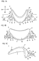
- a reflector of a vehicular headlamp according to a first embodiment will be described with reference to Figs. 1A to 1C .
- the reflector is an optical member for reflecting and controlling the light emitted from an LED light source.
- the vehicular headlamp is one of a vehicular lamp that is a light emitting device for a vehicle.
- Fig. 1A to Fig. 6 as shown in Fig.
- a direction of a reflective surface of a reflector body directly facing a lens and a rear direction of the reflective surface are referred to as "a front-rear direction (a direction of the reference signs Fr and Re)"
- a formation direction of an arm part formed integrally with the reflector body is referred to as "a left-right direction (a direction of the reference signs Le and Ri)”
- an extending direction of a mounting hole of the arm part is referred to as "an up-down direction (a direction of the reference signs Up and Lo)”.
- a reflector 1 according to the first embodiment includes a reflector body 2 made of resin and a pair of arm parts 3, 4 formed integrally with the reflector body 2.
- the resin reflector body 2 has a shape that is obtained by obliquely cutting a semi paraboloid of revolution forward from the rear. As a result, the reflector body 2 is opened to the front and has a substantially U shape, as seen from the upper surface.
- a reflective surface 5 configured by a portion of the paraboloid of revolution is formed by silver deposition or the like.
- Respective reflective surfaces 5, 26, 26' in the first embodiment and a second and third embodiment include a reflective region where light is incident and reflected and a region (where light is not incident) other than the reflective region.
- the reflector body 2 is provided with a rib 6 protruding in a horizontal direction, along a lower end portion 2b of an outer peripheral surface 2a thereof.
- Left and right front end portions 6a, 6b of the rib 6 are respectively provided at positions spaced rearward from front end portions 2c, 2d of the reflector body 2.
- the pair of arm parts 3, 4 is integrally provided in the outer peripheral surface 2a of the reflector body 2 so as to extend laterally from the vicinity of the front end portions 6a, 6b of the rib 6.
- circular holes 7, 8 serving as a fixation portion for a supporting member (not shown) are provided at positions that are located in the vicinity of rear ends 3a, 4a and spaced laterally from the outer peripheral surface 2a.
- the circular holes 7, 8 are penetrated in a vertical direction.
- the arm parts 3, 4 are respectively formed with gap portions 9, 10 serving as a thermal deformation absorbing portion (thermal expansion guiding portion).
- the gap portions 9, 10 are provided at boundary portions of the rib 6 and the arm parts 3, 4 in between the circular holes 7, 8.
- the reflector body or a shade (to be described later) is deformed by a lighting heat of a light emitting element. Thermal deformation such as thermal expansion occurring in the reflector body or the shade (to be described later) is absorbed by being guided by the thermal deformation absorbing portions.
- the gap portions 9, 10 are formed on the front along the lower end 2b of the reflector body 2 from the rear ends 3a, 4a of the arm parts.
- the gap portions 9, 10 are formed between the circular holes 7, 8 serving as a fixation portion and the reflective surface 5 including the reflective region.
- the reflector 1 is fixed to a supporting member in such a way that screw members (not shown) inserted into the circular holes 7, 8 are screwed to a reflector fixing portion of the supporting member (not shown) of a vehicular headlamp.
- the lateral clearances of the gap portions 9, 10 are narrowed when the reflector body 2 receives the heat of a light emitting element (not shown) from the supporting member and therefore is thermally deformed (thermally expanded). Therefore, the reflector body 2 can be thermally deformed laterally toward the fixation portion for the supporting member, i.e., toward the circular holes 7, 8.
- the reflector body 2 is thermally deformed in a lateral direction owing to the gap portions 9, 10, instead of being thermally deformed only in a vertical direction. Accordingly, both the reflector body 2 and the reflective surface 5 on the inside thereof are thermally deformed while keeping a bilaterally symmetric shape thereof. As a result, the reflective surface 5 forms a light distribution pattern that has a similar shape to a desired light distribution pattern and therefore a deformation of a light distribution pattern is prevented.
- the gap portions 9, 10 are preferably provided in the arm parts 3, 4 so that front end portions 9a, 10a thereof are substantially flush with or located in front of front end portions 7a, 8a of the circular holes 7, 8.
- the front end portions 9a, 10a of the gap portions 9, 10 are provided rearward of the front end portions 7a, 8a of the circular holes 7, 8 and therefore overlapped with the left and right regions of the circular holes 7, 8, there is a possibility that the reflector 1 is less likely to be thermally deformed laterally while keeping a similar shape thereto, in a portion of the arm parts 3, 4 located between the front end portions 7a, 8a of the circular holes 7, 8 and the outer peripheral surface 2a.
- the thermal deformation of the reflector body 2 in a lateral direction is less likely to be hindered and therefore a deformation of a light distribution pattern is further prevented.
- the arm parts 3, 4 and the rib 6 are preferably formed so that a longitudinal length L1 from the rear end portions 3a, 4a to the front end portions 6a, 6b of the rib 6 is sufficiently longer than a longitudinal direction L2 from the rear end portions 3a, 4a to the front end portions 9a, 10a of the gap portions 9, 10.
- L is twice as long or more than L2.
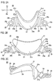
- a pair of left and right arm parts 22, 23 is provided with wave-shaped parts 24, 25 serving as a thermal deformation absorbing portion (thermal expansion guiding portion).
- the left and right arm parts 22, 23 are formed integrally with a reflector body 21 having the same shape as the reflector body 2 of the first embodiment, by a flexible resin (for example, resin such as Polycarbonate (PC), Polypropylene (PP), Polycarbonate-ABS (PC-ABS)).
- a reflective surface 26 configured by a portion of the paraboloid of revolution is formed by silver deposition or the like.
- the reflector body 21 is provided with a rib 27 protruding in a horizontal direction, along a lower end portion 21b of an outer peripheral surface 21a thereof. Left and right front end portions 27a, 27b of the rib 27 are respectively provided at positions spaced rearward from front end portions 21c, 21d of the reflector body 21.
- the pair of arm parts 22, 23 is integrally provided in the outer peripheral surface 21a of the reflector body 21 so as to extend laterally from the vicinity of the front end portions 27a, 27b of the rib 27.
- the wave-shaped parts 24, 25 serving as a thermal deformation absorbing portion are provided between the circular holes 28, 29 and the rib 27, respectively.
- Each of the left and right wave-shaped parts 24, 25 has a bellows shape in which convex portions 24a, 25a are continued while facing upward and downward, alternately. Further, the convex portions 24a, 25a are bent at bent portions 24b, 25b so that the convex portions are gradually flared forward from the rear along the lower end portion 21b of the outer peripheral surface 21a.
- the reflector 20 is fixed to a supporting member 38 of a vehicular headlamp 33 (to be described later) by screw members 44, 45 inserted into the circular holes 28, 29.
- Heat generated from a LED (light emitting element) 36 fixed to the supporting member 38 is transmitted to the reflector 20 via the supporting member 38.
- the reflector body 21 is thermally deformed laterally toward the circular holes 28, 29, owing to the contraction of the wave-shaped portions 24, 25 of the arm parts 22, 23.
- the thermal deformation of the reflector body 21 and the reflective surface 26 in a lateral direction is not hindered and therefore both the reflector body 21 and the reflective surface 26 on the inside thereof are thermally deformed while keeping a bilaterally symmetric shape thereof. Consequently, the reflective surface 26 forms a light distribution pattern that has a similar shape to a desired light distribution pattern and therefore a deformation of a light distribution pattern is prevented.
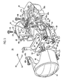
- the vehicular headlamp 33 includes the reflector 20, the LED (light emitting element) 36, a power feeding attachment 37 for attaching the LED 36 thereon, the resin supporting member 38, a movable shade unit 39, a lens holder 40 and a projection lens 41. Further, as shown in Fig. 4 , the projector type vehicular headlamp 33 is disposed in a lamp chamber S which is formed by a lamp body 34 that is opened forward and formed of resin or the like and a transparent or semi-transparent front cover 35 that closes the front of the lamp body 34. The projector type vehicular headlamp 33 is supported on the lamp body 34 by an aiming mechanism (tiling mechanism) which is not shown.
- aiming mechanism tilt mechanism
- the LED 36 is fixed to the supporting member 38 via the power feeding attachment 37.
- the power feeding attachment 37 is fixed to the supporting member 38 in a state where a rear surface of a substrate of the LED 36 is brought into contact with an upper surface 38a of the supporting member 38 by fitting a pair of protrusions 38b, 38c of the upper surface 38a into circular holes 37a, 37b of the power feeding attachment 37.
- a pair of reflector fixing portions 42, 43 is provided at positions corresponding to the circular holes 28, 29 in the pair of arm parts 22, 23 of the reflector 20.
- the reflector 20 is attached to the reflector fixing portions 42, 43 in such a way that a pair of screw members 44, 45 is inserted into the circular holes 28, 29 and screwed to female screw holes 42a, 43a provided on the inside of the reflector fixing portions 42, 43. As a result, the reflector 20 is fixed to the supporting member 38 in a state where the LED 36 is surrounded with the reflective surface 26.
- the movable shade unit 39 is disposed in front of the supporting member 38.
- the projection lens 41 attached to the lens holder 40 is disposed in front of the movable shade unit 39.
- the movable shade unit 39 and the lens holder 40 are fixed to the supporting member 38 in such a way that three screw members 46a to 46c are respectively inserted into circular holes 39a to 39c provided on an end portion of the movable shade unit 39 and circular holes 40a to 40c provided on the lens holder 40 and then screwed to female screw holes 48a, 49a (and the other one is not shown) of three fixation portions 48, 49 (and the other one is not shown) provided on a front end portion of the supporting member 38.
- the movable shade unit 39 includes a motor 51 attached to a supporting plate 50 with the circular holes 39a to 39, a gear 52 attached to a pivot shaft of the motor 51, an arm 53 which has one end pivotably attached to the supporting plate 50 and includes a gear meshed with the gear 52, a shade 56 which has one end pivotably attached to the other end of the arm 53 and includes a cutoff line forming portion 55 at an upper end thereof and, and a torsion coil spring 57.
- the shade 56 is urged to an upward positioning stopper (not shown) provided on the supporting plate 50 by the torsion coil spring 57 and the cutoff line forming portion 55 is disposed near a rear focal point S1 of the projection lens 41 while keeping a horizontal state thereof.
- the shade 56 shown in Fig. 3 is lowered to a position where the light emitted from the LED 36 is not shielded by the swinging of the arm 53 including the gear.
- the shade 56 lowered to the position where the shade does not shield the light emitted from the LED 36 is lifted by receiving an urging force of the torsion coil spring 57 when the power supply to the motor 51 is interrupted.
- the cutoff line forming portion 55 is returned to the vicinity of the rear focal point S1 of the projection lens 41.
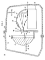
- the light B1 emitted from the LED 36 is reflected in the reflective surface 26 so that a focal point thereof is near the rear focal point S1 of the projection lens 41.
- the emitted light B1 passes through the projection lens 41 and the front cover 35 while a portion of the light is shielded by the cutoff line forming portion 55 of the shade 56, thereby forming a light distribution pattern for a lower beam in front of the vehicular headlamp 33.
- the emitted light B1 is not shielded by the shade 56, thereby forming a light distribution pattern for a high beam in front of the vehicular headlamp 33.
- the reflector 20 to be thermally deformed by the lighting heat of the LED 36 is thermally deformed while keeping a similar shape thereto owing to the contraction of the wave-shaped portions 24, 25 serving as the thermal deformation absorbing portion, a light distribution pattern without a deformation is formed in front of the vehicular headlamp 33.
- a reflector 60 of the third embodiment is obtained by forming a shade 61 in the reflector 20 of the second embodiment, instead of providing a movable shade unit 39 shown in Fig. 4 .
- the shade 61 and the reflector body 21' form the reflector 60 that is an optical member.
- the shade 61 has a plate-like shape and is formed integrally to an inner side of the reflector body 21'. Further, the shade 61 is formed to extend rearward along a lower end portion 21b' from front end portions 21c', 21d' of the reflector body 21'.
- a stepped cutoff line forming portion 62 is provided on an upper end of a front end portion 61a of the shade 61.
- the cutoff line forming portion 62 is disposed near a rear focal point of a projection lens (not shown).
- the reflector 60 of the third embodiment may be formed in such a way that the shade 61 and the reflector body 21' are separately formed and then the shade 61 is bonded to the reflector body 21' by a bonding means such as adhesion or thermal caulking.
- a reflective surface 63 is provided on an upper surface of the shade 61 by silver deposition or the like. Further, the shade 61 is respectively provided with a pair of gap portions 64, 65 serving as a thermal deformation absorbing portion.
- the pair of gap portions 64, 65 is formed on the shade 61 to extend rearward along a curved shape of the reflective surface 26' from the front end portion 61a, in the vicinity of both left and right end portions 61c, 61d of the shade 61.
- the reflective surface 63 of the shade 61 includes a reflective region 63a that is used for reflection of light and non-reflective regions 63b, 63c that are not used for reflection of light.
- the reflective region 63a is formed at a portion of the reflective surface 63 between an extending line Li1 passing through an inner edge 64a of the gap portion 64 and an extending line Li2 passing through an inner edge 65a of the gap portion 65.
- the non-reflective region 63b is formed on the outside of the extending line Li1 and the non-reflective region 63c is formed on the outside of the extending line Li2.
- the pair of gap portions 64, 65 is respectively formed in the non-reflective regions 63b, 63c of the reflective surface 63, the reflection of light in the reflective region 63a is not hindered and the deformation of a light distribution pattern does not occur.
- the light that is emitted from an LED (not shown) and reflected by the reflective surface 26' is focused in the vicinity of the cutoff line forming portion 62. Therefore, the light is emitted to the front of a vehicular headlamp from a projection lens and front cover (that are not shown) while a portion of the light is shielded by the cutoff line forming portion 62.
- the light shielded by the cutoff line forming portion 62 is re-reflected obliquely upward by the reflective surface 63 and then emitted to the front of a vehicular headlamp from a projection lens and front cover (that are not shown).
- the thermal deformation of the shade 61 of the reflector 60 is promoted freely in a lateral direction by the presence of the gap portions 64, 65 of the shade 61 and each contraction of a wave-shaped portion 24' of an arm part 22' and a wave-shaped portion (not shown) of an arm part 23'.
- the reflective surface 26' of the reflector body 21' and the shade 61 are thermally deformed while keeping a similar shape thereto, it is possible to form a light distribution pattern without a deformation.
- a reflector 70 of the fourth embodiment that is an optical member includes a plate-shape reflector body 71 formed to extend forward and backward and a pair of arm parts 72, 73 formed to extend laterally from a rear end portion 71a of the reflector body 71.
- the arm parts 72, 73 are provided with circular holes 74, 75 as a fixation portion (not shown) for the supporting member.
- the circular holes 74, 75 are penetrated in a vertical direction.
- a reflective surface 78 is formed on an upper surface of the reflector body 71 by silver deposition or the like.
- a stepped cutoff line forming portion 79 is formed on an upper end of a front end portion 71b of the reflector body 71 so as to be disposed near a rear focal point of a projection lens (not shown).
- the reflector body 71 also has a function as a shade.
- the reflective surface 78 of the reflector body 71 includes a reflective region 78a that is used for reflection of light and non-reflective regions 78b, 78c that are not used for reflection of light.
- the reflective region 78a is formed between an extending line Li3 passing through an inner end 76a of the gap portion 76 and an extending line Li4 passing through an inner end 77a of the gap portion 77.
- the non-reflective region 78b is formed on the outside of the extending line Li3 and the non-reflective region 78c is formed on the outside of the extending line Li4.
- the pair of gap portions 76, 77 is respectively formed in the non-reflective regions 78b, 78c of the reflective surface 78, the reflection of light in the reflective region 78a is not hindered and the deformation of a light distribution pattern does not occur.
- the light emitted from an LED (not shown) is emitted to the front of a vehicular headlamp from a projection lens and front cover (that are not shown) while a portion of the light is shielded by the cutoff line forming portion 79.
- the light shielded by the cutoff line forming portion 79 is re-reflected obliquely upward by the reflective surface 78 and then emitted to the front of a vehicular headlamp from a projection lens and front cover (that are not shown).
- the thermal deformation of the reflective surface 78 and the cutoff line forming portion 79 in the reflector body 71 is promoted freely in a lateral direction as well as in an upper direction by the gap portions 76, 77, the reflective surface 78 and the cutoff line forming portion 79 are thermally deformed while keeping a similar shape thereto. As a result, it is possible to form a light distribution pattern without a deformation.
- the arm part and the fixation portion are respectively provided in pairs in the reflectors of the first to fourth embodiments, the arm part and the fixation portion may be provided by only one or the arm part and the fixation part may be provided by three or more.
- an optical member 85 of a fifth embodiment including a lens holder with a shade and a reflector will be described with reference to Fig. 7A to Fig. 8B .
- a longitudinal direction of the optical member 85 is referred to as "a front-rear direction (a direction of the reference signs Fr and Re)"
- a width direction of the optical member 85 is referred to as "a left-right direction (a direction of the reference signs Le and Ri)”
- a height direction of the optical member 85 is referred to as "an up-down direction (a direction of the reference signs Up and Lo)”.
- the optical member 85 of the fifth embodiment includes a reflector 86 made of resin and a lens holder 87 having a shade 88.
- the reflector 86 is formed into a U shape, as seen from the upper surface and provided at its inner side with a reflective surface 89 configured by a portion of the paraboloid of revolution.
- the reflector 86 is fixed to the lens holder 87.
- the lens holder 87 includes a lens holding part 91 and a reflector holding part 92.
- the lens holding part 91 is provided continuously to a front end portion 92a of the reflector holding part 92.
- the lens holding part 91 is provided at its center with an attachment hole 91a to which a projection lens (not shown) of a semi-spherical shape is attached.
- the reflector holding part 92 includes a pair of circular holes 93, 94 that is a fixation portion provided near the front end portion 92a thereof, a pair of circular holes (not shown) for thermal caulking that is provided near a rear end portion 92b thereof and a light passing portion 95 for passing the reflected light therethrough.
- the circular holes 93, 94 are penetrated in a vertical direction and the light passing portion 95 is provided on the inside of the pair of circular holes 93, 94.
- a pair of protrusions (not shown) provided in the reflector 86 is inserted into the pair of circular holes (not shown) for thermal caulking. A leading end of the pair of protrusions is crushed by application of heat and therefore formed as thermal caulking portions 90a, 90b.
- the reflector 86 is fixed to the lens holder 87 by the thermal caulking portions 90a, 90b.
- the shade 88 is provided between a region having the circular holes 93, 94 formed thereon and the thermal caulking portions 90a, 90b, in the reflector holding part 92.
- the shade 88 includes a shade body 97, a cutoff line forming portion 98 and a pair of gap portions 99, 100 that is a thermal deformation absorbing portion.
- the shade body 97 has a reflective surface (a rear surface of the shade body 97 in Fig. 8 B) facing the reflective surface 89 of the reflector 86.
- the cutoff line forming portion 98 is provided in a front end portion of the shade body 97 and has a shape similar to an arc that is concave from the front to the rear.
- the cutoff line forming portion 98 is disposed near a rear focal point of a projection lens (not shown) that is attached to the lens holding part 91.
- the gap portion 99 is formed on the non-reflective region 97b located between the reflective region 97a and an end of the circular hole 93 serving as a fixation portion.
- the gap portion 100 is formed in the non-reflective region 97c located between the reflective region 97a and the circular hole 94.
- the reflector 86 fixed to the supporting member is deformed by receiving heat from an LED light source at the time of lighting of the LED light source (not shown) similarly fixed to the supporting member.
- the shade body 97 and the reflective region 97a are deformed while keeping a similar shape thereto by allowing the gap portions 99, 100 provided on the outside of the reflective region 97a to absorb deformation, the deformation of a light distribution pattern does not occur.
- the gap portions 99, 100 are formed in the non-reflective regions 97b, 97c on the inside between the circular holes 93, 94, the gap portions does not hinder the re-reflection of the reflected light by the shade body 97. That is, the reflected light by the reflector is not lost through the circular holes 93, 94.
- the gap portions and the wave-shaped portions (thermal deformation absorbing portions) in the first to fifth embodiments may be formed at arbitrary positions of a non-reflective region that exists between the fixation portion and the reflective region.
- the lamp unit 104 includes the optical member 85 having the reflector 86 and the metallic supporting member 105 on which both a light emitting element serving as a light source and the optical member 85 are held.
- the reflector 86 is formed of resin and has a reflective region.
- a plurality of radiation fins 109 extending in a direction away from the reflector 86 is provided in the supporting member 105 so as to be arranged beside the reflector 86.
- the supporting member 105 includes a holding part 106 for the optical member 85, a pair of attachment parts 107, 108 formed to extend laterally from the holding part 106 and a plurality of radiation fins 109 formed to extend rearward of the holding part.
- fixation holes are provided at positions corresponding to the circular holes 93, 94 serving as a fixation portion of the optical member 85 and the reflector holding part 92 of the optical member 85 is mounted thereon.
- the optical member 85 is fixed to the upper portion 106a of the holding part 106 in such a way that fastening members (not shown) such as bolts are inserted through the circular holes 93, 94 and the fixation holes of the holding part 106 side and mounted to female screw holes provided on holes (not shown) of the holding part 106.
- the lamp unit is fixed to a lamp body (not shown) or the like by the fastening of fastening members such as bolts through a plurality of circular holes 107a (a circular hole of the attachment part 108 is not shown) of the attachment parts 107, 108.
- the plurality of radiation fins 109 has a flat plate shape, respectively and extends rearward of the holding part 106.
- the plurality of flat plate-shaped radiation fins 109 is extended further upward from the rear of the holding part 106 and arranged beside the reflector 86, respectively.
- the plurality of flat plate-shaped radiation fins 109 is arranged to be parallel to each other.
- a portion of heat generated at the time of lighting of the light emitting element in the lamp unit 104 is discharged from the radiation fins 109 of the metallic supporting member 105 or transmitted to the reflector 86 to raise the temperature of the reflector 86.
- the plurality of radiation fins 109 has a function to pass the air (whose temperature is raised in conjunction with the temperature of the reflector 86) around the reflector 86 through between adjacent radiation fins 109, thereby causing the air to flow in a direction away from the reflector 86. Further, the plurality of radiation fins 109 has an effect of reducing the thermal deformation of the reflector 86 due to the temperature rise, since hot air is not stayed around the reflector 86 owing to the radiation fins.
- the flat plate-shaped radiation fins 109 shown in Fig. 9 may be formed to extend laterally or obliquely rearward from the reflector, as long as the flat plate-shaped radiation fins are composed of a plurality of plate-shaped parts extending in a direction away from the reflector 86.
Landscapes
- Engineering & Computer Science (AREA)
- General Engineering & Computer Science (AREA)
- Non-Portable Lighting Devices Or Systems Thereof (AREA)
Abstract
Description
- The present disclosure relates to an optical member and a vehicular lamp, which prevent the deformation of a light distribution pattern due to the fact that the optical member is thermally deformed by a lighting heat of a light emitting element.
-
Patent Document 1 discloses a projector type vehicular lamp for forming a light distribution pattern on the front of a vehicle in such a way that the light emitted from an LED that is a light source is reflected by a reflector. In the projector type vehicular lamp disclosed inPatent Document 1, the LED fixed to an attachment plate is disposed so that the LED is screwed to an upper reflector having a small concave mirror (reflective surface) of a spheroidal curved surface shape and therefore the LED is surrounded with the small concave mirror of the upper reflector. The upper reflector having the LED fixed thereto constitutes a small reflector together with a lower reflector in such a way that a flange portion thereof is screwed to the lower reflector. The small reflector is fixed to a casing by being screwed to an attachment tool (supporting member), as described in paragraph [0045] andFig. 3 andFig. 4 ofPatent Document 1. - Patent Document 1: Japanese Patent Laid-Open Publication No.
2005-209604 - Since the upper reflector of the projector type vehicular lamp disclosed in
Patent Document 1 is formed of resin and connected to the LED via the attachment plate, the upper reflector is thermally expanded by receiving heat from the LED during lighting. The thermal expansion of the upper reflector becomes greater as the size of the small reflector is reduced with the miniaturization of the projector type vehicular lamp. The thermal expansion of the small reflector having received heat is restricted in a lateral direction when flange portions formed integrally to the left and right thereof are fixed to an attachment portion. As a result, the small reflector having received heat is thermally expanded toward the upper side that is not fixed, together with the small concave mirror (reflective surface) and therefore the small concave mirror is thermally deformed to an unexpected shape. The thermal deformation of the small concave mirror causes the deformation of a light distribution pattern. - Exemplary embodiments of the invention provide an optical member and a vehicular lamp, in which the deformation of a light distribution pattern is difficult to occur, even when the optical member such as a reflector or shade is thermally deformed by heat generated at the time of lighting of a light emitting element.
- An optical member formed of resin, according to an exemplary embodiment of the invention, comprises
a fixation portion for fixing the optical member to a supporting member on which a light emitting element is supported;
a reflective surface having a reflective region configured to reflect light from the light emitting element; and
a thermal deformation absorbing portion configured to absorb thermal deformation of the optical member. - The thermal deformation absorbing portion absorbs the thermal deformation of the optical member at the time of lighting of the light emitting element. Therefore, it is likely that the optical member will be able to be thermally deformed while keeping a similar shape to the reflective region. As a result, the light distribution pattern is likely to have a similar shape to a desired light distribution pattern.
- The thermal deformation absorbing portion may be formed at a portion other than the reflective region.
- Since the thermal deformation absorbing portion is less likely to hinder the reflection of light to be incident on the reflective region, the desired light distribution pattern shape can be easily obtained.
- The optical member may further comprise:
- a reflector body including the reflective surface, and
- an arm part formed to extend from the reflector body, wherein
- the fixation portion and the thermal deformation absorbing portion are provided in the arm part.
- The reflector body having the reflective region is fixed to the supporting member by the fixation portion of the arm part extending from the reflector body.
- Owing to the thermal deformation absorbing portion, the arm part fixed to the supporting member via the fixation portion is deformed so as not to hinder the free thermal deformation of the reflector body. As a result, the reflector body is thermally deformed while keeping a similar shape thereto and therefore the light distribution pattern is more likely to have a similar shape to the desired light distribution pattern.
- The thermal deformation absorbing portion may be provided between the reflective region and the fixation portion.
- The optical member having received the heat generated at the time of lighting of a light emitting element (hereinafter referred as a lighting heat of the light emitting element) tends to be thermally deformed toward the fixation portion, together with the reflective region. However, since the optical member and the reflective region are thermally deformed while keeping the similar shape thereto, owing to the thermal deformation absorbing portion provided between the fixation portion and the reflective region, the light distribution pattern having a similar shape to the desired light distribution pattern is likely to be formed.
- The thermal deformation absorbing portion may be or comprise a gap portion.
- The thermal deformation absorbing portion that is a gap portion is thermally deformed together with the reflective region while keeping the similar shape thereto in such a way that the gap portion is narrowed by the thermal expansion of the optical member. As a result, the light distribution pattern having a similar shape to the desired light distribution pattern is likely to be formed.
- The thermal deformation absorbing portion may be or comprise a wave-shaped portion.
- The wave-shaped portion absorbs the thermal deformation of the optical member by being expanded/contracted due to the thermal deformation of the optical member and therefore both the optical member and the reflective region are deformed in a state of keeping a bilaterally symmetric shape thereof. Accordingly, the light distribution pattern having a similar shape to the desired light distribution pattern is likely to be formed.
- The optical member may further comprise:
- a shade arranged near a focal point that is focused forward by a light reflected from the reflective region and configured to shield a portion of the reflected light.
- The optical member including the shade is thermally deformed while keeping a similar shape thereto, owing to the thermal deformation absorbing portion. As a result, the relative position of the cutoff line to be formed by the shade is not lowered and therefore the light distribution pattern having a similar shape to the desired light distribution pattern is likely to be formed.
- The shade may include a thermal deformation absorbing portion different from the thermal deformation absorbing portion of the arm part.
- Since the thermal deformation of the shade is absorbed by the thermal deformation absorbing portion, the shade is likely to be deformed in a state of keeping a similar shape thereto. As a result, the relative position of the cutoff line to be formed by the shade is not lowered and therefore the light distribution pattern having a similar shape to the desired light distribution pattern is more likely to be formed.
- The shade may include a reflective region configured to reflect the light reflected from the reflective region of the reflector body, and
in the shade, the thermal deformation absorbing portion is provided at a region other than the reflective region.
The optical member may further comprise: - a shade configured to shield a portion of the light from the light emitting element, the shade including the reflective surface and the thermal deformation absorbing portion, wherein
- the thermal deformation absorbing portion is provided at a region other than the reflective region.
- Since the thermal deformation absorbing portion provided in the shade is less likely to hinder the reflection of light to be incident on the reflective region, the desired light distribution pattern can be easily obtained.
- A vehicular lamp according to an exemplary embodiment of the invention comprises:
- a light emitting element;
- the optical member described above; and
- a supporting member on which the light emitting element and the optical member are supported,
- wherein the light emitting element, the optical member and the supporting member are provided in a lamp chamber formed by a front cover and a lamp body.
- Since the optical member is likely to be thermally deformed while keeping a similar shape to the reflective region, the light distribution pattern to be formed in the vehicular lamp is likely to have a similar shape to the desired light distribution pattern.
- According to the optical member and the vehicular lamp, the light distribution pattern having a similar shape to the desired light distribution pattern is likely to be formed even when the reflective region is deformed by the thermal deformation of the optical member. Accordingly, it is possible to obtain a light distribution pattern in which the deformation is reduced.
- According to the optical member and the vehicular lamp, the light to be incident on the reflective region is reflected appropriately without being hindered by the thermal deformation absorbing portion. Accordingly, it is possible to obtain a light distribution pattern in which the deformation is further reduced.
- According to the optical member and the vehicular lamp, the relative position of the cutoff line to be formed by the shade is not lowered and therefore it is possible to obtain a light distribution pattern in which the deformation is further reduced.
-
-
Fig. 1A is a plan view showing a reflector of a vehicular headlamp according to a first embodiment. -
Fig. 1B is a perspective view of the reflector in the first embodiment, as seen obliquely from the rear upper side. -
Fig. 1C is a perspective view of the reflector in the first embodiment, as seen obliquely from the left upper side. -
Fig. 2A is a plan view showing a reflector of a vehicular headlamp according to a second embodiment. -
Fig. 2B is a perspective view of the reflector in the second embodiment, as seen obliquely from the rear upper side. -
Fig. 2C is a perspective view of the reflector in the second embodiment, as seen obliquely from the left upper side. -
Fig. 3 is an exploded perspective view of a vehicular headlamp mounted with the reflector of the second embodiment. -
Fig. 4 is an explanatory view for explaining a ray of light in the projector type vehicular headlamp shown inFig. 3 . -
Fig. 5 is a perspective view of a reflector according to a third embodiment, which is integrally provided with a shade. -
Fig. 6 is a perspective view of a reflector according to a fourth embodiment, in which a reflector body serves as a shade. -
Fig. 7A is a perspective view of an optical member according to a fifth embodiment, which includes a lens holder with a shade and a reflector. -
Fig. 7B is a left side view of the optical member according to the fifth embodiment. -
Fig. 8A is a plan view of the optical member according to the fifth embodiment. -
Fig. 8B is a bottom view of the optical member according to the fifth embodiment. -
Fig. 9 is a perspective view showing a sixth embodiment, in which a lamp unit is formed by fixing the optical member according to the fifth embodiment to a supporting member. - A reflector of a vehicular headlamp according to a first embodiment will be described with reference to
Figs. 1A to 1C . The reflector is an optical member for reflecting and controlling the light emitted from an LED light source. The vehicular headlamp is one of a vehicular lamp that is a light emitting device for a vehicle. InFig. 1A to Fig. 6 , as shown inFig. 1A , a direction of a reflective surface of a reflector body directly facing a lens and a rear direction of the reflective surface are referred to as "a front-rear direction (a direction of the reference signs Fr and Re)", a formation direction of an arm part formed integrally with the reflector body is referred to as "a left-right direction (a direction of the reference signs Le and Ri)" and an extending direction of a mounting hole of the arm part is referred to as "an up-down direction (a direction of the reference signs Up and Lo)". - A
reflector 1 according to the first embodiment includes areflector body 2 made of resin and a pair ofarm parts reflector body 2. Theresin reflector body 2 has a shape that is obtained by obliquely cutting a semi paraboloid of revolution forward from the rear. As a result, thereflector body 2 is opened to the front and has a substantially U shape, as seen from the upper surface. At an inner side of thereflector body 2, areflective surface 5 configured by a portion of the paraboloid of revolution is formed by silver deposition or the like. Respectivereflective surfaces - The
reflector body 2 is provided with arib 6 protruding in a horizontal direction, along alower end portion 2b of an outerperipheral surface 2a thereof. Left and rightfront end portions rib 6 are respectively provided at positions spaced rearward fromfront end portions reflector body 2. The pair ofarm parts peripheral surface 2a of thereflector body 2 so as to extend laterally from the vicinity of thefront end portions rib 6. At left and right ends 3b, 4b of the pair ofarm parts circular holes rear ends peripheral surface 2a. Thecircular holes - The
arm parts gap portions gap portions rib 6 and thearm parts circular holes gap portions lower end 2b of thereflector body 2 from therear ends gap portions circular holes reflective surface 5 including the reflective region. - The
reflector 1 is fixed to a supporting member in such a way that screw members (not shown) inserted into thecircular holes - The lateral clearances of the
gap portions reflector body 2 receives the heat of a light emitting element (not shown) from the supporting member and therefore is thermally deformed (thermally expanded). Therefore, thereflector body 2 can be thermally deformed laterally toward the fixation portion for the supporting member, i.e., toward thecircular holes reflector body 2 is thermally deformed in a lateral direction owing to thegap portions reflector body 2 and thereflective surface 5 on the inside thereof are thermally deformed while keeping a bilaterally symmetric shape thereof. As a result, thereflective surface 5 forms a light distribution pattern that has a similar shape to a desired light distribution pattern and therefore a deformation of a light distribution pattern is prevented. - The
gap portions arm parts front end portions front end portions circular holes front end portions gap portions front end portions circular holes circular holes reflector 1 is less likely to be thermally deformed laterally while keeping a similar shape thereto, in a portion of thearm parts front end portions circular holes peripheral surface 2a. In a case where thefront end portions gap portions front end portions circular holes reflector body 2 in a lateral direction is less likely to be hindered and therefore a deformation of a light distribution pattern is further prevented. - Further, in order to maintain the strength of connecting
regions rib 6 and thearm parts arm parts rib 6 are preferably formed so that a longitudinal length L1 from therear end portions front end portions rib 6 is sufficiently longer than a longitudinal direction L2 from therear end portions front end portions gap portions - Next, a reflector of a vehicular headlamp according to a second embodiment will be described with reference to
Figs. 2A to 2C . - In a
reflector 20 of the second embodiment, a pair of left andright arm parts parts right arm parts reflector body 21 having the same shape as thereflector body 2 of the first embodiment, by a flexible resin (for example, resin such as Polycarbonate (PC), Polypropylene (PP), Polycarbonate-ABS (PC-ABS)). At an inner side of thereflector body 21, areflective surface 26 configured by a portion of the paraboloid of revolution is formed by silver deposition or the like. - The
reflector body 21 is provided with arib 27 protruding in a horizontal direction, along alower end portion 21b of an outerperipheral surface 21a thereof. Left and rightfront end portions rib 27 are respectively provided at positions spaced rearward fromfront end portions reflector body 21. The pair ofarm parts peripheral surface 21a of thereflector body 21 so as to extend laterally from the vicinity of thefront end portions rib 27. At left and right ends 22b, 23b of the pair ofarm parts holes rear ends peripheral surface 21a. - At the left and
right arm parts parts circular holes rib 27, respectively. Each of the left and right wave-shapedparts convex portions convex portions bent portions lower end portion 21b of the outerperipheral surface 21a. - As shown in
Fig. 3 , thereflector 20 is fixed to a supportingmember 38 of a vehicular headlamp 33 (to be described later) byscrew members circular holes member 38 is transmitted to thereflector 20 via the supportingmember 38. When thereflector body 21 is subjected to the heat generated from the LED, thereflector body 21 is thermally deformed laterally toward thecircular holes portions arm parts reflector body 21 and thereflective surface 26 in a lateral direction is not hindered and therefore both thereflector body 21 and thereflective surface 26 on the inside thereof are thermally deformed while keeping a bilaterally symmetric shape thereof. Consequently, thereflective surface 26 forms a light distribution pattern that has a similar shape to a desired light distribution pattern and therefore a deformation of a light distribution pattern is prevented. - Next, a projector type vehicular headlamp 33 including the
reflector 20 of the second embodiment will be described with reference toFig. 3 andFig. 4 . The vehicular headlamp 33 includes thereflector 20, the LED (light emitting element) 36, apower feeding attachment 37 for attaching theLED 36 thereon, theresin supporting member 38, amovable shade unit 39, alens holder 40 and aprojection lens 41. Further, as shown inFig. 4 , the projector type vehicular headlamp 33 is disposed in a lamp chamber S which is formed by alamp body 34 that is opened forward and formed of resin or the like and a transparent or semi-transparentfront cover 35 that closes the front of thelamp body 34. The projector type vehicular headlamp 33 is supported on thelamp body 34 by an aiming mechanism (tiling mechanism) which is not shown. - The
LED 36 is fixed to the supportingmember 38 via thepower feeding attachment 37. Thepower feeding attachment 37 is fixed to the supportingmember 38 in a state where a rear surface of a substrate of theLED 36 is brought into contact with anupper surface 38a of the supportingmember 38 by fitting a pair ofprotrusions upper surface 38a intocircular holes power feeding attachment 37. Further, at theupper surface 38a of the supportingmember 38, a pair ofreflector fixing portions circular holes arm parts reflector 20. Thereflector 20 is attached to thereflector fixing portions screw members circular holes female screw holes reflector fixing portions reflector 20 is fixed to the supportingmember 38 in a state where theLED 36 is surrounded with thereflective surface 26. - The
movable shade unit 39 is disposed in front of the supportingmember 38. Theprojection lens 41 attached to thelens holder 40 is disposed in front of themovable shade unit 39. Themovable shade unit 39 and thelens holder 40 are fixed to the supportingmember 38 in such a way that threescrew members 46a to 46c are respectively inserted intocircular holes 39a to 39c provided on an end portion of themovable shade unit 39 andcircular holes 40a to 40c provided on thelens holder 40 and then screwed tofemale screw holes fixation portions 48, 49 (and the other one is not shown) provided on a front end portion of the supportingmember 38. - The
movable shade unit 39 includes amotor 51 attached to a supportingplate 50 with thecircular holes 39a to 39, agear 52 attached to a pivot shaft of themotor 51, anarm 53 which has one end pivotably attached to the supportingplate 50 and includes a gear meshed with thegear 52, ashade 56 which has one end pivotably attached to the other end of thearm 53 and includes a cutoffline forming portion 55 at an upper end thereof and, and atorsion coil spring 57. - In a case where power is not supplied to the
motor 51, theshade 56 is urged to an upward positioning stopper (not shown) provided on the supportingplate 50 by thetorsion coil spring 57 and the cutoffline forming portion 55 is disposed near a rear focal point S1 of theprojection lens 41 while keeping a horizontal state thereof. In a case where power is supplied to themotor 51, theshade 56 shown inFig. 3 is lowered to a position where the light emitted from theLED 36 is not shielded by the swinging of thearm 53 including the gear. Theshade 56 lowered to the position where the shade does not shield the light emitted from theLED 36 is lifted by receiving an urging force of thetorsion coil spring 57 when the power supply to themotor 51 is interrupted. At this time, the cutoffline forming portion 55 is returned to the vicinity of the rear focal point S1 of theprojection lens 41. - As shown in
Fig. 4 , the light B1 emitted from theLED 36 is reflected in thereflective surface 26 so that a focal point thereof is near the rear focal point S1 of theprojection lens 41. In a case where the power supply to themotor 51 is interrupted, the emitted light B1 passes through theprojection lens 41 and thefront cover 35 while a portion of the light is shielded by the cutoffline forming portion 55 of theshade 56, thereby forming a light distribution pattern for a lower beam in front of the vehicular headlamp 33. Meanwhile, in a case where power is supplied to themotor 51, the emitted light B1 is not shielded by theshade 56, thereby forming a light distribution pattern for a high beam in front of the vehicular headlamp 33. - Since the
reflector 20 to be thermally deformed by the lighting heat of theLED 36 is thermally deformed while keeping a similar shape thereto owing to the contraction of the wave-shapedportions - Next, a reflector of a third embodiment having a shade integrally provided therewith will be described with reference to
Fig. 5 . Areflector 60 of the third embodiment is obtained by forming ashade 61 in thereflector 20 of the second embodiment, instead of providing amovable shade unit 39 shown inFig. 4 . Theshade 61 and the reflector body 21' form thereflector 60 that is an optical member. Theshade 61 has a plate-like shape and is formed integrally to an inner side of the reflector body 21'. Further, theshade 61 is formed to extend rearward along alower end portion 21b' fromfront end portions 21c', 21d' of the reflector body 21'. A stepped cutoffline forming portion 62 is provided on an upper end of afront end portion 61a of theshade 61. The cutoffline forming portion 62 is disposed near a rear focal point of a projection lens (not shown). In addition, thereflector 60 of the third embodiment may be formed in such a way that theshade 61 and the reflector body 21' are separately formed and then theshade 61 is bonded to the reflector body 21' by a bonding means such as adhesion or thermal caulking. - A
reflective surface 63 is provided on an upper surface of theshade 61 by silver deposition or the like. Further, theshade 61 is respectively provided with a pair ofgap portions gap portions shade 61 to extend rearward along a curved shape of the reflective surface 26' from thefront end portion 61a, in the vicinity of both left andright end portions shade 61. - As shown in
Fig. 5 , thereflective surface 63 of theshade 61 includes areflective region 63a that is used for reflection of light andnon-reflective regions reflective region 63a is formed at a portion of thereflective surface 63 between an extending line Li1 passing through an inner edge 64a of thegap portion 64 and an extending line Li2 passing through aninner edge 65a of thegap portion 65. Further, thenon-reflective region 63b is formed on the outside of the extending line Li1 and thenon-reflective region 63c is formed on the outside of the extending line Li2. Since the pair ofgap portions non-reflective regions reflective surface 63, the reflection of light in thereflective region 63a is not hindered and the deformation of a light distribution pattern does not occur. - The light that is emitted from an LED (not shown) and reflected by the reflective surface 26' is focused in the vicinity of the cutoff
line forming portion 62. Therefore, the light is emitted to the front of a vehicular headlamp from a projection lens and front cover (that are not shown) while a portion of the light is shielded by the cutoffline forming portion 62. The light shielded by the cutoffline forming portion 62 is re-reflected obliquely upward by thereflective surface 63 and then emitted to the front of a vehicular headlamp from a projection lens and front cover (that are not shown). The thermal deformation of theshade 61 of thereflector 60 is promoted freely in a lateral direction by the presence of thegap portions shade 61 and each contraction of a wave-shaped portion 24' of an arm part 22' and a wave-shaped portion (not shown) of an arm part 23'. As a result, since the reflective surface 26' of the reflector body 21' and theshade 61 are thermally deformed while keeping a similar shape thereto, it is possible to form a light distribution pattern without a deformation. - Next, a reflector of a fourth embodiment in which a reflector body serves as a shade will be described with reference to
Fig. 6 . Areflector 70 of the fourth embodiment that is an optical member includes a plate-shape reflector body 71 formed to extend forward and backward and a pair ofarm parts rear end portion 71a of thereflector body 71. Thearm parts circular holes - A pair of
gap portions arm parts 72, 73) in between thecircular holes gap portions reflector body 71 or thearm parts rear end portion 71a (orrear end portions arm parts 72, 73) of thereflector body 71. - A
reflective surface 78 is formed on an upper surface of thereflector body 71 by silver deposition or the like. In addition, a stepped cutoffline forming portion 79 is formed on an upper end of afront end portion 71b of thereflector body 71 so as to be disposed near a rear focal point of a projection lens (not shown). As a result, thereflector body 71 also has a function as a shade. - As shown in
Fig. 6 , thereflective surface 78 of thereflector body 71 includes areflective region 78a that is used for reflection of light andnon-reflective regions reflective region 78a is formed between an extending line Li3 passing through aninner end 76a of thegap portion 76 and an extending line Li4 passing through aninner end 77a of thegap portion 77. Thenon-reflective region 78b is formed on the outside of the extending line Li3 and thenon-reflective region 78c is formed on the outside of the extending line Li4. Since the pair ofgap portions non-reflective regions reflective surface 78, the reflection of light in thereflective region 78a is not hindered and the deformation of a light distribution pattern does not occur. - The light emitted from an LED (not shown) is emitted to the front of a vehicular headlamp from a projection lens and front cover (that are not shown) while a portion of the light is shielded by the cutoff
line forming portion 79. The light shielded by the cutoffline forming portion 79 is re-reflected obliquely upward by thereflective surface 78 and then emitted to the front of a vehicular headlamp from a projection lens and front cover (that are not shown). Since the thermal deformation of thereflective surface 78 and the cutoffline forming portion 79 in thereflector body 71 is promoted freely in a lateral direction as well as in an upper direction by thegap portions reflective surface 78 and the cutoffline forming portion 79 are thermally deformed while keeping a similar shape thereto. As a result, it is possible to form a light distribution pattern without a deformation. - Although the arm part and the fixation portion are respectively provided in pairs in the reflectors of the first to fourth embodiments, the arm part and the fixation portion may be provided by only one or the arm part and the fixation part may be provided by three or more.
- Next, an
optical member 85 of a fifth embodiment including a lens holder with a shade and a reflector will be described with reference toFig. 7A to Fig. 8B . - In
Fig. 7A to Fig. 9 , a longitudinal direction of theoptical member 85 is referred to as "a front-rear direction (a direction of the reference signs Fr and Re)", a width direction of theoptical member 85 is referred to as "a left-right direction (a direction of the reference signs Le and Ri)" and a height direction of theoptical member 85 is referred to as "an up-down direction (a direction of the reference signs Up and Lo)". - The
optical member 85 of the fifth embodiment includes areflector 86 made of resin and alens holder 87 having ashade 88. Thereflector 86 is formed into a U shape, as seen from the upper surface and provided at its inner side with areflective surface 89 configured by a portion of the paraboloid of revolution. Thereflector 86 is fixed to thelens holder 87. - The
lens holder 87 includes alens holding part 91 and areflector holding part 92. Thelens holding part 91 is provided continuously to afront end portion 92a of thereflector holding part 92. Thelens holding part 91 is provided at its center with anattachment hole 91a to which a projection lens (not shown) of a semi-spherical shape is attached. - The
reflector holding part 92 includes a pair ofcircular holes front end portion 92a thereof, a pair of circular holes (not shown) for thermal caulking that is provided near arear end portion 92b thereof and alight passing portion 95 for passing the reflected light therethrough. The circular holes 93, 94 are penetrated in a vertical direction and thelight passing portion 95 is provided on the inside of the pair ofcircular holes reflector 86 is inserted into the pair of circular holes (not shown) for thermal caulking. A leading end of the pair of protrusions is crushed by application of heat and therefore formed asthermal caulking portions reflector 86 is fixed to thelens holder 87 by thethermal caulking portions - The
shade 88 is provided between a region having thecircular holes thermal caulking portions reflector holding part 92. Theshade 88 includes ashade body 97, a cutoffline forming portion 98 and a pair ofgap portions shade body 97 has a reflective surface (a rear surface of theshade body 97 inFig. 8 B) facing thereflective surface 89 of thereflector 86. The cutoffline forming portion 98 is provided in a front end portion of theshade body 97 and has a shape similar to an arc that is concave from the front to the rear. The cutoffline forming portion 98 is disposed near a rear focal point of a projection lens (not shown) that is attached to thelens holding part 91. - The pair of
gap portions shade body 97. InFig. 8 B , the reflective surface formed on a rear surface of theshade body 97 includes areflective region 97a that is used for reflection of light andnon-reflective regions reflective region 97a is formed between an extending line Li5 passing through aninner end 99a of thegap portion 99 and an extending line Li6 passing through aninner end 100a of thegap portion 100. Thenon-reflective region 97b is formed on the outside of the extending line Li5 and thenon-reflective region 97c is formed on the outside of the extending line Li6. Thegap portion 99 is formed on thenon-reflective region 97b located between thereflective region 97a and an end of thecircular hole 93 serving as a fixation portion. Thegap portion 100 is formed in thenon-reflective region 97c located between thereflective region 97a and thecircular hole 94. - Light from an LED light source (not shown) is reflected toward the
shade 88 by thereflective surface 89 of thereflector 86. A portion of the reflected light is incident on the projection lens in front through thelight passing portion 95 from the cutoffline forming portion 98 and the other portion of the reflected light is incident on the projection lens by being re-reflected forward by thereflective region 97a of theshade body 97. The light incident on the projection lens is emitted forward of the projection lens and forms a light distribution pattern based on the shape of the cutoffline forming portion 98. - The
reflector 86 fixed to the supporting member is deformed by receiving heat from an LED light source at the time of lighting of the LED light source (not shown) similarly fixed to the supporting member. However, since theshade body 97 and thereflective region 97a are deformed while keeping a similar shape thereto by allowing thegap portions reflective region 97a to absorb deformation, the deformation of a light distribution pattern does not occur. Further, since thegap portions non-reflective regions circular holes shade body 97. That is, the reflected light by the reflector is not lost through thecircular holes - The gap portions and the wave-shaped portions (thermal deformation absorbing portions) in the first to fifth embodiments may be formed at arbitrary positions of a non-reflective region that exists between the fixation portion and the reflective region.
- Next, a sixth embodiment regarding a
lamp unit 104 that is formed by fixing theoptical member 85 to a metallic supportingmember 105 will be described with reference toFig. 9 . - The
lamp unit 104 includes theoptical member 85 having thereflector 86 and the metallic supportingmember 105 on which both a light emitting element serving as a light source and theoptical member 85 are held. Thereflector 86 is formed of resin and has a reflective region. A plurality ofradiation fins 109 extending in a direction away from thereflector 86 is provided in the supportingmember 105 so as to be arranged beside thereflector 86. - A specific configuration of the
lamp unit 104 is as follows. The supportingmember 105 includes a holdingpart 106 for theoptical member 85, a pair ofattachment parts part 106 and a plurality ofradiation fins 109 formed to extend rearward of the holding part. - At an
upper portion 106a of the holdingpart 106, fixation holes (not shown) are provided at positions corresponding to thecircular holes optical member 85 and thereflector holding part 92 of theoptical member 85 is mounted thereon. Theoptical member 85 is fixed to theupper portion 106a of the holdingpart 106 in such a way that fastening members (not shown) such as bolts are inserted through thecircular holes part 106 side and mounted to female screw holes provided on holes (not shown) of the holdingpart 106. The lamp unit is fixed to a lamp body (not shown) or the like by the fastening of fastening members such as bolts through a plurality ofcircular holes 107a (a circular hole of theattachment part 108 is not shown) of theattachment parts - In
Fig. 9 , the plurality ofradiation fins 109 has a flat plate shape, respectively and extends rearward of the holdingpart 106. The plurality of flat plate-shapedradiation fins 109 is extended further upward from the rear of the holdingpart 106 and arranged beside thereflector 86, respectively. The plurality of flat plate-shapedradiation fins 109 is arranged to be parallel to each other. - A portion of heat generated at the time of lighting of the light emitting element in the
lamp unit 104 is discharged from theradiation fins 109 of the metallic supportingmember 105 or transmitted to thereflector 86 to raise the temperature of thereflector 86. The plurality ofradiation fins 109 has a function to pass the air (whose temperature is raised in conjunction with the temperature of the reflector 86) around thereflector 86 through betweenadjacent radiation fins 109, thereby causing the air to flow in a direction away from thereflector 86. Further, the plurality ofradiation fins 109 has an effect of reducing the thermal deformation of thereflector 86 due to the temperature rise, since hot air is not stayed around thereflector 86 owing to the radiation fins. - Specifically, as shown in
Fig. 9 , air warmed near an outer peripheral surface of thereflector 86 flows toward theradiation fins 109 on the rear side along the outer peripheral surface of the reflector 86 (see a reference sign W1). Then, the air passes through the plurality ofradiation fins 109 without staying in the vicinity of arear end portion 86a of thereflector 86 and then is discharged further rearward of the radiation fins 109 (see a reference sign W2). - In addition, although a plurality of flat plate-shaped
radiation fins 109 shown inFig. 9 is formed to extend rearward of the reflector, the flat plate-shapedradiation fins 109 may be formed to extend laterally or obliquely rearward from the reflector, as long as the flat plate-shaped radiation fins are composed of a plurality of plate-shaped parts extending in a direction away from thereflector 86.
Claims (11)
- An optical member (1, 20, 60, 70, 85) formed of resin, comprising
a fixation portion (7, 8, 28, 29, 74, 75, 93, 94) for fixing the optical member to a supporting member (38, 105) on which a light emitting element is supported;
a reflective surface (5, 26, 26' 63, 78, 97) having a reflective region (5, 26, 26', 63a, 78a, 97a) configured to reflect light from the light emitting element; and
a thermal deformation absorbing portion (9, 10, 24, 25, 24', 25', 64, 65, 76, 77, 99, 100) configured to absorb thermal deformation of the optical member. - The optical member according to claim 1, wherein the thermal deformation absorbing portion is formed at a portion other than the reflective region.
- The optical member according to claim 1 or 2, wherein the thermal deformation absorbing portion is provided between the reflective region and the fixation portion.
- The optical member according to any one of claims 1 to 3, wherein the thermal deformation absorbing portion comprises a gap portion (9, 10, 76, 77, 99, 100).
- The optical member according to any one of claims 1 to 4, wherein the thermal deformation absorbing portion comprises a wave-shaped portion (24, 25, 24', 25').
- The optical member (1, 20, 60) according to any one of claims 1 to 5, further comprising:a reflector body (2, 21, 21') including the reflective surface (5, 26, 26'), andan arm part (3, 4, 22, 23, 22', 23') formed to extend from the reflector body, whereinthe fixation portion (7, 8, 28, 29) and the thermal deformation absorbing portion (9, 10, 24, 25, 24', 25') are provided in the arm part.
- The optical member (20, 60) according to claim 6, further comprising:a shade (56, 61) arranged near a focal point that is focused forward by a light reflected from the reflective region (26, 26') and configured to shield a portion of the reflected light.
- The optical member (60) according to claim 7, wherein the shade (61) includes a thermal deformation absorbing portion (64, 65) different from the thermal deformation absorbing portion (24', 25') of the arm part.
- The optical member (60) according to claim 8, wherein
the shade (61) includes a reflective region (63a) configured to reflect the light reflected from the reflective region (26') of the reflector body (2, 21, 21'), and
in the shade (61), the thermal deformation absorbing portion (64, 65) is provided at a region (63b, 63c) other than the reflective region (63a). - The optical member (70, 85) according to any one of claims 1 to 5, further comprising:a shade (71, 88) configured to shield a portion of the light from the light emitting element, the shade including the reflective surface (78a, 97a) and the thermal deformation absorbing portion (76, 77, 99, 100), whereinthe thermal deformation absorbing portion (76, 77, 99, 100) is provided at a region (78b, 78c, 79b, 79c) other than the reflective region (78a, 79a).
- A vehicular lamp (33) comprising:a light emitting element (36);the optical member according to any one of claims 1 to 10; anda supporting member (38) on which the light emitting element and the optical member are supported,wherein the light emitting element, the optical member and the supporting member are provided in a lamp chamber (S) formed by a front cover (35) and a lamp body (34).
Applications Claiming Priority (2)
| Application Number | Priority Date | Filing Date | Title |
|---|---|---|---|
| JP2012233200 | 2012-10-22 | ||
| JP2013134987A JP6195747B2 (en) | 2012-10-22 | 2013-06-27 | Lamp unit and vehicle lamp |
Publications (2)
| Publication Number | Publication Date |
|---|---|
| EP2722580A1 true EP2722580A1 (en) | 2014-04-23 |
| EP2722580B1 EP2722580B1 (en) | 2017-05-03 |
Family
ID=49515183
Family Applications (1)
| Application Number | Title | Priority Date | Filing Date |
|---|---|---|---|
| EP13189605.2A Active EP2722580B1 (en) | 2012-10-22 | 2013-10-22 | Optical member and vehicular lamp |
Country Status (4)
| Country | Link |
|---|---|
| US (1) | US9353925B2 (en) |
| EP (1) | EP2722580B1 (en) |
| JP (1) | JP6195747B2 (en) |
| CN (1) | CN103775971A (en) |
Families Citing this family (2)
| Publication number | Priority date | Publication date | Assignee | Title |
|---|---|---|---|---|
| US9696008B2 (en) * | 2013-07-02 | 2017-07-04 | Cooper Technologies Company | Reflector for directed beam LED illumination |
| EP3712490A1 (en) * | 2019-03-22 | 2020-09-23 | ZKW Group GmbH | Projection device for a motor vehicle headlight |
Citations (6)
| Publication number | Priority date | Publication date | Assignee | Title |
|---|---|---|---|---|
| EP0582994A2 (en) * | 1992-08-12 | 1994-02-16 | Stanley Electric Co., Ltd. | Reflector molded of synthetic resin for a lighting device mounted on a vehicle |
| EP0717233A1 (en) * | 1994-12-12 | 1996-06-19 | Valeo Vision | Reflector made of thermoplastic material for headlamp, in particular for a motor vehicle headlamp with cut off |
| US20050122736A1 (en) * | 2003-12-05 | 2005-06-09 | Koito Manufacturing Co., Ltd. | Vehicle headlight |
| JP2005209604A (en) | 2003-12-25 | 2005-08-04 | Ichikoh Ind Ltd | Projector type vehicle lamp |
| EP1884708A1 (en) * | 2006-07-31 | 2008-02-06 | Koito Manufacturing Co., Ltd. | Vehicle headlamp |
| US20100321947A1 (en) * | 2009-06-18 | 2010-12-23 | Ichikoh Industries, Ltd. | Vehicle lighting device |
Family Cites Families (17)
| Publication number | Priority date | Publication date | Assignee | Title |
|---|---|---|---|---|
| US4066887A (en) * | 1976-10-27 | 1978-01-03 | Maurice Levis | Segmented sectional reflection for the projection of light beams and its method of production |
| JPS6030572B2 (en) * | 1979-08-29 | 1985-07-17 | 日産自動車株式会社 | Radiator grill structure |
| JP2702826B2 (en) * | 1991-06-15 | 1998-01-26 | 株式会社小糸製作所 | Automotive headlamp |
| JP2916963B2 (en) * | 1991-10-31 | 1999-07-05 | 日本ジーイープラスチックス株式会社 | Reflector made of thermoplastic resin |
| EP0838367B1 (en) * | 1996-10-23 | 2002-12-04 | Volkswagen Aktiengesellschaft | Vehicle light or headlamp to be fixed to one or more vehicle body parts |
| JPH11238403A (en) * | 1998-02-20 | 1999-08-31 | Koito Mfg Co Ltd | Vehicle lighting |
| JP4015257B2 (en) * | 1998-02-20 | 2007-11-28 | 株式会社小糸製作所 | Vehicle lamp |
| TW570288U (en) * | 1998-11-18 | 2004-01-01 | Matsushita Electric Industrial Co Ltd | Lamp with reflector |
| JP2000322913A (en) * | 1999-03-05 | 2000-11-24 | Stanley Electric Co Ltd | Vehicle lighting |
| EP1394467B1 (en) * | 2000-02-17 | 2008-07-23 | Denso Corporation | Discharge lamp lighting device and mounting structure therefor |
| JP2001351407A (en) * | 2000-06-02 | 2001-12-21 | Koito Mfg Co Ltd | Headlamp for automobile with movable reflector |
| US6575603B2 (en) * | 2000-12-11 | 2003-06-10 | Infocus Corporation | Split reflector |
| US7008098B2 (en) * | 2001-05-14 | 2006-03-07 | Denso Corporation | Vehicle headlamp assembly with lampshade and lighting circuit separately mounted to reflector |
| JP4895137B2 (en) * | 2008-04-14 | 2012-03-14 | 市光工業株式会社 | Vehicle lighting |
| JP5391767B2 (en) * | 2008-05-30 | 2014-01-15 | 東芝ライテック株式会社 | Light emitting device and lighting apparatus |
| CN101936493A (en) * | 2009-06-29 | 2011-01-05 | 市光工业株式会社 | Vehicle Lamps |
| JP5206658B2 (en) * | 2009-12-16 | 2013-06-12 | 豊田合成株式会社 | Light source unit |
-
2013
- 2013-06-27 JP JP2013134987A patent/JP6195747B2/en active Active
- 2013-10-22 EP EP13189605.2A patent/EP2722580B1/en active Active
- 2013-10-22 US US14/060,036 patent/US9353925B2/en not_active Expired - Fee Related
- 2013-10-22 CN CN201310499250.XA patent/CN103775971A/en active Pending
Patent Citations (6)
| Publication number | Priority date | Publication date | Assignee | Title |
|---|---|---|---|---|
| EP0582994A2 (en) * | 1992-08-12 | 1994-02-16 | Stanley Electric Co., Ltd. | Reflector molded of synthetic resin for a lighting device mounted on a vehicle |
| EP0717233A1 (en) * | 1994-12-12 | 1996-06-19 | Valeo Vision | Reflector made of thermoplastic material for headlamp, in particular for a motor vehicle headlamp with cut off |
| US20050122736A1 (en) * | 2003-12-05 | 2005-06-09 | Koito Manufacturing Co., Ltd. | Vehicle headlight |
| JP2005209604A (en) | 2003-12-25 | 2005-08-04 | Ichikoh Ind Ltd | Projector type vehicle lamp |
| EP1884708A1 (en) * | 2006-07-31 | 2008-02-06 | Koito Manufacturing Co., Ltd. | Vehicle headlamp |
| US20100321947A1 (en) * | 2009-06-18 | 2010-12-23 | Ichikoh Industries, Ltd. | Vehicle lighting device |
Also Published As
| Publication number | Publication date |
|---|---|
| US20140112013A1 (en) | 2014-04-24 |
| US9353925B2 (en) | 2016-05-31 |
| JP6195747B2 (en) | 2017-09-13 |
| JP2014103096A (en) | 2014-06-05 |
| CN103775971A (en) | 2014-05-07 |
| EP2722580B1 (en) | 2017-05-03 |
Similar Documents
| Publication | Publication Date | Title |
|---|---|---|
| EP2428725B1 (en) | Vehicle headlamp | |
| US8287167B2 (en) | Lamp unit | |
| JP4360191B2 (en) | Vehicle headlamp | |
| JP4264335B2 (en) | Vehicle headlamp | |
| US10655808B2 (en) | Vehicle lamp | |
| JP5879065B2 (en) | Vehicle headlamp | |
| JP4500273B2 (en) | Vehicle headlamp | |
| US7244057B2 (en) | Headlight | |
| JP4850743B2 (en) | Vehicle headlamp | |
| JP5830294B2 (en) | Vehicle headlamp | |
| KR100992416B1 (en) | Headlights for vehicles | |
| JP4798784B2 (en) | Vehicle lighting | |
| EP2722580B1 (en) | Optical member and vehicular lamp | |
| JP4527165B2 (en) | Vehicle headlamp | |
| JP4181979B2 (en) | Vehicle headlamp | |
| CN207350078U (en) | LED headlight modules and the vehicle with the LED headlight modules | |
| JP4622982B2 (en) | Vehicle headlamp | |
| JP2020053215A (en) | Vehicle lighting | |
| CN111692564A (en) | Lamp unit and vehicle lamp | |
| JP4622983B2 (en) | Vehicle headlamp | |
| KR101791606B1 (en) | Headlamp | |
| JP2021005450A (en) | Vehicular lighting fixture | |
| JP2012204051A (en) | Vehicular lamp |
Legal Events
| Date | Code | Title | Description |
|---|---|---|---|
| PUAI | Public reference made under article 153(3) epc to a published international application that has entered the european phase |
Free format text: ORIGINAL CODE: 0009012 |
|
| 17P | Request for examination filed |
Effective date: 20131022 |
|
| AK | Designated contracting states |
Kind code of ref document: A1 Designated state(s): AL AT BE BG CH CY CZ DE DK EE ES FI FR GB GR HR HU IE IS IT LI LT LU LV MC MK MT NL NO PL PT RO RS SE SI SK SM TR |
|
| AX | Request for extension of the european patent |
Extension state: BA ME |
|
| GRAP | Despatch of communication of intention to grant a patent |
Free format text: ORIGINAL CODE: EPIDOSNIGR1 |
|
| STAA | Information on the status of an ep patent application or granted ep patent |
Free format text: STATUS: GRANT OF PATENT IS INTENDED |
|
| INTG | Intention to grant announced |
Effective date: 20170112 |
|
| GRAS | Grant fee paid |
Free format text: ORIGINAL CODE: EPIDOSNIGR3 |
|
| GRAA | (expected) grant |
Free format text: ORIGINAL CODE: 0009210 |
|
| STAA | Information on the status of an ep patent application or granted ep patent |
Free format text: STATUS: THE PATENT HAS BEEN GRANTED |
|
| AK | Designated contracting states |
Kind code of ref document: B1 Designated state(s): AL AT BE BG CH CY CZ DE DK EE ES FI FR GB GR HR HU IE IS IT LI LT LU LV MC MK MT NL NO PL PT RO RS SE SI SK SM TR |
|
| REG | Reference to a national code |
Ref country code: GB Ref legal event code: FG4D |
|
| REG | Reference to a national code |
Ref country code: AT Ref legal event code: REF Ref document number: 890394 Country of ref document: AT Kind code of ref document: T Effective date: 20170515 Ref country code: CH Ref legal event code: EP |
|
| REG | Reference to a national code |
Ref country code: IE Ref legal event code: FG4D |
|
| REG | Reference to a national code |
Ref country code: DE Ref legal event code: R096 Ref document number: 602013020524 Country of ref document: DE |
|
| REG | Reference to a national code |
Ref country code: FR Ref legal event code: PLFP Year of fee payment: 5 |
|
| REG | Reference to a national code |
Ref country code: NL Ref legal event code: MP Effective date: 20170503 |
|
| REG | Reference to a national code |
Ref country code: AT Ref legal event code: MK05 Ref document number: 890394 Country of ref document: AT Kind code of ref document: T Effective date: 20170503 |
|
| REG | Reference to a national code |
Ref country code: LT Ref legal event code: MG4D |
|
| PG25 | Lapsed in a contracting state [announced via postgrant information from national office to epo] |
Ref country code: FI Free format text: LAPSE BECAUSE OF FAILURE TO SUBMIT A TRANSLATION OF THE DESCRIPTION OR TO PAY THE FEE WITHIN THE PRESCRIBED TIME-LIMIT Effective date: 20170503 Ref country code: AT Free format text: LAPSE BECAUSE OF FAILURE TO SUBMIT A TRANSLATION OF THE DESCRIPTION OR TO PAY THE FEE WITHIN THE PRESCRIBED TIME-LIMIT Effective date: 20170503 Ref country code: GR Free format text: LAPSE BECAUSE OF FAILURE TO SUBMIT A TRANSLATION OF THE DESCRIPTION OR TO PAY THE FEE WITHIN THE PRESCRIBED TIME-LIMIT Effective date: 20170804 Ref country code: HR Free format text: LAPSE BECAUSE OF FAILURE TO SUBMIT A TRANSLATION OF THE DESCRIPTION OR TO PAY THE FEE WITHIN THE PRESCRIBED TIME-LIMIT Effective date: 20170503 Ref country code: NO Free format text: LAPSE BECAUSE OF FAILURE TO SUBMIT A TRANSLATION OF THE DESCRIPTION OR TO PAY THE FEE WITHIN THE PRESCRIBED TIME-LIMIT Effective date: 20170803 Ref country code: ES Free format text: LAPSE BECAUSE OF FAILURE TO SUBMIT A TRANSLATION OF THE DESCRIPTION OR TO PAY THE FEE WITHIN THE PRESCRIBED TIME-LIMIT Effective date: 20170503 Ref country code: LT Free format text: LAPSE BECAUSE OF FAILURE TO SUBMIT A TRANSLATION OF THE DESCRIPTION OR TO PAY THE FEE WITHIN THE PRESCRIBED TIME-LIMIT Effective date: 20170503 |
|
| REG | Reference to a national code |
Ref country code: DE Ref legal event code: R079 Ref document number: 602013020524 Country of ref document: DE Free format text: PREVIOUS MAIN CLASS: F21S0008100000 Ipc: F21S0043000000 |
|
| PG25 | Lapsed in a contracting state [announced via postgrant information from national office to epo] |
Ref country code: NL Free format text: LAPSE BECAUSE OF FAILURE TO SUBMIT A TRANSLATION OF THE DESCRIPTION OR TO PAY THE FEE WITHIN THE PRESCRIBED TIME-LIMIT Effective date: 20170503 Ref country code: PL Free format text: LAPSE BECAUSE OF FAILURE TO SUBMIT A TRANSLATION OF THE DESCRIPTION OR TO PAY THE FEE WITHIN THE PRESCRIBED TIME-LIMIT Effective date: 20170503 Ref country code: IS Free format text: LAPSE BECAUSE OF FAILURE TO SUBMIT A TRANSLATION OF THE DESCRIPTION OR TO PAY THE FEE WITHIN THE PRESCRIBED TIME-LIMIT Effective date: 20170903 Ref country code: BG Free format text: LAPSE BECAUSE OF FAILURE TO SUBMIT A TRANSLATION OF THE DESCRIPTION OR TO PAY THE FEE WITHIN THE PRESCRIBED TIME-LIMIT Effective date: 20170803 Ref country code: SE Free format text: LAPSE BECAUSE OF FAILURE TO SUBMIT A TRANSLATION OF THE DESCRIPTION OR TO PAY THE FEE WITHIN THE PRESCRIBED TIME-LIMIT Effective date: 20170503 Ref country code: LV Free format text: LAPSE BECAUSE OF FAILURE TO SUBMIT A TRANSLATION OF THE DESCRIPTION OR TO PAY THE FEE WITHIN THE PRESCRIBED TIME-LIMIT Effective date: 20170503 Ref country code: RS Free format text: LAPSE BECAUSE OF FAILURE TO SUBMIT A TRANSLATION OF THE DESCRIPTION OR TO PAY THE FEE WITHIN THE PRESCRIBED TIME-LIMIT Effective date: 20170503 |
|
| PG25 | Lapsed in a contracting state [announced via postgrant information from national office to epo] |
Ref country code: CZ Free format text: LAPSE BECAUSE OF FAILURE TO SUBMIT A TRANSLATION OF THE DESCRIPTION OR TO PAY THE FEE WITHIN THE PRESCRIBED TIME-LIMIT Effective date: 20170503 Ref country code: SK Free format text: LAPSE BECAUSE OF FAILURE TO SUBMIT A TRANSLATION OF THE DESCRIPTION OR TO PAY THE FEE WITHIN THE PRESCRIBED TIME-LIMIT Effective date: 20170503 Ref country code: RO Free format text: LAPSE BECAUSE OF FAILURE TO SUBMIT A TRANSLATION OF THE DESCRIPTION OR TO PAY THE FEE WITHIN THE PRESCRIBED TIME-LIMIT Effective date: 20170503 Ref country code: EE Free format text: LAPSE BECAUSE OF FAILURE TO SUBMIT A TRANSLATION OF THE DESCRIPTION OR TO PAY THE FEE WITHIN THE PRESCRIBED TIME-LIMIT Effective date: 20170503 Ref country code: DK Free format text: LAPSE BECAUSE OF FAILURE TO SUBMIT A TRANSLATION OF THE DESCRIPTION OR TO PAY THE FEE WITHIN THE PRESCRIBED TIME-LIMIT Effective date: 20170503 |
|
| REG | Reference to a national code |
Ref country code: DE Ref legal event code: R097 Ref document number: 602013020524 Country of ref document: DE |
|
| PG25 | Lapsed in a contracting state [announced via postgrant information from national office to epo] |
Ref country code: SM Free format text: LAPSE BECAUSE OF FAILURE TO SUBMIT A TRANSLATION OF THE DESCRIPTION OR TO PAY THE FEE WITHIN THE PRESCRIBED TIME-LIMIT Effective date: 20170503 Ref country code: IT Free format text: LAPSE BECAUSE OF FAILURE TO SUBMIT A TRANSLATION OF THE DESCRIPTION OR TO PAY THE FEE WITHIN THE PRESCRIBED TIME-LIMIT Effective date: 20170503 |
|
| PLBE | No opposition filed within time limit |
Free format text: ORIGINAL CODE: 0009261 |
|
| STAA | Information on the status of an ep patent application or granted ep patent |
Free format text: STATUS: NO OPPOSITION FILED WITHIN TIME LIMIT |
|
| 26N | No opposition filed |
Effective date: 20180206 |
|
| PG25 | Lapsed in a contracting state [announced via postgrant information from national office to epo] |
Ref country code: SI Free format text: LAPSE BECAUSE OF FAILURE TO SUBMIT A TRANSLATION OF THE DESCRIPTION OR TO PAY THE FEE WITHIN THE PRESCRIBED TIME-LIMIT Effective date: 20170503 Ref country code: MC Free format text: LAPSE BECAUSE OF FAILURE TO SUBMIT A TRANSLATION OF THE DESCRIPTION OR TO PAY THE FEE WITHIN THE PRESCRIBED TIME-LIMIT Effective date: 20170503 |
|
| REG | Reference to a national code |
Ref country code: CH Ref legal event code: PL |
|
| GBPC | Gb: european patent ceased through non-payment of renewal fee |
Effective date: 20171022 |
|
| REG | Reference to a national code |
Ref country code: IE Ref legal event code: MM4A |
|
| PG25 | Lapsed in a contracting state [announced via postgrant information from national office to epo] |
Ref country code: GB Free format text: LAPSE BECAUSE OF NON-PAYMENT OF DUE FEES Effective date: 20171022 Ref country code: LU Free format text: LAPSE BECAUSE OF NON-PAYMENT OF DUE FEES Effective date: 20171022 Ref country code: CH Free format text: LAPSE BECAUSE OF NON-PAYMENT OF DUE FEES Effective date: 20171031 Ref country code: LI Free format text: LAPSE BECAUSE OF NON-PAYMENT OF DUE FEES Effective date: 20171031 |
|
| REG | Reference to a national code |
Ref country code: BE Ref legal event code: MM Effective date: 20171031 |
|
| PG25 | Lapsed in a contracting state [announced via postgrant information from national office to epo] |
Ref country code: BE Free format text: LAPSE BECAUSE OF NON-PAYMENT OF DUE FEES Effective date: 20171031 |
|
| REG | Reference to a national code |
Ref country code: FR Ref legal event code: PLFP Year of fee payment: 6 |
|
| PG25 | Lapsed in a contracting state [announced via postgrant information from national office to epo] |
Ref country code: MT Free format text: LAPSE BECAUSE OF NON-PAYMENT OF DUE FEES Effective date: 20171022 |
|
| PG25 | Lapsed in a contracting state [announced via postgrant information from national office to epo] |
Ref country code: IE Free format text: LAPSE BECAUSE OF NON-PAYMENT OF DUE FEES Effective date: 20171022 |
|
| PG25 | Lapsed in a contracting state [announced via postgrant information from national office to epo] |
Ref country code: HU Free format text: LAPSE BECAUSE OF FAILURE TO SUBMIT A TRANSLATION OF THE DESCRIPTION OR TO PAY THE FEE WITHIN THE PRESCRIBED TIME-LIMIT; INVALID AB INITIO Effective date: 20131022 |
|
| PG25 | Lapsed in a contracting state [announced via postgrant information from national office to epo] |
Ref country code: CY Free format text: LAPSE BECAUSE OF NON-PAYMENT OF DUE FEES Effective date: 20170503 |
|
| PG25 | Lapsed in a contracting state [announced via postgrant information from national office to epo] |
Ref country code: MK Free format text: LAPSE BECAUSE OF FAILURE TO SUBMIT A TRANSLATION OF THE DESCRIPTION OR TO PAY THE FEE WITHIN THE PRESCRIBED TIME-LIMIT Effective date: 20170503 |
|
| PG25 | Lapsed in a contracting state [announced via postgrant information from national office to epo] |
Ref country code: TR Free format text: LAPSE BECAUSE OF FAILURE TO SUBMIT A TRANSLATION OF THE DESCRIPTION OR TO PAY THE FEE WITHIN THE PRESCRIBED TIME-LIMIT Effective date: 20170503 |
|
| PG25 | Lapsed in a contracting state [announced via postgrant information from national office to epo] |
Ref country code: PT Free format text: LAPSE BECAUSE OF FAILURE TO SUBMIT A TRANSLATION OF THE DESCRIPTION OR TO PAY THE FEE WITHIN THE PRESCRIBED TIME-LIMIT Effective date: 20170503 |
|
| PG25 | Lapsed in a contracting state [announced via postgrant information from national office to epo] |
Ref country code: AL Free format text: LAPSE BECAUSE OF FAILURE TO SUBMIT A TRANSLATION OF THE DESCRIPTION OR TO PAY THE FEE WITHIN THE PRESCRIBED TIME-LIMIT Effective date: 20170503 |
|
| PGFP | Annual fee paid to national office [announced via postgrant information from national office to epo] |
Ref country code: DE Payment date: 20220831 Year of fee payment: 10 |
|
| P01 | Opt-out of the competence of the unified patent court (upc) registered |
Effective date: 20230509 |
|
| REG | Reference to a national code |
Ref country code: DE Ref legal event code: R119 Ref document number: 602013020524 Country of ref document: DE |
|
| PG25 | Lapsed in a contracting state [announced via postgrant information from national office to epo] |
Ref country code: DE Free format text: LAPSE BECAUSE OF NON-PAYMENT OF DUE FEES Effective date: 20240501 |
|
| PGFP | Annual fee paid to national office [announced via postgrant information from national office to epo] |
Ref country code: FR Payment date: 20240909 Year of fee payment: 12 |