EP2722567B1 - Dichtungseinrichtung für Stangen - Google Patents
Dichtungseinrichtung für Stangen Download PDFInfo
- Publication number
- EP2722567B1 EP2722567B1 EP13004946.3A EP13004946A EP2722567B1 EP 2722567 B1 EP2722567 B1 EP 2722567B1 EP 13004946 A EP13004946 A EP 13004946A EP 2722567 B1 EP2722567 B1 EP 2722567B1
- Authority
- EP
- European Patent Office
- Prior art keywords
- sealing
- guide body
- annular flange
- recess
- elements
- Prior art date
- Legal status (The legal status is an assumption and is not a legal conclusion. Google has not performed a legal analysis and makes no representation as to the accuracy of the status listed.)
- Active
Links
- 238000007789 sealing Methods 0.000 title claims description 133
- 230000003068 static effect Effects 0.000 claims description 15
- 239000002131 composite material Substances 0.000 claims description 3
- 238000009434 installation Methods 0.000 description 10
- 229920000459 Nitrile rubber Polymers 0.000 description 2
- 239000004696 Poly ether ether ketone Substances 0.000 description 2
- 239000004952 Polyamide Substances 0.000 description 2
- 239000004734 Polyphenylene sulfide Substances 0.000 description 2
- 150000001875 compounds Chemical class 0.000 description 2
- 239000000463 material Substances 0.000 description 2
- 229920002647 polyamide Polymers 0.000 description 2
- 229920002530 polyetherether ketone Polymers 0.000 description 2
- 229920000069 polyphenylene sulfide Polymers 0.000 description 2
- 229920000800 acrylic rubber Polymers 0.000 description 1
- 230000004323 axial length Effects 0.000 description 1
- 238000006073 displacement reaction Methods 0.000 description 1
- 239000003822 epoxy resin Substances 0.000 description 1
- 230000002349 favourable effect Effects 0.000 description 1
- 229920001973 fluoroelastomer Polymers 0.000 description 1
- 230000001771 impaired effect Effects 0.000 description 1
- 230000002093 peripheral effect Effects 0.000 description 1
- 229920001568 phenolic resin Polymers 0.000 description 1
- 239000005011 phenolic resin Substances 0.000 description 1
- -1 phenolic resin compound Chemical class 0.000 description 1
- 229920000058 polyacrylate Polymers 0.000 description 1
- 229920000647 polyepoxide Polymers 0.000 description 1
- 230000000284 resting effect Effects 0.000 description 1
- 238000000926 separation method Methods 0.000 description 1
- 229920001169 thermoplastic Polymers 0.000 description 1
- 229920001187 thermosetting polymer Polymers 0.000 description 1
- 239000004416 thermosoftening plastic Substances 0.000 description 1
- 230000007704 transition Effects 0.000 description 1
Images

Classifications
-
- F—MECHANICAL ENGINEERING; LIGHTING; HEATING; WEAPONS; BLASTING
- F15—FLUID-PRESSURE ACTUATORS; HYDRAULICS OR PNEUMATICS IN GENERAL
- F15B—SYSTEMS ACTING BY MEANS OF FLUIDS IN GENERAL; FLUID-PRESSURE ACTUATORS, e.g. SERVOMOTORS; DETAILS OF FLUID-PRESSURE SYSTEMS, NOT OTHERWISE PROVIDED FOR
- F15B15/00—Fluid-actuated devices for displacing a member from one position to another; Gearing associated therewith
- F15B15/08—Characterised by the construction of the motor unit
- F15B15/14—Characterised by the construction of the motor unit of the straight-cylinder type
- F15B15/1423—Component parts; Constructional details
- F15B15/1457—Piston rods
- F15B15/1461—Piston rod sealings
-
- F—MECHANICAL ENGINEERING; LIGHTING; HEATING; WEAPONS; BLASTING
- F16—ENGINEERING ELEMENTS AND UNITS; GENERAL MEASURES FOR PRODUCING AND MAINTAINING EFFECTIVE FUNCTIONING OF MACHINES OR INSTALLATIONS; THERMAL INSULATION IN GENERAL
- F16J—PISTONS; CYLINDERS; SEALINGS
- F16J15/00—Sealings
- F16J15/002—Sealings comprising at least two sealings in succession
- F16J15/004—Sealings comprising at least two sealings in succession forming of recuperation chamber for the leaking fluid
-
- F—MECHANICAL ENGINEERING; LIGHTING; HEATING; WEAPONS; BLASTING
- F16—ENGINEERING ELEMENTS AND UNITS; GENERAL MEASURES FOR PRODUCING AND MAINTAINING EFFECTIVE FUNCTIONING OF MACHINES OR INSTALLATIONS; THERMAL INSULATION IN GENERAL
- F16J—PISTONS; CYLINDERS; SEALINGS
- F16J15/00—Sealings
- F16J15/16—Sealings between relatively-moving surfaces
- F16J15/32—Sealings between relatively-moving surfaces with elastic sealings, e.g. O-rings
- F16J15/3204—Sealings between relatively-moving surfaces with elastic sealings, e.g. O-rings with at least one lip
- F16J15/3232—Sealings between relatively-moving surfaces with elastic sealings, e.g. O-rings with at least one lip having two or more lips
- F16J15/3236—Sealings between relatively-moving surfaces with elastic sealings, e.g. O-rings with at least one lip having two or more lips with at least one lip for each surface, e.g. U-cup packings
-
- F—MECHANICAL ENGINEERING; LIGHTING; HEATING; WEAPONS; BLASTING
- F16—ENGINEERING ELEMENTS AND UNITS; GENERAL MEASURES FOR PRODUCING AND MAINTAINING EFFECTIVE FUNCTIONING OF MACHINES OR INSTALLATIONS; THERMAL INSULATION IN GENERAL
- F16J—PISTONS; CYLINDERS; SEALINGS
- F16J15/00—Sealings
- F16J15/56—Other sealings for reciprocating rods
Definitions
- the invention relates to a sealing device for rods according to the preamble of the claim
- sealing devices for bars known as in DE 196 80 491 B4 having a sealing element in the form of a hydraulic seal, a sealing element in the form of a pneumatic seal and a guide body, with which the rod to be sealed is guided. These three units are mounted individually, which is very time consuming. Due to the sum of the part tolerances plus the assembly and position tolerances, a very high system tolerance results for the sealing device, which can lead to problems when using the sealing device.
- the invention has the object of providing the generic sealing device in such a way that it can be easily and quickly mounted with only a small tolerance.
- the sealing elements and the guide body form a composite body in the form of a sealing unit. It can be assembled in one operation as a unit. This ensures a very simple and time-saving installation.
- the sealing unit also leads to a relatively small system tolerance, because only the assembly and position tolerance of the sealing unit is taken into account.
- the two sealing elements are arranged on one end of the guide body. The two sealing elements are spatially sufficiently separated from each other so that they do not affect each other.
- a drainage discharge is advantageously provided between the sealing elements in the guide body. It can be used to dissipate any drainage that may occur to the outside.
- the embodiment according to claim 4 results in a sealing device in which the drainage discharge has the recess which extends at least over part of the circumference of the guide body and into which at least one opening passes through the guide body. Through this opening, the drainage may be discharged to the outside to the recess, through which the drainage can be derived or dissipated. Since the opening opens into the depression, when installing the sealing device in a corresponding housing or a receiving space of a device, the opening must not be brought in a complicated manner in alignment or in cover to a discharge opening in the housing or in the receiving space. It is only essential that the depression on the guide body is in communication with the discharge opening of the housing or the receiving space.
- this depression extends over the entire circumference of the guide body. Then, when installing the sealing device into the receiving space or into the housing, it is not necessary to pay attention to a radial orientation of the opening in the guide body.
- the circumferential recess ensures in this case at all times that the drainage passes through the opening of the guide body in the discharge opening of the receiving space or the housing. When installing must only be taken to ensure that the circumferential recess is aligned axially with respect to the discharge opening of the housing or receiving space. This can be very easily achieved, for example, by a stop on which the sealing device comes to rest during installation and whereby this positioning of the recess of the guide body is ensured to the discharge opening.
- the recess is provided in an advantageous embodiment of an outwardly projecting circumferential flange of the guide body.
- This flange can be used for example as a stop in order to achieve the alignment of the recess relative to the discharge opening in a simple manner during installation of the sealing device.
- the opening of the guide body passes through the flange.
- the circumferential flange of the guide body advantageously separates the two sealing elements from each other, so that a spatial separation of the two sealing elements is ensured by the flange.
- the two sealing elements protrude advantageously with a dynamic sealing portion axially over the guide body. This ensures that the dynamic sealing sections have the freedom of movement required for the dynamic seal.
- a reliable seal is achieved when the dynamic sealing sections are provided in the axially projecting region with a sealing edge, which bears sealingly against the rod.
- the dynamic sealing portions are formed as sealing lips. They then lie under radial prestress against the rod to be sealed, whereby a perfect seal can be achieved.
- the sealing elements surround the guide body frontally.
- the guide body is protected, for example against harmful media that could attack the guide body.
- the sealing elements can be reliably held in this case on the guide body, it is provided at its end faces in each case with a recess into which engages the dynamic sealing portion.
- the sealing elements are also advantageously provided with a static sealing portion with which the sealing elements surround the guide body.
- the static sealing portions of the sealing elements then rest against the wall of the receiving space or the housing and ensure that no medium to be sealed can pass in this area.
- the static seal can be advantageously increased if the static sealing portion is provided on its outside with an elastically deformable profiling. It is elastically deformed during installation of the sealing device, whereby a reliable static seal is achieved.
- sealing device which is referred to below as a sealing unit, it is possible to seal against different media dynamically, possibly dissipate drainage medium and at the same time to ensure a Gleit Equipmentsfunktion.
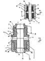
- the sealing unit has a bush-shaped basic body 1, which serves as a guide for a rod 2 of a piston ( Fig. 3 ).
- the rod 2 abuts against the inner wall 3 of the main body 1, so that the rod 2 is guided reliably in its axial displacement.
- sealing element 4 On the in Fig. 2 left end of the base body 1 is a sealing element 4 and on the right end a sealing element 5.
- the sealing element 4 is provided for sealing a hydraulic medium and the sealing element 5 for sealing against a pneumatic medium.
- Both sealing elements 4, 5 each have a peripheral sealing edge 6, 7, with which they rest sealingly on the rod 2.
- the two sealing edges 6, 7 are in the area outside of the main body.
- the main body 1 is advantageously made of a thermoset, such as reinforced epoxy resin compound, phenolic resin compound, or alternatively of reinforced thermoplastic, such as polyamide (PA), polyphenylene sulfide (PPS) - or polyetheretherketone (PEEK) compound, and has an annular flange 8, which is advantageously formed by a radially projecting circumferential collar.
- the two sealing elements 4, 5 extend to the mutually remote outer sides 9, 10 of the flange 8, which is advantageously formed integrally with the base body 1.
- the flange 8 is penetrated by at least one radial opening 11.
- two radially aligned radial openings 11 are provided which are advantageously located in half the width of the flange 8.
- the radial openings 11 open radially outward into a circumferential recess 12 whose bottom is concavely curved in axial section.
- the radial openings 11 form an inner and the circumferential recess 12 an outer Drainageabtechnisch.
- the drainage occurring between the rod 2 and the inner wall 3 of the sealing unit can pass through the radial openings 11 radially outwardly into the recess 12. Due to the circumferential recess 12, care must not be taken to a positionally accurate installation position of the sealing unit. This ensures a simple and safe installation.
- Fig. 3 shows by way of example a housing 13, in which the sealing unit is installed.
- the housing 13 has an axial passage opening 14 which receives the seal unit.
- the passage opening 14 has three different sections 15 to 17 in diameter.
- the section 15 has the largest diameter and receives the hydraulic sealing element 4.
- the smaller diameter portion 16 receives the pneumatic sealing element 5.
- the smallest in diameter portion 17 of the through hole 14 has only a very small axial length.
- the pneumatic sealing element 5 protrudes in a manner to be described.
- the housing 13 has a greater length than the sealing unit, which can be protected thereby housed in the housing 13.
- the wall of the housing 13 is penetrated by at least one radial bore 18, which opens into the recess 12 of the flange 8. Thereby, the drainage located in the recess 12 can be discharged through the radial bore 18 to the outside.
- the hydraulic sealing element 4 has a resting on the outer wall 20 of the base body 1 static sealing portion 21, which extends to the outside 9 of the flange 8 and is provided on its radially outer surface with a profiling 22, which is preferably a wave profiling. When not installed, the profiling 22 projects radially beyond the flange 8. As a result, the profiling 22 is elastically deformed in the installation position of the sealing unit such that a perfect static seal is achieved for the wall of the section 15 of the through-opening 14.
- the outer diameter of the flange 8 corresponds to the diameter of the section 15th
- the sealing portion 21 merges into a dynamic sealing portion 23, which surrounds the end face of the main body 1 and thus covers it.
- a recess 24 is provided on the end face of the base body 1, which is open to the inside.
- the sealing portion 23 engages with its one end.
- the sealing portion 23 protrudes to the bottom of the recess 24.
- the sealing edge 6 of the annular dynamic sealing portion 23 is in the non-installed state radially inwardly beyond the inner wall 3 of the body 1 before. As a result, when the rod 2 is mounted, the sealing portion 23 seals against the outside of the rod 2 under radial prestressing.
- the pneumatic sealing element 15 also has an annular static sealing portion 25 which rests on the base body and extends to the outside 10 of the flange 8.
- the outside of the sealing portion 25 is provided with a profiling 26, which is advantageously wave-shaped. In the installation position, the profiling 26 is elastically deformed, whereby a perfect seal to the inner wall of the portion 16 of the through hole 14 is achieved. This results in an optimal static seal.
- the sealing element 5 has a dynamic sealing portion 27, which is annular and surrounds the corresponding end face of the base body 1. At this end face, a recess 28 is likewise provided, which is open radially inwardly and into which a part of the dynamic sealing section 27 engages.
- the dynamic sealing portion 27 extends to the bottom of the front-side recess 28th
- the annular sealing edge 7 of the dynamic sealing portion 27 protrudes radially inwardly over the inner wall 3 of the through hole 14 when the rod 2 is not mounted. When mounted rod 2, the sealing edge 7 is under radial bias sealingly against the rod 2.
- the outer side 10 of the flange 8 protrudes radially beyond the static sealing portion 25.
- this protruding part of the outer side 10 can act as a stop when the sealing unit is installed in the housing 13.
- the sealing unit is pressed into the through hole 14 of the housing 13, wherein the profilings 22, 26 of the two sealing elements 4, 5 are elastically deformed in the manner described.
- the sealable rod 2 is pushed into the seal unit, the dynamic seal portions 23, 27 of the seal members 4, 5 are elastically deformed, thereby the sealing edges 6, 7 bear sealingly under radial prestress on the rod 2.
- the two sealing elements 4, 5 consist of the materials suitable therefor, for example nitrile rubber (NBR), acrylic rubber (ACM) or fluororubber (FPM).
- NBR nitrile rubber
- ACM acrylic rubber
- FPM fluororubber
- the sealing elements 4, 5 are advantageously firmly connected to the main body 1, wherein the type of attachment of the material of the base body 1 and the sealing elements 4, 5 depends.
- the described sealing unit is characterized in that it is compact and can be easily mounted.
- the sealing unit is a composite body and, in the manner described, is designed to have integrated a rod guide as well as a drainage outlet. Since the guide body 1 has the annular recess 12, the radial opening 11 of the base body 1 need not be brought into coincidence with the radial bore 18 of the housing 13, which simplifies the assembly.
- the sealing unit is particularly suitable for systems in which pistons or rods are guided in the smallest space and at the same time have to be sealed against different media.
- the main body 1 can be provided on the inside with a (not shown) Gleitbuchse.
- the dynamic sealing portions 23, 27 are formed as sealing lips which extend axially beyond the base body 1 and have a favorable for a good dynamic sealing flexibility. The flexibility is not impaired in the installation position, because the sections 15 and 17 of the passage opening 14 of the housing 13 have a large diameter which is greater than the outer diameter of the dynamic sealing portions 23, 27th
Landscapes
- Engineering & Computer Science (AREA)
- General Engineering & Computer Science (AREA)
- Mechanical Engineering (AREA)
- Physics & Mathematics (AREA)
- Fluid Mechanics (AREA)
- Sealing Devices (AREA)
Description
- Die Erfindung betrifft eine Dichtungseinrichtung für Stangen nach dem Oberbegriff des Anspruches
- Es sind Dichtungseinrichtungen für Stangen bekannt wie in
DE 196 80 491 B4 die ein Dichtelement in Form einer Hydraulikdichtung, ein Dichtelement in Form einer Pneumatikdichtung sowie einen Führungskörper aufweisen, mit dem die abzudichtende Stange geführt wird. Diese drei Baueinheiten werden einzeln montiert, was sehr zeitaufwändig ist. Aufgrund der Summe der Teiletoleranzen zuzüglich der Montage- und Lagetoleranzen ergibt sich für die Dichtungseinrichtung eine sehr hohe Systemtoleranz, die beim Einsatz der Dichtungseinrichtung zu Problemen führen kann. - Der Erfindung liegt die Aufgabe zugrunde, die gattungsgemäße Dichtungseinrichtung so auszubilden, dass sie bei nur geringer Toleranz einfach und zeitsparend montiert werden kann.
- Diese Aufgabe wird bei der gattungsgemäßen Dichtungseinrichtung erfindungsgemäß mit den kennzeichnenden Merkmalen des Anspruches 1 gelöst.
- Bei der erfindungsgemäßen Dichtungseinrichtung bilden die Dichtelemente und der Führungskörper einen Verbundkörper in Form einer Dichtungseinheit. Sie lässt sich in einem Arbeitsgang als Einheit montieren. Dadurch ist eine sehr einfache und zeitsparende Montage gewährleistet. Die Dichtungseinheit führt auch zu einer relativ geringen Systemtoleranz, weil nur die Montage- und Lagetoleranz der Dichtungseinheit zu berücksichtigen ist. Vorteilhaft sind die beiden Dichtelemente auf jeweils einem Ende des Führungskörpers angeordnet. Die beiden Dichtelemente liegen dadurch räumlich ausreichend weit voneinander getrennt, so dass sie sich nicht gegenseitig beeinflussen.
- Um im Einsatz der Dichtungseinrichtung auftretende Drainage zuverlässig abführen zu können, ist vorteilhaft zwischen den Dichtelementen im Führungskörper eine Drainageableitung vorgesehen. Über sie kann die eventuell auftretende Drainage nach außen abgeleitet werden.
- Die Ausbildung nach Anspruch 4 ergibt eine Dichtungseinrichtung, bei der die Drainageableitung die Vertiefung aufweist, die sich wenigstens über einen Teil des Umfanges des Führungskörpers erstreckt und in die wenigstens eine den Führungskörper durchsetzende Öffnung mündet. Über diese Öffnung wird die eventuell auftretende Drainage nach außen zur Vertiefung abgeleitet, über die die Drainage abgeleitet bzw. abgeführt werden kann. Da die Öffnung in die Vertiefung mündet, muss beim Einbau der Dichtungseinrichtung in ein entsprechendes Gehäuse oder einen Aufnahmeraum eines Gerätes die Öffnung nicht in aufwändiger Weise in Flucht bzw. in Deckung zu einer Abführöffnung im Gehäuse bzw. im Aufnahmeraum gebracht werden. Wesentlich ist nur, dass die Vertiefung am Führungskörper mit der Ableitungsöffnung des Gehäuses bzw. des Aufnahmeraumes in Verbindung steht.
- Besonders vorteilhaft ist es, wenn sich diese Vertiefung über den gesamten Umfang des Führungskörpers erstreckt. Dann muss beim Einbau der Dichtungseinrichtung in den Aufnahmeraum oder in das Gehäuse nicht auf eine radiale Ausrichtung der Öffnung im Führungskörper geachtet werden. Die umlaufende Vertiefung stellt in diesem Falle jederzeit sicher, dass die Drainage über die Öffnung des Führungskörpers in die Ableitungsöffnung des Aufnahmeraumes bzw. des Gehäuses gelangt. Beim Einbau muss lediglich dafür gesorgt werden, dass die umlaufende Vertiefung axial gegenüber der Ableitungsöffnung des Gehäuses bzw. Aufnahmeraumes ausgerichtet ist. Dies lässt sich sehr einfach beispielsweise durch einen Anschlag erreichen, an dem die Dichtungseinrichtung beim Einbau zur Anlage kommt und wodurch diese Lagepositionierung der Vertiefung des Führungskörpers zur Ableitungsöffnung gewährleistet wird.
- Die Vertiefung ist bei einer vorteilhaften Ausführungsform an einem nach außen ragenden umlaufenden Flansch des Führungskörpers vorgesehen. Dieser Flansch kann beispielsweise als Anschlag genutzt werden, um beim Einbau der Dichtungseinrichtung die Ausrichtung der Vertiefung relativ zur Ableitungsöffnung in einfacher Weise zu erreichen.
- Vorteilhaft durchsetzt die Öffnung des Führungskörpers den Flansch.
- Der umlaufende Flansch des Führungskörpers trennt vorteilhaft die beiden Dichtelemente voneinander, so dass durch den Flansch eine räumliche Trennung der beiden Dichtelemente gewährleistet ist.
- Die beiden Dichtelemente ragen vorteilhaft mit einem dynamischen Dichtabschnitt axial über den Führungskörper. Dadurch wird erreicht, dass die dynamischen Dichtabschnitte die für die dynamische Dichtung erforderliche Bewegungsfreiheit haben.
- Eine zuverlässige Abdichtung wird erreicht, wenn die dynamischen Dichtabschnitte im axial überstehenden Bereich mit einer Dichtkante versehen sind, die dichtend an der Stange anliegt.
- Vorteilhaft sind die dynamischen Dichtabschnitte als Dichtlippen ausgebildet. Sie liegen dann unter radialer Vorspannung an der abzudichtenden Stange an, wodurch sich eine einwandfreie Abdichtung erreichen lässt.
- Bei einer vorteilhaften Ausführungsform umgreifen die Dichtelemente den Führungskörper stirnseitig. Dadurch wird der Führungskörper beispielsweise vor schädlichen Medien geschützt, die den Führungskörper angreifen könnten.
- Damit die Dichtelemente in diesem Falle zuverlässig am Führungskörper gehalten werden können, ist er an seinen Stirnseiten jeweils mit einer Vertiefung versehen, in die der dynamische Dichtabschnitt eingreift.
- Die Dichtelemente sind außerdem vorteilhaft mit einem statischen Dichtabschnitt versehen, mit dem die Dichtelemente den Führungskörper umgeben. Die statischen Dichtabschnitte der Dichtelemente liegen dann an der Wandung des Aufnahmeraumes oder des Gehäuses an und stellen sicher, dass in diesem Bereich kein abzudichtendes Medium hindurchtreten kann.
- Die statische Abdichtung lässt sich in vorteilhafter Weise erhöhen, wenn der statische Dichtabschnitt an seiner Außenseite mit einer elastisch verformbaren Profilierung versehen ist. Sie wird beim Einbau der Dichtungseinrichtung elastisch verformt, wodurch eine zuverlässige statische Abdichtung erreicht wird.
- Der Anmeldungsgegenstand ergibt sich nicht nur aus dem Gegenstand der einzelnen Patentansprüche, sondern auch durch alle in den Zeichnungen und der Beschreibung offenbarten Angaben und Merkmale. Sie werden, auch wenn sie nicht Gegenstand der Ansprüche sind, als erfindungswesentlich beansprucht, soweit sie einzeln oder in Kombination gegenüber dem Stand der Technik neu sind.
- Weitere Merkmale der Erfindung ergeben sich aus den weiteren Ansprüchen, der Beschreibung und der Zeichnung.
- Die Erfindung wird anhand eines in der Zeichnung dargestellten Ausführungsbeispieles näher erläutert. Es zeigen
- Fig. 1
- in perspektivischer Darstellung eine erfindungsgemäße Dichtungseinrichtung,
- Fig. 2
- einen Axialschnitt durch die erfindungsgemäße Dichtungseinrichtung,
- Fig. 3
- die in ein Gehäuse eingebaute Dichtungseinrichtung gemäß
Fig. 2 , - Fig. 4
- einen weiteren Axialschnitt durch die Dichtungseinrichtung gemäß
Fig. 1 . - Mit der Dichtungseinrichtung, die nachfolgend als Dichtungseinheit bezeichnet wird, ist es möglich, gegen unterschiedliche Medien dynamisch abzudichten, eventuell auftretendes Drainagemedium abzuführen und dabei gleichzeitig eine Gleitführungsfunktion zu gewährleisten.
- Die Dichtungseinheit hat einen buchsenförmigen Grundkörper 1, der als Führung für eine Stange 2 eines Kolbens dient (
Fig. 3 ). Die Stange 2 liegt an der Innenwand 3 des Grundkörpers 1 an, so dass die Stange 2 bei ihrer Axialverschiebung zuverlässig geführt wird. - Auf dem in
Fig. 2 linken Ende des Grundkörpers 1 befindet sich ein Dichtelement 4 und auf dem rechten Ende ein Dichtelement 5. Das Dichtelement 4 ist zur Abdichtung eines Hydraulikmediums und das Dichtelement 5 zur Abdichtung gegen ein Pneumatikmedium vorgesehen. Beide Dichtelemente 4, 5 haben jeweils eine umlaufende Dichtkante 6, 7, mit der sie dichtend auf der Stange 2 aufliegen. Die beiden Dichtkanten 6, 7 liegen im Bereich außerhalb des Grundkörpers 1. - Der Grundkörper 1 besteht vorteilhaft aus einem Duroplast, wie verstärkter Epoxidharz-Compound, Phenolharz-Compound, oder alternativ aus verstärktem Thermoplast, wie Polyamid (PA), Polyphenylensulfid (PPS)- oder Polyetheretherketon (PEEK)-Compound, und hat einen Ringflansch 8, der vorteilhaft durch einen radial vorstehenden umlaufenden Bund gebildet wird. Die beiden Dichtelemente 4, 5 erstrecken sich bis zu den voneinander abgewandten Außenseiten 9, 10 des Flansches 8, der vorteilhaft einstückig mit dem Grundkörper 1 ausgebildet ist.
- Der Flansch 8 wird von wenigstens einer Radialöffnung 11 durchsetzt. Im dargestellten Ausführungsbeispiel sind zwei fluchtend zueinander liegende Radialöffnungen 11 vorgesehen, die sich vorteilhaft in halber Breite des Flansches 8 befinden. Die Radialöffnungen 11 münden radial außen in eine umlaufende Vertiefung 12, deren Boden im Axialschnitt konkav gekrümmt ist. Die Radialöffnungen 11 bilden eine innere und die umlaufende Vertiefung 12 eine äußere Drainageableitung. Die zwischen der Stange 2 und der Innenwand 3 der Dichtungseinheit auftretende Drainage kann durch die Radialöffnungen 11 radial nach außen in die Vertiefung 12 gelangen. Aufgrund der umlaufenden Vertiefung 12 muss auf eine lagegenaue Einbauposition der Dichtungseinheit nicht geachtet werden. Dadurch ist eine einfache und sichere Montage gewährleistet.
-
Fig. 3 zeigt beispielhaft ein Gehäuse 13, in das die Dichtungseinheit eingebaut wird. Das Gehäuse 13 hat eine axiale Durchgangsöffnung 14, welche die Dichtungseinheit aufnimmt. Die Durchgangsöffnung 14 weist drei im Durchmesser unterschiedliche Abschnitte 15 bis 17 auf. Der Abschnitt 15 hat den größten Durchmesser und nimmt das Hydraulikdichtelement 4 auf. Der im Durchmesser kleinere Abschnitt 16 nimmt das Pneumatikdichtelement 5 auf. Der im Durchmesser kleinste Abschnitt 17 der Durchgangsöffnung 14 hat nur sehr geringe axiale Länge. In diesen Abschnitt 17 ragt das Pneumatikdichtelement 5 in noch zu beschreibender Weise. Das Gehäuse 13 hat eine größere Länge als die Dichtungseinheit, die dadurch geschützt im Gehäuse 13 untergebracht werden kann. - Die Wandung des Gehäuses 13 wird durch wenigstens eine Radialbohrung 18 durchsetzt, die in die Vertiefung 12 des Flansches 8 mündet. Dadurch kann die in der Vertiefung 12 befindliche Drainage durch die Radialbohrung 18 nach außen abgeführt werden.
- Am Übergang vom Abschnitt 15 in den Abschnitt 16 befindet sich eine radiale Ringschulter 19, an der der Flansch 8 mit seiner Außenseite 10 in der Einbaulage anliegt. Dadurch lässt sich die Einbauposition der Dichtungseinheit im Gehäuse 13 einfach finden.
- Das Hydraulikdichtelement 4 hat einen auf der Außenwand 20 des Grundkörpers 1 aufliegenden statischen Dichtabschnitt 21, der sich bis zur Außenseite 9 des Flansches 8 erstreckt und an seiner radial äußeren Mantelfläche mit einer Profilierung 22 versehen ist, die vorzugsweise eine Wellenprofilierung ist. Im nicht eingebauten Zustand steht die Profilierung 22 radial über den Flansch 8 vor. Dadurch wird die Profilierung 22 in der Einbaulage der Dichtungseinheit elastisch so verformt, dass eine einwandfreie statische Abdichtung zur Wandung des Abschnittes 15 der Durchgangsöffnung 14 erreicht wird. Der Außendurchmesser des Flansches 8 entspricht dem Durchmesser des Abschnittes 15.
- Der Dichtabschnitt 21 geht in einen dynamischen Dichtabschnitt 23 über, der die Stirnseite des Grundkörpers 1 umgreift und sie somit abdeckt. Um einen sicheren Halt dieses Dichtabschnittes 23 am Grundkörper 1 zu gewährleisten, ist an der Stirnseite des Grundkörpers 1 eine Vertiefung 24 vorgesehen, die nach innen offen ist. In diese Vertiefung 24 greift der Dichtabschnitt 23 mit seinem einen Ende ein. Der Dichtabschnitt 23 ragt bis zum Boden der Vertiefung 24. Die Dichtkante 6 des ringförmigen dynamischen Dichtabschnittes 23 steht in nicht eingebautem Zustand radial nach innen über die Innenwand 3 des Grundkörpers 1 vor. Dadurch liegt der Dichtabschnitt 23 bei montierter Stange 2 unter radialer Vorspannung dichtend an der Außenseite der Stange 2 an.
- Das Pneumatikdichtelement 15 hat ebenfalls einen ringförmigen statischen Dichtabschnitt 25, der auf dem Grundkörper aufsitzt und bis zur Außenseite 10 des Flansches 8 reicht. Die Außenseite des Dichtabschnittes 25 ist mit einer Profilierung 26 versehen, die vorteilhaft wellenförmig ausgebildet ist. In der Einbaulage wird die Profilierung 26 elastisch verformt, wodurch eine einwandfreie Abdichtung zur Innenwand des Abschnittes 16 der Durchgangsöffnung 14 erreicht wird. Dadurch ergibt sich eine optimale statische Abdichtung.
- Das Dichtelement 5 hat einen dynamischen Dichtabschnitt 27, der ringförmig ausgebildet ist und die entsprechende Stirnseite des Grundkörpers 1 umgreift. An dieser Stirnseite ist ebenfalls eine Vertiefung 28 vorgesehen, die radial nach innen offen ist und in die ein Teil des dynamischen Dichtabschnittes 27 eingreift. Der dynamische Dichtabschnitt 27 erstreckt sich bis zum Boden der stirnseitigen Vertiefung 28.
- Die ringförmige Dichtkante 7 des dynamischen Dichtabschnittes 27 steht bei nicht montierter Stange 2 radial nach innen über die Innenwand 3 der Durchgangsöffnung 14 vor. Bei montierter Stange 2 liegt die Dichtkante 7 unter radialer Vorspannung dichtend an der Stange 2 an.
- Im dargestellten Ausführungsbeispiel ragt die Außenseite 10 des Flansches 8 radial über den statischen Dichtabschnitt 25 vor. Dadurch kann dieser überstehende Teil der Außenseite 10 als Anschlag wirken, wenn die Dichtungseinheit in das Gehäuse 13 eingebaut wird. Hierbei wird die Dichtungseinheit in die Durchgangsöffnung 14 des Gehäuses 13 eingepresst, wobei die Profilierungen 22, 26 der beiden Dichtelemente 4, 5 in der beschriebenen Weise elastisch verformt werden. Die Dichtungseinheit sitzt mit Presssitz in der Durchgangsöffnung 14 des Gehäuses 13. Wird die abzudichtende Stange 2 in die Dichtungseinheit geschoben, werden die dynamischen Dichtabschnitte 23, 27 der Dichtelemente 4, 5 elastisch verformt, wodurch die Dichtkanten 6, 7 unter radialer Vorspannung an der Stange 2 dichtend anliegen.
- Die beiden Dichtelemente 4, 5 bestehen hinsichtlich des abzudichtenden Mediums aus den dafür geeigneten Werkstoffen, beispielsweise Nitrilkautschuk (NBR), Acrylkautschuk (ACM) oder Fluorkautschuk (FPM).
- Die Dichtelemente 4, 5 werden mit dem Grundkörper 1 vorteilhaft fest miteinander verbunden, wobei die Art der Befestigung vom Werkstoff des Grundkörpers 1 sowie der Dichtelemente 4, 5 abhängt.
- Die beschriebene Dichtungseinheit zeichnet sich dadurch aus, dass sie kompakt ausgebildet ist und einfach montiert werden kann. Die Dichtungseinheit ist ein Verbundkörper und in der beschriebenen Weise so ausgebildet, dass sie eine Stangenführung sowie eine Drainageableitung integriert hat. Da der Führungskörper 1 die Ringvertiefung 12 aufweist, muss die Radialöffnung 11 des Grundkörpers 1 nicht mit der Radialbohrung 18 des Gehäuses 13 in Deckung gebracht werden, was die Montage besonders vereinfacht. Die Dichtungseinheit eignet sich besonders für Systeme, bei denen Kolben oder Stangen auf kleinstem Raum geführt und gleichzeitig gegen unterschiedliche Medien abgedichtet werden müssen.
- Der Grundkörper 1 kann innenseitig mit einer (nicht dargestellten) Gleitbuchse versehen sein. Die dynamischen Dichtabschnitte 23, 27 sind als Dichtlippen ausgebildet, die sich axial über den Grundkörper 1 hinaus erstrecken und eine für eine gute dynamische Abdichtung vorteilhafte Flexibilität haben. Die Flexibilität ist in der Einbaulage nicht beeinträchtigt, weil die Abschnitte 15 und 17 der Durchgangsöffnung 14 des Gehäuses 13 einen großen Durchmesser haben, der größer ist als der Außendurchmesser der dynamischen Dichtabschnitte 23, 27.
Claims (7)
- Dichtungseinrichtung für Stangen (2), mit zwei Dichtelementen (4, 5), die gegen unterschiedliche Medien abdichten, mit einem Führungskörper (1) für die Stange (2), der zusammen mit den Dichtelementen (4, 5) einen Verbundkörper in Form einer Dichtungseinheit bildet, die als Einheit montierbar ist, wobei der Führungskörper (1) mit einer Drainageableitung (11, 12) versehen ist, die wenigstens eine den Führungskörper (1) durchsetzende Öffnung (11) aufweist, die in eine an der Außenseite des Führungskörpers (1) vorgesehene, wenigstens über einen Teil seines Umfanges verlaufende Vertiefung (12) mündet, wobei die Dichtelemente (4, 5) einen statischen Dichtabschnitt (21, 25) und einen dynamischen Dichtabschnitt (23, 27) aufweisen,
dadurch gekennzeichnet, dass der Führungskörper (1) einen Ringflansch (8) aufweist, der durch einen radial vorstehenden umlaufenden Bund gebildet ist, dass die Dichtelemente (4, 5) mit dem statischen Dichtabschnitt (21, 25) den Führungskörper (1) umgeben, dass die beiden Dichtelemente (4, 5) sich bis zu den voneinander abgewandten Außenseiten (9, 10) des Ringflansches (8) erstrecken, dass im Ringflansch (8) die Vertiefung (12) und die Öffnung (11) vorgesehen ist, die den Ringflansch (8) radial durchsetzt, dass der statische Dichtabschnitt (21) des einen Dichtelementes (4) sich bis zur einen Außenseite (9) des Ringflansches (8) erstreckt und an seiner radial äußeren Mantelfläche mit einer elastisch verformbaren Profilierung (22) versehen ist, die im nicht eingebauten Zustand über den Ringflansch (8) radial vorsteht, dass der statische Dichtabschnitt (25) des anderen Dichtelementes (5) bis zur anderen Außenseite (10) des Ringflansches (8) sich erstreckt und an seiner Außenseite mit einer elastisch verformbaren Profilierung (26) versehen ist, und dass der Radialflansch (8) mit seiner Außenseite (10) radial über den statischen Dichtabschnitt (25) des anderen Dichtelementes (5) ragt. - Dichtungseinrichtung nach Anspruch 1,
dadurch gekennzeichnet, dass sich die Vertiefung (12) über den Umfang des Führungskörpers (1) erstreckt. - Dichtungseinrichtung nach Anspruch 1 oder 2,
dadurch gekennzeichnet, dass die Dichtelemente (4, 5) mit dem dynamischen Dichtabschnitt (23, 27) axial über den Führungskörper (1) ragen. - Dichtungseinrichtung nach einem der Ansprüche 1 bis 3,
dadurch gekennzeichnet, dass die dynamischen Dichtabschnitte (23, 27) der Dichtelemente (4, 5) im axial überstehenden Bereich eine Dichtkante (6, 7) aufweisen. - Dichtungseinrichtung nach einem der Ansprüche 1 bis 4,
dadurch gekennzeichnet, dass die dynamischen Dichtabschnitte (23, 27) als Dichtlippen ausgebildet sind. - Dichtungseinrichtung nach einem der Ansprüche 1 bis 5,
dadurch gekennzeichnet, dass die Dichtelemente (4, 5) den Führungskörper (1) stirnseitig umgreifen. - Dichtungseinrichtung nach einem der Ansprüche 1 bis 6,
dadurch gekennzeichnet, dass der Führungskörper (1) an seinen Stirnseiten jeweils mit einer Vertiefung (24, 28) versehen ist, in die der dynamische Dichtabschnitt (23, 27) eingreift.
Applications Claiming Priority (1)
| Application Number | Priority Date | Filing Date | Title |
|---|---|---|---|
| DE201210021077 DE102012021077A1 (de) | 2012-10-19 | 2012-10-19 | Dichtungseinrichtung für Stangen |
Publications (2)
| Publication Number | Publication Date |
|---|---|
| EP2722567A1 EP2722567A1 (de) | 2014-04-23 |
| EP2722567B1 true EP2722567B1 (de) | 2015-12-30 |
Family
ID=49447323
Family Applications (1)
| Application Number | Title | Priority Date | Filing Date |
|---|---|---|---|
| EP13004946.3A Active EP2722567B1 (de) | 2012-10-19 | 2013-10-16 | Dichtungseinrichtung für Stangen |
Country Status (3)
| Country | Link |
|---|---|
| EP (1) | EP2722567B1 (de) |
| DE (1) | DE102012021077A1 (de) |
| ES (1) | ES2565534T3 (de) |
Cited By (1)
| Publication number | Priority date | Publication date | Assignee | Title |
|---|---|---|---|---|
| EP3759333B1 (de) * | 2018-02-28 | 2022-05-11 | Vialle Group B.V. | Kraftstoffzufuhrsystem und anordnung zum einspritzen von verflüssigtem dampf unter hohem druck in eine brennkammer |
Families Citing this family (2)
| Publication number | Priority date | Publication date | Assignee | Title |
|---|---|---|---|---|
| DE102017102028A1 (de) | 2017-02-02 | 2018-08-02 | Nidec Gpm Gmbh | Vorrichtung zur Führung eines Kraftübertragungselements |
| DE102019122718A1 (de) * | 2019-08-23 | 2021-02-25 | Nidec Gpm Gmbh | Kolbenstangenabdichtung |
Family Cites Families (6)
| Publication number | Priority date | Publication date | Assignee | Title |
|---|---|---|---|---|
| US3490774A (en) * | 1966-03-29 | 1970-01-20 | Dresser Ind | Packing for a reciprocal plunger rod |
| IT969356B (it) * | 1971-10-01 | 1974-03-30 | Kaller S | Dispositivo di chiusura a tenuta |
| HU174165B (hu) * | 1974-06-26 | 1979-11-28 | Walter Hunger | Napravljajuhhij i uplotnjajuhhij mekhanizm k porshnjam, shatunam i podobnym detaljam |
| DE19523217A1 (de) * | 1995-06-27 | 1997-01-02 | Schaeffler Waelzlager Kg | Abdichtungen in einem Geberzylinder |
| US7806411B2 (en) * | 2006-11-27 | 2010-10-05 | A.W. Chesterton Company | Radial seal assembly |
| DE102008011132A1 (de) * | 2008-02-26 | 2009-08-27 | Zf Friedrichshafen Ag | Druckmittelzylinder für ein hydraulisches Betätigungssystem eines Kraftfahrzeuges |
-
2012
- 2012-10-19 DE DE201210021077 patent/DE102012021077A1/de not_active Withdrawn
-
2013
- 2013-10-16 ES ES13004946.3T patent/ES2565534T3/es active Active
- 2013-10-16 EP EP13004946.3A patent/EP2722567B1/de active Active
Cited By (1)
| Publication number | Priority date | Publication date | Assignee | Title |
|---|---|---|---|---|
| EP3759333B1 (de) * | 2018-02-28 | 2022-05-11 | Vialle Group B.V. | Kraftstoffzufuhrsystem und anordnung zum einspritzen von verflüssigtem dampf unter hohem druck in eine brennkammer |
Also Published As
| Publication number | Publication date |
|---|---|
| DE102012021077A1 (de) | 2014-04-24 |
| EP2722567A1 (de) | 2014-04-23 |
| ES2565534T3 (es) | 2016-04-05 |
Similar Documents
| Publication | Publication Date | Title |
|---|---|---|
| EP0525288B1 (de) | Kassettendichtung | |
| EP2362119B1 (de) | Radialwellendichtung zur Trennung zweier Medien | |
| EP2941798A1 (de) | Umweltdichtes steckverbindergehäuse | |
| DE102016219592A1 (de) | Nehmerzylinder für ein hydraulisches Ausrücksystem zur Betätigung einer Reibungskupplung | |
| EP2692559B1 (de) | Luftfiltereinrichtung mit Filterelement | |
| EP2618032B1 (de) | Wellendichtung, insbesondere Radialwellendichtung | |
| EP2722567A1 (de) | Dichtungseinrichtung für Stangen | |
| EP2852015B1 (de) | Kabeldurchführungseinrichtung | |
| DE3016231C2 (de) | Dichtungsanordnung | |
| WO2014131510A1 (de) | Flachdichtung für flanschverbindungen | |
| DE102008012488A1 (de) | Teilelement für ein Dichtelement eines Lagers | |
| EP2431627B1 (de) | Scheibenbremse mit einer Dichtungseinrichtung | |
| DE102011087103A1 (de) | Geberzylinder | |
| DE102010053945A1 (de) | Dichtungseinrichtung | |
| DE102009042822B4 (de) | Nehmerzylinder | |
| DE2921669A1 (de) | Dichtung | |
| EP2801725B1 (de) | Vorrichtung mit mindestens einem Kanal zum Führen eines gasförmigen oder flüssigen Betriebsmittels | |
| DE4340051A1 (de) | Flanschverbindung | |
| EP2487395B1 (de) | Rücklaufventil | |
| DE4223251A1 (de) | Automatisch montierbare Steckkupplung für Leitungsschläuche in Kraftfahrzeugen | |
| DE102008035315A1 (de) | Dichteinrichtung | |
| DE102012206626B4 (de) | Trägerrahmendichtung mit verringertem Platzbedarf | |
| DE102017119264A1 (de) | Nockenwellenversteller mit Dichtung zwischen Außendeckel und Stator | |
| DE102014019116A1 (de) | Druckluftmitteleinrichtung mit aufgrund von Formdichtungen variablen Strömungsverbindungen | |
| DE102022110971A1 (de) | Fluidleitungsbauteil mit Axialdichtung |
Legal Events
| Date | Code | Title | Description |
|---|---|---|---|
| PUAI | Public reference made under article 153(3) epc to a published international application that has entered the european phase |
Free format text: ORIGINAL CODE: 0009012 |
|
| AK | Designated contracting states |
Kind code of ref document: A1 Designated state(s): AL AT BE BG CH CY CZ DE DK EE ES FI FR GB GR HR HU IE IS IT LI LT LU LV MC MK MT NL NO PL PT RO RS SE SI SK SM TR |
|
| AX | Request for extension of the european patent |
Extension state: BA ME |
|
| 17P | Request for examination filed |
Effective date: 20141023 |
|
| RBV | Designated contracting states (corrected) |
Designated state(s): AL AT BE BG CH CY CZ DE DK EE ES FI FR GB GR HR HU IE IS IT LI LT LU LV MC MK MT NL NO PL PT RO RS SE SI SK SM TR |
|
| REG | Reference to a national code |
Ref country code: DE Ref legal event code: R079 Ref document number: 502013001671 Country of ref document: DE Free format text: PREVIOUS MAIN CLASS: F16J0015320000 Ipc: F16J0015000000 |
|
| GRAP | Despatch of communication of intention to grant a patent |
Free format text: ORIGINAL CODE: EPIDOSNIGR1 |
|
| RIC1 | Information provided on ipc code assigned before grant |
Ipc: F16J 15/32 20060101ALI20150416BHEP Ipc: F16J 15/56 20060101ALI20150416BHEP Ipc: F15B 15/14 20060101ALI20150416BHEP Ipc: F16J 15/00 20060101AFI20150416BHEP |
|
| INTG | Intention to grant announced |
Effective date: 20150430 |
|
| GRAS | Grant fee paid |
Free format text: ORIGINAL CODE: EPIDOSNIGR3 |
|
| RAP1 | Party data changed (applicant data changed or rights of an application transferred) |
Owner name: NIDEC GPM GMBH |
|
| GRAA | (expected) grant |
Free format text: ORIGINAL CODE: 0009210 |
|
| AK | Designated contracting states |
Kind code of ref document: B1 Designated state(s): AL AT BE BG CH CY CZ DE DK EE ES FI FR GB GR HR HU IE IS IT LI LT LU LV MC MK MT NL NO PL PT RO RS SE SI SK SM TR |
|
| REG | Reference to a national code |
Ref country code: GB Ref legal event code: FG4D Free format text: NOT ENGLISH |
|
| REG | Reference to a national code |
Ref country code: CH Ref legal event code: EP |
|
| REG | Reference to a national code |
Ref country code: AT Ref legal event code: REF Ref document number: 767648 Country of ref document: AT Kind code of ref document: T Effective date: 20160115 |
|
| REG | Reference to a national code |
Ref country code: IE Ref legal event code: FG4D Free format text: LANGUAGE OF EP DOCUMENT: GERMAN |
|
| REG | Reference to a national code |
Ref country code: DE Ref legal event code: R096 Ref document number: 502013001671 Country of ref document: DE |
|
| REG | Reference to a national code |
Ref country code: ES Ref legal event code: FG2A Ref document number: 2565534 Country of ref document: ES Kind code of ref document: T3 Effective date: 20160405 |
|
| REG | Reference to a national code |
Ref country code: LT Ref legal event code: MG4D |
|
| REG | Reference to a national code |
Ref country code: SE Ref legal event code: TRGR |
|
| PG25 | Lapsed in a contracting state [announced via postgrant information from national office to epo] |
Ref country code: HR Free format text: LAPSE BECAUSE OF FAILURE TO SUBMIT A TRANSLATION OF THE DESCRIPTION OR TO PAY THE FEE WITHIN THE PRESCRIBED TIME-LIMIT Effective date: 20151230 Ref country code: NO Free format text: LAPSE BECAUSE OF FAILURE TO SUBMIT A TRANSLATION OF THE DESCRIPTION OR TO PAY THE FEE WITHIN THE PRESCRIBED TIME-LIMIT Effective date: 20160330 Ref country code: LT Free format text: LAPSE BECAUSE OF FAILURE TO SUBMIT A TRANSLATION OF THE DESCRIPTION OR TO PAY THE FEE WITHIN THE PRESCRIBED TIME-LIMIT Effective date: 20151230 |
|
| REG | Reference to a national code |
Ref country code: NL Ref legal event code: MP Effective date: 20151230 |
|
| REG | Reference to a national code |
Ref country code: DE Ref legal event code: R082 Ref document number: 502013001671 Country of ref document: DE Representative=s name: JACKISCH-KOHL UND KOHL, DE Ref country code: DE Ref legal event code: R081 Ref document number: 502013001671 Country of ref document: DE Owner name: NIDEC GPM GMBH, DE Free format text: FORMER OWNER: NIDEC GPM GMBH, 98673 AUENGRUND, DE Ref country code: DE Ref legal event code: R081 Ref document number: 502013001671 Country of ref document: DE Owner name: KACO GMBH + CO. KG, DE Free format text: FORMER OWNER: NIDEC GPM GMBH, 98673 AUENGRUND, DE |
|
| PG25 | Lapsed in a contracting state [announced via postgrant information from national office to epo] |
Ref country code: RS Free format text: LAPSE BECAUSE OF FAILURE TO SUBMIT A TRANSLATION OF THE DESCRIPTION OR TO PAY THE FEE WITHIN THE PRESCRIBED TIME-LIMIT Effective date: 20151230 Ref country code: FI Free format text: LAPSE BECAUSE OF FAILURE TO SUBMIT A TRANSLATION OF THE DESCRIPTION OR TO PAY THE FEE WITHIN THE PRESCRIBED TIME-LIMIT Effective date: 20151230 Ref country code: LV Free format text: LAPSE BECAUSE OF FAILURE TO SUBMIT A TRANSLATION OF THE DESCRIPTION OR TO PAY THE FEE WITHIN THE PRESCRIBED TIME-LIMIT Effective date: 20151230 Ref country code: GR Free format text: LAPSE BECAUSE OF FAILURE TO SUBMIT A TRANSLATION OF THE DESCRIPTION OR TO PAY THE FEE WITHIN THE PRESCRIBED TIME-LIMIT Effective date: 20160331 |
|
| PG25 | Lapsed in a contracting state [announced via postgrant information from national office to epo] |
Ref country code: NL Free format text: LAPSE BECAUSE OF FAILURE TO SUBMIT A TRANSLATION OF THE DESCRIPTION OR TO PAY THE FEE WITHIN THE PRESCRIBED TIME-LIMIT Effective date: 20151230 |
|
| PG25 | Lapsed in a contracting state [announced via postgrant information from national office to epo] |
Ref country code: CZ Free format text: LAPSE BECAUSE OF FAILURE TO SUBMIT A TRANSLATION OF THE DESCRIPTION OR TO PAY THE FEE WITHIN THE PRESCRIBED TIME-LIMIT Effective date: 20151230 |
|
| PG25 | Lapsed in a contracting state [announced via postgrant information from national office to epo] |
Ref country code: PT Free format text: LAPSE BECAUSE OF FAILURE TO SUBMIT A TRANSLATION OF THE DESCRIPTION OR TO PAY THE FEE WITHIN THE PRESCRIBED TIME-LIMIT Effective date: 20160502 Ref country code: SK Free format text: LAPSE BECAUSE OF FAILURE TO SUBMIT A TRANSLATION OF THE DESCRIPTION OR TO PAY THE FEE WITHIN THE PRESCRIBED TIME-LIMIT Effective date: 20151230 Ref country code: SM Free format text: LAPSE BECAUSE OF FAILURE TO SUBMIT A TRANSLATION OF THE DESCRIPTION OR TO PAY THE FEE WITHIN THE PRESCRIBED TIME-LIMIT Effective date: 20151230 Ref country code: PL Free format text: LAPSE BECAUSE OF FAILURE TO SUBMIT A TRANSLATION OF THE DESCRIPTION OR TO PAY THE FEE WITHIN THE PRESCRIBED TIME-LIMIT Effective date: 20151230 Ref country code: EE Free format text: LAPSE BECAUSE OF FAILURE TO SUBMIT A TRANSLATION OF THE DESCRIPTION OR TO PAY THE FEE WITHIN THE PRESCRIBED TIME-LIMIT Effective date: 20151230 Ref country code: IS Free format text: LAPSE BECAUSE OF FAILURE TO SUBMIT A TRANSLATION OF THE DESCRIPTION OR TO PAY THE FEE WITHIN THE PRESCRIBED TIME-LIMIT Effective date: 20160430 Ref country code: RO Free format text: LAPSE BECAUSE OF FAILURE TO SUBMIT A TRANSLATION OF THE DESCRIPTION OR TO PAY THE FEE WITHIN THE PRESCRIBED TIME-LIMIT Effective date: 20151230 |
|
| REG | Reference to a national code |
Ref country code: FR Ref legal event code: PLFP Year of fee payment: 4 |
|
| REG | Reference to a national code |
Ref country code: DE Ref legal event code: R097 Ref document number: 502013001671 Country of ref document: DE |
|
| PG25 | Lapsed in a contracting state [announced via postgrant information from national office to epo] |
Ref country code: DK Free format text: LAPSE BECAUSE OF FAILURE TO SUBMIT A TRANSLATION OF THE DESCRIPTION OR TO PAY THE FEE WITHIN THE PRESCRIBED TIME-LIMIT Effective date: 20151230 |
|
| PLBE | No opposition filed within time limit |
Free format text: ORIGINAL CODE: 0009261 |
|
| STAA | Information on the status of an ep patent application or granted ep patent |
Free format text: STATUS: NO OPPOSITION FILED WITHIN TIME LIMIT |
|
| 26N | No opposition filed |
Effective date: 20161003 |
|
| PG25 | Lapsed in a contracting state [announced via postgrant information from national office to epo] |
Ref country code: SI Free format text: LAPSE BECAUSE OF FAILURE TO SUBMIT A TRANSLATION OF THE DESCRIPTION OR TO PAY THE FEE WITHIN THE PRESCRIBED TIME-LIMIT Effective date: 20151230 Ref country code: BE Free format text: LAPSE BECAUSE OF NON-PAYMENT OF DUE FEES Effective date: 20161031 |
|
| REG | Reference to a national code |
Ref country code: CH Ref legal event code: PL |
|
| REG | Reference to a national code |
Ref country code: IE Ref legal event code: MM4A |
|
| PG25 | Lapsed in a contracting state [announced via postgrant information from national office to epo] |
Ref country code: LI Free format text: LAPSE BECAUSE OF NON-PAYMENT OF DUE FEES Effective date: 20161031 Ref country code: CH Free format text: LAPSE BECAUSE OF NON-PAYMENT OF DUE FEES Effective date: 20161031 |
|
| REG | Reference to a national code |
Ref country code: FR Ref legal event code: PLFP Year of fee payment: 5 |
|
| PG25 | Lapsed in a contracting state [announced via postgrant information from national office to epo] |
Ref country code: LU Free format text: LAPSE BECAUSE OF NON-PAYMENT OF DUE FEES Effective date: 20161016 |
|
| PG25 | Lapsed in a contracting state [announced via postgrant information from national office to epo] |
Ref country code: IE Free format text: LAPSE BECAUSE OF NON-PAYMENT OF DUE FEES Effective date: 20161016 |
|
| REG | Reference to a national code |
Ref country code: BE Ref legal event code: MM Effective date: 20161031 |
|
| PG25 | Lapsed in a contracting state [announced via postgrant information from national office to epo] |
Ref country code: HU Free format text: LAPSE BECAUSE OF FAILURE TO SUBMIT A TRANSLATION OF THE DESCRIPTION OR TO PAY THE FEE WITHIN THE PRESCRIBED TIME-LIMIT; INVALID AB INITIO Effective date: 20131016 Ref country code: CY Free format text: LAPSE BECAUSE OF FAILURE TO SUBMIT A TRANSLATION OF THE DESCRIPTION OR TO PAY THE FEE WITHIN THE PRESCRIBED TIME-LIMIT Effective date: 20151230 |
|
| PG25 | Lapsed in a contracting state [announced via postgrant information from national office to epo] |
Ref country code: MK Free format text: LAPSE BECAUSE OF FAILURE TO SUBMIT A TRANSLATION OF THE DESCRIPTION OR TO PAY THE FEE WITHIN THE PRESCRIBED TIME-LIMIT Effective date: 20151230 Ref country code: MC Free format text: LAPSE BECAUSE OF FAILURE TO SUBMIT A TRANSLATION OF THE DESCRIPTION OR TO PAY THE FEE WITHIN THE PRESCRIBED TIME-LIMIT Effective date: 20151230 Ref country code: MT Free format text: LAPSE BECAUSE OF FAILURE TO SUBMIT A TRANSLATION OF THE DESCRIPTION OR TO PAY THE FEE WITHIN THE PRESCRIBED TIME-LIMIT Effective date: 20151230 |
|
| PG25 | Lapsed in a contracting state [announced via postgrant information from national office to epo] |
Ref country code: BG Free format text: LAPSE BECAUSE OF FAILURE TO SUBMIT A TRANSLATION OF THE DESCRIPTION OR TO PAY THE FEE WITHIN THE PRESCRIBED TIME-LIMIT Effective date: 20151230 |
|
| REG | Reference to a national code |
Ref country code: FR Ref legal event code: PLFP Year of fee payment: 6 |
|
| PG25 | Lapsed in a contracting state [announced via postgrant information from national office to epo] |
Ref country code: TR Free format text: LAPSE BECAUSE OF FAILURE TO SUBMIT A TRANSLATION OF THE DESCRIPTION OR TO PAY THE FEE WITHIN THE PRESCRIBED TIME-LIMIT Effective date: 20151230 Ref country code: AL Free format text: LAPSE BECAUSE OF FAILURE TO SUBMIT A TRANSLATION OF THE DESCRIPTION OR TO PAY THE FEE WITHIN THE PRESCRIBED TIME-LIMIT Effective date: 20151230 |
|
| PGFP | Annual fee paid to national office [announced via postgrant information from national office to epo] |
Ref country code: SE Payment date: 20191016 Year of fee payment: 7 |
|
| PGFP | Annual fee paid to national office [announced via postgrant information from national office to epo] |
Ref country code: FR Payment date: 20191009 Year of fee payment: 7 Ref country code: IT Payment date: 20191023 Year of fee payment: 7 Ref country code: ES Payment date: 20191104 Year of fee payment: 7 |
|
| PGFP | Annual fee paid to national office [announced via postgrant information from national office to epo] |
Ref country code: AT Payment date: 20191025 Year of fee payment: 7 |
|
| PGFP | Annual fee paid to national office [announced via postgrant information from national office to epo] |
Ref country code: GB Payment date: 20191018 Year of fee payment: 7 |
|
| REG | Reference to a national code |
Ref country code: SE Ref legal event code: EUG |
|
| REG | Reference to a national code |
Ref country code: AT Ref legal event code: MM01 Ref document number: 767648 Country of ref document: AT Kind code of ref document: T Effective date: 20201016 |
|
| GBPC | Gb: european patent ceased through non-payment of renewal fee |
Effective date: 20201016 |
|
| PG25 | Lapsed in a contracting state [announced via postgrant information from national office to epo] |
Ref country code: FR Free format text: LAPSE BECAUSE OF NON-PAYMENT OF DUE FEES Effective date: 20201031 |
|
| PG25 | Lapsed in a contracting state [announced via postgrant information from national office to epo] |
Ref country code: AT Free format text: LAPSE BECAUSE OF NON-PAYMENT OF DUE FEES Effective date: 20201016 Ref country code: GB Free format text: LAPSE BECAUSE OF NON-PAYMENT OF DUE FEES Effective date: 20201016 Ref country code: SE Free format text: LAPSE BECAUSE OF NON-PAYMENT OF DUE FEES Effective date: 20201017 |
|
| PG25 | Lapsed in a contracting state [announced via postgrant information from national office to epo] |
Ref country code: IT Free format text: LAPSE BECAUSE OF NON-PAYMENT OF DUE FEES Effective date: 20201016 |
|
| REG | Reference to a national code |
Ref country code: ES Ref legal event code: FD2A Effective date: 20220121 |
|
| PG25 | Lapsed in a contracting state [announced via postgrant information from national office to epo] |
Ref country code: ES Free format text: LAPSE BECAUSE OF NON-PAYMENT OF DUE FEES Effective date: 20201017 |
|
| PGFP | Annual fee paid to national office [announced via postgrant information from national office to epo] |
Ref country code: DE Payment date: 20250326 Year of fee payment: 12 |