EP2721984A2 - Automatic vacuum cleaner with side brush assembly - Google Patents
Automatic vacuum cleaner with side brush assembly Download PDFInfo
- Publication number
- EP2721984A2 EP2721984A2 EP20130189156 EP13189156A EP2721984A2 EP 2721984 A2 EP2721984 A2 EP 2721984A2 EP 20130189156 EP20130189156 EP 20130189156 EP 13189156 A EP13189156 A EP 13189156A EP 2721984 A2 EP2721984 A2 EP 2721984A2
- Authority
- EP
- European Patent Office
- Prior art keywords
- movable member
- casing
- brush
- automatic cleaner
- driving part
- Prior art date
- Legal status (The legal status is an assumption and is not a legal conclusion. Google has not performed a legal analysis and makes no representation as to the accuracy of the status listed.)
- Granted
Links
Images


Classifications
-
- A—HUMAN NECESSITIES
- A47—FURNITURE; DOMESTIC ARTICLES OR APPLIANCES; COFFEE MILLS; SPICE MILLS; SUCTION CLEANERS IN GENERAL
- A47L—DOMESTIC WASHING OR CLEANING; SUCTION CLEANERS IN GENERAL
- A47L9/00—Details or accessories of suction cleaners, e.g. mechanical means for controlling the suction or for effecting pulsating action; Storing devices specially adapted to suction cleaners or parts thereof; Carrying-vehicles specially adapted for suction cleaners
- A47L9/28—Installation of the electric equipment, e.g. adaptation or attachment to the suction cleaner; Controlling suction cleaners by electric means
-
- A—HUMAN NECESSITIES
- A47—FURNITURE; DOMESTIC ARTICLES OR APPLIANCES; COFFEE MILLS; SPICE MILLS; SUCTION CLEANERS IN GENERAL
- A47L—DOMESTIC WASHING OR CLEANING; SUCTION CLEANERS IN GENERAL
- A47L11/00—Machines for cleaning floors, carpets, furniture, walls, or wall coverings
- A47L11/40—Parts or details of machines not provided for in groups A47L11/02 - A47L11/38, or not restricted to one of these groups, e.g. handles, arrangements of switches, skirts, buffers, levers
- A47L11/4063—Driving means; Transmission means therefor
- A47L11/4066—Propulsion of the whole machine
-
- A—HUMAN NECESSITIES
- A47—FURNITURE; DOMESTIC ARTICLES OR APPLIANCES; COFFEE MILLS; SPICE MILLS; SUCTION CLEANERS IN GENERAL
- A47L—DOMESTIC WASHING OR CLEANING; SUCTION CLEANERS IN GENERAL
- A47L11/00—Machines for cleaning floors, carpets, furniture, walls, or wall coverings
- A47L11/02—Floor surfacing or polishing machines
- A47L11/20—Floor surfacing or polishing machines combined with vacuum cleaning devices
- A47L11/202—Floor surfacing or polishing machines combined with vacuum cleaning devices having separate drive for the cleaning brushes
-
- A—HUMAN NECESSITIES
- A47—FURNITURE; DOMESTIC ARTICLES OR APPLIANCES; COFFEE MILLS; SPICE MILLS; SUCTION CLEANERS IN GENERAL
- A47L—DOMESTIC WASHING OR CLEANING; SUCTION CLEANERS IN GENERAL
- A47L11/00—Machines for cleaning floors, carpets, furniture, walls, or wall coverings
- A47L11/02—Floor surfacing or polishing machines
- A47L11/20—Floor surfacing or polishing machines combined with vacuum cleaning devices
- A47L11/204—Floor surfacing or polishing machines combined with vacuum cleaning devices having combined drive for brushes and for vacuum cleaning
-
- A—HUMAN NECESSITIES
- A47—FURNITURE; DOMESTIC ARTICLES OR APPLIANCES; COFFEE MILLS; SPICE MILLS; SUCTION CLEANERS IN GENERAL
- A47L—DOMESTIC WASHING OR CLEANING; SUCTION CLEANERS IN GENERAL
- A47L11/00—Machines for cleaning floors, carpets, furniture, walls, or wall coverings
- A47L11/40—Parts or details of machines not provided for in groups A47L11/02 - A47L11/38, or not restricted to one of these groups, e.g. handles, arrangements of switches, skirts, buffers, levers
- A47L11/4063—Driving means; Transmission means therefor
- A47L11/4069—Driving or transmission means for the cleaning tools
-
- A—HUMAN NECESSITIES
- A47—FURNITURE; DOMESTIC ARTICLES OR APPLIANCES; COFFEE MILLS; SPICE MILLS; SUCTION CLEANERS IN GENERAL
- A47L—DOMESTIC WASHING OR CLEANING; SUCTION CLEANERS IN GENERAL
- A47L9/00—Details or accessories of suction cleaners, e.g. mechanical means for controlling the suction or for effecting pulsating action; Storing devices specially adapted to suction cleaners or parts thereof; Carrying-vehicles specially adapted for suction cleaners
- A47L9/02—Nozzles
- A47L9/04—Nozzles with driven brushes or agitators
-
- A—HUMAN NECESSITIES
- A47—FURNITURE; DOMESTIC ARTICLES OR APPLIANCES; COFFEE MILLS; SPICE MILLS; SUCTION CLEANERS IN GENERAL
- A47L—DOMESTIC WASHING OR CLEANING; SUCTION CLEANERS IN GENERAL
- A47L2201/00—Robotic cleaning machines, i.e. with automatic control of the travelling movement or the cleaning operation
-
- A—HUMAN NECESSITIES
- A47—FURNITURE; DOMESTIC ARTICLES OR APPLIANCES; COFFEE MILLS; SPICE MILLS; SUCTION CLEANERS IN GENERAL
- A47L—DOMESTIC WASHING OR CLEANING; SUCTION CLEANERS IN GENERAL
- A47L9/00—Details or accessories of suction cleaners, e.g. mechanical means for controlling the suction or for effecting pulsating action; Storing devices specially adapted to suction cleaners or parts thereof; Carrying-vehicles specially adapted for suction cleaners
- A47L9/02—Nozzles
- A47L9/04—Nozzles with driven brushes or agitators
- A47L9/0461—Dust-loosening tools, e.g. agitators, brushes
- A47L9/0488—Combinations or arrangements of several tools, e.g. edge cleaning tools
-
- A—HUMAN NECESSITIES
- A47—FURNITURE; DOMESTIC ARTICLES OR APPLIANCES; COFFEE MILLS; SPICE MILLS; SUCTION CLEANERS IN GENERAL
- A47L—DOMESTIC WASHING OR CLEANING; SUCTION CLEANERS IN GENERAL
- A47L9/00—Details or accessories of suction cleaners, e.g. mechanical means for controlling the suction or for effecting pulsating action; Storing devices specially adapted to suction cleaners or parts thereof; Carrying-vehicles specially adapted for suction cleaners
- A47L9/02—Nozzles
- A47L9/06—Nozzles with fixed, e.g. adjustably fixed brushes or the like
- A47L9/0633—Nozzles with fixed, e.g. adjustably fixed brushes or the like with retractable brushes, combs, lips or pads
- A47L9/064—Nozzles with fixed, e.g. adjustably fixed brushes or the like with retractable brushes, combs, lips or pads actuating means therefor
- A47L9/0646—Nozzles with fixed, e.g. adjustably fixed brushes or the like with retractable brushes, combs, lips or pads actuating means therefor with pneumatic actuation
-
- A—HUMAN NECESSITIES
- A47—FURNITURE; DOMESTIC ARTICLES OR APPLIANCES; COFFEE MILLS; SPICE MILLS; SUCTION CLEANERS IN GENERAL
- A47L—DOMESTIC WASHING OR CLEANING; SUCTION CLEANERS IN GENERAL
- A47L9/00—Details or accessories of suction cleaners, e.g. mechanical means for controlling the suction or for effecting pulsating action; Storing devices specially adapted to suction cleaners or parts thereof; Carrying-vehicles specially adapted for suction cleaners
- A47L9/02—Nozzles
- A47L9/06—Nozzles with fixed, e.g. adjustably fixed brushes or the like
- A47L9/0633—Nozzles with fixed, e.g. adjustably fixed brushes or the like with retractable brushes, combs, lips or pads
- A47L9/064—Nozzles with fixed, e.g. adjustably fixed brushes or the like with retractable brushes, combs, lips or pads actuating means therefor
- A47L9/0653—Nozzles with fixed, e.g. adjustably fixed brushes or the like with retractable brushes, combs, lips or pads actuating means therefor with mechanical actuation, e.g. using a lever
Definitions
- the present disclosure relates to an automatic cleaner.
- cleaners are home appliances which suction and remove foreign substances from a cleaning surface.
- automatic cleaners that is, cleaners for automatically performing a cleaning operation, have begun to be more frequently utilized.
- the automatic cleaner suctions and removes foreign substances from a floor while being moved by the driving force of a motor powered by a battery.
- a moving device is installed on a casing which defines the outer appearance of a general automatic cleaner.
- the moving device moves the automatic cleaner in a predetermined direction to suction foreign substances from a floor.
- a suction port for suctioning the foreign substances from the floor is disposed in a bottom surface of the casing.
- a main brush which directly contacts the foreign substances to suction the foreign substances through the suction port may be disposed on the suction port.
- the automatic cleaner suctions only foreign substances in a region corresponding to a lower side of the casing, substantially, a region corresponding to a lower side of the suction port (e.g., under the suction port).
- a region corresponding to a lower side of the suction port e.g., under the suction port.
- a side brush is disposed on the bottom surface of the casing. At any one time, at least one portion of the side brush extends outside the footprint of the casing.
- the side brush is rotated with respect to the casing to move foreign substances in a region outside the footprint of the casing, specifically, outside the footprint of the suction port toward the suction port.
- an automatic cleaner includes: a casing having a suction port in a bottom portion of the casing through which foreign substances are suctioned; a moving device that moves the casing; and a side brush assembly movably installed on the casing, wherein the side brush assembly comprises: a movable member movably disposed on the casing; a first driving device that generates power for moving the movable member; a brush rotatably mounted on the movable member; and a second driving device that generates power for rotating the brush.
- an automatic cleaner includes: a casing having a suction port in a bottom portion of the casing through which foreign substances are suctioned; a moving device that moves the casing; and a side brush assembly movably installed on the casing, wherein the side brush assembly comprises: a movable member movably disposed on the casing; a first driving device that generates power to move the movable member; a brush rotatably mounted on the movable member and including at least two brush bundles extending from a brush holder, the brush bundles are spaced apart to each other by a distance bigger than a size of the brush bundle and a second driving device that generates power to rotate the brush.
- an automatic cleaner includes: a casing having a suction port in a bottom portion of the casing through which foreign substances are suctioned; a moving device that moves the casing; and a side brush assembly movably installed on the casing, wherein the side brush assembly comprises: a movable member movably disposed on the casing; a first driving device that generates power to move the movable member; a brush rotatably mounted on the movable member and a second driving device that generates power to rotate the brush, wherein in a first position the movable member is fully covered by the casing and in a second position the movable member is protruding at least partly outside the casing.
- an automatic cleaner includes: a casing having a suction port in a bottom portion of the casing through which foreign substances are suctioned; a moving device that moves the casing; and a side brush assembly movably installed on the casing, wherein the side brush assembly comprises: a movable member movably disposed on the casing; a first driving device that generates power for moving the movable member; a brush rotatably mounted on the movable member; and a second driving device that generates power for rotating the brush; and a rotation range restriction part that restricts a rotation range of the movable member.
- the first driving device comprises a first driving part and a decelerator that decelerates a rotation rate of the first driving part.
- the first driving part comprises at least one of: a motor rotatable in both directions, a solenoid or stepper motor, each rotatable in both directions within a predetermined range.
- the decelerator comprises a plurality of pulleys and a belt wound around the plurality of pulleys.
- the plurality of pulleys comprise a first pulley connected to the first driving part; and a second pulley connected to a first rotation shaft disposed on the movable member, wherein the second pulley has a diameter greater than that of the first pulley.
- the movable member is movable between a first position and a second position.
- the automatic cleaner may comprise a rotation range restriction part that restricts a rotation range of the movable member.
- the rotation range restriction part comprises at least one detection part that detects rotation of a portion of the power transmission part or the movable member.
- the movable member is stopped after the movable member is detected by the rotation range restriction part to have moved from a first position to a second position.
- the movable member is reciprocated between a first position and a second position based on rotation detection by the rotation range restriction part.
- the second driving device is disposed on the movable member and moved together with the movable member.
- the second driving device comprises a second driving part and a decelerator decelerating a rotating rate of the second driving part.
- the decelerator comprises a plurality of gears.
- a rotation shaft of the brush is moved in a horizontal direction.
- the movable member is received within the casing, and when the first driving part is turned on, the movable member received within the casing protrudes laterally from the casing.
- the movable member is disposed under the casing, and when the first driving part is turned on, the movable member disposed under the casing protrudes laterally from the casing.
- the brush includes at least three brush bundles, each brush bundled is fixed in a brush bundle holder, which is fixed to the brush holder
- the brush bundle holder is made of flexible material.
- the brush bundle holder has a predetermined angled form.
- the casing includes a seating recess for accommodating the movable member.
- the casing has a distance to the floor allowing the movable member and the brush to freely rotate or move.
- the cleaner comprises at least one of: one or more obstacle and/or distance sensors; a cleaning state determination sensor determining the cleaning state of the floor to be cleaned; a dust determination sensor sensing the amount of dust sucked into the suction port .
- the movable member is disposed under the casing, and when the first driving part is turned on, the movable member disposed under the casing protrudes laterally from the casing.
- an automatic cleaner comprises a casing having a suction port through which foreign substances are suctioned; a moving device that moves the casing; and a first side brush assembly movably installed on the casing, wherein the first side brush assembly moves between a first position and a second position.
- the automatic cleaner comprises: a second side brush assembly fixedly installed on the casing.
- an automatic cleaner comprises a casing having a suction port in a bottom portion of the casing through which foreign substances are suctioned; a moving device that moves the casing; and a side brush assembly movably installed on the casing, wherein the side brush assembly comprises: a movable member movably disposed on the casing; a first driving device comprising a first driving part and a decelerator that provide power to move the movable member; a brush rotatably mounted on the movable member; and a second driving device comprising a second driving part and a decelerator that provide power to rotate the brush.
- the automatic cleaner further comprises a rotation range restriction part, including at least one detection part that detects rotation of a portion of the movable member, that restricts a rotation range of the movable member.
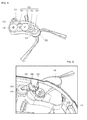
- Fig. 1 is a bottom view of an automatic cleaner according to a first embodiment.
- Fig. 2 is a view illustrating a state in which a side brush assembly is moved according to the first embodiment.
- an automatic cleaner 10 includes a casing 110 defining an outer appearance of automatic cleaner 10.
- Casing 110 may have a flat polyhedral shape, but is not limited thereto.
- a suction device for suctioning foreign substances and/or a collecting device (not shown) for collecting the suctioned foreign substances may be disposed within casing 110.
- a suction port 111 is defined in a bottom surface of casing 110.
- Suction port 111 functions as an inlet through which foreign substances are suctioned into casing 110, and in particular, into the collecting device by the suction device.
- Suction port 111 may be formed by partially cutting out the bottom surface of casing 110 or by forming an opening into the bottom surface of the casing 110.
- a main brush 120 is disposed on a position corresponding to that of suction port 111 within casing 110.
- Main brush 120 may pass through suction port 111 to contact foreign substances on a target cleaning surface, thereby removing the foreign substances.
- Main brush 120 is rotatably disposed on casing 110.
- a main driving part (not shown) providing a driving force for rotating main brush 120 is provided.
- a moving device 140 for moving casing 110 may be disposed on the casing 110.
- Moving device 140 may include a driving motor (not shown) disposed within casing 110 and one or more wheels rotated by the driving motor. In case of having only one wheel driven by the motor, at least one other wheel is provided which is not driven and which is just rotated during movement of the cleaner.
- At least one side brush assembly 200 is disposed on the of casing 110.
- the brush assembly 200 is disposed on a lower portion of the casing 110.
- a structure in which a plurality of side brush assembles 200 are disposed on casing 110 will be described as an example.
- Side brush assembly 200 may be movably disposed on the casing 110.
- side brush assembly 200 may be disposed under casing 110.
- at least one portion of side brush assembly 200 may be disposed within casing 110, and the other portion of side brush assembly 200 may be disposed outside casing 110.
- side brush assembly 200 may be rotatably operated.
- Side brush assembly 200 may function so that the suction device suctions foreign substances in a region outside the footprint of suction port 111.
- Side brush assembly 200 may include a movable member 210 rotatably connected to casing 110 by a first rotation shaft (see Fig. 4 , element 330) and a brush 230 rotatably connected to movable member 210 by a second rotation shaft 233.
- a portion of the movable member 210 may be disposed within the footprint of the casing 110 and/or inside of the casing 110.
- the casing may comprise a seating recess or storing recess which is provided in the casing 110.
- the seating recess may include a wall separating the space of the seating recess for accommodating the movable member 210 from the casing 110.
- the seating recess includes an opening at the side surface to allow the movable member 210 to rotate or move out of the seating recess when being rotated. When moving the movable member 210 it protrudes outside the footprint of casing 110 by rotation of movable member 210.
- movable member 210 may be rotated in a state where movable member 210 overlaps casing 110 as shown in Fig. 1 to protrude outside the footprint of casing 110. After rotating the movable member 210 from its first position to a second position to protrude outside the footprint of casing 110, a vertical overlapping area between the movable member 210 and the casing 110 is reduced compared to the situation when the movable member 210 is stored within or below the casing, e.g. in the seating recess or to the situation during moving the movable member 210 . Thereby, the moveable member 210 is well protected from being damaged when the cleaner is stored or charged.
- the entirety of movable member 210 may be disposed outside of but underneath casing 110.
- no seating recess is provided.
- a portion of movable member 210 may protrude from a side surface of the casing 110. In this case the movable member is covered by the casing and thereby protected from being damaged.
- the brush 230 may be disposed at least partly outside or below the casing 110 so that brush 230 is rotatable. Thus, the brush 230 can rotate independently whether the movable member 210 is in its first or second position.
- Brush 230 may include a brush holder 232 and a plurality of brushes 234 disposed on brush holder 232.
- the brush 230 is formed by at least one brush bundle each comprising a plurality of brushes 234. Preferably there is some space or distance between the plurality of brush bundles. In a preferred embodiment two or three brush bundles are used to form the brush 230. By using brush bundles having a distance to the next brush bundle the cleaning performance can be increased.
- Each brush bundle may include a brush bundle holder which is connected the brush holder 232.
- This brush bundle holder maybe formed by a flexible material and/or may have a predefined angled form to further increase cleaning performance.
- the brush bundle holder may fix a plurality single brushes to from the brush bundle to have round or rectangular cross-section.
- Fig. 3 is an exploded perspective view of the side brush assembly and a first driving device according to the first embodiment.
- Fig. 4 is a view illustrating a state in which the side brush assembly is installed on a casing according to the first embodiment.
- Fig. 5 is a perspective view of the side brush assembly.
- Fig. 6 is a view illustrating a state in which the side brush assembly is operated according to the first embodiment.
- automatic cleaner 10 may include a first driving device 300 generating a power for rotating movable member 210.
- First driving device 300 may include a first driving part 310 disposed in casing 110 and a first power transmission part for transmitting power of first driving part 310 into movable member 210.
- first driving part 310 may be a motor rotatable in both directions or a solenoid rotatable in both directions within a predetermined angle.
- the first power transmission part may function as a decelerator which decelerates a rotation speed of the motor to transmit the decelerated rotation to the movable member 210.
- the first power transmission part may include a first pulley 320 connected to first driving part 310, a second pulley 340 spaced apart from first pulley 320, and a belt 350 wound around first pulley 320 and second pulley 340.
- Second pulley 340 may have a diameter greater than that of first pulley 320.
- a shaft support part 150 for supporting a first rotation shaft 330 connected to second pulley 340 may be disposed on casing 110.
- the first power transmission part includes the plurality of pulleys and the belt in the first embodiment, the disclosure is not limited thereto.
- the first power transmission part may include a plurality of gears or a gear and link. That is, the first embodiment is not limited to the above-described structure of the first power transmission part.
- the first power transmission part may include a stepper motor to precisely rotate the movable member 210 by a predetermined angle out off the casing or the seating recess of the casing 110 or back below the casing or into the seating recess.
- a plurality of protrusions or markers 342 might be disposed on the second pulley 340 and are spaced apart from each other.
- a rotation angle of second pulley 340 (a portion of the power transmission part) may be detected by a detection part 400.
- detection part 400 may be a photo interrupter sensor.
- the first embodiment is not limited to a particular kind of detection part 400.
- Detection part 400 may successively detect the plurality of protrusions or markers 342 when second pulley 340 is rotated.
- a control part (not shown) may control the first driving part 310 on the basis of information outputted from detection part 400.
- the control part may control first driving part 310 to restrict a rotation range of movable member 210.
- detection part 400 and the plurality of protrusions or markers 342 of second pulley 340 may be referred to as a rotation range restriction part for restricting the rotation range of movable member 210.
- stepper motor By using a stepper motor no detection is required, since the stepper motor itself can be controlled to rotate a predefined angle.
- Detection part 400 may be fixed to shaft support part 150 by an installation part (not shown) or fixed to casing 110.
- First rotation shaft 330 may be disposed on a shaft fixing part 211 disposed on movable member 210.
- first rotation shaft 330 may pass through movable member 210 and be fixed to shaft fixing part 211.
- First rotation shaft 330 may be rotated by the rotation of second pulley 340.
- movable member 210 may be rotated together with first rotation shaft 330 by the rotation of first rotation shaft 330.
- Side brush assembly 200 may further include a second driving device for rotating the brush 230.
- the second driving device may include a second driving part 240 disposed on movable member 210 and a second power transmission part 250 for transmitting power of second driving part 240 to the brush 230.
- Second power transmission part 250 may function as a decelerator which decelerates a rotation speed of second driving part 240 to transmit the decelerated rotation to the brush 230.
- Second power transmission part 250 may include a plurality of gears.
- the plurality of gears 250 may include first to fourth gears 251, 252, 253, and 254.
- First gear 251 may be engaged with a motor gear (not shown).
- the first to third gears 251, 252, and 253 may include two gear parts having diameters different from each other. Also, one gear part having a relatively small diameter may be engaged with the adjacent other gear having a relatively large diameter.
- Second rotation shaft 233 connected to brush holder 232 is coupled to fourth gear 254.
- a hole 212 through which an electric wire (not shown) connected to second driving part 240 passes may be formed in the movable member 210.
- hole 212 may have an arc shape to prevent the electric wire from being damaged when movable member 210 is rotated.
- side brush assembly 200 When automatic cleaner 10 is not operated, i.e., when automatic cleaner 10 is stored or charged, side brush assembly 200 is disposed at a first position.
- the first position of side brush assembly 200 may be a position at which movable member 210 does not protrude outside the casing 110 as shown in Fig. 1 , e.g. outside the footprint of the casing 110
- side brush assembly 200 when side brush assembly 200 does not protrude outside the footprint of casing 110, a space required for storing automatic cleaner 10 may be reduced. Additionally, it may prevent brushes 234 and/or the moveable member 210 from being damaged when automatic cleaner 10 is stored.
- first driving part 310 is turned on and rotated in one direction.
- side brush assembly 200 is moved from the first position to a second position. That is, movable member 210 is rotated to move side brush assembly 200 from the first position to the second position.
- the second position of side brush assembly 200 may be a position at which at least one portion of movable member 210 protrudes outside the footprint of casing 110 as shown in Fig. 2 .
- second rotation shaft 233 is rotated around its axis to move the brushes in horizontal direction.
- detection part 400 While movable member 210 is rotated by first driving part 310, detection part 400 successively detects the plurality of protrusions or markers 342. Then, when the last or predetermined protrusion or markers 342 is detected, the control part turns the first driving part 310 off. That is, when the detection part 400 detects a protrusion or marker 342, a pulse may be generated. Thus, the control part determines the number of pulses to decide the on/off of first driving part 310.
- second driving part 240 is turned on, and thus, brush 230 is rotated.
- Brush 230 moves foreign substances in the region outside the footprint of suction port 111 towards the suction port 111, preferably below the suction port 111. Then, the foreign substances moved to the lower side of suction port 111 by the brush 230 are suctioned by the suction device.
- slip mechanism guarantees to force the movable member back into the first position, if the outer force is stronger than a predetermined value to thereby avoid a damage of the movable member 210.
- the slip mechanism is provided between second pulley 340 and belt 350 to cause a relative motion between second pulley 340 and belt 350.
- side brush assembly 200 may absorb an outer impact to prevent movable member 210 or first driving part 310 from being damaged.
- first driving part 310 When the operation of the suction device is to be stopped, first driving part 310 is turned on and rotated in the other direction. Thus, movable member 210 is rotated to move the automatic cleaner from the second position to the first position. Detection part 400 successively detects the plurality of protrusions or markers 342 while movable member 210 is rotated. When the predetermined protrusion 342 is detected, the control part turns first driving part 310 off. Also, when the operation of the suction device is stopped, the rotation of second driving part 240 is stopped, and thus, the rotation of brush 230 is stopped.
- movable member 210 since movable member 210 is disposed at the first position, it may prevent side brush assembly 200, particularly, brush 230 from being exposed to the outside of automatic cleaner 10.
- movable member 210 is stopped after movable member 210 is moved from the first position to the second position in the first embodiment, the disclosure is not limited thereto.
- movable member 210 may be repeatedly reciprocated between the first position and the second position.
- the movable member 210 might be rotated or moved between second and first position and vice versa, when the cleaner detects a corner or wall or obstacle or step to thereby improve the cleaning performance, since the area covered by the rotating brush and the moving or rotating movable member 210 is increased compared to the area covered by the rotating brush only.
- first driving part 310 is turned on when the suction device is operated in the first embodiment, the disclosure is not limited thereto. For example, when a corner/wall/step or obstacle is detected, first driving part 310 may be turned on.
- automatic cleaner 10 may be automatically operated in a general mode or be operated in the general mode by inputting a start command.
- the cleaning may be performed by the main brush.
- second driving part 240 may be operated in the general mode to rotate brush 230 in the state where movable member 210 is stopped.
- the first and second driving parts may not be operated or may be operated simultaneously.
- the control part may determine whether a corner/wall/step or obstacle is detected. Particularly, the control part may determine whether automatic cleaner 10 performs a wall following traveling (detects a wall) or whether a side obstacle is detected.
- the wall following traveling may represent that the automatic cleaner 10 is driven along a wall. Whether the wall following traveling is performed or the side obstacle is detected may be determined on the basis of information detected by an obstacle sensor (not shown).
- the cleaner might be equipped with one or more obstacle and/or distance sensors. If it is determined that automatic cleaner 10 performs the wall following traveling or the side obstacle is detected, the control part may determine whether a front obstacle (or a front wall) is detected. In general, since the corner corresponds to a portion at which a plurality of surfaces meet each other, when the wall or the side and front surfaces are detected, the control part may determine that a corner is detected.
- the control part may control automatic cleaner 10 so that automatic cleaner 10 performs a corner cleaning mode.
- the control part may turn first driving part 310 on.
- first driving part 310 When first driving part 310 is turned on, movable member 210 may be rotated or moved from the first position to the second position. This movement or rotation between the first and second position might be repeated predetermined times.
- the movable member 210 is rotated until a predetermined angle. Then, the first driving part 310 is turned off or driven in opposite direction
- the brush 230 disposed on movable member 210 may better approach the corner to effectively clean the corner.
- movable member 210 in the corner cleaning mode, may be repeatedly moved from the first position to the second position and from the second position to the first position. In the corner cleaning mode, moving device 140 may be maintained in a stop state.
- the cleaner 10 might be equipped with a cleaning state determination sensor which might be realized by at least one camera. Additionally or alternatively the cleaner 10 may include at least one dust determination sensor sensing the amount of dust sucked into the suction port 111.
- the control part may determine whether the corner is completely cleaned. For example, (1) after an operation type change time of the side brush assembly 200 exceeds a reference time or an operation type of the side brush assembly is changed, (2) when the rotation number of the brush (or the second driving part) exceeds a reference number or an operation time of the second driving part exceeds a reference time, or (3) when an operation type change number exceeds a reference number, it may be determined that the corner is completely cleaned.
- whether the corner is completely cleaned may be determined by a sensor for detecting a cleaned state. For example, whether the corner is completely cleaned may be determined on the basis of a corner image photographed by a camera or may be determined on the basis of an amount of dusts suctioned through the suction port which is detected using a sensor.
- the present disclosure is not limited to a method for determining whether the corner is completely cleaned.
- automatic cleaner 10 may be operated again in the general mode. That is, movable member 210 is stopped at the first position.
- Fig. 7 is a view illustrating a state in which a side brush assembly is installed on a casing according to a second embodiment.
- the second embodiment is equivalent to the first embodiment except for a kind of detection part. Thus, only specific portions of the second embodiment will be described below.
- an automatic cleaner according to the second embodiment may include a plurality of detection parts 410 and 420 for detecting a rotation angle of a second pulley 340.
- the plurality of detection parts 410 and 420 may include a first detection part 410 and a second detection part 420 spaced from first detection part 410.
- detection parts 410 and 420 may be micro switches.
- a protrusion 344 may be disposed on second pulley 340. Protrusion 344 presses a contact point of first detection part 410 when second pulley 340 is rotated in one direction. On the other hand, protrusion 344 presses a contact point of second detection part 420 when second pulley 340 is rotated in the opposite direction.
- first driving part 310 When a first driving part 310 is turned on and thus rotated in one direction, a first pulley 320 and second pulley 340 are rotated in one direction. Since second pulley 340 is rotated in the one direction, a first rotation shaft 330 and a movable member 210 are rotated in one direction.
- protrusion 344 presses the contact point of second detection part 420 while second pulley 340 is rotated in the one direction, a turn-on signal occurs in second detection part 420. Then, a control part receives a signal to turn first driving part 310 off.
- first driving part 310 when first driving part 310 is turned on to return movable member 210 to the first position, first driving part 310 is rotated in the opposite direction.
- first driving part 310 is rotated in the opposite direction to move or rotate the movable member back to first position
- first pulley 320 and the second pulley 340 are rotated both in same but in the opposite direction compared to the movement or rotation from the first to the second position.
- second pulley 340 is rotated in the opposite direction, the first rotation shaft 330 and the movable member 210 are rotated in the opposite direction.
- detection parts 410 and 420 and protrusion 344 of second pulley 340 may be referred to as a rotation range restriction part for restricting a rotation range of movable member 210.
- protrusion(s) of the two above-described embodiments are disposed on second pulley 340, and detection parts 400, 410, and 420 detect protrusion(s) in the above-described two embodiments, the disclosure is not limited thereto.
- the protrusion(s) may be disposed on movable member 210.
- Fig. 8 is a bottom view of an automatic cleaner according to a third embodiment.
- the third embodiment is equivalent to the first embodiment except for an operation type of a side brush assembly. Thus, only specific portions of the current embodiment will be described below.
- a side brush assembly 500 i.e., a movable member may be linearly movably disposed on a casing 110.
- side brush assembly 500 may be linearly movably disposed on casing 110, preferably in a diagonal direction. That is to say, the driving member may be linearly moved in a direction crossing a rotation shaft of a wheel constituting a moving device 140.
- casing 110 When casing 110 has a circular shape, it may be difficult to smoothly clean a portion angled at an angle of about 45° from a center of casing 110. Since a corner in a cleaning area is disposed at an angle of about 45° from the center of casing 110, the movable member may be linearly moved in a state where the movable member is inclined or positioned at an angle of about 45° with respect to a rotation shaft of the wheel constituting moving device 140 to effectively clean the corner.
- the third embodiment is not limited to an angle between a moving path of the movable member and the wheel.
- side brush assembly 500 since other components constituting side brush assembly 500 are equal to those of the first or second embodiments, their detailed descriptions will be omitted. According to the described embodiments, the operation type of the side brush assembly is changed during the cleaning of the corner to effectively clean the corner by the side brush assembly. Also, it may prevent the brush from being damaged, and the side brush assembly may be safely stored.
Abstract
Description
- The present disclosure relates to an automatic cleaner. In general, cleaners are home appliances which suction and remove foreign substances from a cleaning surface. Recently, automatic cleaners, that is, cleaners for automatically performing a cleaning operation, have begun to be more frequently utilized. The automatic cleaner suctions and removes foreign substances from a floor while being moved by the driving force of a motor powered by a battery.
- A moving device is installed on a casing which defines the outer appearance of a general automatic cleaner. The moving device moves the automatic cleaner in a predetermined direction to suction foreign substances from a floor. To this end, a suction port for suctioning the foreign substances from the floor is disposed in a bottom surface of the casing. A main brush which directly contacts the foreign substances to suction the foreign substances through the suction port may be disposed on the suction port.
- However, the automatic cleaner suctions only foreign substances in a region corresponding to a lower side of the casing, substantially, a region corresponding to a lower side of the suction port (e.g., under the suction port). Thus, it may be difficult to effectively clean a region outside the footprint of the suction port.
- To prevent this difficulty, a side brush is disposed on the bottom surface of the casing. At any one time, at least one portion of the side brush extends outside the footprint of the casing.
- The side brush is rotated with respect to the casing to move foreign substances in a region outside the footprint of the casing, specifically, outside the footprint of the suction port toward the suction port.
- However, such an automatic cleaner may have following limitations.
- As described above, foreign substances located in the region outside the footprint of the suction port are suctioned through the suction port by rotating the side brush. Thus, the more the side brush is increased in length, the more a cleaning area of the automatic cleaner is substantially increased. However, when the side brush is increased in length, the side brush may be damaged while cleaning or being stored. In addition, when the side brush is increased in length, a region occupied by the automatic cleaner may be increased. Thus, it may be inconvenient to store the automatic cleaner.
- In one embodiment, an automatic cleaner includes: a casing having a suction port in a bottom portion of the casing through which foreign substances are suctioned; a moving device that moves the casing; and a side brush assembly movably installed on the casing, wherein the side brush assembly comprises: a movable member movably disposed on the casing; a first driving device that generates power for moving the movable member; a brush rotatably mounted on the movable member; and a second driving device that generates power for rotating the brush.
- In a further embodiment, an automatic cleaner includes: a casing having a suction port in a bottom portion of the casing through which foreign substances are suctioned; a moving device that moves the casing; and a side brush assembly movably installed on the casing, wherein the side brush assembly comprises: a movable member movably disposed on the casing; a first driving device that generates power to move the movable member; a brush rotatably mounted on the movable member and including at least two brush bundles extending from a brush holder, the brush bundles are spaced apart to each other by a distance bigger than a size of the brush bundle and a second driving device that generates power to rotate the brush.
- In a further embodiment, an automatic cleaner includes: a casing having a suction port in a bottom portion of the casing through which foreign substances are suctioned; a moving device that moves the casing; and a side brush assembly movably installed on the casing, wherein the side brush assembly comprises: a movable member movably disposed on the casing; a first driving device that generates power to move the movable member; a brush rotatably mounted on the movable member and a second driving device that generates power to rotate the brush, wherein in a first position the movable member is fully covered by the casing and in a second position the movable member is protruding at least partly outside the casing.
- In a further embodiment, an automatic cleaner includes: a casing having a suction port in a bottom portion of the casing through which foreign substances are suctioned; a moving device that moves the casing; and a side brush assembly movably installed on the casing, wherein the side brush assembly comprises: a movable member movably disposed on the casing; a first driving device that generates power for moving the movable member; a brush rotatably mounted on the movable member; and a second driving device that generates power for rotating the brush; and a rotation range restriction part that restricts a rotation range of the movable member.
- Preferably, the first driving device comprises a first driving part and a decelerator that decelerates a rotation rate of the first driving part.
- Preferably, the first driving part comprises at least one of: a motor rotatable in both directions, a solenoid or stepper motor, each rotatable in both directions within a predetermined range.
- Preferably, the decelerator comprises a plurality of pulleys and a belt wound around the plurality of pulleys.
- Preferably, the plurality of pulleys comprise a first pulley connected to the first driving part; and a second pulley connected to a first rotation shaft disposed on the movable member, wherein the second pulley has a diameter greater than that of the first pulley.
- Preferably, the movable member is movable between a first position and a second position.
- Preferably, the automatic cleaner may comprise a rotation range restriction part that restricts a rotation range of the movable member.
- Preferably, the rotation range restriction part comprises at least one detection part that detects rotation of a portion of the power transmission part or the movable member.
- Preferably, the movable member is stopped after the movable member is detected by the rotation range restriction part to have moved from a first position to a second position.
- Preferably, the movable member is reciprocated between a first position and a second position based on rotation detection by the rotation range restriction part.
- Preferably, the second driving device is disposed on the movable member and moved together with the movable member.
- Preferably, the second driving device comprises a second driving part and a decelerator decelerating a rotating rate of the second driving part.
- Preferably, the decelerator comprises a plurality of gears.
- Preferably, when the movable member is moved, a rotation shaft of the brush is moved in a horizontal direction.
- Preferably, the movable member is received within the casing, and when the first driving part is turned on, the movable member received within the casing protrudes laterally from the casing.
- Preferably, the movable member is disposed under the casing, and when the first driving part is turned on, the movable member disposed under the casing protrudes laterally from the casing.
- Preferably, the brush includes at least three brush bundles, each brush bundled is fixed in a brush bundle holder, which is fixed to the brush holder
- Preferably, the brush bundle holder is made of flexible material.
- Preferably, the brush bundle holder has a predetermined angled form.
- Preferably, the casing includes a seating recess for accommodating the movable member.
- Preferably, the casing has a distance to the floor allowing the movable member and the brush to freely rotate or move.
- Preferably, the cleaner comprises at least one of: one or more obstacle and/or distance sensors; a cleaning state determination sensor determining the cleaning state of the floor to be cleaned; a dust determination sensor sensing the amount of dust sucked into the suction port .
- The movable member is disposed under the casing, and when the first driving part is turned on, the movable member disposed under the casing protrudes laterally from the casing.
- In another embodiment, an automatic cleaner, comprises a casing having a suction port through which foreign substances are suctioned; a moving device that moves the casing; and a first side brush assembly movably installed on the casing, wherein the first side brush assembly moves between a first position and a second position.
- The automatic cleaner comprises: a second side brush assembly fixedly installed on the casing.
- In further another embodiment, an automatic cleaner, comprises a casing having a suction port in a bottom portion of the casing through which foreign substances are suctioned; a moving device that moves the casing; and a side brush assembly movably installed on the casing, wherein the side brush assembly comprises: a movable member movably disposed on the casing; a first driving device comprising a first driving part and a decelerator that provide power to move the movable member; a brush rotatably mounted on the movable member; and a second driving device comprising a second driving part and a decelerator that provide power to rotate the brush.
- The automatic cleaner further comprises a rotation range restriction part, including at least one detection part that detects rotation of a portion of the movable member, that restricts a rotation range of the movable member.
- The details of one or more embodiments are set forth in the accompanying drawings and the description below. Other features will be apparent from the description and drawings, and from the claims.
-
-
Fig. 1 is a bottom view illustrating an automatic cleaner according to a first embodiment. -
Fig. 2 is a view illustrating a state in which a side brush assembly is moved according to the first embodiment. -
Fig. 3 is an exploded perspective view illustrating the side brush assembly and a first driving device according to the first embodiment. -
Fig. 4 is a view illustrating a state in which the side brush assembly is installed on a casing according to the first embodiment. -
Fig. 5 is a perspective view illustrating the side brush assembly. -
Fig. 6 is a view illustrating a state in which the side brush assembly is operated according to the first embodiment. -
Fig. 7 is a view illustrating a state in which a side brush assembly is installed on a casing according to a second embodiment. -
Fig. 8 is a bottom view illustrating an automatic cleaner according to a third embodiment. - Reference will now be made in detail to the embodiments of the present disclosure, examples of which are illustrated in the accompanying drawings.
-
Fig. 1 is a bottom view of an automatic cleaner according to a first embodiment.Fig. 2 is a view illustrating a state in which a side brush assembly is moved according to the first embodiment. - Referring to
Figs. 1 and2 , an automatic cleaner 10 according to the first embodiment includes acasing 110 defining an outer appearance ofautomatic cleaner 10. Casing 110 may have a flat polyhedral shape, but is not limited thereto. - Various components constituting
automatic cleaner 10 may be installed withincasing 110. For example, a suction device (not shown) for suctioning foreign substances and/or a collecting device (not shown) for collecting the suctioned foreign substances may be disposed withincasing 110. - A
suction port 111 is defined in a bottom surface ofcasing 110.Suction port 111 functions as an inlet through which foreign substances are suctioned intocasing 110, and in particular, into the collecting device by the suction device.Suction port 111 may be formed by partially cutting out the bottom surface ofcasing 110 or by forming an opening into the bottom surface of thecasing 110. - A
main brush 120 is disposed on a position corresponding to that ofsuction port 111 withincasing 110.Main brush 120 may pass throughsuction port 111 to contact foreign substances on a target cleaning surface, thereby removing the foreign substances.Main brush 120 is rotatably disposed oncasing 110. Also, a main driving part (not shown) providing a driving force for rotatingmain brush 120 is provided. - A moving
device 140 for movingcasing 110 may be disposed on thecasing 110. Movingdevice 140 may include a driving motor (not shown) disposed withincasing 110 and one or more wheels rotated by the driving motor. In case of having only one wheel driven by the motor, at least one other wheel is provided which is not driven and which is just rotated during movement of the cleaner. - At least one
side brush assembly 200 is disposed on the ofcasing 110. Preferably, thebrush assembly 200 is disposed on a lower portion of thecasing 110. In the first embodiment, a structure in which a plurality of side brush assembles 200 are disposed oncasing 110 will be described as an example. -
Side brush assembly 200 may be movably disposed on thecasing 110. For example,side brush assembly 200 may be disposed undercasing 110. Particularly, at least one portion ofside brush assembly 200 may be disposed withincasing 110, and the other portion ofside brush assembly 200 may be disposed outsidecasing 110. Further,side brush assembly 200 may be rotatably operated. -
Side brush assembly 200 may function so that the suction device suctions foreign substances in a region outside the footprint ofsuction port 111. -
Side brush assembly 200 may include amovable member 210 rotatably connected to casing 110 by a first rotation shaft (seeFig. 4 , element 330) and abrush 230 rotatably connected tomovable member 210 by asecond rotation shaft 233. - A portion of the
movable member 210 may be disposed within the footprint of thecasing 110 and/or inside of thecasing 110. To provide a reliable storing of themovable member 210, the casing may comprise a seating recess or storing recess which is provided in thecasing 110. The seating recess may include a wall separating the space of the seating recess for accommodating themovable member 210 from thecasing 110. The seating recess includes an opening at the side surface to allow themovable member 210 to rotate or move out of the seating recess when being rotated. When moving themovable member 210 it protrudes outside the footprint ofcasing 110 by rotation ofmovable member 210. That is,movable member 210 may be rotated in a state wheremovable member 210 overlaps casing 110 as shown inFig. 1 to protrude outside the footprint ofcasing 110. After rotating themovable member 210 from its first position to a second position to protrude outside the footprint ofcasing 110, a vertical overlapping area between themovable member 210 and thecasing 110 is reduced compared to the situation when themovable member 210 is stored within or below the casing, e.g. in the seating recess or to the situation during moving themovable member 210 . Thereby, themoveable member 210 is well protected from being damaged when the cleaner is stored or charged. - In another example, the entirety of
movable member 210 may be disposed outside of but underneathcasing 110. Here, no seating recess is provided. Thus, whenmovable member 210 is rotated or moved, a portion ofmovable member 210 may protrude from a side surface of thecasing 110. In this case the movable member is covered by the casing and thereby protected from being damaged. - When the
movable member 210 is disposed withincasing 110, thebrush 230 may be disposed at least partly outside or below thecasing 110 so thatbrush 230 is rotatable. Thus, thebrush 230 can rotate independently whether themovable member 210 is in its first or second position. -
Brush 230 may include abrush holder 232 and a plurality ofbrushes 234 disposed onbrush holder 232. Thebrush 230 is formed by at least one brush bundle each comprising a plurality ofbrushes 234. Preferably there is some space or distance between the plurality of brush bundles. In a preferred embodiment two or three brush bundles are used to form thebrush 230. By using brush bundles having a distance to the next brush bundle the cleaning performance can be increased. Each brush bundle may include a brush bundle holder which is connected thebrush holder 232. This brush bundle holder maybe formed by a flexible material and/or may have a predefined angled form to further increase cleaning performance. The brush bundle holder may fix a plurality single brushes to from the brush bundle to have round or rectangular cross-section. -
Fig. 3 is an exploded perspective view of the side brush assembly and a first driving device according to the first embodiment.Fig. 4 is a view illustrating a state in which the side brush assembly is installed on a casing according to the first embodiment.Fig. 5 is a perspective view of the side brush assembly.Fig. 6 is a view illustrating a state in which the side brush assembly is operated according to the first embodiment. - Referring to
Figs. 3 to 5 ,automatic cleaner 10 may include afirst driving device 300 generating a power for rotatingmovable member 210. - First driving
device 300 may include afirst driving part 310 disposed incasing 110 and a first power transmission part for transmitting power of first drivingpart 310 intomovable member 210. For example, first drivingpart 310 may be a motor rotatable in both directions or a solenoid rotatable in both directions within a predetermined angle. - The first power transmission part may function as a decelerator which decelerates a rotation speed of the motor to transmit the decelerated rotation to the
movable member 210. - The first power transmission part may include a
first pulley 320 connected to first drivingpart 310, asecond pulley 340 spaced apart fromfirst pulley 320, and abelt 350 wound aroundfirst pulley 320 andsecond pulley 340.Second pulley 340 may have a diameter greater than that offirst pulley 320. Ashaft support part 150 for supporting afirst rotation shaft 330 connected tosecond pulley 340 may be disposed oncasing 110. - Although the first power transmission part includes the plurality of pulleys and the belt in the first embodiment, the disclosure is not limited thereto. For example, the first power transmission part may include a plurality of gears or a gear and link. That is, the first embodiment is not limited to the above-described structure of the first power transmission part.
- Alternatively the first power transmission part may include a stepper motor to precisely rotate the
movable member 210 by a predetermined angle out off the casing or the seating recess of thecasing 110 or back below the casing or into the seating recess. - A plurality of protrusions or
markers 342 might be disposed on thesecond pulley 340 and are spaced apart from each other. A rotation angle of second pulley 340 (a portion of the power transmission part) may be detected by adetection part 400. For example,detection part 400 may be a photo interrupter sensor. The first embodiment is not limited to a particular kind ofdetection part 400.Detection part 400 may successively detect the plurality of protrusions ormarkers 342 whensecond pulley 340 is rotated. A control part (not shown) may control thefirst driving part 310 on the basis of information outputted fromdetection part 400. The control part may control first drivingpart 310 to restrict a rotation range ofmovable member 210. - That is, in the first embodiment,
detection part 400 and the plurality of protrusions ormarkers 342 ofsecond pulley 340 may be referred to as a rotation range restriction part for restricting the rotation range ofmovable member 210. - By using a stepper motor no detection is required, since the stepper motor itself can be controlled to rotate a predefined angle.
-
Detection part 400 may be fixed toshaft support part 150 by an installation part (not shown) or fixed tocasing 110. -
First rotation shaft 330 may be disposed on ashaft fixing part 211 disposed onmovable member 210. Here,first rotation shaft 330 may pass throughmovable member 210 and be fixed toshaft fixing part 211.First rotation shaft 330 may be rotated by the rotation ofsecond pulley 340. Also,movable member 210 may be rotated together withfirst rotation shaft 330 by the rotation offirst rotation shaft 330. -
Side brush assembly 200 may further include a second driving device for rotating thebrush 230. The second driving device may include asecond driving part 240 disposed onmovable member 210 and a secondpower transmission part 250 for transmitting power ofsecond driving part 240 to thebrush 230. Secondpower transmission part 250 may function as a decelerator which decelerates a rotation speed ofsecond driving part 240 to transmit the decelerated rotation to thebrush 230. - Second
power transmission part 250 may include a plurality of gears. The plurality ofgears 250 may include first tofourth gears -
First gear 251 may be engaged with a motor gear (not shown). The first tothird gears Second rotation shaft 233 connected to brushholder 232 is coupled tofourth gear 254. - A
hole 212 through which an electric wire (not shown) connected tosecond driving part 240 passes may be formed in themovable member 210. Here, sincemovable member 210 is rotatable,hole 212 may have an arc shape to prevent the electric wire from being damaged whenmovable member 210 is rotated. - Hereinafter, an operation of
side brush assembly 200 will be described. - When automatic cleaner 10 is not operated, i.e., when
automatic cleaner 10 is stored or charged,side brush assembly 200 is disposed at a first position. In the first embodiment, the first position ofside brush assembly 200 may be a position at whichmovable member 210 does not protrude outside thecasing 110 as shown inFig. 1 , e.g. outside the footprint of thecasing 110 - As described above, when
side brush assembly 200 does not protrude outside the footprint ofcasing 110, a space required for storingautomatic cleaner 10 may be reduced. Additionally, it may preventbrushes 234 and/or themoveable member 210 from being damaged whenautomatic cleaner 10 is stored. - When automatic cleaner 10 is turned on to perform the cleaning operation in a state of
Fig. 1 , an operation of the suction device starts to suction foreign substances throughsuction port 111. Also, movingdevice 140 is operated to allow the cleaner to perform the cleaning operation while the cleaner is moved. - Referring to
Figs. 2 and5 , when an operation of the suction device starts, first drivingpart 310 is turned on and rotated in one direction. Thus,side brush assembly 200 is moved from the first position to a second position. That is,movable member 210 is rotated to moveside brush assembly 200 from the first position to the second position. - Here, the second position of
side brush assembly 200 may be a position at which at least one portion ofmovable member 210 protrudes outside the footprint ofcasing 110 as shown inFig. 2 . Whenmovable member 210 is moved from the first position to the second position,second rotation shaft 233 is rotated around its axis to move the brushes in horizontal direction. - While
movable member 210 is rotated by first drivingpart 310,detection part 400 successively detects the plurality of protrusions ormarkers 342. Then, when the last or predetermined protrusion ormarkers 342 is detected, the control part turns thefirst driving part 310 off. That is, when thedetection part 400 detects a protrusion ormarker 342, a pulse may be generated. Thus, the control part determines the number of pulses to decide the on/off of first drivingpart 310. - Also, when the operation of the suction device starts, second driving
part 240 is turned on, and thus,brush 230 is rotated.Brush 230 moves foreign substances in the region outside the footprint ofsuction port 111 towards thesuction port 111, preferably below thesuction port 111. Then, the foreign substances moved to the lower side ofsuction port 111 by thebrush 230 are suctioned by the suction device. - Here, while or after
movable member 210 is moved into the second position, when an outer force is applied tomovable member 210, a slip phenomenon may occur. This slip mechanism guarantees to force the movable member back into the first position, if the outer force is stronger than a predetermined value to thereby avoid a damage of themovable member 210. Preferably, the slip mechanism is provided betweensecond pulley 340 andbelt 350 to cause a relative motion betweensecond pulley 340 andbelt 350. Thus,side brush assembly 200 may absorb an outer impact to preventmovable member 210 or first drivingpart 310 from being damaged. - Next, when the cleaning operation of
automatic cleaner 10 is stopped, operation of the suction device is likewise stopped. When automatic cleaner 10 is disposed at a predetermined position, e.g., a position at whichautomatic cleaner 10 is charged or stored, operation of movingdevice 140 is likewise stopped. - When the operation of the suction device is to be stopped, first driving
part 310 is turned on and rotated in the other direction. Thus,movable member 210 is rotated to move the automatic cleaner from the second position to the first position.Detection part 400 successively detects the plurality of protrusions ormarkers 342 whilemovable member 210 is rotated. When thepredetermined protrusion 342 is detected, the control part turns first drivingpart 310 off. Also, when the operation of the suction device is stopped, the rotation ofsecond driving part 240 is stopped, and thus, the rotation ofbrush 230 is stopped. - Also, since
movable member 210 is disposed at the first position, it may preventside brush assembly 200, particularly,brush 230 from being exposed to the outside ofautomatic cleaner 10. - Although
movable member 210 is stopped aftermovable member 210 is moved from the first position to the second position in the first embodiment, the disclosure is not limited thereto. For example,movable member 210 may be repeatedly reciprocated between the first position and the second position. Preferably, themovable member 210 might be rotated or moved between second and first position and vice versa, when the cleaner detects a corner or wall or obstacle or step to thereby improve the cleaning performance, since the area covered by the rotating brush and the moving or rotatingmovable member 210 is increased compared to the area covered by the rotating brush only. - Also, although the
first driving part 310 is turned on when the suction device is operated in the first embodiment, the disclosure is not limited thereto. For example, when a corner/wall/step or obstacle is detected, first drivingpart 310 may be turned on. - Particularly, after
automatic cleaner 10 is turned on,automatic cleaner 10 may be automatically operated in a general mode or be operated in the general mode by inputting a start command. In the general mode ofautomatic cleaner 10, whenautomatic cleaner 10 is moved by movingdevice 140, the cleaning may be performed by the main brush. In some cases, second drivingpart 240 may be operated in the general mode to rotatebrush 230 in the state wheremovable member 210 is stopped. Alternatively, in the general mode, the first and second driving parts may not be operated or may be operated simultaneously. - When automatic cleaner 10 is operated in the general mode, the control part may determine whether a corner/wall/step or obstacle is detected. Particularly, the control part may determine whether automatic cleaner 10 performs a wall following traveling (detects a wall) or whether a side obstacle is detected. The wall following traveling may represent that the
automatic cleaner 10 is driven along a wall. Whether the wall following traveling is performed or the side obstacle is detected may be determined on the basis of information detected by an obstacle sensor (not shown). - The cleaner might be equipped with one or more obstacle and/or distance sensors. If it is determined that
automatic cleaner 10 performs the wall following traveling or the side obstacle is detected, the control part may determine whether a front obstacle (or a front wall) is detected. In general, since the corner corresponds to a portion at which a plurality of surfaces meet each other, when the wall or the side and front surfaces are detected, the control part may determine that a corner is detected. - If it is determined that a corner is detected, the control part may control automatic cleaner 10 so that
automatic cleaner 10 performs a corner cleaning mode. In the corner cleaning mode, the control part may turn first drivingpart 310 on. When first drivingpart 310 is turned on,movable member 210 may be rotated or moved from the first position to the second position. This movement or rotation between the first and second position might be repeated predetermined times. Here, themovable member 210 is rotated until a predetermined angle. Then, thefirst driving part 310 is turned off or driven in opposite direction - When
movable member 210 is withdrawn in the corner cleaning mode, thebrush 230 disposed onmovable member 210 may better approach the corner to effectively clean the corner. - In another example, in the corner cleaning mode,
movable member 210 may be repeatedly moved from the first position to the second position and from the second position to the first position. In the corner cleaning mode, movingdevice 140 may be maintained in a stop state. - The cleaner 10 might be equipped with a cleaning state determination sensor which might be realized by at least one camera. Additionally or alternatively the cleaner 10 may include at least one dust determination sensor sensing the amount of dust sucked into the
suction port 111. - Next, the control part may determine whether the corner is completely cleaned. For example, (1) after an operation type change time of the
side brush assembly 200 exceeds a reference time or an operation type of the side brush assembly is changed, (2) when the rotation number of the brush (or the second driving part) exceeds a reference number or an operation time of the second driving part exceeds a reference time, or (3) when an operation type change number exceeds a reference number, it may be determined that the corner is completely cleaned. Alternatively, whether the corner is completely cleaned may be determined by a sensor for detecting a cleaned state. For example, whether the corner is completely cleaned may be determined on the basis of a corner image photographed by a camera or may be determined on the basis of an amount of dusts suctioned through the suction port which is detected using a sensor. The present disclosure is not limited to a method for determining whether the corner is completely cleaned. - When it is determined that the corner is completely cleaned,
automatic cleaner 10 may be operated again in the general mode. That is,movable member 210 is stopped at the first position. -
Fig. 7 is a view illustrating a state in which a side brush assembly is installed on a casing according to a second embodiment. - The second embodiment is equivalent to the first embodiment except for a kind of detection part. Thus, only specific portions of the second embodiment will be described below.
- Referring to
Fig. 7 , an automatic cleaner according to the second embodiment may include a plurality ofdetection parts second pulley 340. - The plurality of
detection parts first detection part 410 and asecond detection part 420 spaced fromfirst detection part 410. For example,detection parts - A
protrusion 344 may be disposed onsecond pulley 340.Protrusion 344 presses a contact point offirst detection part 410 whensecond pulley 340 is rotated in one direction. On the other hand,protrusion 344 presses a contact point ofsecond detection part 420 whensecond pulley 340 is rotated in the opposite direction. - When a
first driving part 310 is turned on and thus rotated in one direction, afirst pulley 320 andsecond pulley 340 are rotated in one direction. Sincesecond pulley 340 is rotated in the one direction, afirst rotation shaft 330 and amovable member 210 are rotated in one direction. Whenprotrusion 344 presses the contact point ofsecond detection part 420 whilesecond pulley 340 is rotated in the one direction, a turn-on signal occurs insecond detection part 420. Then, a control part receives a signal to turn first drivingpart 310 off. - On the other hand, when first driving
part 310 is turned on to returnmovable member 210 to the first position, first drivingpart 310 is rotated in the opposite direction. When thefirst driving part 310 is rotated in the opposite direction to move or rotate the movable member back to first position, thefirst pulley 320 and thesecond pulley 340 are rotated both in same but in the opposite direction compared to the movement or rotation from the first to the second position. Also, since thesecond pulley 340 is rotated in the opposite direction, thefirst rotation shaft 330 and themovable member 210 are rotated in the opposite direction. When theprotrusion 344 presses the contact point offirst detection part 410 whilesecond pulley 340 is rotated in the opposite direction, a signal is generated at thefirst detection part 410. Then, the control part receives this signal to turn thefirst driving part 310 off. - In the second embodiment,
detection parts protrusion 344 ofsecond pulley 340 may be referred to as a rotation range restriction part for restricting a rotation range ofmovable member 210. - Although protrusion(s) of the two above-described embodiments are disposed on
second pulley 340, anddetection parts movable member 210. -
Fig. 8 is a bottom view of an automatic cleaner according to a third embodiment. The third embodiment is equivalent to the first embodiment except for an operation type of a side brush assembly. Thus, only specific portions of the current embodiment will be described below. - Referring to
Fig. 8 , aside brush assembly 500 according to the third embodiment, i.e., a movable member may be linearly movably disposed on acasing 110. For example,side brush assembly 500 may be linearly movably disposed oncasing 110, preferably in a diagonal direction. That is to say, the driving member may be linearly moved in a direction crossing a rotation shaft of a wheel constituting a movingdevice 140. - When casing 110 has a circular shape, it may be difficult to smoothly clean a portion angled at an angle of about 45° from a center of
casing 110. Since a corner in a cleaning area is disposed at an angle of about 45° from the center ofcasing 110, the movable member may be linearly moved in a state where the movable member is inclined or positioned at an angle of about 45° with respect to a rotation shaft of the wheel constituting movingdevice 140 to effectively clean the corner. However, the third embodiment is not limited to an angle between a moving path of the movable member and the wheel. - Also, since other components constituting
side brush assembly 500 are equal to those of the first or second embodiments, their detailed descriptions will be omitted. According to the described embodiments, the operation type of the side brush assembly is changed during the cleaning of the corner to effectively clean the corner by the side brush assembly. Also, it may prevent the brush from being damaged, and the side brush assembly may be safely stored. - Although embodiments have been described with reference to a number of illustrative embodiments thereof, it should be understood that numerous other modifications and embodiments can be devised by those skilled in the art that will fall within the scope of the principles of this disclosure. More particularly, variations and modifications are possible in the component parts and/or arrangements of the subject combination arrangement within the scope of the disclosure, the drawings, and the appended claims. In addition to variations and modifications in the component parts and/or arrangements, alternative uses will also be apparent to those skilled in the art.
Claims (18)
- An automatic cleaner (10) comprising:a casing (110) having a suction port (111) in a bottom portion of the casing (110) through which foreign substances are suctioned;a moving device (140) that moves the casing (110); anda side brush assembly (200) movably installed on the casing (110),wherein the side brush assembly (200) comprises:a movable member (210) movably disposed on the casing (110);a first driving device (300) that generates power to move the movable member (210);a brush (230) rotatably mounted on the movable member (210) and including at least two brush bundles extending from a brush holder (232), the brush bundles are spaced apart to each other by a distance bigger than a size of the brush bundle anda second driving device that generates power to rotate the brush (230).
- The automatic cleaner of claim 1, wherein the first driving device (300) comprises a first driving part (310) and a decelerator that decelerates a rotation rate of the first driving part (310).
- The automatic cleaner of claim 1 or 2, wherein the first driving part (310) comprises at least one of: a motor rotatable in both directions, a solenoid or stepper motor, each rotatable in both directions within a predetermined range.
- The automatic cleaner of claim 2 or 3, wherein the decelerator comprises a plurality of pulleys (320, 340) and a belt (350) wound around the plurality of pulleys (320, 340).
- The automatic cleaner as claimed in any one of the preceding claims, wherein the movable member (210) is movable between a first position and a second position.
- The automatic cleaner as claimed in any one of the preceding claims, wherein in a first position the movable member is fully covered by the casing (110) and in a second position the movable member (210) is protruding at least partly outside the casing (110).
- The automatic cleaner as claimed in any one of the preceding claims, further comprising a rotation range restriction part that restricts a rotation range of the movable member (210).
- The automatic cleaner of claim 7, wherein the rotation range restriction part comprises at least one detection part (410, 420) that detects rotation of a portion of the power transmission part (250) or the movable member (210).
- The automatic cleaner of claim 7 or 8, wherein the movable member (210) is stopped after the movable member (210) is detected by the rotation range restriction part to have moved from a first position to a second position.
- The automatic cleaner as claimed in any one of the preceding claims 6 - 9, wherein the movable member (210) is reciprocated between a first position and a second position based on rotation detection by the rotation range restriction part.
- The automatic cleaner as claimed in any one of the preceding claims, wherein the second driving device is disposed on the movable member (210) and moved together with the movable member (210).
- The automatic cleaner as claimed in any one of the preceding claims, wherein the second driving device comprises a second driving part (240) and a decelerator decelerating a rotating rate of the second driving part (240).
- The automatic cleaner as claimed in any one of the preceding claims, wherein, when the movable member (210) is moved, a rotation shaft (233) of the brush (230) is moved in a horizontal direction.
- The automatic cleaner as claimed in any one of the preceding claims, wherein the movable member (210) is received within the casing (110), and when the first driving part (300) is turned on, the movable member (210) received within the casing (110) protrudes laterally from the casing (110) or the movable member (210) is disposed under the casing (110), and when the first driving part (300) is turned on, the movable member (210) disposed under the casing (110) protrudes laterally from the casing (110).
- The automatic cleaner as claimed in any one of the preceding claims, wherein the brush includes at least three brush bundles, each brush bundled is fixed in a brush bundle holder, which is fixed to the brush holder (232), the brush bundle holder is made of flexible material and has a predetermined angled form.
- The automatic cleaner as claimed in any one of the preceding claims, wherein the casing includes a seating recess for accommodating the movable member (210).
- The automatic cleaner as claimed in any one of the preceding claims, wherein the casing has a distance to the floor allowing the movable member (210) and the brush (230) to freely rotate or move.
- The automatic cleaner as claimed in any one of the preceding claims, wherein the cleaner comprises at least one of:- one or more obstacle and/or distance sensors;- a cleaning state determination sensor determining the cleaning state of the floor to be cleaned;- a dust determination sensor sensing the amount of dust sucked into the suction port (111).
Applications Claiming Priority (1)
| Application Number | Priority Date | Filing Date | Title |
|---|---|---|---|
| KR1020120115950A KR102022104B1 (en) | 2012-10-18 | 2012-10-18 | Automatic cleaner |
Publications (3)
| Publication Number | Publication Date |
|---|---|
| EP2721984A2 true EP2721984A2 (en) | 2014-04-23 |
| EP2721984A3 EP2721984A3 (en) | 2015-06-17 |
| EP2721984B1 EP2721984B1 (en) | 2019-09-04 |
Family
ID=49385145
Family Applications (1)
| Application Number | Title | Priority Date | Filing Date |
|---|---|---|---|
| EP13189156.6A Active EP2721984B1 (en) | 2012-10-18 | 2013-10-17 | Automatic vacuum cleaner with side brush assembly |
Country Status (3)
| Country | Link |
|---|---|
| US (1) | US9510720B2 (en) |
| EP (1) | EP2721984B1 (en) |
| KR (1) | KR102022104B1 (en) |
Cited By (2)
| Publication number | Priority date | Publication date | Assignee | Title |
|---|---|---|---|---|
| CN107116559A (en) * | 2017-03-31 | 2017-09-01 | 华北科技学院 | A kind of corner special purpose robot dust exhaust apparatus |
| CN111031877A (en) * | 2017-09-04 | 2020-04-17 | 千叶工业大学 | Self-propelled sweeper |
Families Citing this family (5)
| Publication number | Priority date | Publication date | Assignee | Title |
|---|---|---|---|---|
| JP6459098B2 (en) * | 2014-09-08 | 2019-01-30 | アクチエボラゲット エレクトロルックス | Robot vacuum cleaner |
| US10912434B2 (en) * | 2015-10-26 | 2021-02-09 | Koninklijke Philips N.V. | Vacuum cleaner head |
| WO2018074848A1 (en) * | 2016-10-19 | 2018-04-26 | Samsung Electronics Co., Ltd. | Robot vacuum cleaner |
| USD856682S1 (en) * | 2017-02-08 | 2019-08-20 | AI Incorporated | Circular brush |
| KR20210128601A (en) * | 2020-04-17 | 2021-10-27 | 엘지전자 주식회사 | Robot Cleaner |
Family Cites Families (10)
| Publication number | Priority date | Publication date | Assignee | Title |
|---|---|---|---|---|
| JPH0732751B2 (en) | 1986-06-12 | 1995-04-12 | 松下電器産業株式会社 | Self-propelled vacuum cleaner |
| WO2000007492A1 (en) * | 1998-07-31 | 2000-02-17 | Volker Sommer | Household robot for the automatic suction of dust from the floor surfaces |
| JP2005211365A (en) * | 2004-01-30 | 2005-08-11 | Funai Electric Co Ltd | Autonomous traveling robot cleaner |
| JP2006026028A (en) * | 2004-07-14 | 2006-02-02 | Sanyo Electric Co Ltd | Cleaner |
| JP4201747B2 (en) * | 2004-07-29 | 2008-12-24 | 三洋電機株式会社 | Self-propelled vacuum cleaner |
| KR100704483B1 (en) * | 2005-04-25 | 2007-04-09 | 엘지전자 주식회사 | a corner cleaning apparatus of a robot sweeper |
| KR20070107956A (en) * | 2006-05-04 | 2007-11-08 | 삼성전자주식회사 | Robot cleaner |
| KR101249864B1 (en) * | 2007-10-01 | 2013-04-02 | 삼성전자주식회사 | Robot cleaner |
| JP5512225B2 (en) | 2009-07-31 | 2014-06-04 | Cyberdyne株式会社 | Self-propelled cleaning robot with side brush device |
| KR101857295B1 (en) * | 2011-12-16 | 2018-05-14 | 엘지전자 주식회사 | Mobile robot cleaner |
-
2012
- 2012-10-18 KR KR1020120115950A patent/KR102022104B1/en active IP Right Grant
-
2013
- 2013-04-11 US US13/861,182 patent/US9510720B2/en active Active
- 2013-10-17 EP EP13189156.6A patent/EP2721984B1/en active Active
Non-Patent Citations (1)
| Title |
|---|
| None |
Cited By (3)
| Publication number | Priority date | Publication date | Assignee | Title |
|---|---|---|---|---|
| CN107116559A (en) * | 2017-03-31 | 2017-09-01 | 华北科技学院 | A kind of corner special purpose robot dust exhaust apparatus |
| CN107116559B (en) * | 2017-03-31 | 2019-06-25 | 华北科技学院 | A kind of corner special purpose robot dust exhaust apparatus |
| CN111031877A (en) * | 2017-09-04 | 2020-04-17 | 千叶工业大学 | Self-propelled sweeper |
Also Published As
| Publication number | Publication date |
|---|---|
| EP2721984A3 (en) | 2015-06-17 |
| KR102022104B1 (en) | 2019-09-18 |
| US20140109338A1 (en) | 2014-04-24 |
| US9510720B2 (en) | 2016-12-06 |
| KR20140049750A (en) | 2014-04-28 |
| EP2721984B1 (en) | 2019-09-04 |
Similar Documents
| Publication | Publication Date | Title |
|---|---|---|
| EP2721984B1 (en) | Automatic vacuum cleaner with side brush assembly | |
| EP2721987A2 (en) | Method of controlling automatic cleaner | |
| KR100835968B1 (en) | Robot cleaner and method for controlling process | |
| KR101571379B1 (en) | Autonomous cleaning appliance | |
| EP1897476B1 (en) | Cleaning robot | |
| JP2020099802A (en) | Autonomous travel-type cleaner | |
| KR101484940B1 (en) | Robot cleaner and control method thereof | |
| KR100544480B1 (en) | Automatic cleaning apparatus | |
| KR102320199B1 (en) | Driving unit and robot cleaner having the same | |
| KR20200067142A (en) | robotic vacuum | |
| KR101880089B1 (en) | Autonomous cleaning device and control method thereof | |
| KR101460534B1 (en) | Autonomous cleaning device | |
| EP2737837A2 (en) | Automatic vacuum cleaner | |
| KR102102228B1 (en) | Automatic cleaner | |
| WO2016056226A1 (en) | Autonomous travel-type cleaner | |
| WO2018123321A1 (en) | Autonomous travel-type cleaner | |
| KR101469333B1 (en) | Automatic cleaner | |
| JP2017213009A (en) | Autonomous travel type cleaner | |
| JP7232600B2 (en) | self-propelled vacuum cleaner | |
| JP6927661B2 (en) | Vacuum cleaner | |
| KR101618130B1 (en) | Robot Cleaner | |
| JP6571051B2 (en) | Autonomous traveling vacuum cleaner system and charging stand | |
| KR101457959B1 (en) | Robot cleaner inlet of the supporting device | |
| KR101352170B1 (en) | Mobile robot cleaner | |
| EP4023129B1 (en) | Cleaning unit having agitator |
Legal Events
| Date | Code | Title | Description |
|---|---|---|---|
| PUAI | Public reference made under article 153(3) epc to a published international application that has entered the european phase |
Free format text: ORIGINAL CODE: 0009012 |
|
| AK | Designated contracting states |
Kind code of ref document: A2 Designated state(s): AL AT BE BG CH CY CZ DE DK EE ES FI FR GB GR HR HU IE IS IT LI LT LU LV MC MK MT NL NO PL PT RO RS SE SI SK SM TR |
|
| AX | Request for extension of the european patent |
Extension state: BA ME |
|
| PUAL | Search report despatched |
Free format text: ORIGINAL CODE: 0009013 |
|
| AK | Designated contracting states |
Kind code of ref document: A3 Designated state(s): AL AT BE BG CH CY CZ DE DK EE ES FI FR GB GR HR HU IE IS IT LI LT LU LV MC MK MT NL NO PL PT RO RS SE SI SK SM TR |
|
| AX | Request for extension of the european patent |
Extension state: BA ME |
|
| RIC1 | Information provided on ipc code assigned before grant |
Ipc: A46B 13/00 20060101ALI20150512BHEP Ipc: A47L 9/04 20060101AFI20150512BHEP |
|
| 17P | Request for examination filed |
Effective date: 20151103 |
|
| RBV | Designated contracting states (corrected) |
Designated state(s): AL AT BE BG CH CY CZ DE DK EE ES FI FR GB GR HR HU IE IS IT LI LT LU LV MC MK MT NL NO PL PT RO RS SE SI SK SM TR |
|
| STAA | Information on the status of an ep patent application or granted ep patent |
Free format text: STATUS: EXAMINATION IS IN PROGRESS |
|
| 17Q | First examination report despatched |
Effective date: 20180702 |
|
| GRAP | Despatch of communication of intention to grant a patent |
Free format text: ORIGINAL CODE: EPIDOSNIGR1 |
|
| STAA | Information on the status of an ep patent application or granted ep patent |
Free format text: STATUS: GRANT OF PATENT IS INTENDED |
|
| INTG | Intention to grant announced |
Effective date: 20190329 |
|
| RAP1 | Party data changed (applicant data changed or rights of an application transferred) |
Owner name: LG ELECTRONICS INC. |
|
| GRAS | Grant fee paid |
Free format text: ORIGINAL CODE: EPIDOSNIGR3 |
|
| GRAA | (expected) grant |
Free format text: ORIGINAL CODE: 0009210 |
|
| STAA | Information on the status of an ep patent application or granted ep patent |
Free format text: STATUS: THE PATENT HAS BEEN GRANTED |
|
| AK | Designated contracting states |
Kind code of ref document: B1 Designated state(s): AL AT BE BG CH CY CZ DE DK EE ES FI FR GB GR HR HU IE IS IT LI LT LU LV MC MK MT NL NO PL PT RO RS SE SI SK SM TR |
|
| REG | Reference to a national code |
Ref country code: GB Ref legal event code: FG4D |
|
| REG | Reference to a national code |
Ref country code: CH Ref legal event code: EP |
|
| REG | Reference to a national code |
Ref country code: AT Ref legal event code: REF Ref document number: 1174180 Country of ref document: AT Kind code of ref document: T Effective date: 20190915 |
|
| REG | Reference to a national code |
Ref country code: DE Ref legal event code: R096 Ref document number: 602013059973 Country of ref document: DE |
|
| REG | Reference to a national code |
Ref country code: IE Ref legal event code: FG4D |
|
| REG | Reference to a national code |
Ref country code: NL Ref legal event code: MP Effective date: 20190904 |
|
| REG | Reference to a national code |
Ref country code: LT Ref legal event code: MG4D |
|
| PG25 | Lapsed in a contracting state [announced via postgrant information from national office to epo] |
Ref country code: LT Free format text: LAPSE BECAUSE OF FAILURE TO SUBMIT A TRANSLATION OF THE DESCRIPTION OR TO PAY THE FEE WITHIN THE PRESCRIBED TIME-LIMIT Effective date: 20190904 Ref country code: HR Free format text: LAPSE BECAUSE OF FAILURE TO SUBMIT A TRANSLATION OF THE DESCRIPTION OR TO PAY THE FEE WITHIN THE PRESCRIBED TIME-LIMIT Effective date: 20190904 Ref country code: NO Free format text: LAPSE BECAUSE OF FAILURE TO SUBMIT A TRANSLATION OF THE DESCRIPTION OR TO PAY THE FEE WITHIN THE PRESCRIBED TIME-LIMIT Effective date: 20191204 Ref country code: SE Free format text: LAPSE BECAUSE OF FAILURE TO SUBMIT A TRANSLATION OF THE DESCRIPTION OR TO PAY THE FEE WITHIN THE PRESCRIBED TIME-LIMIT Effective date: 20190904 Ref country code: FI Free format text: LAPSE BECAUSE OF FAILURE TO SUBMIT A TRANSLATION OF THE DESCRIPTION OR TO PAY THE FEE WITHIN THE PRESCRIBED TIME-LIMIT Effective date: 20190904 Ref country code: BG Free format text: LAPSE BECAUSE OF FAILURE TO SUBMIT A TRANSLATION OF THE DESCRIPTION OR TO PAY THE FEE WITHIN THE PRESCRIBED TIME-LIMIT Effective date: 20191204 |
|
| PG25 | Lapsed in a contracting state [announced via postgrant information from national office to epo] |
Ref country code: RS Free format text: LAPSE BECAUSE OF FAILURE TO SUBMIT A TRANSLATION OF THE DESCRIPTION OR TO PAY THE FEE WITHIN THE PRESCRIBED TIME-LIMIT Effective date: 20190904 Ref country code: GR Free format text: LAPSE BECAUSE OF FAILURE TO SUBMIT A TRANSLATION OF THE DESCRIPTION OR TO PAY THE FEE WITHIN THE PRESCRIBED TIME-LIMIT Effective date: 20191205 Ref country code: AL Free format text: LAPSE BECAUSE OF FAILURE TO SUBMIT A TRANSLATION OF THE DESCRIPTION OR TO PAY THE FEE WITHIN THE PRESCRIBED TIME-LIMIT Effective date: 20190904 Ref country code: LV Free format text: LAPSE BECAUSE OF FAILURE TO SUBMIT A TRANSLATION OF THE DESCRIPTION OR TO PAY THE FEE WITHIN THE PRESCRIBED TIME-LIMIT Effective date: 20190904 Ref country code: ES Free format text: LAPSE BECAUSE OF FAILURE TO SUBMIT A TRANSLATION OF THE DESCRIPTION OR TO PAY THE FEE WITHIN THE PRESCRIBED TIME-LIMIT Effective date: 20190904 |
|
| REG | Reference to a national code |
Ref country code: AT Ref legal event code: MK05 Ref document number: 1174180 Country of ref document: AT Kind code of ref document: T Effective date: 20190904 |
|
| PG25 | Lapsed in a contracting state [announced via postgrant information from national office to epo] |
Ref country code: AT Free format text: LAPSE BECAUSE OF FAILURE TO SUBMIT A TRANSLATION OF THE DESCRIPTION OR TO PAY THE FEE WITHIN THE PRESCRIBED TIME-LIMIT Effective date: 20190904 Ref country code: NL Free format text: LAPSE BECAUSE OF FAILURE TO SUBMIT A TRANSLATION OF THE DESCRIPTION OR TO PAY THE FEE WITHIN THE PRESCRIBED TIME-LIMIT Effective date: 20190904 Ref country code: PT Free format text: LAPSE BECAUSE OF FAILURE TO SUBMIT A TRANSLATION OF THE DESCRIPTION OR TO PAY THE FEE WITHIN THE PRESCRIBED TIME-LIMIT Effective date: 20200106 Ref country code: PL Free format text: LAPSE BECAUSE OF FAILURE TO SUBMIT A TRANSLATION OF THE DESCRIPTION OR TO PAY THE FEE WITHIN THE PRESCRIBED TIME-LIMIT Effective date: 20190904 Ref country code: IT Free format text: LAPSE BECAUSE OF FAILURE TO SUBMIT A TRANSLATION OF THE DESCRIPTION OR TO PAY THE FEE WITHIN THE PRESCRIBED TIME-LIMIT Effective date: 20190904 Ref country code: RO Free format text: LAPSE BECAUSE OF FAILURE TO SUBMIT A TRANSLATION OF THE DESCRIPTION OR TO PAY THE FEE WITHIN THE PRESCRIBED TIME-LIMIT Effective date: 20190904 Ref country code: EE Free format text: LAPSE BECAUSE OF FAILURE TO SUBMIT A TRANSLATION OF THE DESCRIPTION OR TO PAY THE FEE WITHIN THE PRESCRIBED TIME-LIMIT Effective date: 20190904 |
|
| PG25 | Lapsed in a contracting state [announced via postgrant information from national office to epo] |
Ref country code: SM Free format text: LAPSE BECAUSE OF FAILURE TO SUBMIT A TRANSLATION OF THE DESCRIPTION OR TO PAY THE FEE WITHIN THE PRESCRIBED TIME-LIMIT Effective date: 20190904 Ref country code: IS Free format text: LAPSE BECAUSE OF FAILURE TO SUBMIT A TRANSLATION OF THE DESCRIPTION OR TO PAY THE FEE WITHIN THE PRESCRIBED TIME-LIMIT Effective date: 20200224 Ref country code: CZ Free format text: LAPSE BECAUSE OF FAILURE TO SUBMIT A TRANSLATION OF THE DESCRIPTION OR TO PAY THE FEE WITHIN THE PRESCRIBED TIME-LIMIT Effective date: 20190904 Ref country code: SK Free format text: LAPSE BECAUSE OF FAILURE TO SUBMIT A TRANSLATION OF THE DESCRIPTION OR TO PAY THE FEE WITHIN THE PRESCRIBED TIME-LIMIT Effective date: 20190904 |
|
| REG | Reference to a national code |
Ref country code: CH Ref legal event code: PL |
|
| REG | Reference to a national code |
Ref country code: DE Ref legal event code: R097 Ref document number: 602013059973 Country of ref document: DE |
|
| PLBE | No opposition filed within time limit |
Free format text: ORIGINAL CODE: 0009261 |
|
| STAA | Information on the status of an ep patent application or granted ep patent |
Free format text: STATUS: NO OPPOSITION FILED WITHIN TIME LIMIT |
|
| PG2D | Information on lapse in contracting state deleted |
Ref country code: IS |
|
| PG25 | Lapsed in a contracting state [announced via postgrant information from national office to epo] |
Ref country code: CH Free format text: LAPSE BECAUSE OF NON-PAYMENT OF DUE FEES Effective date: 20191031 Ref country code: DK Free format text: LAPSE BECAUSE OF FAILURE TO SUBMIT A TRANSLATION OF THE DESCRIPTION OR TO PAY THE FEE WITHIN THE PRESCRIBED TIME-LIMIT Effective date: 20190904 Ref country code: LI Free format text: LAPSE BECAUSE OF NON-PAYMENT OF DUE FEES Effective date: 20191031 Ref country code: LU Free format text: LAPSE BECAUSE OF NON-PAYMENT OF DUE FEES Effective date: 20191017 Ref country code: IS Free format text: LAPSE BECAUSE OF FAILURE TO SUBMIT A TRANSLATION OF THE DESCRIPTION OR TO PAY THE FEE WITHIN THE PRESCRIBED TIME-LIMIT Effective date: 20200105 |
|
| 26N | No opposition filed |
Effective date: 20200605 |
|
| REG | Reference to a national code |
Ref country code: BE Ref legal event code: MM Effective date: 20191031 |
|
| PG25 | Lapsed in a contracting state [announced via postgrant information from national office to epo] |
Ref country code: BE Free format text: LAPSE BECAUSE OF NON-PAYMENT OF DUE FEES Effective date: 20191031 Ref country code: MC Free format text: LAPSE BECAUSE OF FAILURE TO SUBMIT A TRANSLATION OF THE DESCRIPTION OR TO PAY THE FEE WITHIN THE PRESCRIBED TIME-LIMIT Effective date: 20190904 Ref country code: SI Free format text: LAPSE BECAUSE OF FAILURE TO SUBMIT A TRANSLATION OF THE DESCRIPTION OR TO PAY THE FEE WITHIN THE PRESCRIBED TIME-LIMIT Effective date: 20190904 |
|
| PG25 | Lapsed in a contracting state [announced via postgrant information from national office to epo] |
Ref country code: FR Free format text: LAPSE BECAUSE OF NON-PAYMENT OF DUE FEES Effective date: 20191104 Ref country code: IE Free format text: LAPSE BECAUSE OF NON-PAYMENT OF DUE FEES Effective date: 20191017 |
|
| PG25 | Lapsed in a contracting state [announced via postgrant information from national office to epo] |
Ref country code: CY Free format text: LAPSE BECAUSE OF FAILURE TO SUBMIT A TRANSLATION OF THE DESCRIPTION OR TO PAY THE FEE WITHIN THE PRESCRIBED TIME-LIMIT Effective date: 20190904 |
|
| PG25 | Lapsed in a contracting state [announced via postgrant information from national office to epo] |
Ref country code: MT Free format text: LAPSE BECAUSE OF FAILURE TO SUBMIT A TRANSLATION OF THE DESCRIPTION OR TO PAY THE FEE WITHIN THE PRESCRIBED TIME-LIMIT Effective date: 20190904 Ref country code: HU Free format text: LAPSE BECAUSE OF FAILURE TO SUBMIT A TRANSLATION OF THE DESCRIPTION OR TO PAY THE FEE WITHIN THE PRESCRIBED TIME-LIMIT; INVALID AB INITIO Effective date: 20131017 |
|
| PG25 | Lapsed in a contracting state [announced via postgrant information from national office to epo] |
Ref country code: TR Free format text: LAPSE BECAUSE OF FAILURE TO SUBMIT A TRANSLATION OF THE DESCRIPTION OR TO PAY THE FEE WITHIN THE PRESCRIBED TIME-LIMIT Effective date: 20190904 |
|
| PG25 | Lapsed in a contracting state [announced via postgrant information from national office to epo] |
Ref country code: MK Free format text: LAPSE BECAUSE OF FAILURE TO SUBMIT A TRANSLATION OF THE DESCRIPTION OR TO PAY THE FEE WITHIN THE PRESCRIBED TIME-LIMIT Effective date: 20190904 |
|
| PGFP | Annual fee paid to national office [announced via postgrant information from national office to epo] |
Ref country code: GB Payment date: 20220905 Year of fee payment: 10 |
|
| PGFP | Annual fee paid to national office [announced via postgrant information from national office to epo] |
Ref country code: DE Payment date: 20220615 Year of fee payment: 10 |