EP2721916A1 - Grass mowing machine operator platform - Google Patents
Grass mowing machine operator platform Download PDFInfo
- Publication number
- EP2721916A1 EP2721916A1 EP20130187084 EP13187084A EP2721916A1 EP 2721916 A1 EP2721916 A1 EP 2721916A1 EP 20130187084 EP20130187084 EP 20130187084 EP 13187084 A EP13187084 A EP 13187084A EP 2721916 A1 EP2721916 A1 EP 2721916A1
- Authority
- EP
- European Patent Office
- Prior art keywords
- plastic composite
- mowing machine
- grass mowing
- piece plastic
- composite molded
- Prior art date
- Legal status (The legal status is an assumption and is not a legal conclusion. Google has not performed a legal analysis and makes no representation as to the accuracy of the status listed.)
- Granted
Links
Images




Classifications
-
- A—HUMAN NECESSITIES
- A01—AGRICULTURE; FORESTRY; ANIMAL HUSBANDRY; HUNTING; TRAPPING; FISHING
- A01D—HARVESTING; MOWING
- A01D34/00—Mowers; Mowing apparatus of harvesters
- A01D34/001—Accessories not otherwise provided for
-
- A—HUMAN NECESSITIES
- A01—AGRICULTURE; FORESTRY; ANIMAL HUSBANDRY; HUNTING; TRAPPING; FISHING
- A01D—HARVESTING; MOWING
- A01D34/00—Mowers; Mowing apparatus of harvesters
- A01D34/01—Mowers; Mowing apparatus of harvesters characterised by features relating to the type of cutting apparatus
- A01D34/412—Mowers; Mowing apparatus of harvesters characterised by features relating to the type of cutting apparatus having rotating cutters
- A01D34/63—Mowers; Mowing apparatus of harvesters characterised by features relating to the type of cutting apparatus having rotating cutters having cutters rotating about a vertical axis
- A01D34/81—Casings; Housings
Definitions
- the present invention relates to grass mowing machines, and specifically to a grass mowing machine operator platform.
- Grass mowing machines typically include a frame that supports the machine's components including an internal combustion engine, battery pack or other power source, axles, wheels, steering and brake systems and an operator seat.
- the operator seat may be mounted between the front and rear axles, either to the middle or toward the rear of the frame.
- the engine, battery pack or other power source may be mounted to the frame forwardly of the operator seat, or in the case of a zero turn riding mower, behind the operator seat at the rear of the frame.
- Steering and brake controls may be located mid frame where an operator may access them from the operator seat.
- zero turn riding mowers may have dual lever steering levers mounted to the frame on the left and right of the operator seat that an operator can pivot fore and aft, and also side-to-side, to control a pair of rear wheel motors.
- Brake systems on grass mowing machines may be actuated using a pedal and/or lever that may be mounted to the mid frame forwardly of the operator seat and/or beside the seat.
- a fuel tank may be mounted adjacent or behind the operator seat.
- Deck or implement lift systems may be mounted to the mid frame of the machine so that an operator may use a pedal and/or lever to raise and lower the deck or other implement.
- engine and electrical controls and gauges may be mounted to a control panel in front of or next to the operator seat.
- mounting brackets, fasteners and other attachment devices may be used to attach and hold the components to the frame.
- the number of mounting brackets, fasteners and other attachment devices increases the complexity of grass mowing machines, adds to the parts count and cost, and contributes significant time to the assembly process. These parts also may reduce a machine's reliability and performance.
- a grass mowing machine operator platform is needed that can reduce complexity, reduce the parts count and cost, reduce assembly time, and increase reliability and performance.
- a grass mowing machine operator platform having a one-piece plastic composite molded structure mounted on a grass mowing machine frame.
- the one-piece plastic composite molded structure may include hinge supports molded into a top front wall that pivotably support an operator seat, steering lever slots molded into a top surface and having integral bearing surfaces pivotably supporting a pair of steering levers, and brake lever slots molded into a side wall and having integral bearing surfaces pivotably supporting a brake lever.
- grass mowing machine 100 may be a zero turn riding mower having a pair of longitudinal frame members 102 supported by a pair of front caster wheels 104 at or near the front end of the longitudinal frame members, and a pair of rear traction drive wheels 106 at or near the rear end of the longitudinal frame members.
- the grass mowing machine frame also may include front and rear cross members or plates 108, 110 extending between the longitudinal frame members.
- Internal combustion engine 112 may be mounted to the frame rearwardly of the rear cross member or onto a rear plate.
- a battery pack or other power source may be mounted on or to the rear of the frame, instead of an internal combustion engine.
- the grass mowing machine may be a lawn tractor having an internal combustion engine, battery pack or other power source mounted forwardly of one or both cross members.
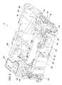
- grass mowing machine operator platform 114 may include a one-piece plastic composite molded structure that may be mounted to the grass mowing machine frame.
- the one-piece plastic composite molded structure may be positioned between the longitudinal frame members, adjacent or between the front and rear cross members.
- the one-piece plastic composite molded structure may be fastened to and supported by the longitudinal frame members and cross members.
- the one-piece plastic composite molded structure may be fastened to the frame at six attachment points using shoulder bolts 116 through mounting holes 118 near the perimeter of the operator platform.
- the one-piece plastic composite molded structure may also be covered by plastic shroud 120 over the top and side surfaces of the structure, and the plastic shroud may be secured to the operator platform with rivets or other fasteners.
- the one-piece plastic composite molded structure may be blow molded using high pressure structural foam, most preferably 30% glass filled polypropylene with a blowing agent.
- the structure may be molded from a variety of different plastic materials having high strength and rigidity.
- the material may be in the range of about 15% to about 50% glass filled polypropylene, polyamide or polyethylene.
- the one-piece plastic composite molded structure may have walls with a wall thickness between about 5 mm and about 7 mm.
- the one-piece plastic composite molded structure may form a ribbed support structure having a plurality of interior pockets and compartments. The pockets or compartments in may isolate components such as a battery, fuse and relay block from heat, moisture, dirt or other contaminants.
- one-piece plastic composite molded structure of grass mowing machine operator platform 114 may provide the sole or only support structure for operator seat 122 and one or more operating systems of the grass mowing machine including steering system 124, brake system 126, fuel system 128 and deck lift system 130.
- One or more of the systems may be mounted to the grass mowing machine operator platform before the structure is installed on the grass mowing machine.
- the operator platform may include the operator seat, steering system, brake system, fuel system and deck lift system..
- the one-piece plastic composite molded structure may include seat hinge supports 132 on top of front wall 134 of the operator platform.
- the seat hinge supports on the front wall of the one-piece plastic composite molded structure may provide a horizontal pivot axis for the operator seat to pivot or tip rearwardly to a normal use position, and forwardly to a non-use position.
- a pair of seat hinge pins 136 may be inserted through the seat hinge supports and a lower front portion of the operator seat.
- the one-piece plastic composite molded structure may include seat spring supports 138 which may be sheet metal members attached to the top of back wall 140 of the operator platform, and may provide a contact surface for coil springs 142 under the operator seat.
- the seat spring supports also may be secured to the rear cross member of the frame using threaded fasteners to help retain the operator platform to the frame. The coil springs may rest on the seat spring supports while the seat is in the normal or use position.
- the one-piece plastic composite molded structure may include L-shaped or T-shaped steering lever slots 146 molded into a top of the structure for mounting the steering system of a zero turn riding mower.
- the steering lever slots may have double walls 148 and reinforcing ribs 150 to enhance their rigidity.
- Steering pivot bolts 152 may be attached and secured to integral bearing surfaces 154 through the double walls of the steering lever slots. With integral bearing surfaces molded into the one-piece plastic composite molded structure, bushings are not required.
- Dual steering levers 156 may be attached to pivot members 158 inserted through the steering lever slots and pivotably attached to the steering pivot bolts.
- the steering lever slots in the one-piece plastic composite molded structure may provide stops for the dual steering levers, to pivot in forward or reverse as the steering levers are used to turn the traction wheels and steer the machine, and to the left and right as the steering levers are pivoted to park the zero turn riding mower and enter or exit the operator seat.
- the steering lever slots may include sloped internal surfaces that provide stops for each of the dual steering levers in the parked position.
- the plastic shroud may have openings 160 for the steering lever slots.
- the steering lever slots also may include recessed nut pocket surfaces for the threaded fasteners, to help move the load path away from notches in the slots. Now referring to Fig.
- the one-piece plastic composite molded structure of the grass mowing machine operator platform also may include channels 166 in the bottom surface to locate and provide access to shock absorbers 168 for the dual lever steering levers.
- a first end of each shock absorber may be attached to the steering pivot bolt, and a second end may be attached to L-shaped pin 170 inserted through notch 172 in the operator platform.
- the one-piece plastic composite molded structure of the grass mowing machine operator platform may include brake lever slots 174 and brake handle opening 176 in the front side wall of the operator platform for mounting the brake system.
- Each brake lever slot may have an integral bearing surface of at least about 1 cm in length along the axis of brake lever 178. Because of the integral bearing surfaces, bushings are not required.
- Brake lever retainer 180 may be attached and secured to the front wall of the one-piece plastic composite molded structure to capture and retain the brake lever on integral bearing surfaces of the brake lever slots.
- the brake lever may be a one piece rod or wire form having a first or handle end 182 that may extend through the brake handle opening.
- the plastic shroud also may have opening 184 for the brake lever handle.
- an operator may lift the handle to pivot the brake lever between top and bottom stops provided by the opening in the front wall.
- An offset or U-shaped portion 186 of the brake lever may be attached to brake cable 188.
- Lifting or lowering the handle may pivot the brake lever between the stops, retracting or releasing the brake cable.
- Brake cable conduit 190 may be fastened to brake cable conduit support bracket 192 secured to internal wall 194 of the one-piece plastic composite molded structure.
- the brake cable conduit housing the brake cable may be routed through the structure to the rear of the operator platform, where the brake cable may branch to a pair of cables attached to brake pawls or calipers (not shown) that may apply braking pressure to the rear traction drive wheels.
- the grass mowing machine operator platform may include fuel tank compartment 196 for mounting fuel tank 198.
- the fuel tank compartment may provide protective walls 199 around the fuel tank.
- Fuel tank cap 200 on the filler neck of the fuel tank may be accessed through an opening in the plastic shroud.
- the underside of the operator platform may include pocket or recess 204 for mounting carbon canister 206 connected to the fuel tank by vapor hoses 210.
- the one-piece plastic composite molded structure may include deck lift shaft supports 212 adjacent one side of the operator platform for mounting the deck lift system.
- the deck lift shaft supports may have integral bearing surfaces of at least about 1 cm in length along the axis of deck lift shaft 214.
- Shaft retainer 216 may help hold the deck lift shaft in place on the deck lift shaft supports.
- Deck lift lever 218 may be attached to the outer end of the deck lift shaft.
- the deck lift lever may include deck lift handle 220 that may rest on pin 222 inserted through one of holes 224 for an operator-selected height of cut on height of cut sector 226 attached to the longitudinal frame member.
- the upper end of deck lift crank 228 may be attached to the inner end of the deck lift crank.
- the deck lift crank may extend from the deck lift shaft down through an opening in the operator platform, where the lower end of the deck lift crank may be attached to deck lift cables 232. Lifting or lowering the deck lift handle may pivot the deck lift shaft and deck lift crank, retracting or releasing the deck lift cables.
- a first end of deck lift cable conduits 234 may be fastened to deck lift cable conduit support bracket 236 which may be secured to slot 238 in the outer wall of the operator platform.
- the deck lift cable conduits housing the deck lift cables may be routed through the operator platform and a second end of the conduits may be fastened to weldments 240 on the longitudinal frame members.
- the deck lift cables may be attached to left and right deck lift arms 242 that are pivotably attached to raise and lower mower deck 244.
- the one-piece plastic composite molded structure may include compartment 246 that may be accessed from the top of the operator platform under or adjacent the operator seat.
- the shroud may provide hinged or removable access panels 250 over the top of the compartment.
- Compartment 246 may house battery 254, and a fuse and relay block, and/or other electrical components that may need service or replacement.
- T-shaped ribs on the compartment wall may engage mating slots in the side panel of the fuse and relay block.
- the grass mowing machine operator platform may include one or more compartments under the seat that may provide storage space for various items.
Landscapes
- Life Sciences & Earth Sciences (AREA)
- Environmental Sciences (AREA)
- Harvester Elements (AREA)
Abstract
Description
- The present invention relates to grass mowing machines, and specifically to a grass mowing machine operator platform.
- Grass mowing machines typically include a frame that supports the machine's components including an internal combustion engine, battery pack or other power source, axles, wheels, steering and brake systems and an operator seat. The operator seat may be mounted between the front and rear axles, either to the middle or toward the rear of the frame. The engine, battery pack or other power source may be mounted to the frame forwardly of the operator seat, or in the case of a zero turn riding mower, behind the operator seat at the rear of the frame. Steering and brake controls may be located mid frame where an operator may access them from the operator seat. For example, zero turn riding mowers may have dual lever steering levers mounted to the frame on the left and right of the operator seat that an operator can pivot fore and aft, and also side-to-side, to control a pair of rear wheel motors. Brake systems on grass mowing machines may be actuated using a pedal and/or lever that may be mounted to the mid frame forwardly of the operator seat and/or beside the seat. A fuel tank may be mounted adjacent or behind the operator seat. Deck or implement lift systems may be mounted to the mid frame of the machine so that an operator may use a pedal and/or lever to raise and lower the deck or other implement. Additionally, engine and electrical controls and gauges may be mounted to a control panel in front of or next to the operator seat.
- Mounting these components onto the mid frame of a grass mowing machine can be complex and difficult. For example, mounting brackets, fasteners and other attachment devices may be used to attach and hold the components to the frame. The number of mounting brackets, fasteners and other attachment devices increases the complexity of grass mowing machines, adds to the parts count and cost, and contributes significant time to the assembly process. These parts also may reduce a machine's reliability and performance. A grass mowing machine operator platform is needed that can reduce complexity, reduce the parts count and cost, reduce assembly time, and increase reliability and performance.
- A grass mowing machine operator platform having a one-piece plastic composite molded structure mounted on a grass mowing machine frame. The one-piece plastic composite molded structure may include hinge supports molded into a top front wall that pivotably support an operator seat, steering lever slots molded into a top surface and having integral bearing surfaces pivotably supporting a pair of steering levers, and brake lever slots molded into a side wall and having integral bearing surfaces pivotably supporting a brake lever.
-
Fig. 1 is and exploded perspective view of a grass mowing machine with an operator platform according to one embodiment of the invention. -
Fig. 2 is a top perspective view of a grass mowing machine operator platform according to one embodiment of the invention. -
Fig. 3 is a top perspective view of a grass mowing machine operator platform with a steering system according to one embodiment of the invention. - Fig. 3A is bottom view of a portion of the grass mowing machine operator platform with a steering system according to one embodiment of the invention.
-
Fig. 4 is a front perspective view a portion of a grass mowing machine operator platform with a brake system according to one embodiment of the invention. -
Fig. 5 is a top perspective view of a grass mowing machine operator platform with a fuel system according to one embodiment of the invention. -
Fig. 5B is a bottom perspective view of a grass mowing machine operator platform with fuel system according to one embodiment of the invention. -
Fig. 6 is a side perspective view of a portion of a grass mowing machine with a deck lift system according to one embodiment of the invention. - As shown in
Fig. 1 , in one embodiment,grass mowing machine 100 may be a zero turn riding mower having a pair oflongitudinal frame members 102 supported by a pair offront caster wheels 104 at or near the front end of the longitudinal frame members, and a pair of reartraction drive wheels 106 at or near the rear end of the longitudinal frame members. The grass mowing machine frame also may include front and rear cross members orplates Internal combustion engine 112 may be mounted to the frame rearwardly of the rear cross member or onto a rear plate. Alternatively, a battery pack or other power source may be mounted on or to the rear of the frame, instead of an internal combustion engine. In other embodiments, the grass mowing machine may be a lawn tractor having an internal combustion engine, battery pack or other power source mounted forwardly of one or both cross members. - As shown in
Fig. 2 , in one embodiment, grass mowingmachine operator platform 114 may include a one-piece plastic composite molded structure that may be mounted to the grass mowing machine frame. The one-piece plastic composite molded structure may be positioned between the longitudinal frame members, adjacent or between the front and rear cross members. The one-piece plastic composite molded structure may be fastened to and supported by the longitudinal frame members and cross members. For example, the one-piece plastic composite molded structure may be fastened to the frame at six attachment points usingshoulder bolts 116 throughmounting holes 118 near the perimeter of the operator platform. The one-piece plastic composite molded structure may also be covered byplastic shroud 120 over the top and side surfaces of the structure, and the plastic shroud may be secured to the operator platform with rivets or other fasteners. - In one embodiment, the one-piece plastic composite molded structure may be blow molded using high pressure structural foam, most preferably 30% glass filled polypropylene with a blowing agent. The structure may be molded from a variety of different plastic materials having high strength and rigidity. For example, the material may be in the range of about 15% to about 50% glass filled polypropylene, polyamide or polyethylene. The one-piece plastic composite molded structure may have walls with a wall thickness between about 5 mm and about 7 mm. The one-piece plastic composite molded structure may form a ribbed support structure having a plurality of interior pockets and compartments. The pockets or compartments in may isolate components such as a battery, fuse and relay block from heat, moisture, dirt or other contaminants.
- In one embodiment, one-piece plastic composite molded structure of grass mowing
machine operator platform 114 may provide the sole or only support structure foroperator seat 122 and one or more operating systems of the grass mowing machine includingsteering system 124,brake system 126,fuel system 128 anddeck lift system 130. One or more of the systems may be mounted to the grass mowing machine operator platform before the structure is installed on the grass mowing machine. As assembled, the operator platform may include the operator seat, steering system, brake system, fuel system and deck lift system.. - In one embodiment shown in
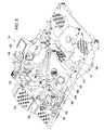
Fig. 3 , the one-piece plastic composite molded structure may include seat hinge supports 132 on top offront wall 134 of the operator platform. The seat hinge supports on the front wall of the one-piece plastic composite molded structure may provide a horizontal pivot axis for the operator seat to pivot or tip rearwardly to a normal use position, and forwardly to a non-use position. A pair ofseat hinge pins 136 may be inserted through the seat hinge supports and a lower front portion of the operator seat. Additionally, the one-piece plastic composite molded structure may includeseat spring supports 138 which may be sheet metal members attached to the top ofback wall 140 of the operator platform, and may provide a contact surface forcoil springs 142 under the operator seat. The seat spring supports also may be secured to the rear cross member of the frame using threaded fasteners to help retain the operator platform to the frame. The coil springs may rest on the seat spring supports while the seat is in the normal or use position. - In one embodiment shown in
Fig. 3 , the one-piece plastic composite molded structure may include L-shaped or T-shapedsteering lever slots 146 molded into a top of the structure for mounting the steering system of a zero turn riding mower. The steering lever slots may havedouble walls 148 and reinforcingribs 150 to enhance their rigidity.Steering pivot bolts 152 may be attached and secured to integral bearingsurfaces 154 through the double walls of the steering lever slots. With integral bearing surfaces molded into the one-piece plastic composite molded structure, bushings are not required.Dual steering levers 156 may be attached topivot members 158 inserted through the steering lever slots and pivotably attached to the steering pivot bolts. The steering lever slots in the one-piece plastic composite molded structure may provide stops for the dual steering levers, to pivot in forward or reverse as the steering levers are used to turn the traction wheels and steer the machine, and to the left and right as the steering levers are pivoted to park the zero turn riding mower and enter or exit the operator seat. The steering lever slots may include sloped internal surfaces that provide stops for each of the dual steering levers in the parked position. The plastic shroud may have openings 160 for the steering lever slots. The steering lever slots also may include recessed nut pocket surfaces for the threaded fasteners, to help move the load path away from notches in the slots. Now referring toFig. 3B , the one-piece plastic composite molded structure of the grass mowing machine operator platform also may includechannels 166 in the bottom surface to locate and provide access toshock absorbers 168 for the dual lever steering levers. A first end of each shock absorber may be attached to the steering pivot bolt, and a second end may be attached to L-shaped pin 170 inserted throughnotch 172 in the operator platform. - In one embodiment shown in
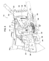
Fig. 4 , the one-piece plastic composite molded structure of the grass mowing machine operator platform may includebrake lever slots 174 and brake handle opening 176 in the front side wall of the operator platform for mounting the brake system. Each brake lever slot may have an integral bearing surface of at least about 1 cm in length along the axis ofbrake lever 178. Because of the integral bearing surfaces, bushings are not required.Brake lever retainer 180 may be attached and secured to the front wall of the one-piece plastic composite molded structure to capture and retain the brake lever on integral bearing surfaces of the brake lever slots. The brake lever may be a one piece rod or wire form having a first or handleend 182 that may extend through the brake handle opening. The plastic shroud also may have opening 184 for the brake lever handle. To apply the brake, an operator may lift the handle to pivot the brake lever between top and bottom stops provided by the opening in the front wall. An offset orU-shaped portion 186 of the brake lever may be attached tobrake cable 188. Lifting or lowering the handle may pivot the brake lever between the stops, retracting or releasing the brake cable.Brake cable conduit 190 may be fastened to brake cableconduit support bracket 192 secured tointernal wall 194 of the one-piece plastic composite molded structure. The brake cable conduit housing the brake cable may be routed through the structure to the rear of the operator platform, where the brake cable may branch to a pair of cables attached to brake pawls or calipers (not shown) that may apply braking pressure to the rear traction drive wheels. - In one embodiment shown in
Fig. 5 , the grass mowing machine operator platform may includefuel tank compartment 196 for mountingfuel tank 198. The fuel tank compartment may provideprotective walls 199 around the fuel tank.Fuel tank cap 200 on the filler neck of the fuel tank may be accessed through an opening in the plastic shroud. Now referring toFig. 5B , the underside of the operator platform may include pocket orrecess 204 for mountingcarbon canister 206 connected to the fuel tank byvapor hoses 210. - In one embodiment, shown in
Fig. 6 , the one-piece plastic composite molded structure may include deck lift shaft supports 212 adjacent one side of the operator platform for mounting the deck lift system. The deck lift shaft supports may have integral bearing surfaces of at least about 1 cm in length along the axis ofdeck lift shaft 214.Shaft retainer 216 may help hold the deck lift shaft in place on the deck lift shaft supports.Deck lift lever 218 may be attached to the outer end of the deck lift shaft. The deck lift lever may include deck lift handle 220 that may rest onpin 222 inserted through one ofholes 224 for an operator-selected height of cut on height ofcut sector 226 attached to the longitudinal frame member. The upper end of deck lift crank 228 may be attached to the inner end of the deck lift crank. The deck lift crank may extend from the deck lift shaft down through an opening in the operator platform, where the lower end of the deck lift crank may be attached todeck lift cables 232. Lifting or lowering the deck lift handle may pivot the deck lift shaft and deck lift crank, retracting or releasing the deck lift cables. A first end of deck lift cable conduits 234 may be fastened to deck lift cableconduit support bracket 236 which may be secured to slot 238 in the outer wall of the operator platform. The deck lift cable conduits housing the deck lift cables may be routed through the operator platform and a second end of the conduits may be fastened to weldments 240 on the longitudinal frame members. The deck lift cables may be attached to left and right deck liftarms 242 that are pivotably attached to raise and lower mower deck 244. - In one embodiment, as shown in
Fig. 2 , the one-piece plastic composite molded structure may includecompartment 246 that may be accessed from the top of the operator platform under or adjacent the operator seat. The shroud may provide hinged orremovable access panels 250 over the top of the compartment.Compartment 246 may housebattery 254, and a fuse and relay block, and/or other electrical components that may need service or replacement. To retain the fuse and relay block in the compartment without requiring hardware or tools, T-shaped ribs on the compartment wall may engage mating slots in the side panel of the fuse and relay block. Additionally, the grass mowing machine operator platform may include one or more compartments under the seat that may provide storage space for various items.
Claims (6)
- A grass mowing machine operator platform comprising:a one-piece plastic composite molded structure mounted on a grass mowing machine frame including:hinge supports molded into a top front wall of the one-piece plastic composite molded structure pivotably supporting an operator seat;steering lever slots molded into a top surface of the one-piece plastic composite molded structure and having integral bearing surfaces pivotably supporting a pair of steering levers; andbrake lever slots molded into a side wall of the one-piece plastic composite molded structure and having integral bearing surfaces pivotably supporting a brake lever.
- The grass mowing machine operator platform according to claim 1, further comprising at least storage compartment molded into the one-piece plastic composite molded structure.
- The grass mowing machine operator platform according to claim 1 or 2, wherein the one-piece plastic composite molded structure further comprises integral bearing surfaces pivotably supporting a deck lift shaft of a deck lift system.
- The grass mowing machine operator platform according to one of the claims 1 to 3, wherein the one-piece plastic composite molded structure further comprises a fuel tank compartment.
- A grass mowing machine operator platform according to one of the claims 1 to 4, further comprising a plastic shroud over the one-piece plastic composite molded structure.
- A grass mowing machine operator platform according to one of the claims 1 to 5, wherein the one-piece plastic composite molded structure is the only support of the pair of steering levers.
Applications Claiming Priority (1)
| Application Number | Priority Date | Filing Date | Title |
|---|---|---|---|
| US13/653,959 US9510503B2 (en) | 2012-10-17 | 2012-10-17 | Grass mowing machine operator platform |
Publications (2)
| Publication Number | Publication Date |
|---|---|
| EP2721916A1 true EP2721916A1 (en) | 2014-04-23 |
| EP2721916B1 EP2721916B1 (en) | 2015-12-30 |
Family
ID=49322211
Family Applications (1)
| Application Number | Title | Priority Date | Filing Date |
|---|---|---|---|
| EP13187084.2A Active EP2721916B1 (en) | 2012-10-17 | 2013-10-02 | Grass mowing machine operator platform |
Country Status (3)
| Country | Link |
|---|---|
| US (1) | US9510503B2 (en) |
| EP (1) | EP2721916B1 (en) |
| CN (1) | CN103766034B (en) |
Cited By (2)
| Publication number | Priority date | Publication date | Assignee | Title |
|---|---|---|---|---|
| WO2015169381A1 (en) * | 2014-05-08 | 2015-11-12 | Husqvarna Ab | Lawn care vehicle brake system |
| EP3111740A1 (en) | 2015-06-29 | 2017-01-04 | GGP Italy S.p.A. | Frame of a lawnmower vehicle |
Families Citing this family (13)
| Publication number | Priority date | Publication date | Assignee | Title |
|---|---|---|---|---|
| CN104663110A (en) * | 2014-12-03 | 2015-06-03 | 宁波大叶园林设备有限公司 | Lawn mower with engine with LPG (liquid propane gas) fuel tank unit and production method of LPG fuel tank unit |
| US11089726B2 (en) * | 2018-03-26 | 2021-08-17 | Honda Motor Co., Ltd. | Lawnmower mulch plug fixing method |
| US11357170B1 (en) * | 2018-08-24 | 2022-06-14 | Excel Industries, Inc. | Steering lever pivot assembly for terrain working vehicle |
| US11091200B2 (en) * | 2019-02-21 | 2021-08-17 | Deere & Company | Zero turning radius mower steering lever modules |
| US11032973B2 (en) * | 2019-07-26 | 2021-06-15 | Generac Power Systems, Inc. | Battery-operated electric mower |
| US12296694B2 (en) | 2021-03-10 | 2025-05-13 | Techtronic Cordless Gp | Lawnmowers |
| CA3158652A1 (en) | 2021-05-14 | 2022-11-14 | Techtronic Cordless Gp | Removable seat and lawnmowers with removable seats |
| USD1014568S1 (en) | 2022-02-14 | 2024-02-13 | Techtronic Cordless Gp | Lawn mower |
| USD1015381S1 (en) | 2022-02-14 | 2024-02-20 | Techtronic Cordless Gp | Lawn mower |
| US12409821B2 (en) | 2022-11-23 | 2025-09-09 | Deere & Company | Zero turning radius mower park brake system |
| US12466481B2 (en) | 2022-12-21 | 2025-11-11 | Deere & Company | Control lever calibration system |
| US20240270310A1 (en) | 2023-02-14 | 2024-08-15 | Deere & Company | Zero turning radius mower steering sensor linkage |
| US12477976B1 (en) | 2023-06-06 | 2025-11-25 | Deere & Company | Steering arm return to neutral mechanism |
Citations (4)
| Publication number | Priority date | Publication date | Assignee | Title |
|---|---|---|---|---|
| EP0523850A2 (en) * | 1991-06-14 | 1993-01-20 | The Dow Chemical Company | Vehicle structure |
| US5238267A (en) * | 1991-06-14 | 1993-08-24 | Deere & Company | Vehicle structure |
| US5558368A (en) * | 1994-11-03 | 1996-09-24 | Deere & Company | Chassis structure |
| US20090217636A1 (en) * | 2008-01-22 | 2009-09-03 | Exmark Manufacturing Company | Control system having return-to-neutral biasing mechanism and vehicle incorporating same |
Family Cites Families (39)
| Publication number | Priority date | Publication date | Assignee | Title |
|---|---|---|---|---|
| US3093948A (en) * | 1961-09-11 | 1963-06-18 | Root Mfg Company Inc | Rotating disk mower with vertically adjustable rotating blade |
| US3934392A (en) * | 1974-11-04 | 1976-01-27 | International Harvester Company | Debris collector for lawn and garden machines |
| US4738328A (en) * | 1987-01-06 | 1988-04-19 | Bryant-Poff, Inc. | Housing for a riding lawnmower transmission |
| US4924665A (en) * | 1988-12-19 | 1990-05-15 | Crosley Gilbert O | Lawn mower blade assembly |
| US5042239A (en) * | 1990-04-06 | 1991-08-27 | Scag Power Equipment, Inc. | Power transmission and steering apparatus for vehicles |
| US5398489A (en) * | 1991-11-08 | 1995-03-21 | Kubota Corporation | Lawn mower with vertical adjustment |
| US5787693A (en) * | 1994-10-28 | 1998-08-04 | Black & Decker Inc. | Universal, retrofittable powerhead for small gasoline engine power implements |
| US5507138A (en) * | 1994-12-16 | 1996-04-16 | Wright Manufacturing Inc. | Power mower with riding platform for supporting standing-operator |
| US5809755A (en) * | 1994-12-16 | 1998-09-22 | Wright Manufacturing, Inc. | Power mower with riding platform for supporting standing operator |
| US5638668A (en) * | 1995-06-26 | 1997-06-17 | The Toro Company | Lawn mower having nested deck and liner |
| US5727372A (en) * | 1996-05-30 | 1998-03-17 | The Toro Company | On-board charging system for electric lawn mower |
| JP3685680B2 (en) * | 2000-03-30 | 2005-08-24 | 株式会社クボタ | Lawn mower |
| US6497453B2 (en) | 2000-08-10 | 2002-12-24 | Murray, Inc. | Frame and seat support for a riding lawn mower |
| JP3894757B2 (en) * | 2001-09-07 | 2007-03-22 | 株式会社クボタ | Riding mower |
| US6729115B2 (en) * | 2002-04-13 | 2004-05-04 | Excel Industries, Inc. | Mower with combined steering an brake levers |
| WO2004057632A2 (en) * | 2002-12-19 | 2004-07-08 | Mtd Products Inc | Mechanism for discontinuing power to an implement drive during machine reverse travel (no power in reverse) with automatic reengagement |
| SE525364C2 (en) * | 2003-06-10 | 2005-02-08 | Ingemansson Tech Ab | Lawn mower with vibration damping |
| US7451865B2 (en) * | 2005-01-18 | 2008-11-18 | Commercial Turf Products, Ltd. | Park brake and control lever interlock for ZTR vehicle |
| US7299610B2 (en) * | 2005-02-10 | 2007-11-27 | Great Plains Manufacturing, Incorporated | Park/drive mechanical interlock system for zero turn radius mowers |
| US20060228943A1 (en) * | 2005-04-12 | 2006-10-12 | Custom-Pak, Inc. | Retractable undercut core pull |
| US20060277884A1 (en) * | 2005-06-10 | 2006-12-14 | Ariens Company | Object detection system for a lawn mower |
| US7318311B2 (en) * | 2005-08-22 | 2008-01-15 | Wright Manufacturing, Inc. | Lawn mower with deck lift system and/or pump lock-out system |
| US7882914B2 (en) | 2006-01-19 | 2011-02-08 | Husqvarna Professional Outdoor Products Inc. | Operator platform isolation system |
| JP4814687B2 (en) * | 2006-01-26 | 2011-11-16 | 株式会社クボタ | Riding mower |
| US7458432B2 (en) * | 2006-06-16 | 2008-12-02 | Deere & Company | Dual lever steering control mechanism |
| US7712294B2 (en) * | 2006-08-11 | 2010-05-11 | Wright Manufacturing, Inc. | Lawn mower with deck lift system including automatic latch resetting |
| US20120159916A1 (en) * | 2007-01-15 | 2012-06-28 | Kanzaki Kokyukoki Manufacturing Co., Ltd. | Control sysytem for motor-driven lawnmower vehicle |
| US7686108B2 (en) * | 2007-02-09 | 2010-03-30 | Great Plains Manufacturing, Inc. | Electrically released parking brake for zero turn radius mower |
| US20090064650A1 (en) * | 2007-03-29 | 2009-03-12 | Eberle J Robert | Cutting deck, front axle and steering controls for a lawn mower |
| CN201094200Y (en) * | 2007-05-31 | 2008-08-06 | 林正道 | Mower bottom board walking device |
| US8235151B2 (en) * | 2007-08-14 | 2012-08-07 | Deere & Company | Return to neutral control mechanism for zero turning radius mower |
| US8087481B2 (en) * | 2007-08-29 | 2012-01-03 | Deere & Company | Dual lever steering controls with control stops |
| US8245806B2 (en) * | 2008-12-20 | 2012-08-21 | Nick Newell | Riding mower with a suspension component coupled to a plurality of user support components and methods of making and using thereof |
| US8539869B2 (en) * | 2009-02-03 | 2013-09-24 | Brady Worldwide, Inc. | Guillotine cutter |
| US8381885B2 (en) * | 2009-12-14 | 2013-02-26 | Kohler Co. | Brake system and lawn mower implementing the same |
| US8186475B2 (en) | 2010-05-12 | 2012-05-29 | Metalcraft Of Mayville, Inc. | Suspended operator platform |
| US7950211B1 (en) * | 2010-08-12 | 2011-05-31 | Scott Ta | Power tool for facilitating an operator's alternative cutting of foliage over the ground and along the ground |
| US8522901B1 (en) * | 2012-09-04 | 2013-09-03 | Timothy A. VanLue | Dual steering system for zero turning radius mower |
| CN203399528U (en) * | 2013-07-23 | 2014-01-22 | 重庆润通动力制造有限公司 | Frame of striding type lawn mower |
-
2012
- 2012-10-17 US US13/653,959 patent/US9510503B2/en active Active
-
2013
- 2013-10-02 EP EP13187084.2A patent/EP2721916B1/en active Active
- 2013-10-15 CN CN201310481788.8A patent/CN103766034B/en active Active
Patent Citations (4)
| Publication number | Priority date | Publication date | Assignee | Title |
|---|---|---|---|---|
| EP0523850A2 (en) * | 1991-06-14 | 1993-01-20 | The Dow Chemical Company | Vehicle structure |
| US5238267A (en) * | 1991-06-14 | 1993-08-24 | Deere & Company | Vehicle structure |
| US5558368A (en) * | 1994-11-03 | 1996-09-24 | Deere & Company | Chassis structure |
| US20090217636A1 (en) * | 2008-01-22 | 2009-09-03 | Exmark Manufacturing Company | Control system having return-to-neutral biasing mechanism and vehicle incorporating same |
Cited By (4)
| Publication number | Priority date | Publication date | Assignee | Title |
|---|---|---|---|---|
| WO2015169381A1 (en) * | 2014-05-08 | 2015-11-12 | Husqvarna Ab | Lawn care vehicle brake system |
| AU2014393640B2 (en) * | 2014-05-08 | 2018-05-17 | Husqvarna Ab | Lawn care vehicle brake system |
| US10045485B2 (en) | 2014-05-08 | 2018-08-14 | Husqvarna Ab | Lawn care vehicle brake system |
| EP3111740A1 (en) | 2015-06-29 | 2017-01-04 | GGP Italy S.p.A. | Frame of a lawnmower vehicle |
Also Published As
| Publication number | Publication date |
|---|---|
| CN103766034A (en) | 2014-05-07 |
| US20140103629A1 (en) | 2014-04-17 |
| US9510503B2 (en) | 2016-12-06 |
| CN103766034B (en) | 2018-01-09 |
| EP2721916B1 (en) | 2015-12-30 |
Similar Documents
| Publication | Publication Date | Title |
|---|---|---|
| EP2721916B1 (en) | Grass mowing machine operator platform | |
| US8944449B2 (en) | Side-by-side vehicle | |
| US9296426B2 (en) | Chassis of a motor vehicle including a means for absorbing a frontal impact | |
| US8047557B2 (en) | Vehicle body frame structure | |
| EP3439453B1 (en) | Stand-on lawn care vehicle | |
| US3667563A (en) | Supporting structure for platform defining fuel and battery compartment | |
| KR101647926B1 (en) | Work vehicle | |
| EP3189997B1 (en) | Work vehicle having engine mounted thereto | |
| CA1263342A (en) | Method and means for lift truck assembly and service | |
| JP2018197076A (en) | Electric work vehicle | |
| US9180776B2 (en) | Work vehicle with engine mounted rearwardly | |
| US11091200B2 (en) | Zero turning radius mower steering lever modules | |
| US20170341685A1 (en) | Turf maintenance vehicle and support platform isolator system for same | |
| US3438672A (en) | Isolated platform mounting | |
| JP6842949B2 (en) | combine | |
| JP4392836B2 (en) | Wheel loader | |
| CN116114460A (en) | Riding type mowing equipment | |
| JP2012017098A (en) | Working vehicle | |
| JP7794186B2 (en) | Work vehicles | |
| EP4368430A1 (en) | Work vehicle | |
| JP2019047746A (en) | Sulky lawn mower | |
| JP4618402B2 (en) | Traveling body | |
| JP7104674B2 (en) | Rolling machine | |
| JP7115435B2 (en) | riding lawn mower | |
| JP2019047747A (en) | Riding lawn mower |
Legal Events
| Date | Code | Title | Description |
|---|---|---|---|
| PUAI | Public reference made under article 153(3) epc to a published international application that has entered the european phase |
Free format text: ORIGINAL CODE: 0009012 |
|
| AK | Designated contracting states |
Kind code of ref document: A1 Designated state(s): AL AT BE BG CH CY CZ DE DK EE ES FI FR GB GR HR HU IE IS IT LI LT LU LV MC MK MT NL NO PL PT RO RS SE SI SK SM TR |
|
| AX | Request for extension of the european patent |
Extension state: BA ME |
|
| 17P | Request for examination filed |
Effective date: 20141023 |
|
| RBV | Designated contracting states (corrected) |
Designated state(s): AL AT BE BG CH CY CZ DE DK EE ES FI FR GB GR HR HU IE IS IT LI LT LU LV MC MK MT NL NO PL PT RO RS SE SI SK SM TR |
|
| GRAP | Despatch of communication of intention to grant a patent |
Free format text: ORIGINAL CODE: EPIDOSNIGR1 |
|
| RIC1 | Information provided on ipc code assigned before grant |
Ipc: A01D 34/81 20060101AFI20150415BHEP Ipc: A01D 34/00 20060101ALI20150415BHEP |
|
| INTG | Intention to grant announced |
Effective date: 20150519 |
|
| GRAS | Grant fee paid |
Free format text: ORIGINAL CODE: EPIDOSNIGR3 |
|
| RIN1 | Information on inventor provided before grant (corrected) |
Inventor name: ELHARDT, PAUL Inventor name: RESSLER, KYLET Inventor name: GENZ, THOMAS R |
|
| GRAA | (expected) grant |
Free format text: ORIGINAL CODE: 0009210 |
|
| AK | Designated contracting states |
Kind code of ref document: B1 Designated state(s): AL AT BE BG CH CY CZ DE DK EE ES FI FR GB GR HR HU IE IS IT LI LT LU LV MC MK MT NL NO PL PT RO RS SE SI SK SM TR |
|
| REG | Reference to a national code |
Ref country code: GB Ref legal event code: FG4D |
|
| REG | Reference to a national code |
Ref country code: CH Ref legal event code: EP |
|
| REG | Reference to a national code |
Ref country code: AT Ref legal event code: REF Ref document number: 767026 Country of ref document: AT Kind code of ref document: T Effective date: 20160115 |
|
| REG | Reference to a national code |
Ref country code: IE Ref legal event code: FG4D |
|
| REG | Reference to a national code |
Ref country code: DE Ref legal event code: R096 Ref document number: 602013004329 Country of ref document: DE |
|
| REG | Reference to a national code |
Ref country code: LT Ref legal event code: MG4D |
|
| PG25 | Lapsed in a contracting state [announced via postgrant information from national office to epo] |
Ref country code: HR Free format text: LAPSE BECAUSE OF FAILURE TO SUBMIT A TRANSLATION OF THE DESCRIPTION OR TO PAY THE FEE WITHIN THE PRESCRIBED TIME-LIMIT Effective date: 20151230 Ref country code: NO Free format text: LAPSE BECAUSE OF FAILURE TO SUBMIT A TRANSLATION OF THE DESCRIPTION OR TO PAY THE FEE WITHIN THE PRESCRIBED TIME-LIMIT Effective date: 20160330 Ref country code: LT Free format text: LAPSE BECAUSE OF FAILURE TO SUBMIT A TRANSLATION OF THE DESCRIPTION OR TO PAY THE FEE WITHIN THE PRESCRIBED TIME-LIMIT Effective date: 20151230 |
|
| REG | Reference to a national code |
Ref country code: NL Ref legal event code: MP Effective date: 20151230 |
|
| REG | Reference to a national code |
Ref country code: AT Ref legal event code: MK05 Ref document number: 767026 Country of ref document: AT Kind code of ref document: T Effective date: 20151230 |
|
| PG25 | Lapsed in a contracting state [announced via postgrant information from national office to epo] |
Ref country code: FI Free format text: LAPSE BECAUSE OF FAILURE TO SUBMIT A TRANSLATION OF THE DESCRIPTION OR TO PAY THE FEE WITHIN THE PRESCRIBED TIME-LIMIT Effective date: 20151230 Ref country code: RS Free format text: LAPSE BECAUSE OF FAILURE TO SUBMIT A TRANSLATION OF THE DESCRIPTION OR TO PAY THE FEE WITHIN THE PRESCRIBED TIME-LIMIT Effective date: 20151230 Ref country code: LV Free format text: LAPSE BECAUSE OF FAILURE TO SUBMIT A TRANSLATION OF THE DESCRIPTION OR TO PAY THE FEE WITHIN THE PRESCRIBED TIME-LIMIT Effective date: 20151230 Ref country code: GR Free format text: LAPSE BECAUSE OF FAILURE TO SUBMIT A TRANSLATION OF THE DESCRIPTION OR TO PAY THE FEE WITHIN THE PRESCRIBED TIME-LIMIT Effective date: 20160331 Ref country code: SE Free format text: LAPSE BECAUSE OF FAILURE TO SUBMIT A TRANSLATION OF THE DESCRIPTION OR TO PAY THE FEE WITHIN THE PRESCRIBED TIME-LIMIT Effective date: 20151230 |
|
| PG25 | Lapsed in a contracting state [announced via postgrant information from national office to epo] |
Ref country code: NL Free format text: LAPSE BECAUSE OF FAILURE TO SUBMIT A TRANSLATION OF THE DESCRIPTION OR TO PAY THE FEE WITHIN THE PRESCRIBED TIME-LIMIT Effective date: 20151230 |
|
| PG25 | Lapsed in a contracting state [announced via postgrant information from national office to epo] |
Ref country code: ES Free format text: LAPSE BECAUSE OF FAILURE TO SUBMIT A TRANSLATION OF THE DESCRIPTION OR TO PAY THE FEE WITHIN THE PRESCRIBED TIME-LIMIT Effective date: 20151230 Ref country code: IT Free format text: LAPSE BECAUSE OF FAILURE TO SUBMIT A TRANSLATION OF THE DESCRIPTION OR TO PAY THE FEE WITHIN THE PRESCRIBED TIME-LIMIT Effective date: 20151230 Ref country code: CZ Free format text: LAPSE BECAUSE OF FAILURE TO SUBMIT A TRANSLATION OF THE DESCRIPTION OR TO PAY THE FEE WITHIN THE PRESCRIBED TIME-LIMIT Effective date: 20151230 |
|
| PG25 | Lapsed in a contracting state [announced via postgrant information from national office to epo] |
Ref country code: RO Free format text: LAPSE BECAUSE OF FAILURE TO SUBMIT A TRANSLATION OF THE DESCRIPTION OR TO PAY THE FEE WITHIN THE PRESCRIBED TIME-LIMIT Effective date: 20151230 Ref country code: SM Free format text: LAPSE BECAUSE OF FAILURE TO SUBMIT A TRANSLATION OF THE DESCRIPTION OR TO PAY THE FEE WITHIN THE PRESCRIBED TIME-LIMIT Effective date: 20151230 Ref country code: IS Free format text: LAPSE BECAUSE OF FAILURE TO SUBMIT A TRANSLATION OF THE DESCRIPTION OR TO PAY THE FEE WITHIN THE PRESCRIBED TIME-LIMIT Effective date: 20160430 Ref country code: PL Free format text: LAPSE BECAUSE OF FAILURE TO SUBMIT A TRANSLATION OF THE DESCRIPTION OR TO PAY THE FEE WITHIN THE PRESCRIBED TIME-LIMIT Effective date: 20151230 Ref country code: AT Free format text: LAPSE BECAUSE OF FAILURE TO SUBMIT A TRANSLATION OF THE DESCRIPTION OR TO PAY THE FEE WITHIN THE PRESCRIBED TIME-LIMIT Effective date: 20151230 Ref country code: PT Free format text: LAPSE BECAUSE OF FAILURE TO SUBMIT A TRANSLATION OF THE DESCRIPTION OR TO PAY THE FEE WITHIN THE PRESCRIBED TIME-LIMIT Effective date: 20160502 Ref country code: SK Free format text: LAPSE BECAUSE OF FAILURE TO SUBMIT A TRANSLATION OF THE DESCRIPTION OR TO PAY THE FEE WITHIN THE PRESCRIBED TIME-LIMIT Effective date: 20151230 Ref country code: EE Free format text: LAPSE BECAUSE OF FAILURE TO SUBMIT A TRANSLATION OF THE DESCRIPTION OR TO PAY THE FEE WITHIN THE PRESCRIBED TIME-LIMIT Effective date: 20151230 |
|
| REG | Reference to a national code |
Ref country code: DE Ref legal event code: R097 Ref document number: 602013004329 Country of ref document: DE |
|
| PG25 | Lapsed in a contracting state [announced via postgrant information from national office to epo] |
Ref country code: DK Free format text: LAPSE BECAUSE OF FAILURE TO SUBMIT A TRANSLATION OF THE DESCRIPTION OR TO PAY THE FEE WITHIN THE PRESCRIBED TIME-LIMIT Effective date: 20151230 |
|
| PLBE | No opposition filed within time limit |
Free format text: ORIGINAL CODE: 0009261 |
|
| STAA | Information on the status of an ep patent application or granted ep patent |
Free format text: STATUS: NO OPPOSITION FILED WITHIN TIME LIMIT |
|
| 26N | No opposition filed |
Effective date: 20161003 |
|
| PG25 | Lapsed in a contracting state [announced via postgrant information from national office to epo] |
Ref country code: BE Free format text: LAPSE BECAUSE OF FAILURE TO SUBMIT A TRANSLATION OF THE DESCRIPTION OR TO PAY THE FEE WITHIN THE PRESCRIBED TIME-LIMIT Effective date: 20151230 |
|
| PG25 | Lapsed in a contracting state [announced via postgrant information from national office to epo] |
Ref country code: SI Free format text: LAPSE BECAUSE OF FAILURE TO SUBMIT A TRANSLATION OF THE DESCRIPTION OR TO PAY THE FEE WITHIN THE PRESCRIBED TIME-LIMIT Effective date: 20151230 |
|
| REG | Reference to a national code |
Ref country code: CH Ref legal event code: PL |
|
| REG | Reference to a national code |
Ref country code: IE Ref legal event code: MM4A |
|
| REG | Reference to a national code |
Ref country code: FR Ref legal event code: ST Effective date: 20170630 |
|
| PG25 | Lapsed in a contracting state [announced via postgrant information from national office to epo] |
Ref country code: CH Free format text: LAPSE BECAUSE OF NON-PAYMENT OF DUE FEES Effective date: 20161031 Ref country code: LI Free format text: LAPSE BECAUSE OF NON-PAYMENT OF DUE FEES Effective date: 20161031 Ref country code: FR Free format text: LAPSE BECAUSE OF NON-PAYMENT OF DUE FEES Effective date: 20161102 |
|
| PG25 | Lapsed in a contracting state [announced via postgrant information from national office to epo] |
Ref country code: LU Free format text: LAPSE BECAUSE OF NON-PAYMENT OF DUE FEES Effective date: 20161002 |
|
| PG25 | Lapsed in a contracting state [announced via postgrant information from national office to epo] |
Ref country code: IE Free format text: LAPSE BECAUSE OF NON-PAYMENT OF DUE FEES Effective date: 20161002 |
|
| PG25 | Lapsed in a contracting state [announced via postgrant information from national office to epo] |
Ref country code: CY Free format text: LAPSE BECAUSE OF FAILURE TO SUBMIT A TRANSLATION OF THE DESCRIPTION OR TO PAY THE FEE WITHIN THE PRESCRIBED TIME-LIMIT Effective date: 20151230 Ref country code: HU Free format text: LAPSE BECAUSE OF FAILURE TO SUBMIT A TRANSLATION OF THE DESCRIPTION OR TO PAY THE FEE WITHIN THE PRESCRIBED TIME-LIMIT; INVALID AB INITIO Effective date: 20131002 |
|
| PG25 | Lapsed in a contracting state [announced via postgrant information from national office to epo] |
Ref country code: MT Free format text: LAPSE BECAUSE OF NON-PAYMENT OF DUE FEES Effective date: 20161031 Ref country code: MC Free format text: LAPSE BECAUSE OF FAILURE TO SUBMIT A TRANSLATION OF THE DESCRIPTION OR TO PAY THE FEE WITHIN THE PRESCRIBED TIME-LIMIT Effective date: 20151230 Ref country code: MK Free format text: LAPSE BECAUSE OF FAILURE TO SUBMIT A TRANSLATION OF THE DESCRIPTION OR TO PAY THE FEE WITHIN THE PRESCRIBED TIME-LIMIT Effective date: 20151230 |
|
| PG25 | Lapsed in a contracting state [announced via postgrant information from national office to epo] |
Ref country code: BG Free format text: LAPSE BECAUSE OF FAILURE TO SUBMIT A TRANSLATION OF THE DESCRIPTION OR TO PAY THE FEE WITHIN THE PRESCRIBED TIME-LIMIT Effective date: 20151230 |
|
| PG25 | Lapsed in a contracting state [announced via postgrant information from national office to epo] |
Ref country code: AL Free format text: LAPSE BECAUSE OF FAILURE TO SUBMIT A TRANSLATION OF THE DESCRIPTION OR TO PAY THE FEE WITHIN THE PRESCRIBED TIME-LIMIT Effective date: 20151230 Ref country code: TR Free format text: LAPSE BECAUSE OF FAILURE TO SUBMIT A TRANSLATION OF THE DESCRIPTION OR TO PAY THE FEE WITHIN THE PRESCRIBED TIME-LIMIT Effective date: 20151230 |
|
| PGFP | Annual fee paid to national office [announced via postgrant information from national office to epo] |
Ref country code: DE Payment date: 20250919 Year of fee payment: 13 |
|
| PGFP | Annual fee paid to national office [announced via postgrant information from national office to epo] |
Ref country code: GB Payment date: 20251027 Year of fee payment: 13 |