EP2721637B1 - Electronic circuit arrangement having components emitting lost heat - Google Patents
Electronic circuit arrangement having components emitting lost heat Download PDFInfo
- Publication number
- EP2721637B1 EP2721637B1 EP12727624.4A EP12727624A EP2721637B1 EP 2721637 B1 EP2721637 B1 EP 2721637B1 EP 12727624 A EP12727624 A EP 12727624A EP 2721637 B1 EP2721637 B1 EP 2721637B1
- Authority
- EP
- European Patent Office
- Prior art keywords
- circuit
- circuit module
- heat sink
- circuit arrangement
- heat
- Prior art date
- Legal status (The legal status is an assumption and is not a legal conclusion. Google has not performed a legal analysis and makes no representation as to the accuracy of the status listed.)
- Not-in-force
Links
Images


Classifications
-
- H—ELECTRICITY
- H01—ELECTRIC ELEMENTS
- H01L—SEMICONDUCTOR DEVICES NOT COVERED BY CLASS H10
- H01L23/00—Details of semiconductor or other solid state devices
- H01L23/34—Arrangements for cooling, heating, ventilating or temperature compensation ; Temperature sensing arrangements
- H01L23/36—Selection of materials, or shaping, to facilitate cooling or heating, e.g. heatsinks
- H01L23/373—Cooling facilitated by selection of materials for the device or materials for thermal expansion adaptation, e.g. carbon
-
- H—ELECTRICITY
- H01—ELECTRIC ELEMENTS
- H01L—SEMICONDUCTOR DEVICES NOT COVERED BY CLASS H10
- H01L23/00—Details of semiconductor or other solid state devices
- H01L23/34—Arrangements for cooling, heating, ventilating or temperature compensation ; Temperature sensing arrangements
- H01L23/42—Fillings or auxiliary members in containers or encapsulations selected or arranged to facilitate heating or cooling
- H01L23/433—Auxiliary members in containers characterised by their shape, e.g. pistons
- H01L23/4338—Pistons, e.g. spring-loaded members
-
- H—ELECTRICITY
- H01—ELECTRIC ELEMENTS
- H01L—SEMICONDUCTOR DEVICES NOT COVERED BY CLASS H10
- H01L2924/00—Indexing scheme for arrangements or methods for connecting or disconnecting semiconductor or solid-state bodies as covered by H01L24/00
- H01L2924/0001—Technical content checked by a classifier
- H01L2924/0002—Not covered by any one of groups H01L24/00, H01L24/00 and H01L2224/00
Definitions
- the invention relates to an electronic circuit arrangement with loss-heat-emitting components of a circuit module.
- the components are arranged on a circuit carrier and embedded in a plastic housing composition which at least partially surrounds the circuit carrier.
- the plastic housing composition and the circuit carrier have different thermal expansion coefficients.
- the circuit module made of plastic housing material and circuit carrier with components that dissipate heat loss is fixed in a spring-elastic manner on a heat sink.
- a coil spring for pressing an electronic device, such as a circuit module, onto an upper surface of a heat sink of at least substantially uniform pressure, whereby the heat sink is capable of effectively removing heat from the electronic circuit module without damaging the circuit module.
- the spring elements are arranged on longitudinal sides of a frame which presses surface heat sinks onto components of a circuit carrier.
- pamphlet EP2224484 A1 discloses a semiconductor module in which a segmental stress relaxation layer of aluminum is formed between a metal-coated ceramic substrate and a heat sink.
- the invention proposes a circuit arrangement with components of a circuit module which dissipate heat loss, wherein the components are arranged on a circuit carrier and embedded in a plastic housing composition which at least partially surrounds the circuit carrier.
- the plastic housing composition and the circuit carrier have different thermal expansion coefficients.
- the circuit module made of plastic housing material and circuit carrier with components that dissipate heat loss is fixed in a spring-elastic manner on a heat sink. Between the heat sink and the circuit module, a heat-conducting Entracermungselement is arranged. The Entracermungselement is adapted to different warping of the circuit module at different operating temperatures.
- the module may warp due to the different thermal expansion coefficients of plastic housing material and circuit carrier.
- Such warping of the circuit module may deform concave or convex depending on the operating temperature range of the circuit module.
- a media-filled gap between the Enticarmungselement and the circuit module partially enlarge by a multiple of the original gap width.
- the circuit carrier may, for example, comprise a printed circuit board, eg a PCB (printed circuit board) or LTTC, DBC or FR4 or other standardized, typical substrates of semiconductor technology. Furthermore, the circuit carriers can also have multilayer ceramics.
- a printed circuit board eg a PCB (printed circuit board) or LTTC, DBC or FR4 or other standardized, typical substrates of semiconductor technology.
- the circuit carriers can also have multilayer ceramics.
- the Entracermungselement may have to adapt its shape to a warping of the circuit module in a first aspect of the invention, a shape memory material whose shape memory is adapted to the temperature-dependent warping of the circuit module.
- the shape memory material may be disposed as a plate-shaped thermally conductive Enticarmungselement between the heat sink and the circuit module and have a bidirectional shape memory material in plate form.
- Such a metal alloy shape-memory bi-directional material may transition both a concave and a convex shape in a predetermined transition temperature range from a first metal microstructure state to a second metal microstructure state such as a martensitic microstructure into an austenitic microstructure, and vice versa, depending on the operating temperature.
- the Entracermungselement be adapted to the Verwölbitch of the circuit module by the plate thickness of the shape memory material.
- a plate-shaped Entracermungselement be segmented.
- the segments of the heat-dissipation member may be disposed on the surface of the heat sink movable or tiltable so that they may follow a warpage of a bottom of the circuit module.
- each of the segments of the Entracermungselements having a positioning element, which is in engagement with a locking element on the heat sink.
- the positioning element has a recess on an underside of the segment and the locking element of the heat sink a survey on an upper side of the heat sink.
- the recess on the underside of the segment can be positively engaged with the elevation on the top of the heat sink so that no displacement of the individual segments of the Entracermungselements is possible, however, a tilting and alignment change of the segments for adaptation to both a concave and a convex warpage of the circuit module is provided.
- Positive fit mounts and recesses may also be provided vice versa, so that the positioning element on the underside of Segment is formed as a survey and the locking element is prepared on the top of the heat sink as a recess.
- a survey welding or soldering drops can be applied to a top or bottom or it can be welded hemispherical elements, electrodeposited or applied as solder drops on corresponding metal surfaces.
- the elevations may form a spherical shape, a hemisphere shape or any other raised element.
- the segment or the heat sink or both have at corresponding positions on the spring element adapted recesses. These recesses ensure that the spring elements maintain their positions under the segments.
- the spring elements can also be fixed cohesively with one end at the bottom of the segment or at the top of the heat sink, while the other end of the spring element is fitted into one of the recesses provided.
- all types of compression springs such as coil springs, torsion springs, cradles or similar spring elements can be provided.
- the invention can be applied to a circuit module of a transmission or engine control unit of a motor vehicle, wherein the circuit carrier of the circuit module comprises, for example, a circuit board with conductor tracks.
- the circuit carrier may be one or more electronic components as components including electronic circuits such as ICs ("integrated circuits"), microprocessor chips, logic chips, integrated semiconductor chips and / or passive electronic components such as resistors, capacitors or inductors or active controls such as transistors, etc. arranged be.
- the circuit carrier can also have a leadframe on which components which dissipate heat loss, such as integrated circuits with power transistors for power supply, microprocessors or logic circuits are provided, wherein the leadframe is embedded in a plastic housing composition, protrude from the flat conductor terminals as external contacts of the circuit module.
- a heat sink for such a transmission or engine control unit of a motor vehicle may form a metallic body part, a transmission housing or a water-cooled internal combustion engine housing of a motor vehicle.
- the thermal connection to the circuit module can be optimized by the arrangement of the Entracermungselements invention.
- the Entracermungselement can adapt itself to Verwölbitch the circuit module automatically.
- the invention has the advantage that the media-filled gap forming during resilient fixing of the circuit module on an upper side of a heat sink in the form of a body part of a transmission housing or of a water-cooled internal combustion engine housing of a vehicle, resulting from warping of the circuit module at different operating conditions and temperatures of the vehicle partially enlarged, is thermally compensated by the Entracermungselement. Due to the adaptability of the heat dissipation element between the heat sink and the circuit module, the gap between the circuit module and the heat dissipation element can be reduced to a minimum of a gap width between warped circuit module and matched heat dissipation element. Heat that must be dissipated from the circuit module can thus be optimally transferred from the circuit module to the additional heat sink that forms the cooling element and dissipated from the circuit carrier.
- the heat-dissipating element segmented into a plurality of segment plates can react flexibly to warping of a circuit module consisting of circuit carriers with dissipating heat-dissipating components by adapting its shape such that, despite the formation of warping of the circuit module, an almost uniformly reduced, media-filled gap between the cooling element and the heat dissipation element Circuit module forms.
- the self-adaptation of the Entracermungselements the risk of local overheating of the circuit module can be reduced because the heat transfer from the embedded in plastic material, electronic control unit of a transmission or internal combustion engine by the Entracermungselement that between the electronic control unit in the form of a circuit module and the heat sink in the form of a thermally conductive body part or a heat-conducting housing of a transmission or a water-cooled internal combustion engine is improved, especially since the conformable Enticarmungselement compensates for the warpage of the circuit module, which occur during the temperature cycles.
- a multi-segment heat dissipation element made of a high thermal conductivity material material provides an additional heat sink following the warping of the circuit module, wherein the plate-shaped segments of the heat-dissipation element may be disposed on the transmission or combustion engine housing on the bumps, spherical bumps or series of springs so that, advantageously, alignments of the cooling element from individual segment plates during the temperature changes can be changed such that the heat transfer conditions remain optimized at all times.
- each spring is arranged for a single segment of the Entracermungselements in a recess either on top of the heat sink or on the underside of the individual heat-conducting segment of the Entracermungselements and thus the spring elements their Keep positions even when changing operating conditions.
- Another advantage is a further optimization by the use of shape memory materials for the plate-shaped Entracermungselement, especially since bidirectional shape memory materials both concave and convex deformations take at predetermined transition temperature ranges and thus optimally minimize the gap between a concave or convex warped circuit mode.
- FIG. 1 shown perspective sketch of a circuit arrangement 1 of a first embodiment of the invention comprises a circuit module 6, of which only the outer contours of the plastic housing from a plastic housing composition 10 can be seen here.
- a circuit module 6 of which only the outer contours of the plastic housing from a plastic housing composition 10 can be seen here.
- a media-filled gap 20 is only a few 10 microns thick and may have a medium such as air, oil or flexible adhesive.
- the Entracermungselement 16 has a higher heat capacity and a higher thermal conductivity than the circuit module 6 and is made of a metal alloy.
- the plate-shaped Entracermungselement 16 is divided into four segments 24 which are arranged tiltably with respect to a top 36 of a heat sink, so that the Entracermungssegmente 24 can adapt by tilting to a warping on the bottom 22 of the circuit module 6.
- a spring pressure is exerted on the circuit module 6, which presses the circuit module 6 on the plate-shaped Entracermungselement 16 as a first heat sink.
- the Entracermungselement 16 is in turn pressed with its Entracermungssegmenten 24 on the top 36 of a second larger heat sink 14, for example in the form of a body part or a gear housing or a water-cooled internal combustion engine of a motor vehicle.
- a second larger heat sink 14 for example in the form of a body part or a gear housing or a water-cooled internal combustion engine of a motor vehicle.
- the circuit module 6 can warp because the plastic housing composition 10 has one of a circuit board used as a circuit board different thermal expansion coefficient.
- FIG. 1 Partially increase the shown media-filled gap 20 partially and reduce the gap in the areas surrounding the warping.
- the thermal resistance in the gap automatically increases in this region, while at the same time decreasing thermal conductivity, with the associated risk that partial thermal overheating may occur on the circuit carrier and on individual components.
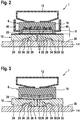
- FIG. 2 shows a schematic cross section through the circuit 1 according to FIG. 1 before the appearance of a warp.
- a spring element 12 presses the circuit module 6 to form a media-filled gap 20 on the Entracermungselement 16, the heat loss peaks of arranged on a multi-layer circuit board 8 components 4, as far as it allows its heat capacity, record and reduce.
- the Entracermungselement 16 lies with its bottom 32 on a larger heat sink 14, which may be, for example, a thermally conductive body part or a transmission housing or a water-cooled engine housing.
- the circuit module has in this embodiment, a gear or motor switching unit, which can issue 40 control signals via angled out of the plastic housing composition 10 outstanding flat conductor contacts.
- the circuit module 6 is pressed by means of a spring member 12 on the segmented Entracermungselement 16 and this in turn on the heat sink 14 or a body part.
- the Entracermungselement 16 is segmented into individual segments 24, as it already is FIG. 1 showed. Each segment has on its underside 32 a recess 30 which serves as a positioning element 26. On the top 36 of the heat sink 14 26 locking elements 28 are arranged in the form of elevations 34 in the region of the positioning, which are applied, for example, by electroplating or by soldering or welding on the top 36 of the heat sink 14.
- FIG. 3 shows a schematic cross section through the circuit 1 according to FIG. 1 after occurrence of warping 18 at a first temperature.
- a convex curvature of the circuit module 6 occurs, whereby the plate-shaped Entracermungssegmente 24 of the Entracermungselements 16 are tilted on the locking elements 28 and thus does not substantially increase the media-filled gap width of the gap 20, since the segments 24 by their tilting to the convex Warp of the circuit module 6 can customize.
- FIG. 4 shows a schematic cross section through the circuit 1 according to FIG. 1 after occurrence of warping at a second temperature.
- a concave warping of the circuit module 6 occurs. Again, it is by segmenting the Entracermungselements 16 possible to keep the media-filled gap 20 between the Entracermungselement 16 and the segments 24 of the Entracermungselements 16 and the concave warping of the circuit module 6 low.
- FIG. 5 shows a schematic cross-section through a circuit arrangement 2 according to a second embodiment of the invention, wherein components with the same functions as in the preceding figures are identified by the same reference numerals and not discussed separately.
- the difference from the previous embodiment according to the FIGS. 1 to 4 is that the heat-absorbing segments 24 of the Entracermungselements 16 are resiliently biased by 14 spring elements 38 are arranged under bias in corresponding spring seats 42 of the heat sink, so that at a Verwölbung the spring elements 38, the segments 24 of the Entracermungselements 16 against the bottom 22nd of the circuit module 6 can press.
- FIG. 6 clearly, in which a schematic cross section through the circuit 2 according to FIG. 5 after occurrence of warpage 18 at a first temperature is shown. Due to the convex curvature 18, the segments 24 are raised by means of outer edge-side spring elements 38 more than by the spring elements 38 which are arranged in the center. It is thereby achieved that the media-filled gap 20 has a minimum width despite the convex curvature 18.
- FIG. 7 shows a corresponding schematic cross section through the circuit 2 according to FIG. 5 after occurrence of a concave warping 18 at a second temperature and illustrates that here the spring elements 38 can lift the segments 24 of the Entracermungselements 16 such that again a small media-filled gap 20 occurs and optimal heat coupling between the circuit module 6 and the Entracermungselement 16 is made possible ,
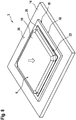
- FIG. 8 shows a perspective sketch of a circuit arrangement 3 of a third embodiment of the invention.
- the plate-shaped Enticarmungselement 16 no segmentation. Nevertheless, the Entracermungselement 16 automatically adapts to the warpage at different operating temperatures of the circuit module 6, since the Entracermungselement 16 consists of a bidirectional shape memory material.
- This shape memory material has the advantage that it can transition from an initial shape to an opposite shape in a transition region, wherein in the temperature transition region the material can change from a first microstructure to a second microstructure, such as in iron alloys from a martensitic microstructure to an austenitic one Structure and vice versa.
- this provides the possibility, after occurrence of a warping at a first temperature that convexly conveys the circuit module 6, that the Entracermungselement 16 assumes a convex shape and thus minimizes the media-filled gap 20.
Description
Die Erfindung betrifft eine elektronische Schaltungsanordnung mit Verlustwärme abgebenden Komponenten eines Schaltungsmoduls. Die Komponenten sind auf einem Schaltungsträger angeordnet und in eine Kunststoffgehäusemasse eingebettet, welche den Schaltungsträger mindestens teilweise umgibt. Die Kunststoffgehäusemasse und der Schaltungsträger weisen unterschiedliche thermische Ausdehnungskoeffizienten auf. Das Schaltungsmodul aus Kunststoffgehäusemasse und Schaltungsträger mit Verlustwärme abgebenden Komponenten ist federelastisch auf einer Wärmesenke fixiert.The invention relates to an electronic circuit arrangement with loss-heat-emitting components of a circuit module. The components are arranged on a circuit carrier and embedded in a plastic housing composition which at least partially surrounds the circuit carrier. The plastic housing composition and the circuit carrier have different thermal expansion coefficients. The circuit module made of plastic housing material and circuit carrier with components that dissipate heat loss is fixed in a spring-elastic manner on a heat sink.
Aus der Druckschrift
Aus der Druckschrift
Aus der Druckschrift
Druckschrift
Außerdem ist aus der Druckschrift
Mit der Erfindung wird eine Schaltungsanordnung mit Verlustwärme abgebenden Komponenten eines Schaltungsmoduls vorgeschlagen, wobei die Komponenten auf einem Schaltungsträger angeordnet und in eine Kunststoffgehäusemasse eingebettet sind, welche den Schaltungsträger mindestens teilweise umgibt. Die Kunststoffgehäusemasse und der Schaltungsträger weisen unterschiedliche thermische Ausdehnungskoeffizienten auf. Das Schaltungsmodul aus Kunststoffgehäusemasse und Schaltungsträger mit Verlustwärme abgebenden Komponenten ist federelastisch auf einer Wärmesenke fixiert. Zwischen der Wärmesenke und dem Schaltungsmodul ist ein wärmeleitendes Entwärmungselement angeordnet. Das Entwärmungselement ist unterschiedlichen Verwölbungen des Schaltungsmoduls bei unterschiedlichen Betriebstemperaturen angepasst.The invention proposes a circuit arrangement with components of a circuit module which dissipate heat loss, wherein the components are arranged on a circuit carrier and embedded in a plastic housing composition which at least partially surrounds the circuit carrier. The plastic housing composition and the circuit carrier have different thermal expansion coefficients. The circuit module made of plastic housing material and circuit carrier with components that dissipate heat loss is fixed in a spring-elastic manner on a heat sink. Between the heat sink and the circuit module, a heat-conducting Entwärmungselement is arranged. The Entwärmungselement is adapted to different warping of the circuit module at different operating temperatures.
Beim Betrieb des Moduls aus einem Schaltungsträger mit den Verlustwärme abgebenden Komponenten und einer die Komponenten einbettenden Kunststoffgehäusemasse, die mindestens teilweise den Schaltungsträger umgibt, kann sich das Modul aufgrund der unterschiedlichen thermischen Ausdehnungskoeffizienten von Kunststoffgehäusemasse und Schaltungsträger verwölben. Eine derartige Verwölbung des Schaltungsmoduls kann je nach Betriebstemperaturbereich des Schaltungsmoduls dieses konkav oder konvex verformen. Dadurch kann sich ein mediengefüllter Spalt zwischen dem Entwärmungselement und dem Schaltungsmodul partiell um ein Vielfaches der ursprünglichen Spaltbreite vergrößern. Aufgrund der partiellen Vergrößerung des Spaltes zwischen Schaltungsmodul und wärmeleitendem Entwärmungselement vergrößert sich der Wärmewiderstand des Mediums, wie Luft, Öl oder nachgiebigem Klebstoff, bzw. vermindert sich partiell die Wärmeleitfähigkeit des mediengefüllten Spaltes bei Ausbildung derartiger Verwölbungen des Schaltungsmoduls, was zu Überhitzungen einzelner Verlustwärme abgebender Komponenten führen kann. Durch die erfindungsgemäße Anpassung der Form des Entwärmungselements an die Verwölbung des Schaltungsmoduls kann dafür gesorgt werden, dass diesem Effekt entgegengewirkt wird.During operation of the module from a circuit carrier with the heat dissipating components and a component embedding plastic housing material that surrounds at least partially the circuit substrate, the module may warp due to the different thermal expansion coefficients of plastic housing material and circuit carrier. Such warping of the circuit module may deform concave or convex depending on the operating temperature range of the circuit module. As a result, a media-filled gap between the Entwärmungselement and the circuit module partially enlarge by a multiple of the original gap width. Due to the partial enlargement of the gap between the circuit module and heat-conducting Entwärmungselement increases the thermal resistance of the medium, such as air, oil or flexible adhesive, or partially reduces the thermal conductivity of the media-filled gap in forming such warping of the circuit module, resulting in overheating of individual heat loss of dispensing components can lead. The inventive adaptation of the shape of the Entwärmungselements to the warping of the circuit module can be taken to ensure that this effect is counteracted.
Der Schaltungsträger kann beispielsweise eine Leiterplatte z.B. ein PCB ("printed circuit board") oder LTTC, DBC oder FR4 oder andere standardisierte, typische Substrate der Halbleitertechnologie aufweisen. Weiterhin können die Schaltungsträger auch mehrlagige Keramiken aufweisen.The circuit carrier may, for example, comprise a printed circuit board, eg a PCB (printed circuit board) or LTTC, DBC or FR4 or other standardized, typical substrates of semiconductor technology. Furthermore, the circuit carriers can also have multilayer ceramics.
Das Entwärmungselement kann zur Anpassung seiner Form an eine Verwölbung des Schaltungsmoduls bei einem ersten Aspekt der Erfindung ein Formgedächtnismaterial aufweisen, dessen Formgedächtnis den temperaturabhängigen Verwölbungen des Schaltungsmoduls angepasst ist. Das Formgedächtnismaterial kann als plattenförmiges, wärmeleitendes Entwärmungselement zwischen der Wärmesenke und dem Schaltungsmodul angeordnet sein und ein bidirektionales Formgedächtnismaterial in Plattenform aufweisen.The Entwärmungselement may have to adapt its shape to a warping of the circuit module in a first aspect of the invention, a shape memory material whose shape memory is adapted to the temperature-dependent warping of the circuit module. The shape memory material may be disposed as a plate-shaped thermally conductive Entwärmungselement between the heat sink and the circuit module and have a bidirectional shape memory material in plate form.
Ein derartiges bidirektionales Formgedächtnismaterial aus einer Metalllegierung kann in Abhängigkeit von der Betriebstemperatur sowohl eine konkave als auch eine konvexe Form in einem vorbestimmten Übergangstemperaturbereich von einem ersten Metallgefügezustand zu einem zweiten Metallgefügezustand wie beispielsweise von einem martensitischen Gefüge in ein austenitisches Gefüge und umgekehrt übergehen. Dabei kann durch die Plattendicke des Formgedächtnismaterials das Entwärmungselement den Verwölbungen des Schaltungsmoduls angepasst sein.Such a metal alloy shape-memory bi-directional material may transition both a concave and a convex shape in a predetermined transition temperature range from a first metal microstructure state to a second metal microstructure state such as a martensitic microstructure into an austenitic microstructure, and vice versa, depending on the operating temperature. In this case, the Entwärmungselement be adapted to the Verwölbungen of the circuit module by the plate thickness of the shape memory material.
Bei einem zweiten Aspekt der Erfindung kann ein plattenförmiges Entwärmungselement segmentiert sein. Die Segmente des Entwärmungselements können auf der Oberfläche der Wärmesenke derart beweglich oder kippbar angeordnet sein, dass sie einer Verwölbung einer Unterseite des Schaltungsmoduls folgen können. Dazu kann jedes der Segmente des Entwärmungselements ein Positionierungselement aufweisen, das mit einem Arretierungselement auf der Wärmesenke in Eingriff steht.In a second aspect of the invention, a plate-shaped Entwärmungselement be segmented. The segments of the heat-dissipation member may be disposed on the surface of the heat sink movable or tiltable so that they may follow a warpage of a bottom of the circuit module. For this purpose, each of the segments of the Entwärmungselements having a positioning element, which is in engagement with a locking element on the heat sink.
Dabei ist es möglich, dass das Positionierungselement eine Aussparung auf einer Unterseite des Segmentes und das Arretierungselement der Wärmesenke eine Erhebung auf einer Oberseite der Wärmesenke aufweisen. Die Aussparung auf der Unterseite des Segmentes kann mit der Erhebung auf der Oberseite der Wärmesenke formschlüssig in Eingriff stehen, so dass keine Platzverschiebung der einzelnen Segmente des Entwärmungselements möglich ist, jedoch eine Verkippung und Ausrichtungsänderung der Segmente zur Anpassung sowohl an eine konkave als auch an eine konvexe Verwölbung des Schaltungsmoduls bereitgestellt wird.It is possible that the positioning element has a recess on an underside of the segment and the locking element of the heat sink a survey on an upper side of the heat sink. The recess on the underside of the segment can be positively engaged with the elevation on the top of the heat sink so that no displacement of the individual segments of the Entwärmungselements is possible, however, a tilting and alignment change of the segments for adaptation to both a concave and a convex warpage of the circuit module is provided.
Formschlüssig zueinander passende Erhebungen und Aussparungen können auch umgekehrt vorgesehen werden, so dass das Positionierungselement auf der Unterseite des Segmentes als Erhebung ausgebildet ist und das Arretierungselement auf der Oberseite der Wärmesenke als Aussparung vorbereitet ist. Als Erhebung können Schweiß- oder Löttropfen auf eine Oberseite oder Unterseite aufgebracht sein oder es können halbkugelförmige Elemente aufgeschweißt, galvanisch abgeschieden oder als Löttropfen auf entsprechende Metallflächen aufgebracht sein. Dabei können die Erhebungen eine Kugelform, eine Halbkugelform oder ein sonstiges erhabenes Element ausbilden. Auch kann als Erhebung ein Nietkopf oder ein Einpresspin vorgesehen sein.Positive fit mounts and recesses may also be provided vice versa, so that the positioning element on the underside of Segment is formed as a survey and the locking element is prepared on the top of the heat sink as a recess. As a survey welding or soldering drops can be applied to a top or bottom or it can be welded hemispherical elements, electrodeposited or applied as solder drops on corresponding metal surfaces. The elevations may form a spherical shape, a hemisphere shape or any other raised element. Also may be provided as survey a rivet head or a press-in pin.
Anstelle derartiger Erhebungen und Aussparungen ist es auch möglich, zwischen einem plattenförmigen Segment des Entwärmungselements und der Oberseite der Wärmesenke jeweils mindestens ein Federelement anzuordnen, wobei jedes Federelement das entsprechende Segment des Entwärmungselements gegen die verwölbte Unterseite des Schaltungsmoduls presst.Instead of such elevations and recesses, it is also possible to arrange at least one spring element between a plate-shaped segment of the Entwärmungselements and the upper side of the heat sink, wherein each spring element presses the corresponding segment of the Entwärmungselements against the warped underside of the circuit module.
Weiterhin ist es vorgesehen, dass das Segment oder die Wärmesenke oder beide an korrespondierenden Positionen an das Federelement angepasste Aussparungen aufweisen. Diese Aussparungen sorgen dafür, dass die Federelemente ihre Positionen unter den Segmenten beibehalten. Die Federelemente können auch dazu mit einem Ende an der Unterseite des Segmentes oder an der Oberseite der Wärmesenke stoffschlüssig fixiert sein, während das andere Ende das Federelements in eine der vorgesehenen Aussparungen eingepasst ist. Als Federelemente können alle Arten von Druckfedern, wie Schraubenfedern, Schenkelfedern, Wiegefedern oder vergleichbare Federelemente, vorgesehen werden.Furthermore, it is provided that the segment or the heat sink or both have at corresponding positions on the spring element adapted recesses. These recesses ensure that the spring elements maintain their positions under the segments. The spring elements can also be fixed cohesively with one end at the bottom of the segment or at the top of the heat sink, while the other end of the spring element is fitted into one of the recesses provided. As spring elements, all types of compression springs, such as coil springs, torsion springs, cradles or similar spring elements can be provided.
Die Erfindung kann auf ein Schaltungsmodul einer Getriebe- oder Motorsteuereinheit eines Kraftfahrzeugs angewandt werden, wobei der Schaltungsträger des Schaltungsmoduls beispielsweise eine Schaltungsplatine mit Leiterbahnen umfasst. Auf dem Schaltungsträger können ein oder mehrere elektronische Bauelemente als Komponenten einschließlich elektronischer Schaltungen wie ICs ("integrated circuits"), Mikroprozessorchips, Logikchips, integrierte Halbleiterchips und/oder passive elektronische Komponenten, wie Widerstände, Kondensatoren oder Induktivitäten oder aktive Steuerelemente wie Transistoren usw. angeordnet sein. Der Schaltungsträger kann auch einen Flachleiterrahmen aufweisen, auf dem Verlustwärme abgebende Komponenten, wie integrierte Schaltungen mit Leistungstransistoren zur Leistungsversorgung, Mikroprozessoren oder Logikschaltungen, vorgesehen sind, wobei der Flachleiterrahmen in einer Kunststoffgehäusemasse eingebettet ist, aus der Flachleiteranschlüsse als Außenkontakte des Schaltungsmoduls herausragen.The invention can be applied to a circuit module of a transmission or engine control unit of a motor vehicle, wherein the circuit carrier of the circuit module comprises, for example, a circuit board with conductor tracks. On the circuit carrier may be one or more electronic components as components including electronic circuits such as ICs ("integrated circuits"), microprocessor chips, logic chips, integrated semiconductor chips and / or passive electronic components such as resistors, capacitors or inductors or active controls such as transistors, etc. arranged be. The circuit carrier can also have a leadframe on which components which dissipate heat loss, such as integrated circuits with power transistors for power supply, microprocessors or logic circuits are provided, wherein the leadframe is embedded in a plastic housing composition, protrude from the flat conductor terminals as external contacts of the circuit module.
Eine Wärmesenke für eine derartige Getriebe- oder Motorsteuereinheit eines Kraftfahrzeugs kann ein metallisches Karosserieteil, ein Getriebegehäuse oder ein wassergekühltes Verbrennungsmotorgehäuse eines Kraftfahrzeugs bilden. Die thermische Verbindung zu dem Schaltungsmodul kann durch die Anordnung des erfindungsgemäßen Entwärmungselements optimiert werden. Das Entwärmungselement kann sich an Verwölbungen des Schaltungsmoduls selbsttätig anpassen.A heat sink for such a transmission or engine control unit of a motor vehicle may form a metallic body part, a transmission housing or a water-cooled internal combustion engine housing of a motor vehicle. The thermal connection to the circuit module can be optimized by the arrangement of the Entwärmungselements invention. The Entwärmungselement can adapt itself to Verwölbungen the circuit module automatically.
Mit der Erfindung ist der Vorteil verbunden, dass der sich beim federelastischen Fixieren des Schaltungsmoduls auf einer Oberseite einer Wärmesenke in Form eines Karosserieteils eines Getriebegehäuses oder eines wassergekühlten Verbrennungsmotorgehäuses eines Fahrzeugs ausbildende mediengefüllte Spalt, der sich bei unterschiedlichen Betriebsbedingungen und Temperaturen des Fahrzeugs durch Verwölbungen des Schaltungsmoduls partiell vergrößert, durch das Entwärmungselement thermisch kompensiert wird. Durch die Anpassungsfähigkeit des Entwärmungselements zwischen der Wärmesenke und dem Schaltungsmodul kann der Spalt zwischen Schaltungsmodul und Entwärmungselement auf ein Minimum einer Spaltbreite zwischen verwölbtem Schaltungsmodul und angepasstem Entwärmungselement reduziert werden. Wärme, die aus dem Schaltungsmodul abgeführt werden muss, kann somit in optimaler Weise von dem Schaltungsmodul auf die zusätzliche Wärmesenke, die das Entwärmungselement bildet, übertragen und von dem Schaltungsträger abgeführt werden.The invention has the advantage that the media-filled gap forming during resilient fixing of the circuit module on an upper side of a heat sink in the form of a body part of a transmission housing or of a water-cooled internal combustion engine housing of a vehicle, resulting from warping of the circuit module at different operating conditions and temperatures of the vehicle partially enlarged, is thermally compensated by the Entwärmungselement. Due to the adaptability of the heat dissipation element between the heat sink and the circuit module, the gap between the circuit module and the heat dissipation element can be reduced to a minimum of a gap width between warped circuit module and matched heat dissipation element. Heat that must be dissipated from the circuit module can thus be optimally transferred from the circuit module to the additional heat sink that forms the cooling element and dissipated from the circuit carrier.
Das in mehrere Segmentplatten segmentierte Entwärmungselement kann flexibel auf Verwölbungen eines Schaltungsmoduls, bestehend aus Schaltungsträger mit Verlustwärme abgebenden Komponenten, reagieren, indem es seine Form derart anpasst, dass sich trotz Ausbildung von Verwölbungen des Schaltungsmoduls ein nahezu gleichmäßig verminderter, mediengefüllter Spalt zwischen dem Entwärmungselement und dem Schaltungsmodul bildet.The heat-dissipating element segmented into a plurality of segment plates can react flexibly to warping of a circuit module consisting of circuit carriers with dissipating heat-dissipating components by adapting its shape such that, despite the formation of warping of the circuit module, an almost uniformly reduced, media-filled gap between the cooling element and the heat dissipation element Circuit module forms.
Mit der Erfindung können Erwärmungsspitzen der Komponenten aufgrund der zusätzlichen Wärmekapazität des Entwärmungselements und der relativ gleich bleibenden Wärmeleitung zwischen dem Schaltungsmodul und dem Entwärmungselement, trotz Verwölbung des Schaltungsmoduls, ausgeglichen werden.With the invention, heating spikes of the components due to the additional heat capacity of the Entwärmungselements and the relatively constant heat conduction between the circuit module and the Entwärmungselement, despite warping of the circuit module, can be compensated.
Durch das Selbstanpassen des Entwärmungselements kann die Gefahr einer lokalen Überhitzung des Schaltungsmoduls vermindert werden, da der Wärmetransport von der in Kunststoffmasse eingebetteten, elektronischen Steuereinheit eines Getriebes oder Verbrennungsmotors durch das Entwärmungselement, das zwischen der elektronischen Steuereinheit in Form eines Schaltungsmoduls und der Wärmesenke in Form eines wärmeleitenden Karosserieteils oder eines wärmeleitenden Gehäuses eines Getriebes oder eines wassergekühlten Verbrennungsmotors angeordnet ist, verbessert wird, zumal das formanpassbare Entwärmungselement die Verwölbungen des Schaltungsmoduls, die während der Temperaturzyklen auftreten, kompensiert.The self-adaptation of the Entwärmungselements the risk of local overheating of the circuit module can be reduced because the heat transfer from the embedded in plastic material, electronic control unit of a transmission or internal combustion engine by the Entwärmungselement that between the electronic control unit in the form of a circuit module and the heat sink in the form of a thermally conductive body part or a heat-conducting housing of a transmission or a water-cooled internal combustion engine is improved, especially since the conformable Entwärmungselement compensates for the warpage of the circuit module, which occur during the temperature cycles.
Ein in mehrere Segmente aufgeteiltes Entwärmungselement aus einem Material mit hohem Wärmeleitungskoeffizient stellt eine zusätzliche Wärmesenke dar, die den Verwölbungen des Schaltungsmoduls folgt, wobei die plattenförmigen Segmente des Entwärmungselements auf dem Getriebe- oder Verbrennungsmotorgehäuse auf den Erhebungen, sphärischen Buckeln oder Serien von Federn angeordnet sein können, so dass in vorteilhafter Weise Ausrichtungen des Entwärmungselements aus einzelnen Segmentplatten während der Temperaturänderungen derart geändert werden können, dass die Wärmeübertragungsbedingungen jederzeit optimiert bleiben.A multi-segment heat dissipation element made of a high thermal conductivity material material provides an additional heat sink following the warping of the circuit module, wherein the plate-shaped segments of the heat-dissipation element may be disposed on the transmission or combustion engine housing on the bumps, spherical bumps or series of springs so that, advantageously, alignments of the cooling element from individual segment plates during the temperature changes can be changed such that the heat transfer conditions remain optimized at all times.
Weiterhin ist es von Vorteil bei einer federelastischen Vorspannung der Segmente des Entwärmungselements, dass jede einzelne Feder für ein einzelnes Segment des Entwärmungselements in einer Aussparung entweder auf der Oberseite der Wärmesenke oder auf der Unterseite des einzelnen wärmeleitenden Segmentes des Entwärmungselements angeordnet ist und somit die Federelemente ihre Positionen auch beim Ändern von Betriebsbedingungen beibehalten.Furthermore, it is advantageous in a resilient bias of the segments of the Entwärmungselements that each spring is arranged for a single segment of the Entwärmungselements in a recess either on top of the heat sink or on the underside of the individual heat-conducting segment of the Entwärmungselements and thus the spring elements their Keep positions even when changing operating conditions.
Von Vorteil ist eine weitere Optimierung durch Einsatz von Formgedächtnismaterialien für das plattenförmige Entwärmungselement, zumal bidirektionale Formgedächtnismaterialien sowohl konkave als auch konvexe Verformungen bei vorgegebenen Übergangstemperaturbereichen einnehmen und damit den Spalt zwischen einem konkav oder konvex verwölbtem Schaltungsmodus in optimaler Weise minimieren können.Another advantage is a further optimization by the use of shape memory materials for the plate-shaped Entwärmungselement, especially since bidirectional shape memory materials both concave and convex deformations take at predetermined transition temperature ranges and thus optimally minimize the gap between a concave or convex warped circuit mode.
Weitere Aspekte und Vorteile der Erfindung werden nunmehr anhand der beigefügten Figuren eingehender beschrieben. Hierbei zeigt:
- Fig. 1
- eine perspektivische Skizze einer Schaltungsanordnung einer ersten Ausführungsform der Erfindung;
- Fig. 2
- einen schematischen Querschnitt durch die Schaltungsanordnung gemäß
Fig. 1 vor dem Auftreten einer Verwölbung; - Fig. 3
- einen schematischen Querschnitt durch die Schaltungsanordnung gemäß
Fig. 1 nach Auftreten einer Verwölbung bei einer ersten Temperatur; - Fig. 4
- einen schematischen Querschnitt durch die Schaltungsanordnung gemäß
Fig. 1 nach Auftreten einer Verwölbung bei einer zweiten Temperatur; - Fig. 5
- einen schematischen Querschnitt durch die Schaltungsanordnung gemäß einer zweiten Ausführungsform der Erfindung;
- Fig. 6
- einen schematischen Querschnitt durch die Schaltungsanordnung gemäß
Fig. 5 nach Auftreten einer Verwölbung bei einer ersten Temperatur; - Fig. 7
- einen schematischen Querschnitt durch die Schaltungsanordnung gemäß
Fig. 5 nach Auftreten einer Verwölbung bei einer zweiten Temperatur; - Fig. 8
- eine perspektivische Skizze einer Schaltungsanordnung einer dritten Ausführungsform der Erfindung;
- Fig. 9
- einen schematischen Querschnitt durch die Schaltungsanordnung gemäß
Fig. 8 nach Auftreten einer Verwölbung bei einer ersten Temperatur; - Fig. 10
- einen schematischen Querschnitt durch die Schaltungsanordnung gemäß
Fig. 8 nach Auftreten einer Verwölbung bei einer zweiten Temperatur.
- Fig. 1
- a perspective sketch of a circuit arrangement of a first embodiment of the invention;
- Fig. 2
- a schematic cross section through the circuit according to
Fig. 1 before the occurrence of warping; - Fig. 3
- a schematic cross section through the circuit according to
Fig. 1 after occurrence of warping at a first temperature; - Fig. 4
- a schematic cross section through the circuit according to
Fig. 1 after occurrence of warping at a second temperature; - Fig. 5
- a schematic cross section through the circuit arrangement according to a second embodiment of the invention;
- Fig. 6
- a schematic cross section through the circuit according to
Fig. 5 after occurrence of warping at a first temperature; - Fig. 7
- a schematic cross section through the circuit according to
Fig. 5 after occurrence of warping at a second temperature; - Fig. 8
- a perspective sketch of a circuit arrangement of a third embodiment of the invention;
- Fig. 9
- a schematic cross section through the circuit according to
Fig. 8 after occurrence of warping at a first temperature; - Fig. 10
- a schematic cross section through the circuit according to
Fig. 8 after occurrence of warping at a second temperature.
Die in
In dieser ersten Ausführungsform der Erfindung ist das plattenförmige Entwärmungselement 16 in vier Segmente 24 aufgeteilt, die gegenüber einer Oberseite 36 einer Wärmesenke kippbar angeordnet sind, so dass sich die Entwärmungssegmente 24 durch Verkippen an eine Verwölbung auf der Unterseite 22 des Schaltungsmoduls 6 anpassen können. In Pfeilrichtung A wird auf das Schaltungsmodul 6 ein Federdruck ausgeübt, der das Schaltungsmodul 6 auf das plattenförmige Entwärmungselement 16 als eine erste Wärmesenke presst. Das Entwärmungselement 16 wird wiederum mit seinen Entwärmungssegmenten 24 auf die Oberseite 36 einer zweiten größeren Wärmesenke 14 beispielsweise in Form eines Karosserieteils oder eines Getriebegehäuses oder eines wassergekühlten Verbrennungsmotors eines Kraftfahrzeugs gepresst. Trotz dieser in Pfeilrichtung A wirkenden Federkraft kann sich das Schaltungsmodul 6 verwölben, da die Kunststoffgehäusemasse 10 einen von einer als Schaltungsträger eingesetzten Schaltungsplatine unterschiedlichen thermischen Ausdehnungskoeffizienten aufweist.In this first embodiment of the invention, the plate-shaped
Aufgrund des unterschiedlichen thermischen Ausdehnungskoeffizienten zwischen Kunststoffgehäusemasse und dem umhüllten Schaltungsträger 8 können Verwölbungen auftreten, die den in
In dieser ersten Ausführungsform der Erfindung gemäß
Das wird mit der
Wie
Umgekehrt kann bei einer zweiten Temperatur, wie
Claims (8)
- Electronic circuit arrangement with components (4) of a circuit module (6) that emit lost heat and with- a circuit carrier (8), on which the components (4) are arranged;- a plastic housing mass (10), in which the components (4) are embedded, the plastic housing mass (10) at least partially surrounding the circuit carrier (8) and the plastic housing mass (10) and the circuit carrier (8) having different coefficients of thermal expansion;- at least one spring element (12), with which the circuit module (6) comprising the plastic housing mass (10) and the circuit carrier (8) is fixed resiliently on a heat sink (14),a heat-conducting cooling element (16) being arranged between the heat sink (14) and the circuit module (6), and the cooling element (16) being adapted to distortions (18) of the circuit module (6) at different operating temperatures, characterized in that the cooling element (16) comprises a heat-conducting shape memory material, the shape memory of which is adapted to the temperature-dependent distortions (18) of the circuit module (6), or the cooling element (16) is segmented, and the segments (24) of the cooling element (16) are arranged tiltably on a surface (36) of the heat sink (14).
- Circuit arrangement according to Claim 1, the circuit arrangement (1, 2) having a media-filled gap (20) between the cooling element (16) and the circuit module (6).
- Circuit arrangement according to Claim 1 or 2,
the shape memory material having a transition temperature range from a first crystalline state to a second crystalline state and thereby forming a change in shape that is adapted to the distortion (18) of the circuit module (6). - Circuit arrangement according to Claim 1 or 2,
each segment (24) of the cooling element (16) having a positioning element (26), which is in engagement with an arresting element (28) on the heat sink (14). - Circuit arrangement according to Claim 4,
the positioning element (26) having a recess (30) on an underside (32) of the segment (24) and the arresting element (28) of the heat sink (14) having an elevation (34) on an upper side (36) of the heat sink (14), and the recess (30) and the elevation (34) being in form-fitting engagement. - Circuit arrangement according to Claim 1 or 2,
a spring element (38) being arranged between a segment (24) and the upper side (36) of the heat sink (14), and the spring element (38) pressing the segment (24) of the cooling element (16) against the underside (22) of the circuit module (6). - Circuit arrangement according to one of the preceding claims,
the circuit module (6) having a gearbox or engine control unit of a motor vehicle with microprocessor chips, logic chips, integrated semiconductor chips and/or passive electronic components, such as resistors, capacitors or inductances on a circuit board as the circuit carrier (8). - Circuit arrangement according to one of the preceding claims,
the heat sink (14) being a metal body part, a gearbox housing or a water-cooled combustion engine housing of a motor vehicle.
Applications Claiming Priority (3)
| Application Number | Priority Date | Filing Date | Title |
|---|---|---|---|
| DE102011077675 | 2011-06-17 | ||
| DE201210208767 DE102012208767A1 (en) | 2011-06-17 | 2012-05-24 | Electronic circuit with loss of heat emitting components |
| PCT/EP2012/060160 WO2012171797A1 (en) | 2011-06-17 | 2012-05-30 | Electronic circuit arrangement having components emitting lost heat |
Publications (2)
| Publication Number | Publication Date |
|---|---|
| EP2721637A1 EP2721637A1 (en) | 2014-04-23 |
| EP2721637B1 true EP2721637B1 (en) | 2017-01-04 |
Family
ID=47228624
Family Applications (1)
| Application Number | Title | Priority Date | Filing Date |
|---|---|---|---|
| EP12727624.4A Not-in-force EP2721637B1 (en) | 2011-06-17 | 2012-05-30 | Electronic circuit arrangement having components emitting lost heat |
Country Status (3)
| Country | Link |
|---|---|
| EP (1) | EP2721637B1 (en) |
| DE (1) | DE102012208767A1 (en) |
| WO (1) | WO2012171797A1 (en) |
Families Citing this family (3)
| Publication number | Priority date | Publication date | Assignee | Title |
|---|---|---|---|---|
| CN110970377B (en) * | 2019-12-18 | 2021-07-20 | 若瑞(上海)文化科技有限公司 | Packaging device convenient for packaging integrated circuit chip |
| US11582866B1 (en) * | 2021-07-22 | 2023-02-14 | Toyota Motor Engineering & Manufacturing North America, Inc. | Systems including a power device-embedded PCB directly joined with a cooling assembly and method of forming the same |
| DE102022100684B3 (en) | 2022-01-13 | 2023-06-07 | Audi Aktiengesellschaft | Thermal coupling element |
Family Cites Families (10)
| Publication number | Priority date | Publication date | Assignee | Title |
|---|---|---|---|---|
| FR2629153B1 (en) | 1988-03-22 | 1990-05-04 | Bull Sa | DEVICE FOR PRESSURE FIXING OF TWO PIECES TO ONE ANOTHER |
| US7177156B2 (en) | 2004-07-08 | 2007-02-13 | Cray Inc. | Assemblies for holding heat sinks and other structures in contact with electronic devices and other apparatuses |
| JP4621531B2 (en) * | 2005-04-06 | 2011-01-26 | 株式会社豊田自動織機 | Heat dissipation device |
| DE102006045939B4 (en) * | 2006-09-28 | 2021-06-02 | Infineon Technologies Ag | Power semiconductor module with improved stability against temperature changes |
| US7511961B2 (en) * | 2006-10-26 | 2009-03-31 | Infineon Technologies Ag | Base plate for a power semiconductor module |
| JP2008235674A (en) * | 2007-03-22 | 2008-10-02 | Toyota Motor Corp | Power module and vehicle inverter |
| JP4832419B2 (en) * | 2007-12-25 | 2011-12-07 | トヨタ自動車株式会社 | Semiconductor module |
| DE102008009510B3 (en) * | 2008-02-15 | 2009-07-16 | Danfoss Silicon Power Gmbh | Method for low-temperature pressure sintering |
| JP4607995B2 (en) * | 2008-11-28 | 2011-01-05 | 三菱電機株式会社 | Power semiconductor device |
| DE102009002191B4 (en) * | 2009-04-03 | 2012-07-12 | Infineon Technologies Ag | Power semiconductor module, power semiconductor module assembly, and method of making a power semiconductor module assembly |
-
2012
- 2012-05-24 DE DE201210208767 patent/DE102012208767A1/en not_active Withdrawn
- 2012-05-30 WO PCT/EP2012/060160 patent/WO2012171797A1/en active Application Filing
- 2012-05-30 EP EP12727624.4A patent/EP2721637B1/en not_active Not-in-force
Non-Patent Citations (1)
| Title |
|---|
| None * |
Also Published As
| Publication number | Publication date |
|---|---|
| EP2721637A1 (en) | 2014-04-23 |
| DE102012208767A1 (en) | 2012-12-20 |
| WO2012171797A1 (en) | 2012-12-20 |
Similar Documents
| Publication | Publication Date | Title |
|---|---|---|
| DE102006028675B4 (en) | Cooling arrangement for arranged on a support plate electrical components | |
| DE102007019885B4 (en) | Heatsink with matrix-structured surface | |
| DE10351934B4 (en) | Light-emitting diode arrangement with heat dissipating board | |
| EP2439774A2 (en) | Heat distributor with flexible heat tube | |
| EP0654820B1 (en) | Semiconductor module with convex base plate | |
| DE102005049872B4 (en) | IC component with cooling arrangement | |
| DE102006058347B4 (en) | Structure of a power module and this using semiconductor relay | |
| DE102006008807B4 (en) | Arrangement with a power semiconductor module and a cooling component | |
| DE102009001722B4 (en) | Method for applying a heat transfer medium to a heat dissipation surface | |
| DE102012201172B4 (en) | Method for producing a power semiconductor module with embossed base plate | |
| DE102004018476A1 (en) | A power semiconductor device | |
| EP1791177A1 (en) | Semiconductor unit with improved heat coupling | |
| EP2721637B1 (en) | Electronic circuit arrangement having components emitting lost heat | |
| DE102017212233A1 (en) | Electrical assembly and method of making an electrical assembly | |
| US6918437B2 (en) | Heatsink buffer configuration | |
| DE102020207150A1 (en) | DEVICE FOR HEAT MANAGEMENT OF ELECTRONIC COMPONENTS | |
| EP2439775B1 (en) | Heat distributor with mechanically secured heat coupling element | |
| DE202013002411U1 (en) | Heat spreader with flat tube cooling element | |
| WO2009050130A2 (en) | Chip cooling device having wedge element | |
| EP2114116B1 (en) | Hybrid cooling | |
| DE3212592C2 (en) | Cooling device for communications engineering equipment | |
| DE10249436A1 (en) | Heat sink for cooling power component on circuit board, has recess which receives power component, while establishing thermal contact between planar surfaces of heat sink and circuit board | |
| DE102007052397B4 (en) | Cooling arrangement for thermal contacting between the electronic component and the heat sink | |
| DE102005012216B4 (en) | Surface mounted semiconductor device with heat sink and mounting method | |
| EP2006910B1 (en) | Power electronics module |
Legal Events
| Date | Code | Title | Description |
|---|---|---|---|
| PUAI | Public reference made under article 153(3) epc to a published international application that has entered the european phase |
Free format text: ORIGINAL CODE: 0009012 |
|
| 17P | Request for examination filed |
Effective date: 20140117 |
|
| AK | Designated contracting states |
Kind code of ref document: A1 Designated state(s): AL AT BE BG CH CY CZ DE DK EE ES FI FR GB GR HR HU IE IS IT LI LT LU LV MC MK MT NL NO PL PT RO RS SE SI SK SM TR |
|
| DAX | Request for extension of the european patent (deleted) | ||
| GRAP | Despatch of communication of intention to grant a patent |
Free format text: ORIGINAL CODE: EPIDOSNIGR1 |
|
| INTG | Intention to grant announced |
Effective date: 20161010 |
|
| GRAS | Grant fee paid |
Free format text: ORIGINAL CODE: EPIDOSNIGR3 |
|
| GRAA | (expected) grant |
Free format text: ORIGINAL CODE: 0009210 |
|
| AK | Designated contracting states |
Kind code of ref document: B1 Designated state(s): AL AT BE BG CH CY CZ DE DK EE ES FI FR GB GR HR HU IE IS IT LI LT LU LV MC MK MT NL NO PL PT RO RS SE SI SK SM TR |
|
| REG | Reference to a national code |
Ref country code: GB Ref legal event code: FG4D Free format text: NOT ENGLISH |
|
| REG | Reference to a national code |
Ref country code: CH Ref legal event code: EP |
|
| REG | Reference to a national code |
Ref country code: AT Ref legal event code: REF Ref document number: 859997 Country of ref document: AT Kind code of ref document: T Effective date: 20170115 |
|
| REG | Reference to a national code |
Ref country code: IE Ref legal event code: FG4D Free format text: LANGUAGE OF EP DOCUMENT: GERMAN |
|
| REG | Reference to a national code |
Ref country code: DE Ref legal event code: R096 Ref document number: 502012009217 Country of ref document: DE |
|
| REG | Reference to a national code |
Ref country code: LT Ref legal event code: MG4D Ref country code: NL Ref legal event code: MP Effective date: 20170104 |
|
| REG | Reference to a national code |
Ref country code: FR Ref legal event code: PLFP Year of fee payment: 6 |
|
| PG25 | Lapsed in a contracting state [announced via postgrant information from national office to epo] |
Ref country code: NL Free format text: LAPSE BECAUSE OF FAILURE TO SUBMIT A TRANSLATION OF THE DESCRIPTION OR TO PAY THE FEE WITHIN THE PRESCRIBED TIME-LIMIT Effective date: 20170104 |
|
| PG25 | Lapsed in a contracting state [announced via postgrant information from national office to epo] |
Ref country code: NO Free format text: LAPSE BECAUSE OF FAILURE TO SUBMIT A TRANSLATION OF THE DESCRIPTION OR TO PAY THE FEE WITHIN THE PRESCRIBED TIME-LIMIT Effective date: 20170404 Ref country code: LT Free format text: LAPSE BECAUSE OF FAILURE TO SUBMIT A TRANSLATION OF THE DESCRIPTION OR TO PAY THE FEE WITHIN THE PRESCRIBED TIME-LIMIT Effective date: 20170104 Ref country code: FI Free format text: LAPSE BECAUSE OF FAILURE TO SUBMIT A TRANSLATION OF THE DESCRIPTION OR TO PAY THE FEE WITHIN THE PRESCRIBED TIME-LIMIT Effective date: 20170104 Ref country code: HR Free format text: LAPSE BECAUSE OF FAILURE TO SUBMIT A TRANSLATION OF THE DESCRIPTION OR TO PAY THE FEE WITHIN THE PRESCRIBED TIME-LIMIT Effective date: 20170104 Ref country code: GR Free format text: LAPSE BECAUSE OF FAILURE TO SUBMIT A TRANSLATION OF THE DESCRIPTION OR TO PAY THE FEE WITHIN THE PRESCRIBED TIME-LIMIT Effective date: 20170405 Ref country code: IS Free format text: LAPSE BECAUSE OF FAILURE TO SUBMIT A TRANSLATION OF THE DESCRIPTION OR TO PAY THE FEE WITHIN THE PRESCRIBED TIME-LIMIT Effective date: 20170504 |
|
| PG25 | Lapsed in a contracting state [announced via postgrant information from national office to epo] |
Ref country code: SE Free format text: LAPSE BECAUSE OF FAILURE TO SUBMIT A TRANSLATION OF THE DESCRIPTION OR TO PAY THE FEE WITHIN THE PRESCRIBED TIME-LIMIT Effective date: 20170104 Ref country code: PT Free format text: LAPSE BECAUSE OF FAILURE TO SUBMIT A TRANSLATION OF THE DESCRIPTION OR TO PAY THE FEE WITHIN THE PRESCRIBED TIME-LIMIT Effective date: 20170504 Ref country code: LV Free format text: LAPSE BECAUSE OF FAILURE TO SUBMIT A TRANSLATION OF THE DESCRIPTION OR TO PAY THE FEE WITHIN THE PRESCRIBED TIME-LIMIT Effective date: 20170104 Ref country code: PL Free format text: LAPSE BECAUSE OF FAILURE TO SUBMIT A TRANSLATION OF THE DESCRIPTION OR TO PAY THE FEE WITHIN THE PRESCRIBED TIME-LIMIT Effective date: 20170104 Ref country code: RS Free format text: LAPSE BECAUSE OF FAILURE TO SUBMIT A TRANSLATION OF THE DESCRIPTION OR TO PAY THE FEE WITHIN THE PRESCRIBED TIME-LIMIT Effective date: 20170104 Ref country code: LU Free format text: LAPSE BECAUSE OF NON-PAYMENT OF DUE FEES Effective date: 20170531 Ref country code: BG Free format text: LAPSE BECAUSE OF FAILURE TO SUBMIT A TRANSLATION OF THE DESCRIPTION OR TO PAY THE FEE WITHIN THE PRESCRIBED TIME-LIMIT Effective date: 20170404 Ref country code: ES Free format text: LAPSE BECAUSE OF FAILURE TO SUBMIT A TRANSLATION OF THE DESCRIPTION OR TO PAY THE FEE WITHIN THE PRESCRIBED TIME-LIMIT Effective date: 20170104 |
|
| REG | Reference to a national code |
Ref country code: DE Ref legal event code: R097 Ref document number: 502012009217 Country of ref document: DE |
|
| PG25 | Lapsed in a contracting state [announced via postgrant information from national office to epo] |
Ref country code: CZ Free format text: LAPSE BECAUSE OF FAILURE TO SUBMIT A TRANSLATION OF THE DESCRIPTION OR TO PAY THE FEE WITHIN THE PRESCRIBED TIME-LIMIT Effective date: 20170104 Ref country code: RO Free format text: LAPSE BECAUSE OF FAILURE TO SUBMIT A TRANSLATION OF THE DESCRIPTION OR TO PAY THE FEE WITHIN THE PRESCRIBED TIME-LIMIT Effective date: 20170104 Ref country code: EE Free format text: LAPSE BECAUSE OF FAILURE TO SUBMIT A TRANSLATION OF THE DESCRIPTION OR TO PAY THE FEE WITHIN THE PRESCRIBED TIME-LIMIT Effective date: 20170104 Ref country code: SK Free format text: LAPSE BECAUSE OF FAILURE TO SUBMIT A TRANSLATION OF THE DESCRIPTION OR TO PAY THE FEE WITHIN THE PRESCRIBED TIME-LIMIT Effective date: 20170104 |
|
| PLBE | No opposition filed within time limit |
Free format text: ORIGINAL CODE: 0009261 |
|
| STAA | Information on the status of an ep patent application or granted ep patent |
Free format text: STATUS: NO OPPOSITION FILED WITHIN TIME LIMIT |
|
| PG25 | Lapsed in a contracting state [announced via postgrant information from national office to epo] |
Ref country code: DK Free format text: LAPSE BECAUSE OF FAILURE TO SUBMIT A TRANSLATION OF THE DESCRIPTION OR TO PAY THE FEE WITHIN THE PRESCRIBED TIME-LIMIT Effective date: 20170104 Ref country code: SM Free format text: LAPSE BECAUSE OF FAILURE TO SUBMIT A TRANSLATION OF THE DESCRIPTION OR TO PAY THE FEE WITHIN THE PRESCRIBED TIME-LIMIT Effective date: 20170104 |
|
| 26N | No opposition filed |
Effective date: 20171005 |
|
| REG | Reference to a national code |
Ref country code: CH Ref legal event code: PL |
|
| PG25 | Lapsed in a contracting state [announced via postgrant information from national office to epo] |
Ref country code: MC Free format text: LAPSE BECAUSE OF FAILURE TO SUBMIT A TRANSLATION OF THE DESCRIPTION OR TO PAY THE FEE WITHIN THE PRESCRIBED TIME-LIMIT Effective date: 20170104 |
|
| REG | Reference to a national code |
Ref country code: IE Ref legal event code: MM4A |
|
| PG25 | Lapsed in a contracting state [announced via postgrant information from national office to epo] |
Ref country code: CH Free format text: LAPSE BECAUSE OF NON-PAYMENT OF DUE FEES Effective date: 20170531 Ref country code: SI Free format text: LAPSE BECAUSE OF FAILURE TO SUBMIT A TRANSLATION OF THE DESCRIPTION OR TO PAY THE FEE WITHIN THE PRESCRIBED TIME-LIMIT Effective date: 20170104 Ref country code: LI Free format text: LAPSE BECAUSE OF NON-PAYMENT OF DUE FEES Effective date: 20170531 |
|
| PG25 | Lapsed in a contracting state [announced via postgrant information from national office to epo] |
Ref country code: LU Free format text: LAPSE BECAUSE OF NON-PAYMENT OF DUE FEES Effective date: 20170530 |
|
| REG | Reference to a national code |
Ref country code: BE Ref legal event code: MM Effective date: 20170531 |
|
| PG25 | Lapsed in a contracting state [announced via postgrant information from national office to epo] |
Ref country code: IE Free format text: LAPSE BECAUSE OF NON-PAYMENT OF DUE FEES Effective date: 20170530 |
|
| REG | Reference to a national code |
Ref country code: FR Ref legal event code: PLFP Year of fee payment: 7 |
|
| REG | Reference to a national code |
Ref country code: AT Ref legal event code: MM01 Ref document number: 859997 Country of ref document: AT Kind code of ref document: T Effective date: 20170530 |
|
| PG25 | Lapsed in a contracting state [announced via postgrant information from national office to epo] |
Ref country code: BE Free format text: LAPSE BECAUSE OF NON-PAYMENT OF DUE FEES Effective date: 20170531 Ref country code: AT Free format text: LAPSE BECAUSE OF NON-PAYMENT OF DUE FEES Effective date: 20170530 |
|
| PG25 | Lapsed in a contracting state [announced via postgrant information from national office to epo] |
Ref country code: MT Free format text: LAPSE BECAUSE OF FAILURE TO SUBMIT A TRANSLATION OF THE DESCRIPTION OR TO PAY THE FEE WITHIN THE PRESCRIBED TIME-LIMIT Effective date: 20170104 |
|
| PG25 | Lapsed in a contracting state [announced via postgrant information from national office to epo] |
Ref country code: HU Free format text: LAPSE BECAUSE OF FAILURE TO SUBMIT A TRANSLATION OF THE DESCRIPTION OR TO PAY THE FEE WITHIN THE PRESCRIBED TIME-LIMIT; INVALID AB INITIO Effective date: 20120530 |
|
| PG25 | Lapsed in a contracting state [announced via postgrant information from national office to epo] |
Ref country code: CY Free format text: LAPSE BECAUSE OF NON-PAYMENT OF DUE FEES Effective date: 20170104 |
|
| PG25 | Lapsed in a contracting state [announced via postgrant information from national office to epo] |
Ref country code: MK Free format text: LAPSE BECAUSE OF FAILURE TO SUBMIT A TRANSLATION OF THE DESCRIPTION OR TO PAY THE FEE WITHIN THE PRESCRIBED TIME-LIMIT Effective date: 20170104 |
|
| PG25 | Lapsed in a contracting state [announced via postgrant information from national office to epo] |
Ref country code: TR Free format text: LAPSE BECAUSE OF FAILURE TO SUBMIT A TRANSLATION OF THE DESCRIPTION OR TO PAY THE FEE WITHIN THE PRESCRIBED TIME-LIMIT Effective date: 20170104 |
|
| PG25 | Lapsed in a contracting state [announced via postgrant information from national office to epo] |
Ref country code: AL Free format text: LAPSE BECAUSE OF FAILURE TO SUBMIT A TRANSLATION OF THE DESCRIPTION OR TO PAY THE FEE WITHIN THE PRESCRIBED TIME-LIMIT Effective date: 20170104 |
|
| PGFP | Annual fee paid to national office [announced via postgrant information from national office to epo] |
Ref country code: FR Payment date: 20210525 Year of fee payment: 10 Ref country code: IT Payment date: 20210531 Year of fee payment: 10 |
|
| PGFP | Annual fee paid to national office [announced via postgrant information from national office to epo] |
Ref country code: GB Payment date: 20210526 Year of fee payment: 10 |
|
| PGFP | Annual fee paid to national office [announced via postgrant information from national office to epo] |
Ref country code: DE Payment date: 20210723 Year of fee payment: 10 |
|
| REG | Reference to a national code |
Ref country code: DE Ref legal event code: R119 Ref document number: 502012009217 Country of ref document: DE |
|
| GBPC | Gb: european patent ceased through non-payment of renewal fee |
Effective date: 20220530 |
|
| PG25 | Lapsed in a contracting state [announced via postgrant information from national office to epo] |
Ref country code: FR Free format text: LAPSE BECAUSE OF NON-PAYMENT OF DUE FEES Effective date: 20220531 |
|
| PG25 | Lapsed in a contracting state [announced via postgrant information from national office to epo] |
Ref country code: GB Free format text: LAPSE BECAUSE OF NON-PAYMENT OF DUE FEES Effective date: 20220530 Ref country code: DE Free format text: LAPSE BECAUSE OF NON-PAYMENT OF DUE FEES Effective date: 20221201 |
|
| PG25 | Lapsed in a contracting state [announced via postgrant information from national office to epo] |
Ref country code: IT Free format text: LAPSE BECAUSE OF NON-PAYMENT OF DUE FEES Effective date: 20220530 |