EP2721347B1 - Procédé d'injection de carburant dans une chambre de combustion d'une turbine à gaz et système d'injection pour sa mise en oeuvre - Google Patents
Procédé d'injection de carburant dans une chambre de combustion d'une turbine à gaz et système d'injection pour sa mise en oeuvre Download PDFInfo
- Publication number
- EP2721347B1 EP2721347B1 EP12734965.2A EP12734965A EP2721347B1 EP 2721347 B1 EP2721347 B1 EP 2721347B1 EP 12734965 A EP12734965 A EP 12734965A EP 2721347 B1 EP2721347 B1 EP 2721347B1
- Authority
- EP
- European Patent Office
- Prior art keywords
- axis
- fuel
- injection
- injector
- symmetry
- Prior art date
- Legal status (The legal status is an assumption and is not a legal conclusion. Google has not performed a legal analysis and makes no representation as to the accuracy of the status listed.)
- Active
Links
Images

Classifications
-
- F—MECHANICAL ENGINEERING; LIGHTING; HEATING; WEAPONS; BLASTING
- F02—COMBUSTION ENGINES; HOT-GAS OR COMBUSTION-PRODUCT ENGINE PLANTS
- F02M—SUPPLYING COMBUSTION ENGINES IN GENERAL WITH COMBUSTIBLE MIXTURES OR CONSTITUENTS THEREOF
- F02M7/00—Carburettors with means for influencing, e.g. enriching or keeping constant, fuel/air ratio of charge under varying conditions
-
- F—MECHANICAL ENGINEERING; LIGHTING; HEATING; WEAPONS; BLASTING
- F02—COMBUSTION ENGINES; HOT-GAS OR COMBUSTION-PRODUCT ENGINE PLANTS
- F02C—GAS-TURBINE PLANTS; AIR INTAKES FOR JET-PROPULSION PLANTS; CONTROLLING FUEL SUPPLY IN AIR-BREATHING JET-PROPULSION PLANTS
- F02C7/00—Features, components parts, details or accessories, not provided for in, or of interest apart form groups F02C1/00 - F02C6/00; Air intakes for jet-propulsion plants
- F02C7/20—Mounting or supporting of plant; Accommodating heat expansion or creep
-
- F—MECHANICAL ENGINEERING; LIGHTING; HEATING; WEAPONS; BLASTING
- F23—COMBUSTION APPARATUS; COMBUSTION PROCESSES
- F23M—CASINGS, LININGS, WALLS OR DOORS SPECIALLY ADAPTED FOR COMBUSTION CHAMBERS, e.g. FIREBRIDGES; DEVICES FOR DEFLECTING AIR, FLAMES OR COMBUSTION PRODUCTS IN COMBUSTION CHAMBERS; SAFETY ARRANGEMENTS SPECIALLY ADAPTED FOR COMBUSTION APPARATUS; DETAILS OF COMBUSTION CHAMBERS, NOT OTHERWISE PROVIDED FOR
- F23M20/00—Details of combustion chambers, not otherwise provided for, e.g. means for storing heat from flames
- F23M20/005—Noise absorbing means
-
- F—MECHANICAL ENGINEERING; LIGHTING; HEATING; WEAPONS; BLASTING
- F23—COMBUSTION APPARATUS; COMBUSTION PROCESSES
- F23R—GENERATING COMBUSTION PRODUCTS OF HIGH PRESSURE OR HIGH VELOCITY, e.g. GAS-TURBINE COMBUSTION CHAMBERS
- F23R3/00—Continuous combustion chambers using liquid or gaseous fuel
- F23R3/02—Continuous combustion chambers using liquid or gaseous fuel characterised by the air-flow or gas-flow configuration
- F23R3/04—Air inlet arrangements
- F23R3/10—Air inlet arrangements for primary air
- F23R3/12—Air inlet arrangements for primary air inducing a vortex
- F23R3/14—Air inlet arrangements for primary air inducing a vortex by using swirl vanes
-
- F—MECHANICAL ENGINEERING; LIGHTING; HEATING; WEAPONS; BLASTING
- F23—COMBUSTION APPARATUS; COMBUSTION PROCESSES
- F23R—GENERATING COMBUSTION PRODUCTS OF HIGH PRESSURE OR HIGH VELOCITY, e.g. GAS-TURBINE COMBUSTION CHAMBERS
- F23R3/00—Continuous combustion chambers using liquid or gaseous fuel
- F23R3/28—Continuous combustion chambers using liquid or gaseous fuel characterised by the fuel supply
- F23R3/283—Attaching or cooling of fuel injecting means including supports for fuel injectors, stems, or lances
-
- F—MECHANICAL ENGINEERING; LIGHTING; HEATING; WEAPONS; BLASTING
- F23—COMBUSTION APPARATUS; COMBUSTION PROCESSES
- F23R—GENERATING COMBUSTION PRODUCTS OF HIGH PRESSURE OR HIGH VELOCITY, e.g. GAS-TURBINE COMBUSTION CHAMBERS
- F23R3/00—Continuous combustion chambers using liquid or gaseous fuel
- F23R3/28—Continuous combustion chambers using liquid or gaseous fuel characterised by the fuel supply
- F23R3/286—Continuous combustion chambers using liquid or gaseous fuel characterised by the fuel supply having fuel-air premixing devices
-
- F—MECHANICAL ENGINEERING; LIGHTING; HEATING; WEAPONS; BLASTING
- F23—COMBUSTION APPARATUS; COMBUSTION PROCESSES
- F23R—GENERATING COMBUSTION PRODUCTS OF HIGH PRESSURE OR HIGH VELOCITY, e.g. GAS-TURBINE COMBUSTION CHAMBERS
- F23R3/00—Continuous combustion chambers using liquid or gaseous fuel
- F23R3/42—Continuous combustion chambers using liquid or gaseous fuel characterised by the arrangement or form of the flame tubes or combustion chambers
- F23R3/60—Support structures; Attaching or mounting means
-
- F—MECHANICAL ENGINEERING; LIGHTING; HEATING; WEAPONS; BLASTING
- F23—COMBUSTION APPARATUS; COMBUSTION PROCESSES
- F23R—GENERATING COMBUSTION PRODUCTS OF HIGH PRESSURE OR HIGH VELOCITY, e.g. GAS-TURBINE COMBUSTION CHAMBERS
- F23R2900/00—Special features of, or arrangements for continuous combustion chambers; Combustion processes therefor
- F23R2900/00013—Reducing thermo-acoustic vibrations by active means
-
- F—MECHANICAL ENGINEERING; LIGHTING; HEATING; WEAPONS; BLASTING
- F23—COMBUSTION APPARATUS; COMBUSTION PROCESSES
- F23R—GENERATING COMBUSTION PRODUCTS OF HIGH PRESSURE OR HIGH VELOCITY, e.g. GAS-TURBINE COMBUSTION CHAMBERS
- F23R2900/00—Special features of, or arrangements for continuous combustion chambers; Combustion processes therefor
- F23R2900/00014—Reducing thermo-acoustic vibrations by passive means, e.g. by Helmholtz resonators
Definitions
- the invention relates to a method for injecting fuel into a combustion chamber of a gas turbine - turbine engine, turbojet or auxiliary power unit (GAP) - in order to eliminate or at least limit the instabilities of combustion.
- GAP auxiliary power unit
- the invention also relates to an injection system for its implementation.
- crankcase injectors provide fuel that is mixed with air within air / fuel mixers, commonly referred to as swirlers, distributed over the engine. bottom of the combustion chamber.
- the air comes from the last stage of a compressor of the gas turbine, part of which is introduced into the combustion chamber by this whirlpool.
- the fuel is introduced into the injector through an orifice formed at the end of a pipe. Air and fuel are mixed in the whirlpools and burned in the chamber to generate gases. The thermal energy of these gases is converted into mechanical work by means of turbines and / or thrust via the nozzle, thus ensuring the propulsion of the aircraft or the supply of mechanical power for a terrestrial or marine installation .
- the instabilities of combustion can induce potentially destructive vibrations of the structure of the chamber, or even the engine, preventing certification of the engine.
- the invention aims to reduce or even eliminate the instabilities of combustion, by proposing to inject the fuel along a particular axis inducing a flow of fuel in the whirlpool which is no longer perfectly cyclic symmetry.
- the present invention relates to a fuel injection method in a gas turbine combustion chamber, by an air / fuel mixing system according to claim 1.
- the fuel injection is performed in the mixing system along an axis parallel to the central axis of this system in the strict sense, that is to say distinct from this axis. It is then said that the injection axis is off-center with respect to the axis of the mixer. Under these conditions, in the absence of axisymmetric fuel projection, the combustion flame no longer resonates, eliminating or reducing the instabilities of combustion to an acceptable level.
- the invention also relates to an air / fuel mixing system comprising a gas turbine combustion chamber and a chamber protection casing according to claim 3, this system being able to implement the above method.
- This system comprises at least one swirl of compressed air inlet, the swirling having a central axis of symmetry, and a fuel injector equipped with an injection head, having a clean axis of symmetry.
- Each injector is mounted in the corresponding swirler by means of guiding means, in particular a flanged collar mounted in a retaining ring integral with the tourbillohneur, so that the axis of symmetry of the injection head is off-center by relative to the central axis of symmetry of the whirlpool.
- upstream and downstream designate element parts with reference to the flow of fuel in the injector along the axis C'C.
- an example of a mixer 2 according to the invention commonly called a whirlpool provided with air intake cells 21, and a retaining ring 22.
- This ring makes it possible to house a guide ring 23 with a flange 23a for an injector 3.
- the vortex 2 is secured to the combustion chamber 4 through a flame tube 5.
- the injector 3 is fixed on the casing 6, which surrounds the combustion chamber 4.
- the air intake cells 21 are formed in an annular piece 2a which coaxially engages, along the axis X'X of the whirlpool 2 and the mixing system 1, on a second annular piece 2b.
- the first part 2a forms, inside the swirler 2, a venturi wall 20a and the second piece 2b another venturi wall 20b.
- the first venturi wall 20a penetrates the second 20b so as to create an inter venturi space E1 in which circulates a flow of air F1 coming from the cells 21. This flow forms at the outlet an air cone C1 which comes to envelop the cone of air / fuel mixture C2 formed by the internal venturi space E2 limited by the first venturi wall 20a.
- the internal air flow F2 from the cells 21 is mixed with the fuel supplied by the injector 3. More precisely, the air vortices form in the internal venturi E2 air layers that will overlap At the inlet of the combustion chamber 4. In each layer, the air particles are mixed fluidly and uniformly with the fuel particles projected by the injector 3, which achieves a good air / fuel mixture.
- the internal air flows F1 and F2 may advantageously independently present a swirling flow or not, in the same direction or in the opposite direction, so as to obtain a spray of the carburation and / or air / fuel mixture as efficient as possible, in accordance the performance requirements of the combustion chamber.
- the fuel injector 3 has a cylindrical main body 30 comprising a frustoconical injection head 31.
- a fuel supply duct 32 of axis C'C coincides with the axis of symmetry of the fuel. injector passes through the cylindrical body 30 and the injection head 31.
- the injection head 31 has an injection channel 36 in the extension of the conduit 32 of the injector body 30.
- the injector is mounted in the swirler 2 by means of the guide ferrule 23 whose flange 23a is inserted into a radial groove 24 formed between the retaining ring 22 and the downstream wall P2 of the first annular part 2a. .
- the ring 22 is secured, for example brazed to the wall P2, to form the bottom 4a of the groove 24.
- the collar 23a is non-axisymmetrically positioned in the groove 24 so that, in the hot mode of use - the unoccupied groove portions 24a and 24b are not of the same depth - so that the injector 3 is -Even positioned non-axisymmetrically with respect to
- the flow of the fuel is no longer perfectly axisymmetric because if the axes C'C and X'X, respectively of the injector 3 and the whirlpool 2, remain parallel they are not confused. They therefore have a deviation ⁇ C of about 1 mm in the illustrated example. This difference depends on the dimensions of the motor.
- this non-axisymmetrical assembly can be achieved by an eccentric offset of the fasteners of the chamber 4 on the housing 6 relative to a reference position in nominal alignment.
- eccentric flanges 10 for fixing the chamber 4 to the housing 6 are used. These eccentric flanges 10 make it possible to angularly offset the chamber by an offset ⁇ A of about a few tenths of a degree, the precise value depending on the dimensions of the motor relative to a nominal reference position.
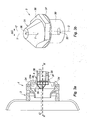
- FIG. 3a Another exemplary embodiment is illustrated with an off-center position of the injection head 31 relative to the body 30 and the mounting nut 35 is highlighted. It then appears that the axis C'C of the fuel flow channel 36, which passes through the head 31, is parallel and offset with respect to the axis of the conduit 32 of the injector body 30, coinciding with the axis X'X of whirlpool 2.
- the axis offset is thus obtained by the position of the injection head 31 relative to the body of the injector 30, while the guide flange 23a is centered in the radial groove 24.
- the perspective view of the figure 3b highlights the asymmetrical embodiment of the fastening of the injection head 31 on the mounting nut 35 of the head on the body 30.
- the body 30 terminates in a circular flange 37 on which the nut 35 is mounted by internal screwing.
- On the figure 3b also appears the offset ⁇ C of the axis T'T of the channel 36 of the injection head 31 and the axis C'C of the duct 32.
- the invention is not limited to the embodiments described and shown.
- it is possible to use different types of swirler for example swirlers with several crowns of contra-rotating cells, or injectors with pyramidal head or concave profile.
- the invention naturally applies to single-venturi swirlers, that is to say which are not equipped with a second venturi 20b associated with the air flow F1.
- the guide ferrule and an off-centered injection head it is possible to accumulate a non-axisymmetric positioning of the guide ferrule and an off-centered injection head, for example by combining the embodiments of the figures 2 and 3a / 3b .
- the whirlpool may not be fixed on the wall of the combustion chamber but, for example on the housing.
- the guide means of the injector in the whirlpool can be constituted by any known means, for example adjustable bearings, bushings, spacers, etc.
Landscapes
- Engineering & Computer Science (AREA)
- Chemical & Material Sciences (AREA)
- Combustion & Propulsion (AREA)
- Mechanical Engineering (AREA)
- General Engineering & Computer Science (AREA)
- Fuel-Injection Apparatus (AREA)
- Combustion Methods Of Internal-Combustion Engines (AREA)
Description
- L'invention concerne un procédé d'injection de carburant dans une chambre de combustion d'une turbine à gaz - turbomoteur, turboréacteur ou groupe auxiliaire de puissance (GAP) - afin de supprimer ou, du moins limiter, les instabilités de combustions. L'invention se rapporte également à un système d'injection pour sa mise en oeuvre.
- Dans une chambre de combustion de turbine à gaz, tel qu'un turbomoteur, des injecteurs montés sur un carter fournissent du carburant qui est mélangé à de l'air à l'intérieur de mélangeurs air/carburant, communément appelés tourbillonneurs, répartis sur le fond de la chambre de combustion. L'air provient du dernier étage d'un compresseur de la turbine à gaz dont une partie est introduite dans la chambre de combustion par ce tourbillonneur. Le carburant est introduit dans l'injecteur par un orifice, formé à l'extrémité d'une tubulure. L'air et le carburant sont mélangés dans les tourbillonneurs puis brûlés dans la chambre pour générer des gaz. L'énergie thermique de ces gaz est convertie en travail mécanique par l'intermédiaire de turbines et/ou en poussée via la tuyère, permettant ainsi d'assurer la propulsion de l'aéronef ou la fourniture de puissance mécanique pour une installation terrestre ou marine.
- Lors de la conception d'un turbomoteur et en particulier de sa chambre de combustion, un risque important, qui ne peut être levé avant la première rotation du moteur, est la présence d'instabilités de combustion au sein de la chambre dans la plage de fonctionnement du moteur. Ces instabilités sont produites lorsque les fluctuations de combustion dans la chambre entrent en résonance avec des phénomènes physiques localisés dans celle-ci (mode propre de vibration acoustique, de vibration mécanique, instabilité d'alimentation en carburant, etc.). Ces instabilités génèrent alors des vibrations dites asynchrones car elles ne sont pas directement liées à la vitesse de rotation du moteur. Lorsqu'il y a résonnance entre un mode propre acoustique et les fluctuations de dégagement de chaleur lié à la combustion, on parle communément de couplage thermo-acoustique provoquant des instabilités de combustion.
- Plus globalement, les instabilités de combustion peuvent induire des vibrations potentiellement destructrices de la structure de la chambre, voire du moteur, empêchant la certification du moteur.
- Lorsque la présence d'instabilités de combustion est avérée, une solution classique consiste à redessiner la chambre de combustion et/ou les systèmes d'injection en fonction des impacts. Cette solution est coûteuse et induit des retards importants de réalisation et donc de certification.
- Il est connu du document de brevet
US 4 831 700 des moyens de lutte contre l'instabilité de combustion d'une turbine comportant une valve annulaire montée sur un épaulement de l'injecteur. Une chambre d'air interne est ainsi créée. La valve présente une tête en avancée pour contrôler le flux de carburant à partir d'un orifice formé dans l'épaulement de l'injecteur, à proximité de la sortie de carburant. Une telle architecture est complexe et repose sur une variation d'ouverture de cette valve, ce qui peut supprimer les interruptions ou les impulsions de flux de carburant. Cependant, si de tels moyens réduisent l'instabilité de combustion liée aux irrégularités de flux de carburant ils ne permettent pas de résoudre ce problème d'instabilités de combustion. - Il est par ailleurs connu du document de brevet
EP 1 413 830 , une configuration basée sur un diviseur d'air à extrémité conique, localisé entre l'injecteur de carburant et le tourbillonneur d'air. Le diviseur sépare le flux d'air en deux courants concentriques pour créer dans la chambre une zone de recirculation à deux voies. Pour les mêmes raisons que ci-dessus, cette solution ne supprime pas les instabilités de combustion. Les caractéristiques du préambule de la revendication 3 sont connues du documentEP 1 801 503 A2 . - L'invention vise à réduire, voire supprimer, les instabilités de combustion, en proposant d'injecter le carburant selon un axe particulier induisant un écoulement du carburant dans le tourbillonneur qui n'est plus parfaitement à symétrie cyclique.
- Plus précisément, la présente invention a pour objet un procédé d'injection de carburant dans une chambre de combustion de turbine à gaz, par un système mélangeur air/carburant selon la revendication 1. Dans ce procédé, l'injection de carburant est effectuée dans le système mélangeur selon un axe parallèle à l'axe central de ce système au sens strict, c'est-à-dire distinct de cet axe. Il est alors dit que l'axe d'injection est décentré par rapport à l'axe du mélangeur. Dans ces conditions, en absence de projection de carburant axisymétrique, la flamme de combustion n'entre plus en résonance, éliminant ou réduisant les instabilités de combustion à un niveau acceptable.
- Selon des modes de réalisation particuliers :
- la chambre de combustion, agencée dans un carter, est angulairement décalée par rapport au carter, l'injection de carburant étant effectuée par un injecteur solidaire du carter et le système mélangeur étant solidaire de la chambre de combustion ; et/ou
- l'injection est décentrée dans le système mélangeur : ce mode est en particulier mis en oeuvre lorsque le système mélangeur possède un ou plusieurs degrés de liberté sur la chambre de combustion.
- L'invention se rapporte également à un système mélangeur air/carburant comprenant une chambre de combustion de turbine à gaz et un carter de protection de la chambre selon la revendication 3, ce système étant apte à mettre en oeuvre le procédé ci-dessus. Ce système comporte au moins un tourbillonneur d'entrée d'air comprimé, le tourbillonneur présentant un axe de symétrie centrale, et un injecteur de carburant équipé d'une tête d'injection, présentant un axe de symétrie propre. Chaque injecteur est monté dans le tourbillonneur correspondant à l'aide de moyens de guidage, en particulier une virole à collerette montée dans une bague de retenue solidaire du tourbillohneur, de sorte que l'axe de symétrie de la tête d'injection est décentré par rapport à l'axe de symétrie centrale du tourbillonneur.
- Selon des modes de réalisation particuliers :
- des moyens rendent les tourbillonneurs solidaires de la chambre et les injecteurs solidaires du carter, et des moyens de fixation à excentrement de la chambre sur le carter sont aptes à décaler angulairement la chambre par rapport au carter de sorte que les injecteurs sont décalés axialement par rapport aux tourbillonneurs correspondants ;
- chaque injecteur présente un axe principal de symétrie et une tête d'injection ayant un canal central de circulation de carburant d'axe décentré par rapport à l'axe principal du tourbillonneur ;
- la tête d'injection, avantageusement tronconique, peut être montée décentrée par rapport à un corps principal de l'injecteur, l'axe du canal de la tête étant l'axe de symétrie de la tête d'injection.
- D'autres caractéristiques et avantages de la présente invention apparaîtront à la lecture de l'exemple détaillé de réalisation qui suit, en référence aux figures annexées qui représentent, respectivement :
- la
figure 1 , une vue en coupe d'un premier exemple de système mélangeur selon l'invention présentant un injecteur d'axe parallèle et décalé par rapport à l'axe du tourbillonneur associé ; - la
figure 2 , une vue schématique de la chambre de combustion protégée par un carter et présentant des moyens de fixation excentriques sur le carter aptes à décaler angulairement la chambre du carter, afin d'obtenir le décalage d'axe selon lafigure 1 ; et - les
figures 3a et 3b , des vues en coupe et en perspective d'un autre exemple d'injecteur de carburant excentré, respectivement dans le tourbillonneur et hors de ce système. - Les termes « amont » et « aval » ou équivalents désignent des parties d'élément en référence à l'écoulement du carburant dans l'injecteur selon l'axe C'C.
- En référence à la vue en coupe de la
figure 1 , un exemple de mélangeur 2 selon l'invention communément appelé tourbillonneur muni d'alvéoles d'entrée d'air 21, et d'une bague de retenue 22. Cette bague permet de loger une virole de guidage 23 à collerette 23a pour un injecteur de carburant 3. Le tourbillonneur 2 est rendu solidaire de la chambre de combustion 4 à travers un tube à flamme 5. L'injecteur 3 est fixé sur le carter 6, qui enveloppe la chambre de combustion 4. - Les alvéoles d'entrée d'air 21 sont formées dans une pièce annulaire 2a qui vient s'emboîter coaxialement, selon l'axe X'X du tourbillonneur 2 et du système mélangeur 1, sur une deuxième pièce annulaire 2b. La première pièce 2a forme, à l'intérieur du tourbillonneur 2, une paroi venturi 20a et la deuxième pièce 2b une autre paroi venturi 20b. La première paroi venturi 20a pénètre la deuxième 20b de sorte à créer un espace inter-venturi E1 dans lequel circule un flux d'air F1 provenant des alvéoles 21. Ce flux forme en sortie un cône d'air C1 qui vient envelopper le cône de mélange air/carburant C2 formé par l'espace venturi interne E2 limité par la première paroi venturi 20a.
- Dans cet espace E2, le flux d'air interne F2 issu des alvéoles 21 est mélangé au carburant fourni par l'injecteur 3. Plus précisément, les tourbillons d'air forment dans le venturi interne E2 des nappes d'air qui vont se chevaucher à l'entrée de la chambre de combustion 4. Dans chaque nappe, les particules d'air viennent se mixer de manière fluide et uniforme aux particules de carburant projetées par l'injecteur 3, ce qui réalise un mélange air/carburant performant.
- Les flux d'air interne F1 et F2 peuvent avantageusement présenter indépendamment un écoulement tourbillonnant ou non, dans le même sens ou en sens contraire, de manière à obtenir une pulvérisation du carburation et/ou un mélange air/carburant le plus efficace possible, conforme aux exigences de performances de la chambre de combustion.
- Dans l'exemple illustré, l'injecteur de carburant 3 présente un corps principal 30 cylindrique comportant une tête d'injection tronconique 31. Un conduit 32 d'amenée de carburant d'axe C'C confondu avec l'axe de symétrie de l'injecteur traverse le corps cylindrique 30 et la tête d'injection 31. Dans cet exemple de réalisation, la tête d'injection 31 présente un canal d'injection 36 dans le prolongement du conduit 32 du corps d'injecteur 30.
- Le montage de l'injecteur dans le tourbillonneur 2 est réalisé via la virole de guidage 23 dont la collerette 23a vient s'insérer dans une gorge radiale 24, formée entre la bague de retenue 22 et la paroi aval P2 de la première pièce annulaire 2a. La bague 22 est solidarisée, par exemple brasée à la paroi P2, pour former le fond 4a de la gorge 24.
- La collerette 23a est positionnée de manière non axisymétrique dans la gorge 24 de sorte que, en mode d'utilisation à chaud - les parties de gorge non occupées 24a et 24b ne sont pas de même profondeur - si bien que l'injecteur 3 est lui-même positionné de façon non axisymétrique par rapport au tourbillonneur 2. L'écoulement du carburant n'est plus parfaitement axisymétrique car si les axes C'C et X'X, respectivement de l'injecteur 3 et du tourbillonneur 2, restent parallèles ils ne sont pas confondus. Ils présentent donc un écart ΔC d'environ 1 mm dans l'exemple illustré. Cet écart dépend des dimensions du moteur.
- Dans ces conditions, en absence de projection axisymétrique de carburant, la flamme de combustion n'entre plus en résonance : les instabilités de combustion sont éliminées ou réduites à un niveau acceptable.
- Dans le cas où le tourbillonneur est solidaire du fond de chambre, ce montage non axisymétrique peut être réalisé par un décalage excentré des fixations de la chambre 4 sur le carter 6 par rapport à une position de référence en alignement nominale. Dans l'exemple de montage schématique illustré par la vue en perspective de la
figure 2 , des brides excentriques 10 de fixation de la chambre 4 sur le carter 6 sont utilisées. Ces brides excentriques 10 permettent de décaler angulairement la chambre selon un décalage ΔA d'environ quelques dixièmes de degrés, la valeur précise dépendant des dimensions du moteur par rapport à une position nominale de référence. - Un tel décalage induit un décalage équivalent des tourbillonneurs 2, solidaires de la chambre 4, et des injecteurs 3, solidaires du carter 6. Il s'ensuit que l'axe d'écoulement du carburant C'C des injecteurs 3 présente l'écart ΔC par rapport à l'axe X'X des tourbillonneurs 2, conforme à la
figure 1 . - Dans un autre exemple illustré par les
figures 3a et 3b , le montage non axisymétrique d'un injecteur 3 dans un tourbillonneur 2 (figure 1 ), peut encore être réalisé par la position décentrée de la tête d'injection 31 par rapport au corps principal 30 de l'injecteur 3. - Cette solution est particulièrement bien adaptée lorsque le tourbillonneur n'est pas directement solidaire de la chambre de combustion. En particulier, dans le cas où la virole de guidage 23, garantissant des degrés de liberté entre le tourbillonneur et l'injecteur, est déportée à l'interface entre le tourbillonneur 2 et la chambre 4, la position relative de l'axe C'C de l'injecteur de carburant 3 et XX' du tourbillonneur 2 est déterminée par la position de l'axe de la virole de guidage 23, solidaire du tourbillonneur 2.
- En référence à la
figure 3a , un autre exemple de réalisation est illustré avec une position décentrée de la tête d'injection 31 par rapport au corps 30 et à l'écrou de montage 35 est mise en évidence. Il apparaît alors que l'axe C'C du canal 36 d'écoulement de carburant, qui traverse la tête 31, est parallèle et décalé par rapport à l'axe du conduit 32 du corps d'injecteur 30, confondu avec l'axe X'X du tourbillonneur 2. - Le décalage d'axe est ainsi obtenu par la position de la tête d'injection 31 par rapport au corps de l'injecteur 30, alors que la collerette de guidage 23a est centrée dans la gorge radiale 24.
- La vue en perspective de la
figure 3b met en évidence la réalisation asymétrique de la solidarisation de la tête d'injection 31 sur l'écrou de montage 35 de la tête sur le corps 30. Le corps 30 se termine par un flasque circulaire 37 sur lequel est monté l'écrou 35 par vissage interne. Sur lafigure 3b , apparaît également le décalage ΔC de l'axe T'T du canal 36 de la tête d'injection 31 et de l'axe C'C du conduit 32. - L'invention n'est pas limitée aux exemples de réalisation décrits et représentés. Il est par exemple possible d'utiliser différents types de tourbillonneur, par exemple des tourbillonneurs à plusieurs couronnes d'alvéoles en contra-rotation, ou des injecteurs à tête pyramidale ou à profil concave. L'invention s'applique bien entendu aux tourbillonneurs mono-venturi, c'est-à-dire qui ne sont pas équipés de deuxième venturi 20b associé au flux d'air F1.
- Selon l'invention, il est possible de cumuler un positionnement non axisymétrique de la virole de guidage et une tête d'injection décentrée, par exemple en combinant les réalisations des
figures 2 et3a/3b . De plus, selon un autre exemple de réalisation, il est possible de fixer par brasure la bague 22 de manière excentrée de sorte que, en utilisation, la virole 23 vienne se centrer dans la bague et donc de manière non axisymétrique par rapport à l'axe du tourbillonneur. Par ailleurs, le tourbillonneur peut ne pas être fixé sur la paroi de la chambre de combustions mais, par exemple sur le carter. De plus, les moyens de guidage de l'injecteur dans le tourbillonneur peuvent être constitués par tout moyen connu, par exemple des paliers réglables, des douilles, des entretoises, etc.
Claims (7)
- Procédé d'injection de carburant par un système mélangeur air/carburant (1) présentant un axe géométrique de symétrie centrale (X'X), dans une chambre de combustion (4) de turbine à gaz, l'injection de carburant étant effectuée dans le système mélangeur (1) selon un axe (C'C) parallèle à l'axe de symétrie (X'X) de ce système (1) et distinct de cet axe (X'X), caractérisé en ce que la chambre de combustion (4), agencée dans un carter (6), est angulairement décalée (ΔA) par rapport au carter (6), l'injection de carburant étant effectuée par un injecteur (3) solidaire du carter (6) et le système mélangeur (1) étant solidaire de la chambre de combustion (4).
- Procédé d'injection selon la revendication 1, dans lequel l'injection est décentrée (ΔC) dans le système mélangeur (1), en particulier lorsque le système mélangeur possède au moins un degré de liberté sur la chambre de combustion.
- Système mélangeur air/carburant comprenant une chambre de combustion de turbine à gaz et un carter de protection de la chambre, apte à mettre en oeuvre le procédé d'injection selon l'une quelconque des revendications précédentes, comportant au moins un tourbillonneur d'entrée d'air comprimé (2), le tourbillonneur (2) présentant un axe de symétrie central (X'X), et un injecteur de carburant (3) équipé d'une tête d'injection (31) présentant un axe de symétrie propre (T'T), et dans lequel chaque injecteur (3) est monté dans le tourbillonneur (2) correspondant à l'aide de moyens de guidage (23, 22) de sorte que l'axe de symétrie (T'T) de la tête d'injection (31) est décentré par rapport à l'axe de symétrie centrale (X'X) du tourbillonneur (2), caractérisé en ce que des moyens de fixation à excentrement (10) de la chambre (4) sur le carter (6) sont aptes à décaler angulairement (ΔA) la chambre (4) par rapport au carter (6) de sorte que les injecteurs (3) sont décalés axialement (ΔC) par rapport aux tourbillonneurs correspondants (2).
- Système mélangeur selon la revendication précédente, dans lequel les moyens de guidage comportent une virole (23) à collerette (23a) montée dans une bague de retenue (22) solidaire du tourbillonnneur (2).
- Système mélangeur selon l'une des revendications 3 ou 4, dans lequel des moyens (5, 35) rendent les tourbillonneurs (2) solidaires de la chambre (4) et les injecteurs (3) solidaires du carter (6).
- Système mélangeur selon l'une quelconque des revendications 3 à 5, dans lequel chaque injecteur (3) présente un axe principal de symétrie et une tête d'injection (31) ayant un canal central (36) de circulation de carburant d'axe (T'T) décentré par rapport à l'axe principal (X'X) du système d'injection (1).
- Système mélangeur selon la revendication précédente, dans lequel la tête d'injection (31) est montée décentrée par rapport à un corps principal de l'injecteur (30), l'axe (T'T) du canal (36) de la tête étant l'axe de symétrie de la tête d'injection (31).
Priority Applications (1)
| Application Number | Priority Date | Filing Date | Title |
|---|---|---|---|
| PL12734965T PL2721347T3 (pl) | 2011-06-20 | 2012-06-19 | Sposób wtryskiwania paliwa do komory spalania turbiny gazowej oraz układ wtryskowy do realizacji tego sposobu |
Applications Claiming Priority (2)
| Application Number | Priority Date | Filing Date | Title |
|---|---|---|---|
| FR1155371A FR2976649B1 (fr) | 2011-06-20 | 2011-06-20 | Procede d'injection de carburant dans une chambre de combustion d'une turbine a gaz et systeme d'injection pour sa mise en oeuvre |
| PCT/FR2012/051368 WO2012175856A1 (fr) | 2011-06-20 | 2012-06-19 | Procédé d'injection de carburant dans une chambre de combustion d'une turbine à gaz et système d'injection pour sa mise en oeuvre |
Publications (2)
| Publication Number | Publication Date |
|---|---|
| EP2721347A1 EP2721347A1 (fr) | 2014-04-23 |
| EP2721347B1 true EP2721347B1 (fr) | 2015-08-05 |
Family
ID=46508081
Family Applications (1)
| Application Number | Title | Priority Date | Filing Date |
|---|---|---|---|
| EP12734965.2A Active EP2721347B1 (fr) | 2011-06-20 | 2012-06-19 | Procédé d'injection de carburant dans une chambre de combustion d'une turbine à gaz et système d'injection pour sa mise en oeuvre |
Country Status (11)
| Country | Link |
|---|---|
| US (1) | US9677505B2 (fr) |
| EP (1) | EP2721347B1 (fr) |
| JP (1) | JP6030128B2 (fr) |
| KR (1) | KR101907722B1 (fr) |
| CN (1) | CN103608625B (fr) |
| CA (1) | CA2839967C (fr) |
| ES (1) | ES2546605T3 (fr) |
| FR (1) | FR2976649B1 (fr) |
| PL (1) | PL2721347T3 (fr) |
| RU (1) | RU2598502C2 (fr) |
| WO (1) | WO2012175856A1 (fr) |
Families Citing this family (6)
| Publication number | Priority date | Publication date | Assignee | Title |
|---|---|---|---|---|
| US10731862B2 (en) * | 2015-08-26 | 2020-08-04 | General Electric Company | Systems and methods for a multi-fuel premixing nozzle with integral liquid injectors/evaporators |
| CN109631084B (zh) * | 2018-12-13 | 2020-11-06 | 西安航天动力研究所 | 冲压发动机燃烧室稳定器及稳焰方法 |
| FR3105984B1 (fr) * | 2020-01-03 | 2023-07-14 | Safran Aircraft Engines | Système d’injection de carburant antirotatif |
| US11686474B2 (en) | 2021-03-04 | 2023-06-27 | General Electric Company | Damper for swirl-cup combustors |
| CA3217742A1 (fr) * | 2021-05-12 | 2022-11-17 | Egidio PUCCI | Injecteur de carburant et gicleur de carburant pour une turbine a gaz, et moteur a turbine a gaz comprenant le gicleur |
| JP2025500601A (ja) | 2022-02-03 | 2025-01-09 | ヌオーヴォ・ピニォーネ・テクノロジー・ソチエタ・レスポンサビリタ・リミタータ | ガスタービン用燃料ノズル、燃料ノズルを備えた燃焼器、及びガスタービン |
Family Cites Families (23)
| Publication number | Priority date | Publication date | Assignee | Title |
|---|---|---|---|---|
| US4201047A (en) * | 1976-06-10 | 1980-05-06 | Morgan J Randolph | Low emission combustors |
| US4111369A (en) * | 1977-07-05 | 1978-09-05 | General Motors Corporation | Fuel nozzle |
| US4454711A (en) * | 1981-10-29 | 1984-06-19 | Avco Corporation | Self-aligning fuel nozzle assembly |
| US4831700A (en) | 1986-07-24 | 1989-05-23 | Ex-Cell-O Corporation | Method for making a fuel injector |
| US5265411A (en) * | 1992-10-05 | 1993-11-30 | United Technologies Corporation | Attachment clip |
| US5267442A (en) * | 1992-11-17 | 1993-12-07 | United Technologies Corporation | Fuel nozzle with eccentric primary circuit orifice |
| RU2122684C1 (ru) * | 1994-09-29 | 1998-11-27 | Акционерное общество открытого типа "Экотеплогаз" | Способ сжигания органического топлива в камере сгорания газотурбинных установок и других топливных устройствах |
| JP3413101B2 (ja) * | 1998-06-18 | 2003-06-03 | 佐藤工業株式会社 | 外殻PCa柱部材製造のための外型枠装置 |
| US6272842B1 (en) * | 1999-02-16 | 2001-08-14 | General Electric Company | Combustor tuning |
| RU2170391C1 (ru) * | 2000-03-20 | 2001-07-10 | Открытое Акционерное Общество "Турбомоторный Завод" | Горелочное устройство камер сгорания |
| GB0019533D0 (en) * | 2000-08-10 | 2000-09-27 | Rolls Royce Plc | A combustion chamber |
| JP3960166B2 (ja) * | 2001-08-29 | 2007-08-15 | 株式会社日立製作所 | ガスタービン燃焼器およびガスタービン燃焼器の運転方法 |
| US6813889B2 (en) * | 2001-08-29 | 2004-11-09 | Hitachi, Ltd. | Gas turbine combustor and operating method thereof |
| US6625971B2 (en) * | 2001-09-14 | 2003-09-30 | United Technologies Corporation | Fuel nozzle producing skewed spray pattern |
| US6581386B2 (en) * | 2001-09-29 | 2003-06-24 | General Electric Company | Threaded combustor baffle |
| US6986255B2 (en) | 2002-10-24 | 2006-01-17 | Rolls-Royce Plc | Piloted airblast lean direct fuel injector with modified air splitter |
| US7836699B2 (en) * | 2005-12-20 | 2010-11-23 | United Technologies Corporation | Combustor nozzle |
| FR2903171B1 (fr) * | 2006-06-29 | 2008-10-17 | Snecma Sa | Agencement a liaison par crabot pour chambre de combustion de turbomachine |
| GB2454247A (en) * | 2007-11-02 | 2009-05-06 | Siemens Ag | A Combustor for a Gas-Turbine Engine Has a Burner Head with Fuel Delivered at a Compound Angle |
| WO2009068424A1 (fr) * | 2007-11-27 | 2009-06-04 | Alstom Technology Ltd | Procédé et dispositif pour la combustion d'hydrogène dans un brûleur à prémélange |
| US8047008B2 (en) * | 2008-03-31 | 2011-11-01 | General Electric Company | Replaceable orifice for combustion tuning and related method |
| FR2948749B1 (fr) * | 2009-07-29 | 2011-09-09 | Snecma | Systeme d'injection de carburant pour une chambre de combustion de turbomachine |
| FI124346B (fi) * | 2011-11-25 | 2014-07-15 | Rmv Tech Oy | Polttokammio |
-
2011
- 2011-06-20 FR FR1155371A patent/FR2976649B1/fr not_active Expired - Fee Related
-
2012
- 2012-06-19 US US14/126,672 patent/US9677505B2/en active Active
- 2012-06-19 EP EP12734965.2A patent/EP2721347B1/fr active Active
- 2012-06-19 ES ES12734965.2T patent/ES2546605T3/es active Active
- 2012-06-19 KR KR1020147000577A patent/KR101907722B1/ko not_active Expired - Fee Related
- 2012-06-19 CN CN201280030093.1A patent/CN103608625B/zh active Active
- 2012-06-19 JP JP2014516416A patent/JP6030128B2/ja not_active Expired - Fee Related
- 2012-06-19 PL PL12734965T patent/PL2721347T3/pl unknown
- 2012-06-19 RU RU2014100109/06A patent/RU2598502C2/ru active
- 2012-06-19 CA CA2839967A patent/CA2839967C/fr not_active Expired - Fee Related
- 2012-06-19 WO PCT/FR2012/051368 patent/WO2012175856A1/fr not_active Ceased
Also Published As
| Publication number | Publication date |
|---|---|
| CA2839967A1 (fr) | 2012-12-27 |
| CN103608625B (zh) | 2015-07-22 |
| WO2012175856A1 (fr) | 2012-12-27 |
| RU2014100109A (ru) | 2015-07-27 |
| KR20140038515A (ko) | 2014-03-28 |
| KR101907722B1 (ko) | 2018-10-12 |
| ES2546605T3 (es) | 2015-09-25 |
| US20140116384A1 (en) | 2014-05-01 |
| FR2976649A1 (fr) | 2012-12-21 |
| PL2721347T3 (pl) | 2015-11-30 |
| EP2721347A1 (fr) | 2014-04-23 |
| FR2976649B1 (fr) | 2015-01-23 |
| CN103608625A (zh) | 2014-02-26 |
| US9677505B2 (en) | 2017-06-13 |
| CA2839967C (fr) | 2019-08-27 |
| JP6030128B2 (ja) | 2016-11-24 |
| RU2598502C2 (ru) | 2016-09-27 |
| JP2014517250A (ja) | 2014-07-17 |
Similar Documents
| Publication | Publication Date | Title |
|---|---|---|
| CA2646959C (fr) | Systeme d'injection d'un melange d'air et de carburant dans une chambre de combustion de turbomachine | |
| EP1806535B1 (fr) | Système d'injection multimode pour chambre de combustion, notamment d'un turboréacteur | |
| EP1857741B1 (fr) | Chambre de combustion d'une turbomachine | |
| CA2593186C (fr) | Dispositif d'injection d'un melange d'air et de carburant, chambre de combustion et turbomachine munies d'un tel dispositif | |
| EP2815183B1 (fr) | Dispositif d'injection d'air et de carburant pour une chambre de combustion d'une turbomachine | |
| WO2010081940A1 (fr) | Dispositif d'injection d'un mélange d'air et de carburant dans une chambre de combustion de turbomachine | |
| CA2839967C (fr) | Procede d'injection de carburant dans une chambre de combustion de turbine a gaz et systeme d'injection pour sa mise en oeuvre | |
| EP2488792B1 (fr) | Injecteur multi-point pour une chambre de combustion de turbomachine | |
| EP1873456B1 (fr) | Dispositif d'injection d'un mélange d'air et de carburant, chambre de combustion et turbomachine munies d'un tel dispositif | |
| EP1923636B1 (fr) | Dispositif d'injection d'un mélange d'air et de carburant, chambre de combustion et turbomachine munies d'un tel dispositif | |
| FR3020865A1 (fr) | Chambre annulaire de combustion | |
| FR2975467A1 (fr) | Systeme d'injection de carburant pour une chambre de combustion de turbomachine | |
| EP3286500B1 (fr) | Chambre de combustion de turbomachine comportant un dispositif de guidage de flux d'air de forme spécifique | |
| WO2012104523A2 (fr) | Dispositif d'injection pour une chambre de combustion de turbomachine | |
| FR3042588A1 (fr) | Dispositif d'injection pour une chambre de combustion d'une turbomachine | |
| WO2025168900A1 (fr) | Système d'injection d'hydrogène et d'air | |
| FR2975466A1 (fr) | Chambre annulaire de combustion pour une turbomachine | |
| FR3144858A1 (fr) | Système d’injection de carburant pour turbomachine | |
| FR3165040A1 (fr) | Dispositif d'injection de carburant | |
| FR2943762A1 (fr) | Systeme d'injection de carburant dans une chambre de combustion de turbomachine |
Legal Events
| Date | Code | Title | Description |
|---|---|---|---|
| PUAI | Public reference made under article 153(3) epc to a published international application that has entered the european phase |
Free format text: ORIGINAL CODE: 0009012 |
|
| 17P | Request for examination filed |
Effective date: 20131223 |
|
| AK | Designated contracting states |
Kind code of ref document: A1 Designated state(s): AL AT BE BG CH CY CZ DE DK EE ES FI FR GB GR HR HU IE IS IT LI LT LU LV MC MK MT NL NO PL PT RO RS SE SI SK SM TR |
|
| DAX | Request for extension of the european patent (deleted) | ||
| REG | Reference to a national code |
Ref country code: DE Ref legal event code: R079 Ref document number: 602012009367 Country of ref document: DE Free format text: PREVIOUS MAIN CLASS: F23R0003140000 Ipc: F23M0020000000 |
|
| GRAP | Despatch of communication of intention to grant a patent |
Free format text: ORIGINAL CODE: EPIDOSNIGR1 |
|
| RIC1 | Information provided on ipc code assigned before grant |
Ipc: F23M 20/00 20140101AFI20150121BHEP |
|
| INTG | Intention to grant announced |
Effective date: 20150212 |
|
| GRAS | Grant fee paid |
Free format text: ORIGINAL CODE: EPIDOSNIGR3 |
|
| GRAA | (expected) grant |
Free format text: ORIGINAL CODE: 0009210 |
|
| AK | Designated contracting states |
Kind code of ref document: B1 Designated state(s): AL AT BE BG CH CY CZ DE DK EE ES FI FR GB GR HR HU IE IS IT LI LT LU LV MC MK MT NL NO PL PT RO RS SE SI SK SM TR |
|
| REG | Reference to a national code |
Ref country code: GB Ref legal event code: FG4D Free format text: NOT ENGLISH |
|
| REG | Reference to a national code |
Ref country code: CH Ref legal event code: EP |
|
| REG | Reference to a national code |
Ref country code: AT Ref legal event code: REF Ref document number: 740931 Country of ref document: AT Kind code of ref document: T Effective date: 20150815 |
|
| REG | Reference to a national code |
Ref country code: IE Ref legal event code: FG4D Free format text: LANGUAGE OF EP DOCUMENT: FRENCH |
|
| REG | Reference to a national code |
Ref country code: DE Ref legal event code: R096 Ref document number: 602012009367 Country of ref document: DE |
|
| REG | Reference to a national code |
Ref country code: ES Ref legal event code: FG2A Ref document number: 2546605 Country of ref document: ES Kind code of ref document: T3 Effective date: 20150925 |
|
| REG | Reference to a national code |
Ref country code: SE Ref legal event code: TRGR |
|
| REG | Reference to a national code |
Ref country code: PL Ref legal event code: T3 |
|
| REG | Reference to a national code |
Ref country code: AT Ref legal event code: MK05 Ref document number: 740931 Country of ref document: AT Kind code of ref document: T Effective date: 20150805 |
|
| REG | Reference to a national code |
Ref country code: LT Ref legal event code: MG4D |
|
| REG | Reference to a national code |
Ref country code: NL Ref legal event code: MP Effective date: 20150805 |
|
| PG25 | Lapsed in a contracting state [announced via postgrant information from national office to epo] |
Ref country code: LV Free format text: LAPSE BECAUSE OF FAILURE TO SUBMIT A TRANSLATION OF THE DESCRIPTION OR TO PAY THE FEE WITHIN THE PRESCRIBED TIME-LIMIT Effective date: 20150805 Ref country code: FI Free format text: LAPSE BECAUSE OF FAILURE TO SUBMIT A TRANSLATION OF THE DESCRIPTION OR TO PAY THE FEE WITHIN THE PRESCRIBED TIME-LIMIT Effective date: 20150805 Ref country code: LT Free format text: LAPSE BECAUSE OF FAILURE TO SUBMIT A TRANSLATION OF THE DESCRIPTION OR TO PAY THE FEE WITHIN THE PRESCRIBED TIME-LIMIT Effective date: 20150805 Ref country code: GR Free format text: LAPSE BECAUSE OF FAILURE TO SUBMIT A TRANSLATION OF THE DESCRIPTION OR TO PAY THE FEE WITHIN THE PRESCRIBED TIME-LIMIT Effective date: 20151106 Ref country code: NO Free format text: LAPSE BECAUSE OF FAILURE TO SUBMIT A TRANSLATION OF THE DESCRIPTION OR TO PAY THE FEE WITHIN THE PRESCRIBED TIME-LIMIT Effective date: 20151105 |
|
| PG25 | Lapsed in a contracting state [announced via postgrant information from national office to epo] |
Ref country code: PT Free format text: LAPSE BECAUSE OF FAILURE TO SUBMIT A TRANSLATION OF THE DESCRIPTION OR TO PAY THE FEE WITHIN THE PRESCRIBED TIME-LIMIT Effective date: 20151207 Ref country code: IS Free format text: LAPSE BECAUSE OF FAILURE TO SUBMIT A TRANSLATION OF THE DESCRIPTION OR TO PAY THE FEE WITHIN THE PRESCRIBED TIME-LIMIT Effective date: 20151205 Ref country code: HR Free format text: LAPSE BECAUSE OF FAILURE TO SUBMIT A TRANSLATION OF THE DESCRIPTION OR TO PAY THE FEE WITHIN THE PRESCRIBED TIME-LIMIT Effective date: 20150805 Ref country code: AT Free format text: LAPSE BECAUSE OF FAILURE TO SUBMIT A TRANSLATION OF THE DESCRIPTION OR TO PAY THE FEE WITHIN THE PRESCRIBED TIME-LIMIT Effective date: 20150805 Ref country code: RS Free format text: LAPSE BECAUSE OF FAILURE TO SUBMIT A TRANSLATION OF THE DESCRIPTION OR TO PAY THE FEE WITHIN THE PRESCRIBED TIME-LIMIT Effective date: 20150805 |
|
| PG25 | Lapsed in a contracting state [announced via postgrant information from national office to epo] |
Ref country code: NL Free format text: LAPSE BECAUSE OF FAILURE TO SUBMIT A TRANSLATION OF THE DESCRIPTION OR TO PAY THE FEE WITHIN THE PRESCRIBED TIME-LIMIT Effective date: 20150805 |
|
| PG25 | Lapsed in a contracting state [announced via postgrant information from national office to epo] |
Ref country code: EE Free format text: LAPSE BECAUSE OF FAILURE TO SUBMIT A TRANSLATION OF THE DESCRIPTION OR TO PAY THE FEE WITHIN THE PRESCRIBED TIME-LIMIT Effective date: 20150805 Ref country code: SK Free format text: LAPSE BECAUSE OF FAILURE TO SUBMIT A TRANSLATION OF THE DESCRIPTION OR TO PAY THE FEE WITHIN THE PRESCRIBED TIME-LIMIT Effective date: 20150805 Ref country code: DK Free format text: LAPSE BECAUSE OF FAILURE TO SUBMIT A TRANSLATION OF THE DESCRIPTION OR TO PAY THE FEE WITHIN THE PRESCRIBED TIME-LIMIT Effective date: 20150805 Ref country code: CZ Free format text: LAPSE BECAUSE OF FAILURE TO SUBMIT A TRANSLATION OF THE DESCRIPTION OR TO PAY THE FEE WITHIN THE PRESCRIBED TIME-LIMIT Effective date: 20150805 |
|
| REG | Reference to a national code |
Ref country code: DE Ref legal event code: R097 Ref document number: 602012009367 Country of ref document: DE |
|
| PG25 | Lapsed in a contracting state [announced via postgrant information from national office to epo] |
Ref country code: RO Free format text: LAPSE BECAUSE OF FAILURE TO SUBMIT A TRANSLATION OF THE DESCRIPTION OR TO PAY THE FEE WITHIN THE PRESCRIBED TIME-LIMIT Effective date: 20150805 |
|
| PLBE | No opposition filed within time limit |
Free format text: ORIGINAL CODE: 0009261 |
|
| REG | Reference to a national code |
Ref country code: FR Ref legal event code: PLFP Year of fee payment: 5 |
|
| STAA | Information on the status of an ep patent application or granted ep patent |
Free format text: STATUS: NO OPPOSITION FILED WITHIN TIME LIMIT |
|
| 26N | No opposition filed |
Effective date: 20160509 |
|
| PG25 | Lapsed in a contracting state [announced via postgrant information from national office to epo] |
Ref country code: SI Free format text: LAPSE BECAUSE OF FAILURE TO SUBMIT A TRANSLATION OF THE DESCRIPTION OR TO PAY THE FEE WITHIN THE PRESCRIBED TIME-LIMIT Effective date: 20150805 |
|
| PG25 | Lapsed in a contracting state [announced via postgrant information from national office to epo] |
Ref country code: BE Free format text: LAPSE BECAUSE OF NON-PAYMENT OF DUE FEES Effective date: 20160630 |
|
| PG25 | Lapsed in a contracting state [announced via postgrant information from national office to epo] |
Ref country code: MC Free format text: LAPSE BECAUSE OF FAILURE TO SUBMIT A TRANSLATION OF THE DESCRIPTION OR TO PAY THE FEE WITHIN THE PRESCRIBED TIME-LIMIT Effective date: 20150805 |
|
| REG | Reference to a national code |
Ref country code: CH Ref legal event code: PL |
|
| REG | Reference to a national code |
Ref country code: IE Ref legal event code: MM4A |
|
| REG | Reference to a national code |
Ref country code: FR Ref legal event code: PLFP Year of fee payment: 6 |
|
| PG25 | Lapsed in a contracting state [announced via postgrant information from national office to epo] |
Ref country code: CH Free format text: LAPSE BECAUSE OF NON-PAYMENT OF DUE FEES Effective date: 20160630 Ref country code: LI Free format text: LAPSE BECAUSE OF NON-PAYMENT OF DUE FEES Effective date: 20160630 |
|
| PG25 | Lapsed in a contracting state [announced via postgrant information from national office to epo] |
Ref country code: IE Free format text: LAPSE BECAUSE OF NON-PAYMENT OF DUE FEES Effective date: 20160619 |
|
| REG | Reference to a national code |
Ref country code: FR Ref legal event code: CD Owner name: SAFRAN HELICOPTER ENGINES, FR Effective date: 20170727 |
|
| PG25 | Lapsed in a contracting state [announced via postgrant information from national office to epo] |
Ref country code: CY Free format text: LAPSE BECAUSE OF FAILURE TO SUBMIT A TRANSLATION OF THE DESCRIPTION OR TO PAY THE FEE WITHIN THE PRESCRIBED TIME-LIMIT Effective date: 20150805 Ref country code: HU Free format text: LAPSE BECAUSE OF FAILURE TO SUBMIT A TRANSLATION OF THE DESCRIPTION OR TO PAY THE FEE WITHIN THE PRESCRIBED TIME-LIMIT; INVALID AB INITIO Effective date: 20120619 Ref country code: SM Free format text: LAPSE BECAUSE OF FAILURE TO SUBMIT A TRANSLATION OF THE DESCRIPTION OR TO PAY THE FEE WITHIN THE PRESCRIBED TIME-LIMIT Effective date: 20150805 |
|
| REG | Reference to a national code |
Ref country code: FR Ref legal event code: PLFP Year of fee payment: 7 |
|
| PG25 | Lapsed in a contracting state [announced via postgrant information from national office to epo] |
Ref country code: MT Free format text: LAPSE BECAUSE OF FAILURE TO SUBMIT A TRANSLATION OF THE DESCRIPTION OR TO PAY THE FEE WITHIN THE PRESCRIBED TIME-LIMIT Effective date: 20150805 Ref country code: LU Free format text: LAPSE BECAUSE OF NON-PAYMENT OF DUE FEES Effective date: 20160619 Ref country code: MK Free format text: LAPSE BECAUSE OF FAILURE TO SUBMIT A TRANSLATION OF THE DESCRIPTION OR TO PAY THE FEE WITHIN THE PRESCRIBED TIME-LIMIT Effective date: 20150805 |
|
| PG25 | Lapsed in a contracting state [announced via postgrant information from national office to epo] |
Ref country code: BG Free format text: LAPSE BECAUSE OF FAILURE TO SUBMIT A TRANSLATION OF THE DESCRIPTION OR TO PAY THE FEE WITHIN THE PRESCRIBED TIME-LIMIT Effective date: 20150805 |
|
| PG25 | Lapsed in a contracting state [announced via postgrant information from national office to epo] |
Ref country code: AL Free format text: LAPSE BECAUSE OF FAILURE TO SUBMIT A TRANSLATION OF THE DESCRIPTION OR TO PAY THE FEE WITHIN THE PRESCRIBED TIME-LIMIT Effective date: 20150805 |
|
| PGFP | Annual fee paid to national office [announced via postgrant information from national office to epo] |
Ref country code: IT Payment date: 20210519 Year of fee payment: 10 |
|
| PGFP | Annual fee paid to national office [announced via postgrant information from national office to epo] |
Ref country code: SE Payment date: 20210520 Year of fee payment: 10 Ref country code: PL Payment date: 20210524 Year of fee payment: 10 |
|
| PGFP | Annual fee paid to national office [announced via postgrant information from national office to epo] |
Ref country code: ES Payment date: 20210701 Year of fee payment: 10 |
|
| REG | Reference to a national code |
Ref country code: SE Ref legal event code: EUG |
|
| PG25 | Lapsed in a contracting state [announced via postgrant information from national office to epo] |
Ref country code: SE Free format text: LAPSE BECAUSE OF NON-PAYMENT OF DUE FEES Effective date: 20220620 |
|
| PG25 | Lapsed in a contracting state [announced via postgrant information from national office to epo] |
Ref country code: IT Free format text: LAPSE BECAUSE OF NON-PAYMENT OF DUE FEES Effective date: 20220619 |
|
| REG | Reference to a national code |
Ref country code: ES Ref legal event code: FD2A Effective date: 20230804 |
|
| PG25 | Lapsed in a contracting state [announced via postgrant information from national office to epo] |
Ref country code: PL Free format text: LAPSE BECAUSE OF NON-PAYMENT OF DUE FEES Effective date: 20220619 |
|
| PG25 | Lapsed in a contracting state [announced via postgrant information from national office to epo] |
Ref country code: ES Free format text: LAPSE BECAUSE OF NON-PAYMENT OF DUE FEES Effective date: 20220620 |
|
| PG25 | Lapsed in a contracting state [announced via postgrant information from national office to epo] |
Ref country code: TR Free format text: LAPSE BECAUSE OF NON-PAYMENT OF DUE FEES Effective date: 20160619 |
|
| PGFP | Annual fee paid to national office [announced via postgrant information from national office to epo] |
Ref country code: DE Payment date: 20250618 Year of fee payment: 14 |
|
| PGFP | Annual fee paid to national office [announced via postgrant information from national office to epo] |
Ref country code: GB Payment date: 20250625 Year of fee payment: 14 |
|
| PGFP | Annual fee paid to national office [announced via postgrant information from national office to epo] |
Ref country code: FR Payment date: 20250623 Year of fee payment: 14 |