EP2720971B1 - Elevator device and roller guide assembly - Google Patents
Elevator device and roller guide assembly Download PDFInfo
- Publication number
- EP2720971B1 EP2720971B1 EP12801416.4A EP12801416A EP2720971B1 EP 2720971 B1 EP2720971 B1 EP 2720971B1 EP 12801416 A EP12801416 A EP 12801416A EP 2720971 B1 EP2720971 B1 EP 2720971B1
- Authority
- EP
- European Patent Office
- Prior art keywords
- shaft
- car
- roller guide
- guide assembly
- support member
- Prior art date
- Legal status (The legal status is an assumption and is not a legal conclusion. Google has not performed a legal analysis and makes no representation as to the accuracy of the status listed.)
- Not-in-force
Links
Images


Classifications
-
- B—PERFORMING OPERATIONS; TRANSPORTING
- B66—HOISTING; LIFTING; HAULING
- B66B—ELEVATORS; ESCALATORS OR MOVING WALKWAYS
- B66B7/00—Other common features of elevators
- B66B7/02—Guideways; Guides
- B66B7/04—Riding means, e.g. Shoes, Rollers, between car and guiding means, e.g. rails, ropes
- B66B7/046—Rollers
-
- B—PERFORMING OPERATIONS; TRANSPORTING
- B66—HOISTING; LIFTING; HAULING
- B66B—ELEVATORS; ESCALATORS OR MOVING WALKWAYS
- B66B7/00—Other common features of elevators
- B66B7/02—Guideways; Guides
- B66B7/04—Riding means, e.g. Shoes, Rollers, between car and guiding means, e.g. rails, ropes
- B66B7/048—Riding means, e.g. Shoes, Rollers, between car and guiding means, e.g. rails, ropes including passive attenuation system for shocks, vibrations
Definitions
- the present invention pertains to an elevator device and a roller guide assembly, specifically, to an improved roller guide that is attached to a car so as to guide the car in the vertical direction along a rail.
- a conventional elevator is equipped with a drive means for moving a car up and down along a hoistway and a guide means for preventing the car from becoming displaced or tilted within a plane in order to move the car up and down stably.
- a drive machine is provided at the top of the hoistway, hoist ropes are placed around said drive machine, and the car is suspended at one end of said rope while a counterweight is suspended at the other end so as to balance them, whereby the car and the counterweight are moved up and down in the opposite directions through traction as the drive machine is driven.
- the aforementioned guide means comprise a pair of guide rails that are provided near outer side surfaces of the car at opposite positions on the hoistway, and multiple roller guide assemblies that are provided with rollers that contact the respective guide rails and which are positioned above and below the car near its side surfaces.
- Japanese Patent No. 4050466 describes a conventional elevator device. As shown in Figure 1 , in this elevator device, the hoistway is provided with pairing guide rails 16 along the vertical direction. On the other hand, 4 roller guide assemblies 20 are provided at lateral positions above and below car 12. As shown in Figure 2 , each roller guide assembly 20 is equipped with 3 rollers 22 that engage with guide rail 16, and each roller 22 is provided in a horizontally swingable manner.
- rotary shaft 34 is provided on base 40 in a rotatable manner; the base end part of lever arm 26, which protrudes upward, is connected to one end of said rotary shaft 34; rollers 22 are supported in a rotatable manner at the front end part of said lever arm 26 via arm end 30 and roller shaft 24; and suspension assembly 42 is provided so as to bias said rollers 22 toward guide rail 16.
- friction damping assembly 44 serving as a damper is provided at the other end of rotary shaft 34.
- JP S 57117483 discloses an assembly according to the preamble of claim 1.
- the invention is a roller guide assembly that is provided in an elevator device that is equipped with a hoistway that is formed along the vertical direction, a car that is moved up and down along said hoistway, guide rails that guide the roller guide assemblies when the aforementioned car provided along the aforementioned hoistway is moved up and down, and multiple roller guide assemblies that are provided on the aforementioned car and guided by said guide rails;
- said roller guide assembly for an elevator device comprises a shaft supporting a roller for engaging a guide rail, a shaft support member that receives the shaft therein, and a tubular elastic member inserted between the shaft and the aforementioned shaft support member, wherein the member limits the shaft from turning relative to the shaft support member.
- the outer peripheral surface of the aforementioned shaft, the inner and the outer peripheral surfaces of the aforementioned elastic member, and the inner peripheral surface of the aforementioned shaft support member are formed in a circular cross-sectional shape or a polygonal cross-sectional shape; whereby, the polygon formed on the inner and the outer peripheral surfaces of the aforementioned respective members functions as the aforementioned restraining means.
- the outer peripheral surface of the aforementioned shaft, the inner and the outer peripheral surfaces of the aforementioned elastic member, and the inner peripheral surface of the aforementioned shaft support member are formed in a circular cross-sectional shape.
- the one or more concave parts or recesses are formed either on the inner peripheral surface or on the outer peripheral surface at the boundary parts of the aforementioned shaft, the aforementioned elastic member, and the aforementioned shaft support member while convex parts or projections are formed on the other peripheral surface.
- an adhesive is applied at the boundary parts of the aforementioned shaft, the aforementioned elastic member, and the aforementioned shaft support member so as to bond the respective members together in order to configure the restraining means.
- the roller guide assembly includes three rollers, and each roller includes a corresponding shaft, shaft support member and tubular member.
- said roller guide assembly is equipped with three rollers, i.e. pairing rollers that sandwich rail body of guide rail and single roller that is provided on the inner side of pairing rail body so as to roll on the facing surface of rail body.
- the roller guide assembly is mounted to a car of the elevator system.
- rollers When said rollers are provided at the four positions of car, displacement of car within a plane and tilting of car in all directions can be restrained.
- the present invention is also useable in frameless car configurations, in which one or more of the car panels also act as a structural member.
- the frame members would also function as a car panel (e.g. occupants of the car can see the frame members) and the roller guide assemblies would mount to the frame members.
- the roller guide assembly is mounted to a counterweight of the elevator system.
- roller guide assembly is provided along the hoistway at positions corresponding to side surfaces of the counterweight, and multiple roller guide assemblies could be provided at positions near the side surfaces at the top and bottom of the counterweight for guiding the counterweight along the guide rails in order to move the counterweight without causing displacement or tilting of the counterweight within a plane.
- an elevator system that is equipped with a hoistway that is formed along the vertical direction, a car that is moved up and down along said hoistway, guide rails that guide a roller guide assemblies when the aforementioned car provided along the aforementioned hoistway is moved up and down, and guided by the aforementioned guide rails; wherein, said elevator system comprises a car and/or a counterweight, and a roller guide assembly mounted to the car and/or counterweight, the roller guide assembly comprising: a shaft supporting a roller for engaging a guide rail; a shaft support member that receives the shaft therein; and a member inserted between the shaft and the aforementioned shaft support member, wherein the member limits the shaft from turning relative to the shaft support member.
- a hoistway (not shown) is formed along the vertical direction, and car 1 that is moved up and down along said hoistway is provided.
- Car 1 is suspended by one or more hoisting elements, such as the wire rope 20 provided in the figure or a coated steel belt (not shown).
- a counterweight (not shown) can also be suspended by the wire ropes 20.
- the elevator system also includes guide rails 2.
- a pair of guide rails 2 could be provided along the hoistway at positions corresponding to side surfaces of car 1; and multiple roller guide assemblies 3, which are used for guiding car 1 along guide rails 2 and 2, are provided at positions near the side surfaces above and below aforementioned car 1 in order to move car 1 without causing displacement or tilting of car 1 within a plane.
- another pair of guide rails could be provided along the hoistway at positions corresponding to side surfaces of the counterweight; and multiple roller guide assemblies 3 could be provided at positions near the side surfaces at the top and bottom of the counterweight for guiding the counterweight along the guide rails 2 in order to move the counterweight without causing displacement or tilting of the counterweight within a plane.
- Other components of the elevator system that are not relevant to the present invention (e.g. safeties, governor assembly, etc.) will not be discussed.
- the aforementioned guide rails 2 comprises rail body 2a and retainer part 2b for retaining said rail body 2a and has a quasi-T-shaped cross-section.
- the pair of guide rails 2 and 2 for the car 1 are provided with rail bodies 2a facing each other.
- the pair of guide rails 2 and 2 for the counterweight are provided with rail bodies 2a facing each other, although these guide rails are not necessarily facing the same direction as the car guide rails depending on the hoistway and elevator system arrangement.
- the car 1 can be provided with traveling frame 4 so as to surround car 1 in the vertical direction.
- Said traveling frame 4 comprises two vertical frames 4a, two top frames 4b, and two bottom frames 4b; wherein, right and left vertical frames 4a and bottom frames 4b are provided in contact with the side surfaces and the bottom surface of car 1, and top frames 4b are provided at a position slightly away from the top surface of car 1.
- Right and left vertical frames 4a have a quasi-U-shaped cross section with the opening part facing outward
- the two top frames 4b and two bottom frames 4b have a quasi-T-shaped cross section with the opening part facing upward or downward
- the two top frames 4b and two bottom frames 4b are connected together while sandwiching right and left vertical frames 4a respectively.
- Roller guide assemblies 3 are provided at both end positions of aforementioned two top frame members 4b and two bottom frame members 4b. As shown in Figure 3 , said roller guide assembly 3 is equipped with pairing rollers 5a and 5b that sandwich rail body 2a of guide rail 2 and single roller 5c that is provided on the inner side of pairing rail body 2a so as to roll on the facing surface of rail body 2a. When said rollers 5a, 5b, and 5c are provided at the four positions of car 1, displacement of car 1 within a plane and tilting of car 1 in all directions can be restrained.
- the present invention is also useable in frameless car configurations, in which one or more of the car panels also act as a structural member. In such an arrangement, for example, the frame members 4a, 4b would also function as a car panel (e.g. occupants of the car can see the frame members) and the roller guide assemblies 3 would mount to the frame members 4a, 4b.
- roller guide assembly 3 One possible configuration of roller guide assembly 3 will be explained.
- base member 6 is connected to respective end positions of top frames 4b and bottom frames 4b that constitute aforementioned traveling frame 4.
- Notch part 6a is formed on said base member 6 so as to accommodate rail body 2a of guide rail 2. That is, rail body 2a part of guide rail 2 is placed inside the quasi-U-shaped cross section of vertical frame 4a of aforementioned traveling frame 4, and aforementioned notch part 6a is created in order for base member 6 to stay away from said rail body 2a.
- Aforementioned rollers 5a, 5b, and 5c which roll on guide rail 2, are supported on aforementioned base member 6. That is, three shaft support members 7 are provided upright on base member 6; the respective shaft support member 7 is provided with shaft 8A that faces aforementioned guide rail 2 and can have a horizontal orientation.
- Said shaft 8A comprises a spindle 8, root portion 12 and arm 13; wherein the spindle 8, which also can have a horizontal orientation, is provided via arm 13 that protrudes above one end of root portion 12; and rollers 5a, 5b, and 5c are supported in a rotatable manner by said spindles 8 respectively.
- the relationship among these members is shown in the perspective view in Figure 1 . Other configurations, however, are also possible.
- roller 5a comprises annular roller periphery 10, roller support part 14 that is fitted inside said annular roller periphery 10, and bearing 9 that is fitted inside said roller support part 14.
- Aforementioned roller periphery 10 is made of a suitable flexible material such as elastic like rubber or urethane.
- Aforementioned bearing 9 can have a conventional configuration in that multiple steel balls placed between an inner wing and an outer ring.
- Insertion hole 7a is created on aforementioned shaft support member 7, a member 11, made for example from rubber or other suitable materials such as urethane, serving as an elastic member is inserted in said insertion hole 7a, and aforementioned root portion 12 of the shaft 8A is inserted inside 11a of said member 11.
- member 11 is a tubular member 11.
- the support part is configured such that shaft 8A, tubular member 11, and shaft support member 7 have limited rotational movement relative to each other. That is, the outer peripheral surface of aforementioned root portion 12, the inner peripheral surface of aforementioned tubular member 11, and the inner peripheral surface of aforementioned shaft support member 7 are formed in a polygonal cross-sectional shape, that is, a square in the present embodiment; and the polygon formed on the inner peripheral surfaces of the respective members functions as a restraining means that restrains the respective members from turning relative to each other. Because aforementioned tubular member 11 and aforementioned shaft support member 7 may need to be joined more firmly, cure adhesion could be utilized in addition to the fitting of the square cross sections together.
- root portions 12 of the shaft 8A are supported by shaft support members 7 via tubular members 11, when rollers 5a, 5b, and 5c are pushed by guide rails 2 to swing, turning forces are applied to root portions 12 via arms 13. Because turning of root portions 12 and tubular members 11 relative to each other at the boundary parts of these members is restrained, the outer peripheral surfaces of tubular members 11 are fixed, and the turning forces from root portions 12 are applied to their inner peripheral surfaces. Thus, although tubular members 11 become twisted due to torsional forces, they return to their original positions as the torsional forces are no longer subsequently applied.
- rollers 5a, 5b, and 5c travel over steps formed at joint parts of guide rails 2, because rollers 5a, 5b, and 5c are biased toward guide rails 2 due to the elastic forces of tubular members 11, car 1 is restrained from vibrating; and in the event when an unbalanced load is applied to car 1 for example due to an unbalanced cargo inside car 1, since car 1 is supported by guide rails 2 while tubular members 11 are being twisted, no excessive force is acted upon rollers 5a, 5b, and 5c, so car 1 can be restrained from tilting; and tubular members 11 recover from their twisted state subsequently as the effect of the unbalanced load becomes applicable.
- Said tubular members 11 achieve a biasing function for biasing rollers 5a, 5b, and 5c toward guide rails 2, a damper function for restraining biased rollers 5a, 5b, and 5c from reciprocating in the biasing direction repeatedly, and a bearing function for supporting rollers 5a, 5b, and 5c.
- tubular member 11 is placed between root portions 12 and shaft support member 7 of the swing mechanism in order to provide the restraining means for restraining these members from turning relative to each other at their boundary part, the twisting of tubular member 11 when the lateral force is acted upon shaft 8A and its subsequent returning to its original position as the lateral force is no longer applied are repeated.
- the swing mechanism unlike in the past, there is no need to provide the swing mechanism with any biasing means or a damper, so the space required for installing the components can be reduced when compared to that required in the past.
- tubular member 11 because only tubular member 11 needs to be placed between root portions 12 and shaft support member 7 of the swing mechanism, the manufacturing cost can be reduced when compared to that of the conventional configuration that involved the biasing means and the damper. Furthermore, demands for the prevention of vibrations of various kinds attributable to different elevator structures and elevator speeds can be met, for example, by altering the hardness of the material of tubular member 11 so as to change the spring constant. Moreover, as the assembly becomes worn or deteriorated over years, only tubular member 11 needs to be replaced without disassembling, assembling, or adjusting the other peripheral parts, so the time spent for maintenance can be reduced.
- the restraining means can be configured easily.
- the root portion 12, tubular member 11, and shaft support member 7 could be a three-sided or five or more sided polygons.
- roller periphery 10 which could be made of rubber or urethane, and the hardness (spring constant) of tubular member 11
- vibrations of car 1 can be restrained under ordinary condition due to the twisting and the restitution of tubular member 11; and in the event car 1 comes to a stop when an emergency stop device is activated, the impact to rollers 5a, 5b, and 5c is mitigated as roller peripheral parts 10 bend.
- FIG. 2(b) provides another possible arrangement. Similar components from the aforementioned arrangement are assigned the same reference character and such features are provided without any explanation. Thus, only the different components from the aforementioned arrangement will be explained.
- the configuration of the part that supports shaft 8A is different.
- the outer peripheral surface of root portion 12, the inner peripheral surface of tubular member 11, and the inner peripheral surface of shaft support member 7 are formed in a circular cross-sectional shape.
- one or more recesses 7b can be formed on inner peripheral surface of shaft support member 7.
- the recesses 7b could be positioned roughly at even intervals around the inner periphery of the shaft support member 7.
- one or more projections 11b could extend from the outer peripheral surface of tubular member 11 in an integrated manner.
- the recesses 11a and projections 11b can be complementary
- one or more recesses 12a are formed on outer peripheral surface of root portion 12.
- the recesses 12a could be positioned roughly at even intervals around the outer periphery of the root portion 12.
- one or more projections 11c could extend from the inner peripheral surface of tubular member 11 in an integrated manner.
- the projections recesses 12a and projections 11c can be complementary
- the recesses 7b, 12a and projections 11b, 11c enhance the ability of the shaft support member 7 to restrain the shaft 8A from rotation.
- Figure 2(b) shows four (4) recesses and projections between the shaft support member 7 and tubular member 11 and four (4) recesses and projections between the tubular member 11 and root portion 12, any number of recesses and projections could be used.
- tubular member 11 when projections 11b and 11c of tubular member 11 are fitted into recesses 7b and 12a of shaft support member 7 and root portion 12, turning of tubular member 11 with respect to shaft support member 7 is restrained, and turning of root portion 12 with respect to tubular member 11 is restrained; whereby, tubular member 11 is twisted when a turning force is acted upon said shaft 8A and subsequently returns to its original position.
- the restraining means is configured by forming recesses 12a and 7b on the outer peripheral surface of root portion 12 of the shaft 8A and the inner peripheral surface of shaft support member 7, and by forming projections 11b and 11c on tubular member 11, the restraining means can be configured easily.
- the projections could extend from shaft support member 7 and shaft 8A, and the recesses could be on tubular member 11.
- an adhesive could be applied at one or more of the contact surfaces of root portion 12, tubular member 11, and shaft support member 7 so as to bond the respective members together in order to enhance the restraining capability of the arrangement.
- the restraining means is configured by applying the adhesive at the boundary parts of root portion 12, tubular member 11, and shaft support member 7, the outer peripheral surface of root portion 12 and the inner peripheral surface of shaft support member 7 can be formed in a circular cross-sectional shape, which results in good workability.
- the manufacturing cost is low due to the simple cylindrical shape of rubber 11, the manufacturing costs of the elevator device and the roller guide assembly are also low.
- the adhesive could be used on different shapes of tubular member 11, shaft support member 7 and root portion 12.
Landscapes
- Lift-Guide Devices, And Elevator Ropes And Cables (AREA)
- Cage And Drive Apparatuses For Elevators (AREA)
Description
- The present invention pertains to an elevator device and a roller guide assembly, specifically, to an improved roller guide that is attached to a car so as to guide the car in the vertical direction along a rail.
- A conventional elevator is equipped with a drive means for moving a car up and down along a hoistway and a guide means for preventing the car from becoming displaced or tilted within a plane in order to move the car up and down stably. As for the configuration of the aforementioned drive means, a drive machine is provided at the top of the hoistway, hoist ropes are placed around said drive machine, and the car is suspended at one end of said rope while a counterweight is suspended at the other end so as to balance them, whereby the car and the counterweight are moved up and down in the opposite directions through traction as the drive machine is driven. In addition, the aforementioned guide means comprise a pair of guide rails that are provided near outer side surfaces of the car at opposite positions on the hoistway, and multiple roller guide assemblies that are provided with rollers that contact the respective guide rails and which are positioned above and below the car near its side surfaces.
- Japanese Patent No.
4050466 Figure 1 , in this elevator device, the hoistway is provided with pairing guide rails 16 along the vertical direction. On the other hand, 4roller guide assemblies 20 are provided at lateral positions above and belowcar 12. As shown inFigure 2 , eachroller guide assembly 20 is equipped with 3 rollers 22 that engage with guide rail 16, and each roller 22 is provided in a horizontally swingable manner. That is, rotary shaft 34 is provided on base 40 in a rotatable manner; the base end part of lever arm 26, which protrudes upward, is connected to one end of said rotary shaft 34; rollers 22 are supported in a rotatable manner at the front end part of said lever arm 26 via arm end 30 and roller shaft 24; and suspension assembly 42 is provided so as to bias said rollers 22 toward guide rail 16. In addition, friction damping assembly 44 serving as a damper is provided at the other end of rotary shaft 34. -
JP S 57117483 - Elevator system and component designers face the ongoing challenges of reducing costs of elevator systems and components, and fitting elevator systems and components within tighter space constraints. In many circumstances, these objectives can be considered incompatible and unattainable without significant innovation.
- In one arrangement, the invention is a roller guide assembly that is provided in an elevator device that is equipped with a hoistway that is formed along the vertical direction, a car that is moved up and down along said hoistway, guide rails that guide the roller guide assemblies when the aforementioned car provided along the aforementioned hoistway is moved up and down, and multiple roller guide assemblies that are provided on the aforementioned car and guided by said guide rails; wherein,
said roller guide assembly for an elevator device comprises a shaft supporting a roller for engaging a guide rail, a shaft support member that receives the shaft therein, and a tubular elastic member inserted between the shaft and the aforementioned shaft support member, wherein the member limits the shaft from turning relative to the shaft support member. - In this arrangement, because the shaft is supported by the shaft support member via the tubular elastic member, when the rollers are biased in the horizontal direction by the guide rail, a turning force is acted upon the shaft. Because the shaft, the elastic member, and the shaft support member are restrained from turning relative to each other at the boundary parts of these members, the outer peripheral part of the elastic member is fixed, so the turning force from the shaft is acted upon its inner peripheral part. As such, although the elastic member becomes twisted due to the torsional force applied, it returns to its original position as the torsional force is no longer subsequently applied. When the rollers travel over steps formed at joint parts of the guide rails, because the rollers are biased toward the guide rails due to the elastic force of the elastic member, the car is restrained from vibrating. In the event of an unbalanced load due to an unbalanced cargo inside the car, because the car is supported by the guide rails while the elastic members are being twisted, no excessive force is applied to the car, so the car can be restrained from tilting; and the elastic members recover from their twisted state subsequently as the effect of the unbalanced load becomes no longer present. These elastic members achieve a biasing function for biasing the rollers toward the guide rails, a damper function for restraining the biased rollers from reciprocating in the biasing direction repeatedly, and a bearing function for supporting the rollers.
- Additionally or alternatively with any of the arrangements, the outer peripheral surface of the aforementioned shaft, the inner and the outer peripheral surfaces of the aforementioned elastic member, and the inner peripheral surface of the aforementioned shaft support member are formed in a circular cross-sectional shape or a polygonal cross-sectional shape; whereby, the polygon formed on the inner and the outer peripheral surfaces of the aforementioned respective members functions as the aforementioned restraining means.
- In this arrangement, because the polygonal outer peripheral surface is fitted to the polygonal inner peripheral surface, turning of the elastic member with respect to the shaft support member is restrained, and turning of the shaft with respect to said elastic member is restrained. Thus, the elastic member becomes twisted when a turning force is acted upon said shaft, and it returns to its original position subsequently.
- Additionally or alternatively with any of the arrangements, the outer peripheral surface of the aforementioned shaft, the inner and the outer peripheral surfaces of the aforementioned elastic member, and the inner peripheral surface of the aforementioned shaft support member are formed in a circular cross-sectional shape.
- Additionally or alternatively with any of the arrangements, the one or more concave parts or recesses are formed either on the inner peripheral surface or on the outer peripheral surface at the boundary parts of the aforementioned shaft, the aforementioned elastic member, and the aforementioned shaft support member while convex parts or projections are formed on the other peripheral surface.
- In this arrangement, because the projections are received in the recesses, turning of the elastic member with respect to the shaft support member is restrained, and turning of the shaft with respect to said elastic member is restrained. Thus, the elastic member becomes twisted when a turning force is acted upon said shaft, and it returns to its original position subsequently
- Additionally or alternatively with any of the arrangements, an adhesive is applied at the boundary parts of the aforementioned shaft, the aforementioned elastic member, and the aforementioned shaft support member so as to bond the respective members together in order to configure the restraining means.
- In this arrangement, because the respective members are bonded together at the boundary parts, turning of the elastic member with respect to the shaft support member is restrained, and turning of the shaft with respect to said elastic member is restrained. Thus, the elastic member becomes twisted when a turning force is acted upon said shaft, and it returns to its original position subsequently.
- Additionally or alternatively with any of the arrangements, the roller guide assembly includes three rollers, and each roller includes a corresponding shaft, shaft support member and tubular member.
- In this arrangement, said roller guide assembly is equipped with three rollers, i.e. pairing rollers that sandwich rail body of guide rail and single roller that is provided on the inner side of pairing rail body so as to roll on the facing surface of rail body.
- Additionally or alternatively with any of the arrangements, the roller guide assembly is mounted to a car of the elevator system.
- When said rollers are provided at the four positions of car, displacement of car within a plane and tilting of car in all directions can be restrained. The present invention is also useable in frameless car configurations, in which one or more of the car panels also act as a structural member. In such an arrangement, for example, the frame members would also function as a car panel (e.g. occupants of the car can see the frame members) and the roller guide assemblies would mount to the frame members.
- Additionally or alternatively with any of the arrangements, the roller guide assembly is mounted to a counterweight of the elevator system.
- In this arrangement, the roller guide assembly is provided along the hoistway at positions corresponding to side surfaces of the counterweight, and multiple roller guide assemblies could be provided at positions near the side surfaces at the top and bottom of the counterweight for guiding the counterweight along the guide rails in order to move the counterweight without causing displacement or tilting of the counterweight within a plane.
- In another arrangements, an elevator system that is equipped with a hoistway that is formed along the vertical direction, a car that is moved up and down along said hoistway, guide rails that guide a roller guide assemblies when the aforementioned car provided along the aforementioned hoistway is moved up and down, and guided by the aforementioned guide rails; wherein,
said elevator system comprises a car and/or a counterweight, and a roller guide assembly mounted to the car and/or counterweight, the roller guide assembly comprising: a shaft supporting a roller for engaging a guide rail; a shaft support member that receives the shaft therein; and a member inserted between the shaft and the aforementioned shaft support member, wherein the member limits the shaft from turning relative to the shaft support member. - In this arrangement, because the shaft is supported by the shaft support member via the tubular elastic member, a turning force is acted upon the shaft when the rollers are swung as they are pushed in the horizontal direction by the guide rail. Because the shaft, the elastic member, and the shaft support member are restrained from turning relative to each other at the boundary parts of these members, the outer peripheral part of the elastic member is fixed, so the turning force from shaft is acted upon its inner peripheral part. As such, although the elastic member becomes twisted due to the torsional force applied, it returns to its original position as the torsional force is no longer subsequently applied. When the rollers travel over steps formed at joint parts of the guide rails, because the rollers are biased toward the guide rails due to the elastic force of the elastic member, the car and/or counterweight is restrained from vibrating. In the event of an unbalanced load due to an unbalanced cargo inside the car, because the car is supported by the guide rails while the elastic members are being twisted, no excessive force is applied to the car, so the car can be restrained from tilting; and the elastic members recover from their twisted state subsequently as the effect of the unbalanced load becomes no longer present. These elastic members achieve a biasing function for biasing the rollers toward the guide rails, a damper function for restraining the biased rollers from reciprocating in the biasing direction repeatedly, and a bearing function for supporting the rollers.
-
-
Figure 1 is a perspective view showing one possible arrangement of a swing mechanism of a roller guide assembly. -
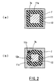
Figure 2 (a) is a cross-sectional view of the swing mechanism ofFigure 1 showing one possible arrangement of a support part of a shaft, and (b) is a cross-sectional view showing another possible arrangement of a support part of a shaft. -
Figure 3 shows one possible arrangement of a roller guide assembly; wherein, (a) is a plan view, and (b) is a front view. -
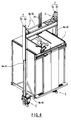
Figure 4 is a perspective view of one possible arrangement of an elevator device. -
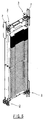
Figure 5 is a perspective view of one possible arrangement of a counterweight with roller guides in accordance with the present invention. - Various exemplary arrangements of the elevator device and the roller guide assembly in accordance with the present invention will be explained below.
- As shown in
Figure 4 , a hoistway (not shown) is formed along the vertical direction, and car 1 that is moved up and down along said hoistway is provided. Car 1 is suspended by one or more hoisting elements, such as thewire rope 20 provided in the figure or a coated steel belt (not shown). A counterweight (not shown) can also be suspended by thewire ropes 20. Although other roping arrangements are possible, in the 1:1 roping arrangement shown in the figure one end of the wire ropes 20 secure to the car 1 and the other end of saidwire ropes 20 secure to the counterweight so as to balance their weights. The elevator system also includesguide rails 2. A pair ofguide rails 2 could be provided along the hoistway at positions corresponding to side surfaces of car 1; and multipleroller guide assemblies 3, which are used for guiding car 1 alongguide rails Figure 5 , another pair of guide rails could be provided along the hoistway at positions corresponding to side surfaces of the counterweight; and multipleroller guide assemblies 3 could be provided at positions near the side surfaces at the top and bottom of the counterweight for guiding the counterweight along theguide rails 2 in order to move the counterweight without causing displacement or tilting of the counterweight within a plane. Other components of the elevator system that are not relevant to the present invention (e.g. safeties, governor assembly, etc.) will not be discussed. - The
aforementioned guide rails 2 comprisesrail body 2a andretainer part 2b for retaining saidrail body 2a and has a quasi-T-shaped cross-section. The pair ofguide rails rail bodies 2a facing each other. The pair ofguide rails rail bodies 2a facing each other, although these guide rails are not necessarily facing the same direction as the car guide rails depending on the hoistway and elevator system arrangement. - The car 1 can be provided with traveling
frame 4 so as to surround car 1 in the vertical direction. Said travelingframe 4 comprises twovertical frames 4a, twotop frames 4b, and twobottom frames 4b; wherein, right and leftvertical frames 4a andbottom frames 4b are provided in contact with the side surfaces and the bottom surface of car 1, andtop frames 4b are provided at a position slightly away from the top surface of car 1. Right and leftvertical frames 4a have a quasi-U-shaped cross section with the opening part facing outward, the twotop frames 4b and twobottom frames 4b have a quasi-T-shaped cross section with the opening part facing upward or downward, and the twotop frames 4b and twobottom frames 4b are connected together while sandwiching right and leftvertical frames 4a respectively. -
Roller guide assemblies 3 are provided at both end positions of aforementioned twotop frame members 4b and twobottom frame members 4b. As shown inFigure 3 , saidroller guide assembly 3 is equipped withpairing rollers sandwich rail body 2a ofguide rail 2 andsingle roller 5c that is provided on the inner side ofpairing rail body 2a so as to roll on the facing surface ofrail body 2a. When saidrollers frame members roller guide assemblies 3 would mount to theframe members - One possible configuration of
roller guide assembly 3 will be explained. As shown inFigure 3(a) ,base member 6 is connected to respective end positions oftop frames 4b andbottom frames 4b that constituteaforementioned traveling frame 4.Notch part 6a is formed on saidbase member 6 so as to accommodaterail body 2a ofguide rail 2. That is,rail body 2a part ofguide rail 2 is placed inside the quasi-U-shaped cross section ofvertical frame 4a ofaforementioned traveling frame 4, andaforementioned notch part 6a is created in order forbase member 6 to stay away from saidrail body 2a. -
Aforementioned rollers guide rail 2, are supported onaforementioned base member 6. That is, threeshaft support members 7 are provided upright onbase member 6; the respectiveshaft support member 7 is provided withshaft 8A that facesaforementioned guide rail 2 and can have a horizontal orientation. Saidshaft 8A comprises aspindle 8,root portion 12 andarm 13; wherein thespindle 8, which also can have a horizontal orientation, is provided viaarm 13 that protrudes above one end ofroot portion 12; androllers spindles 8 respectively. The relationship among these members is shown in the perspective view inFigure 1 . Other configurations, however, are also possible. - Next, one possible configuration of
aforementioned rollers aforementioned rollers roller 5a will be explained.Roller 5a comprisesannular roller periphery 10,roller support part 14 that is fitted inside saidannular roller periphery 10, andbearing 9 that is fitted inside saidroller support part 14.Aforementioned roller periphery 10 is made of a suitable flexible material such as elastic like rubber or urethane.Aforementioned bearing 9 can have a conventional configuration in that multiple steel balls placed between an inner wing and an outer ring. - Next, configuration of the part that supports
aforementioned shaft 8A will be explained based onFigure 2(a) . This part can be configured in the same manner for allrollers Insertion hole 7a is created on aforementionedshaft support member 7, amember 11, made for example from rubber or other suitable materials such as urethane, serving as an elastic member is inserted in saidinsertion hole 7a, andaforementioned root portion 12 of theshaft 8A is inserted inside 11a of saidmember 11. In one embodiment,member 11 is atubular member 11. - In addition, the support part is configured such that
shaft 8A,tubular member 11, andshaft support member 7 have limited rotational movement relative to each other. That is, the outer peripheral surface ofaforementioned root portion 12, the inner peripheral surface of aforementionedtubular member 11, and the inner peripheral surface of aforementionedshaft support member 7 are formed in a polygonal cross-sectional shape, that is, a square in the present embodiment; and the polygon formed on the inner peripheral surfaces of the respective members functions as a restraining means that restrains the respective members from turning relative to each other. Becauseaforementioned tubular member 11 and aforementionedshaft support member 7 may need to be joined more firmly, cure adhesion could be utilized in addition to the fitting of the square cross sections together. - According to this invention, because
root portions 12 of theshaft 8A are supported byshaft support members 7 viatubular members 11, whenrollers guide rails 2 to swing, turning forces are applied to rootportions 12 viaarms 13. Because turning ofroot portions 12 andtubular members 11 relative to each other at the boundary parts of these members is restrained, the outer peripheral surfaces oftubular members 11 are fixed, and the turning forces fromroot portions 12 are applied to their inner peripheral surfaces. Thus, althoughtubular members 11 become twisted due to torsional forces, they return to their original positions as the torsional forces are no longer subsequently applied. Whenrollers guide rails 2, becauserollers guide rails 2 due to the elastic forces oftubular members 11, car 1 is restrained from vibrating; and in the event when an unbalanced load is applied to car 1 for example due to an unbalanced cargo inside car 1, since car 1 is supported byguide rails 2 whiletubular members 11 are being twisted, no excessive force is acted uponrollers tubular members 11 recover from their twisted state subsequently as the effect of the unbalanced load becomes applicable. Saidtubular members 11 achieve a biasing function for biasingrollers guide rails 2, a damper function for restrainingbiased rollers rollers - According to this elevator device and the roller guide assembly, because
tubular member 11 is placed betweenroot portions 12 andshaft support member 7 of the swing mechanism in order to provide the restraining means for restraining these members from turning relative to each other at their boundary part, the twisting oftubular member 11 when the lateral force is acted uponshaft 8A and its subsequent returning to its original position as the lateral force is no longer applied are repeated. As such, unlike in the past, there is no need to provide the swing mechanism with any biasing means or a damper, so the space required for installing the components can be reduced when compared to that required in the past. In addition, because onlytubular member 11 needs to be placed betweenroot portions 12 andshaft support member 7 of the swing mechanism, the manufacturing cost can be reduced when compared to that of the conventional configuration that involved the biasing means and the damper. Furthermore, demands for the prevention of vibrations of various kinds attributable to different elevator structures and elevator speeds can be met, for example, by altering the hardness of the material oftubular member 11 so as to change the spring constant. Moreover, as the assembly becomes worn or deteriorated over years, onlytubular member 11 needs to be replaced without disassembling, assembling, or adjusting the other peripheral parts, so the time spent for maintenance can be reduced. - According to this invention, because the polygonal outer peripheral surface is fitted to the polygonal inner peripheral surface, turning of
tubular member 11 with respect toshaft support member 7 is restrained, and turning ofroot portion 12 with respect to saidtubular member 11 is restrained; whereby, when the turning force is acted upon saidshaft 8A,tubular member 11 is twisted and then returns to its original position subsequently. - According to this elevator device and the roller guide assembly, because the inner and the outer peripheral surfaces of
root portion 12,tubular member 11, andshaft support member 7 are formed in the polygonal cross-sectional shape in order to configure the restraining means, the restraining means can be configured easily. Although shown inFigure 2a as four-sided polygons, theroot portion 12,tubular member 11, andshaft support member 7 could be a three-sided or five or more sided polygons. - When the combination of
roller periphery 10, which could be made of rubber or urethane, and the hardness (spring constant) oftubular member 11 is adjusted, vibrations of car 1 can be restrained under ordinary condition due to the twisting and the restitution oftubular member 11; and in the event car 1 comes to a stop when an emergency stop device is activated, the impact torollers peripheral parts 10 bend. -
Figure 2(b) provides another possible arrangement. Similar components from the aforementioned arrangement are assigned the same reference character and such features are provided without any explanation. Thus, only the different components from the aforementioned arrangement will be explained. - In particular, the configuration of the part that supports
shaft 8A is different. As shown inFigure 2(b) , the outer peripheral surface ofroot portion 12, the inner peripheral surface oftubular member 11, and the inner peripheral surface ofshaft support member 7 are formed in a circular cross-sectional shape. - As one possible alternative (and as specifically shown in
Figure 2(b) ), one ormore recesses 7b can be formed on inner peripheral surface ofshaft support member 7. Therecesses 7b could be positioned roughly at even intervals around the inner periphery of theshaft support member 7. Similarly, one ormore projections 11b could extend from the outer peripheral surface oftubular member 11 in an integrated manner. As shown inFigure 2(b) , therecesses 11a andprojections 11b can be complementary Similarly, one ormore recesses 12a are formed on outer peripheral surface ofroot portion 12. Therecesses 12a could be positioned roughly at even intervals around the outer periphery of theroot portion 12. Similarly, one ormore projections 11c could extend from the inner peripheral surface oftubular member 11 in an integrated manner. As shown inFigure 2(b) , the projections recesses 12a andprojections 11c can be complementary Therecesses projections shaft support member 7 to restrain theshaft 8A from rotation. AlthoughFigure 2(b) shows four (4) recesses and projections between theshaft support member 7 andtubular member 11 and four (4) recesses and projections between thetubular member 11 androot portion 12, any number of recesses and projections could be used. - According to this invention, when
projections tubular member 11 are fitted intorecesses shaft support member 7 androot portion 12, turning oftubular member 11 with respect toshaft support member 7 is restrained, and turning ofroot portion 12 with respect totubular member 11 is restrained; whereby,tubular member 11 is twisted when a turning force is acted upon saidshaft 8A and subsequently returns to its original position. - According to this elevator device and the roller guide assembly, because the restraining means is configured by forming
recesses root portion 12 of theshaft 8A and the inner peripheral surface ofshaft support member 7, and by formingprojections tubular member 11, the restraining means can be configured easily. Alternatively, the projections could extend fromshaft support member 7 andshaft 8A, and the recesses could be ontubular member 11. - As another possible alternative (or in addition to the
aforementioned projections recesses root portion 12,tubular member 11, andshaft support member 7 so as to bond the respective members together in order to enhance the restraining capability of the arrangement. - According to this invention, because the respective members are joined together by the adhesive at the boundary parts, turning of
tubular member 11 with respect toshaft support member 7 is restrained, and turning ofroot portion 12 with respect totubular member 11 is restrained; whereby,tubular member 11 is twisted when a turning force is acted uponshaft 8A and subsequently returns to its original position. - According to this elevator device and the roller guide assembly, because the restraining means is configured by applying the adhesive at the boundary parts of
root portion 12,tubular member 11, andshaft support member 7, the outer peripheral surface ofroot portion 12 and the inner peripheral surface ofshaft support member 7 can be formed in a circular cross-sectional shape, which results in good workability. What is more, because the manufacturing cost is low due to the simple cylindrical shape ofrubber 11, the manufacturing costs of the elevator device and the roller guide assembly are also low. Alternatively, however, the adhesive could be used on different shapes oftubular member 11,shaft support member 7 androot portion 12. - While the present invention has been particularly shown and described with reference to the exemplary embodiments as illustrated in the drawings, it will be recognized by those skilled in the art that various modifications may be made without departing from the scope of the invention as disclosed in the accompanying claims.
Claims (8)
- A roller guide assembly (3) for an elevator device, comprising:a shaft (8A) supporting a roller (5a, 5b, 5c) for engaging a guide rail (2);a shaft support member (7) that receives the shaft (8A) therein; and an elastic member (11) located between the shaft (8A) and the aforementioned shaft support member (7), wherein the member (11) limits the shaft (8A) from turning relative to the shaft support member (7), characterized in that said member (11) is a tubular member.
- The roller guide assembly (3) of Claim 2, wherein the shaft (8A), the member (11), and the shaft support member (7) are formed in a circular cross-sectional shape or a polygonal cross-sectional shape.
- The roller guide assembly (3) of any previous claim, wherein the shaft (8A), member (11), and shaft support member (7) include one or more projections (11b, 11c) and one or more recesses (12a, 7b) to receive said projections (11b, 11c).
- The roller guide assembly (3) of Claim 3, wherein an adhesive is applied to the shaft (8A), member (11), and shaft support member (7) so as to bond the respective members together.
- The roller guide assembly (3) of any preceding Claim, wherein the roller guide assembly (3) includes three rollers (5a, 5b, 5c), and each roller (5a, 5b, 5c) includes a corresponding shaft (8A), shaft support member (7) and member (11).
- The roller guide assembly (3) of any preceding Claim, wherein the roller guide assembly (3) is mounted to a car (1) of the elevator system.
- The roller guide assembly (3) of any preceding Claim, wherein the roller guide assembly (3) is mounted to a counterweight of the elevator system.
- An elevator system, comprising:a car (1) and/or a counterweight; anda roller guide assembly (3) as claimed in any preceding claim mounted to the car (1) and/or counterweight.
Applications Claiming Priority (2)
| Application Number | Priority Date | Filing Date | Title |
|---|---|---|---|
| JP2011132828A JP5902405B2 (en) | 2011-06-15 | 2011-06-15 | Elevator equipment |
| PCT/IB2012/001052 WO2012172400A2 (en) | 2011-06-15 | 2012-05-30 | Elevator device and roller guide assembly |
Publications (3)
| Publication Number | Publication Date |
|---|---|
| EP2720971A2 EP2720971A2 (en) | 2014-04-23 |
| EP2720971A4 EP2720971A4 (en) | 2015-01-28 |
| EP2720971B1 true EP2720971B1 (en) | 2016-09-14 |
Family
ID=47357544
Family Applications (1)
| Application Number | Title | Priority Date | Filing Date |
|---|---|---|---|
| EP12801416.4A Not-in-force EP2720971B1 (en) | 2011-06-15 | 2012-05-30 | Elevator device and roller guide assembly |
Country Status (6)
| Country | Link |
|---|---|
| US (1) | US9434579B2 (en) |
| EP (1) | EP2720971B1 (en) |
| JP (1) | JP5902405B2 (en) |
| CN (1) | CN103619745B (en) |
| ES (1) | ES2593491T3 (en) |
| WO (1) | WO2012172400A2 (en) |
Families Citing this family (11)
| Publication number | Priority date | Publication date | Assignee | Title |
|---|---|---|---|---|
| JP5902405B2 (en) | 2011-06-15 | 2016-04-13 | 日本オーチス・エレベータ株式会社 | Elevator equipment |
| JP5984948B2 (en) * | 2012-09-25 | 2016-09-06 | 三菱電機株式会社 | Roller guide and manufacturing method thereof |
| CN104207724A (en) * | 2014-08-20 | 2014-12-17 | 平湖普英特高层设备有限公司 | Boosted rolling friction mechanism |
| JP6113206B2 (en) * | 2015-01-16 | 2017-04-12 | 三菱電機ビルテクノサービス株式会社 | Elevator balancing weight loading / unloading device |
| JP6141338B2 (en) * | 2015-01-16 | 2017-06-07 | 三菱電機ビルテクノサービス株式会社 | Elevator balancing weight loading / unloading method |
| CN105460737B (en) * | 2015-09-22 | 2018-05-11 | 山东艾德姆机电有限公司 | Rubber torsional cartridge type rolling cage shoe |
| CN105417331B (en) * | 2015-12-28 | 2018-06-26 | 山东艾德姆机电有限公司 | Spring damping cushion wheel cage shoe |
| EP3231757B1 (en) | 2016-04-15 | 2020-04-08 | Otis Elevator Company | Guide rail support |
| EP3301058B1 (en) * | 2016-09-30 | 2024-12-18 | KONE Corporation | Roller guide assembly and elevator system |
| KR102130225B1 (en) * | 2018-12-20 | 2020-07-03 | 현대엘리베이터주식회사 | Guide Roller Assembly of Elevator |
| KR102309532B1 (en) * | 2020-01-22 | 2021-10-07 | 주식회사 휴아이티 | Lifting device for observation equipment of meteorological observation tower |
Citations (1)
| Publication number | Priority date | Publication date | Assignee | Title |
|---|---|---|---|---|
| JPS57117483A (en) * | 1981-01-07 | 1982-07-21 | Hitachi Ltd | Guide apparatus for elevator |
Family Cites Families (17)
| Publication number | Priority date | Publication date | Assignee | Title |
|---|---|---|---|---|
| US3329240A (en) * | 1966-01-07 | 1967-07-04 | Turnbull Elevator Ltd | Elevator roller guide assembly |
| US5107963A (en) * | 1990-01-29 | 1992-04-28 | Norcast Corporation | Spring loaded guide rollers |
| DE4137757C2 (en) * | 1991-11-16 | 1995-02-16 | Schulte Soehne Gmbh Co A | Swivel castor, in particular for movable hospital beds |
| US5667809A (en) | 1995-06-07 | 1997-09-16 | Alliance Pharmaceutical Corp. | Continuous fluorochemical microdispersions for the delivery of lipophilic pharmaceutical agents |
| US5984053A (en) | 1996-10-19 | 1999-11-16 | Lg Industrial Systems Co., Ltd. | Guide roller supporting apparatus for elevator car |
| JPH10194627A (en) | 1996-12-30 | 1998-07-28 | Lg Ind Syst Co Ltd | Elevator guide roller device |
| US5950771A (en) | 1997-12-11 | 1999-09-14 | Otis Elevator Company | Roller guide friction damper |
| US6032764A (en) * | 1997-12-11 | 2000-03-07 | Otis Elevator Company | Roller guide assembly with sound isolation |
| US5950770A (en) | 1998-01-26 | 1999-09-14 | Inventio Ag | Connecting element for elevator guide rail |
| KR19990022587U (en) * | 1999-03-24 | 1999-07-05 | 김덕규 | Elevator guide shoe |
| US6345698B1 (en) * | 2000-02-22 | 2002-02-12 | Otis Elevator Company | Simplified roller guide |
| DE50309764D1 (en) | 2002-04-02 | 2008-06-19 | Inventio Ag | Device for engaging a safety gear for an elevator car |
| JP4183998B2 (en) | 2002-07-26 | 2008-11-19 | 東芝エレベータ株式会社 | Elevator rail anti-rust roller device |
| US7228952B2 (en) | 2004-08-11 | 2007-06-12 | Van Der Graaf Inc. | Conveyor roller shaft support for dampening vibrations |
| WO2007108113A1 (en) | 2006-03-22 | 2007-09-27 | Mitsubishi Denki Kabushiki Kaisha | Support device for elevator guide rail |
| JP5902405B2 (en) | 2011-06-15 | 2016-04-13 | 日本オーチス・エレベータ株式会社 | Elevator equipment |
| WO2013170532A1 (en) * | 2012-05-14 | 2013-11-21 | 杭州沪宁电梯配件有限公司 | Roller guide shoe |
-
2011
- 2011-06-15 JP JP2011132828A patent/JP5902405B2/en active Active
-
2012
- 2012-05-30 EP EP12801416.4A patent/EP2720971B1/en not_active Not-in-force
- 2012-05-30 WO PCT/IB2012/001052 patent/WO2012172400A2/en not_active Ceased
- 2012-05-30 ES ES12801416.4T patent/ES2593491T3/en active Active
- 2012-05-30 CN CN201280029082.1A patent/CN103619745B/en not_active Expired - Fee Related
- 2012-05-30 US US14/125,381 patent/US9434579B2/en active Active
Patent Citations (1)
| Publication number | Priority date | Publication date | Assignee | Title |
|---|---|---|---|---|
| JPS57117483A (en) * | 1981-01-07 | 1982-07-21 | Hitachi Ltd | Guide apparatus for elevator |
Also Published As
| Publication number | Publication date |
|---|---|
| JP5902405B2 (en) | 2016-04-13 |
| CN103619745A (en) | 2014-03-05 |
| US20140102833A1 (en) | 2014-04-17 |
| EP2720971A2 (en) | 2014-04-23 |
| JP2013001485A (en) | 2013-01-07 |
| WO2012172400A2 (en) | 2012-12-20 |
| WO2012172400A3 (en) | 2013-02-21 |
| US9434579B2 (en) | 2016-09-06 |
| EP2720971A4 (en) | 2015-01-28 |
| CN103619745B (en) | 2017-02-15 |
| ES2593491T3 (en) | 2016-12-09 |
Similar Documents
| Publication | Publication Date | Title |
|---|---|---|
| US9434579B2 (en) | Elevator device and roller guide assembly | |
| JP5655143B2 (en) | Elevator device and roller guide assembly | |
| CN104583113B (en) | The counterweight of elevator | |
| CN102112386B (en) | Vibration isolation components for elevator systems | |
| JP2007119131A (en) | Elevator rope swing prevention device | |
| WO2004022471A1 (en) | Elevator device | |
| JP4765444B2 (en) | Elevator rope steady rest | |
| HK1195295B (en) | Elevator device and roller guide assembly | |
| HK1195295A (en) | Elevator device and roller guide assembly | |
| JP7052892B1 (en) | Elevator car device and elevator | |
| JP2009155087A (en) | Elevator device | |
| WO2024018564A1 (en) | Elevator device | |
| JP5184563B2 (en) | Double deck elevator | |
| JP2005096975A (en) | Elevator for base-isolated building | |
| KR102433955B1 (en) | Guide Roller for Roller Guide System of Elevator | |
| KR102729976B1 (en) | Pully for elevator and elevator system having the same | |
| JP7086510B2 (en) | Elevator jump prevention device | |
| WO2014006667A1 (en) | Device for stopping elevator rope deflection | |
| KR20240033820A (en) | Guide roller device for elevator | |
| KR101855487B1 (en) | Descending device for escape | |
| JP5505976B2 (en) | elevator | |
| JPH04197978A (en) | Elevator guide device | |
| HK1159582B (en) | Vibration isolation assembly for an elevator system | |
| HK1182368A1 (en) | Elevator installation having a self-centering car door mounting |
Legal Events
| Date | Code | Title | Description |
|---|---|---|---|
| PUAI | Public reference made under article 153(3) epc to a published international application that has entered the european phase |
Free format text: ORIGINAL CODE: 0009012 |
|
| 17P | Request for examination filed |
Effective date: 20140113 |
|
| AK | Designated contracting states |
Kind code of ref document: A2 Designated state(s): AL AT BE BG CH CY CZ DE DK EE ES FI FR GB GR HR HU IE IS IT LI LT LU LV MC MK MT NL NO PL PT RO RS SE SI SK SM TR |
|
| DAX | Request for extension of the european patent (deleted) | ||
| A4 | Supplementary search report drawn up and despatched |
Effective date: 20150107 |
|
| RIC1 | Information provided on ipc code assigned before grant |
Ipc: B66B 7/02 20060101AFI20141219BHEP Ipc: B66B 7/04 20060101ALI20141219BHEP Ipc: F16C 3/00 20060101ALI20141219BHEP |
|
| GRAP | Despatch of communication of intention to grant a patent |
Free format text: ORIGINAL CODE: EPIDOSNIGR1 |
|
| INTG | Intention to grant announced |
Effective date: 20160330 |
|
| GRAS | Grant fee paid |
Free format text: ORIGINAL CODE: EPIDOSNIGR3 |
|
| GRAA | (expected) grant |
Free format text: ORIGINAL CODE: 0009210 |
|
| AK | Designated contracting states |
Kind code of ref document: B1 Designated state(s): AL AT BE BG CH CY CZ DE DK EE ES FI FR GB GR HR HU IE IS IT LI LT LU LV MC MK MT NL NO PL PT RO RS SE SI SK SM TR |
|
| REG | Reference to a national code |
Ref country code: GB Ref legal event code: FG4D |
|
| REG | Reference to a national code |
Ref country code: CH Ref legal event code: EP |
|
| REG | Reference to a national code |
Ref country code: IE Ref legal event code: FG4D |
|
| REG | Reference to a national code |
Ref country code: AT Ref legal event code: REF Ref document number: 828737 Country of ref document: AT Kind code of ref document: T Effective date: 20161015 |
|
| REG | Reference to a national code |
Ref country code: DE Ref legal event code: R096 Ref document number: 602012023021 Country of ref document: DE |
|
| REG | Reference to a national code |
Ref country code: ES Ref legal event code: FG2A Ref document number: 2593491 Country of ref document: ES Kind code of ref document: T3 Effective date: 20161209 |
|
| REG | Reference to a national code |
Ref country code: LT Ref legal event code: MG4D |
|
| REG | Reference to a national code |
Ref country code: NL Ref legal event code: MP Effective date: 20160914 |
|
| PG25 | Lapsed in a contracting state [announced via postgrant information from national office to epo] |
Ref country code: RS Free format text: LAPSE BECAUSE OF FAILURE TO SUBMIT A TRANSLATION OF THE DESCRIPTION OR TO PAY THE FEE WITHIN THE PRESCRIBED TIME-LIMIT Effective date: 20160914 Ref country code: LT Free format text: LAPSE BECAUSE OF FAILURE TO SUBMIT A TRANSLATION OF THE DESCRIPTION OR TO PAY THE FEE WITHIN THE PRESCRIBED TIME-LIMIT Effective date: 20160914 Ref country code: FI Free format text: LAPSE BECAUSE OF FAILURE TO SUBMIT A TRANSLATION OF THE DESCRIPTION OR TO PAY THE FEE WITHIN THE PRESCRIBED TIME-LIMIT Effective date: 20160914 Ref country code: HR Free format text: LAPSE BECAUSE OF FAILURE TO SUBMIT A TRANSLATION OF THE DESCRIPTION OR TO PAY THE FEE WITHIN THE PRESCRIBED TIME-LIMIT Effective date: 20160914 Ref country code: NO Free format text: LAPSE BECAUSE OF FAILURE TO SUBMIT A TRANSLATION OF THE DESCRIPTION OR TO PAY THE FEE WITHIN THE PRESCRIBED TIME-LIMIT Effective date: 20161214 |
|
| REG | Reference to a national code |
Ref country code: AT Ref legal event code: MK05 Ref document number: 828737 Country of ref document: AT Kind code of ref document: T Effective date: 20160914 |
|
| PG25 | Lapsed in a contracting state [announced via postgrant information from national office to epo] |
Ref country code: GR Free format text: LAPSE BECAUSE OF FAILURE TO SUBMIT A TRANSLATION OF THE DESCRIPTION OR TO PAY THE FEE WITHIN THE PRESCRIBED TIME-LIMIT Effective date: 20161215 Ref country code: SE Free format text: LAPSE BECAUSE OF FAILURE TO SUBMIT A TRANSLATION OF THE DESCRIPTION OR TO PAY THE FEE WITHIN THE PRESCRIBED TIME-LIMIT Effective date: 20160914 Ref country code: LV Free format text: LAPSE BECAUSE OF FAILURE TO SUBMIT A TRANSLATION OF THE DESCRIPTION OR TO PAY THE FEE WITHIN THE PRESCRIBED TIME-LIMIT Effective date: 20160914 Ref country code: NL Free format text: LAPSE BECAUSE OF FAILURE TO SUBMIT A TRANSLATION OF THE DESCRIPTION OR TO PAY THE FEE WITHIN THE PRESCRIBED TIME-LIMIT Effective date: 20160914 |
|
| REG | Reference to a national code |
Ref country code: FR Ref legal event code: PLFP Year of fee payment: 6 |
|
| PG25 | Lapsed in a contracting state [announced via postgrant information from national office to epo] |
Ref country code: RO Free format text: LAPSE BECAUSE OF FAILURE TO SUBMIT A TRANSLATION OF THE DESCRIPTION OR TO PAY THE FEE WITHIN THE PRESCRIBED TIME-LIMIT Effective date: 20160914 Ref country code: EE Free format text: LAPSE BECAUSE OF FAILURE TO SUBMIT A TRANSLATION OF THE DESCRIPTION OR TO PAY THE FEE WITHIN THE PRESCRIBED TIME-LIMIT Effective date: 20160914 |
|
| PG25 | Lapsed in a contracting state [announced via postgrant information from national office to epo] |
Ref country code: PT Free format text: LAPSE BECAUSE OF FAILURE TO SUBMIT A TRANSLATION OF THE DESCRIPTION OR TO PAY THE FEE WITHIN THE PRESCRIBED TIME-LIMIT Effective date: 20170116 Ref country code: IS Free format text: LAPSE BECAUSE OF FAILURE TO SUBMIT A TRANSLATION OF THE DESCRIPTION OR TO PAY THE FEE WITHIN THE PRESCRIBED TIME-LIMIT Effective date: 20170114 Ref country code: BG Free format text: LAPSE BECAUSE OF FAILURE TO SUBMIT A TRANSLATION OF THE DESCRIPTION OR TO PAY THE FEE WITHIN THE PRESCRIBED TIME-LIMIT Effective date: 20161214 Ref country code: AT Free format text: LAPSE BECAUSE OF FAILURE TO SUBMIT A TRANSLATION OF THE DESCRIPTION OR TO PAY THE FEE WITHIN THE PRESCRIBED TIME-LIMIT Effective date: 20160914 Ref country code: PL Free format text: LAPSE BECAUSE OF FAILURE TO SUBMIT A TRANSLATION OF THE DESCRIPTION OR TO PAY THE FEE WITHIN THE PRESCRIBED TIME-LIMIT Effective date: 20160914 Ref country code: SM Free format text: LAPSE BECAUSE OF FAILURE TO SUBMIT A TRANSLATION OF THE DESCRIPTION OR TO PAY THE FEE WITHIN THE PRESCRIBED TIME-LIMIT Effective date: 20160914 Ref country code: BE Free format text: LAPSE BECAUSE OF FAILURE TO SUBMIT A TRANSLATION OF THE DESCRIPTION OR TO PAY THE FEE WITHIN THE PRESCRIBED TIME-LIMIT Effective date: 20160914 Ref country code: CZ Free format text: LAPSE BECAUSE OF FAILURE TO SUBMIT A TRANSLATION OF THE DESCRIPTION OR TO PAY THE FEE WITHIN THE PRESCRIBED TIME-LIMIT Effective date: 20160914 Ref country code: SK Free format text: LAPSE BECAUSE OF FAILURE TO SUBMIT A TRANSLATION OF THE DESCRIPTION OR TO PAY THE FEE WITHIN THE PRESCRIBED TIME-LIMIT Effective date: 20160914 |
|
| REG | Reference to a national code |
Ref country code: DE Ref legal event code: R097 Ref document number: 602012023021 Country of ref document: DE |
|
| PG25 | Lapsed in a contracting state [announced via postgrant information from national office to epo] |
Ref country code: IT Free format text: LAPSE BECAUSE OF FAILURE TO SUBMIT A TRANSLATION OF THE DESCRIPTION OR TO PAY THE FEE WITHIN THE PRESCRIBED TIME-LIMIT Effective date: 20160914 |
|
| REG | Reference to a national code |
Ref country code: DE Ref legal event code: R082 Ref document number: 602012023021 Country of ref document: DE Representative=s name: SCHMITT-NILSON SCHRAUD WAIBEL WOHLFROM PATENTA, DE |
|
| PLBE | No opposition filed within time limit |
Free format text: ORIGINAL CODE: 0009261 |
|
| STAA | Information on the status of an ep patent application or granted ep patent |
Free format text: STATUS: NO OPPOSITION FILED WITHIN TIME LIMIT |
|
| PG25 | Lapsed in a contracting state [announced via postgrant information from national office to epo] |
Ref country code: DK Free format text: LAPSE BECAUSE OF FAILURE TO SUBMIT A TRANSLATION OF THE DESCRIPTION OR TO PAY THE FEE WITHIN THE PRESCRIBED TIME-LIMIT Effective date: 20160914 |
|
| 26N | No opposition filed |
Effective date: 20170615 |
|
| PG25 | Lapsed in a contracting state [announced via postgrant information from national office to epo] |
Ref country code: LU Free format text: LAPSE BECAUSE OF NON-PAYMENT OF DUE FEES Effective date: 20170531 |
|
| PG25 | Lapsed in a contracting state [announced via postgrant information from national office to epo] |
Ref country code: SI Free format text: LAPSE BECAUSE OF FAILURE TO SUBMIT A TRANSLATION OF THE DESCRIPTION OR TO PAY THE FEE WITHIN THE PRESCRIBED TIME-LIMIT Effective date: 20160914 |
|
| REG | Reference to a national code |
Ref country code: CH Ref legal event code: PL |
|
| GBPC | Gb: european patent ceased through non-payment of renewal fee |
Effective date: 20170530 |
|
| PG25 | Lapsed in a contracting state [announced via postgrant information from national office to epo] |
Ref country code: MC Free format text: LAPSE BECAUSE OF FAILURE TO SUBMIT A TRANSLATION OF THE DESCRIPTION OR TO PAY THE FEE WITHIN THE PRESCRIBED TIME-LIMIT Effective date: 20160914 |
|
| REG | Reference to a national code |
Ref country code: IE Ref legal event code: MM4A |
|
| PG25 | Lapsed in a contracting state [announced via postgrant information from national office to epo] |
Ref country code: CH Free format text: LAPSE BECAUSE OF NON-PAYMENT OF DUE FEES Effective date: 20170531 Ref country code: LI Free format text: LAPSE BECAUSE OF NON-PAYMENT OF DUE FEES Effective date: 20170531 |
|
| PG25 | Lapsed in a contracting state [announced via postgrant information from national office to epo] |
Ref country code: LU Free format text: LAPSE BECAUSE OF NON-PAYMENT OF DUE FEES Effective date: 20170530 |
|
| REG | Reference to a national code |
Ref country code: FR Ref legal event code: PLFP Year of fee payment: 7 |
|
| PG25 | Lapsed in a contracting state [announced via postgrant information from national office to epo] |
Ref country code: GB Free format text: LAPSE BECAUSE OF NON-PAYMENT OF DUE FEES Effective date: 20170530 Ref country code: IE Free format text: LAPSE BECAUSE OF NON-PAYMENT OF DUE FEES Effective date: 20170530 |
|
| PG25 | Lapsed in a contracting state [announced via postgrant information from national office to epo] |
Ref country code: MT Free format text: LAPSE BECAUSE OF NON-PAYMENT OF DUE FEES Effective date: 20170530 |
|
| PG25 | Lapsed in a contracting state [announced via postgrant information from national office to epo] |
Ref country code: AL Free format text: LAPSE BECAUSE OF FAILURE TO SUBMIT A TRANSLATION OF THE DESCRIPTION OR TO PAY THE FEE WITHIN THE PRESCRIBED TIME-LIMIT Effective date: 20160914 |
|
| PG25 | Lapsed in a contracting state [announced via postgrant information from national office to epo] |
Ref country code: HU Free format text: LAPSE BECAUSE OF FAILURE TO SUBMIT A TRANSLATION OF THE DESCRIPTION OR TO PAY THE FEE WITHIN THE PRESCRIBED TIME-LIMIT; INVALID AB INITIO Effective date: 20120530 |
|
| PG25 | Lapsed in a contracting state [announced via postgrant information from national office to epo] |
Ref country code: CY Free format text: LAPSE BECAUSE OF NON-PAYMENT OF DUE FEES Effective date: 20160914 |
|
| PG25 | Lapsed in a contracting state [announced via postgrant information from national office to epo] |
Ref country code: MK Free format text: LAPSE BECAUSE OF FAILURE TO SUBMIT A TRANSLATION OF THE DESCRIPTION OR TO PAY THE FEE WITHIN THE PRESCRIBED TIME-LIMIT Effective date: 20160914 |
|
| PG25 | Lapsed in a contracting state [announced via postgrant information from national office to epo] |
Ref country code: TR Free format text: LAPSE BECAUSE OF FAILURE TO SUBMIT A TRANSLATION OF THE DESCRIPTION OR TO PAY THE FEE WITHIN THE PRESCRIBED TIME-LIMIT Effective date: 20160914 |
|
| PGFP | Annual fee paid to national office [announced via postgrant information from national office to epo] |
Ref country code: DE Payment date: 20240418 Year of fee payment: 13 |
|
| PGFP | Annual fee paid to national office [announced via postgrant information from national office to epo] |
Ref country code: ES Payment date: 20240603 Year of fee payment: 13 |
|
| PGFP | Annual fee paid to national office [announced via postgrant information from national office to epo] |
Ref country code: FR Payment date: 20240418 Year of fee payment: 13 |
|
| REG | Reference to a national code |
Ref country code: DE Ref legal event code: R119 Ref document number: 602012023021 Country of ref document: DE |
|
| PG25 | Lapsed in a contracting state [announced via postgrant information from national office to epo] |
Ref country code: DE Free format text: LAPSE BECAUSE OF NON-PAYMENT OF DUE FEES Effective date: 20251202 |
|
| PG25 | Lapsed in a contracting state [announced via postgrant information from national office to epo] |
Ref country code: FR Free format text: LAPSE BECAUSE OF NON-PAYMENT OF DUE FEES Effective date: 20250531 |
|
| REG | Reference to a national code |
Ref country code: ES Ref legal event code: FD2A Effective date: 20260703 |
|
| PG25 | Lapsed in a contracting state [announced via postgrant information from national office to epo] |
Ref country code: ES Free format text: LAPSE BECAUSE OF NON-PAYMENT OF DUE FEES Effective date: 20250531 |