EP2720428B1 - Method and device for information transmission in wireless communication system - Google Patents
Method and device for information transmission in wireless communication system Download PDFInfo
- Publication number
- EP2720428B1 EP2720428B1 EP12797583.7A EP12797583A EP2720428B1 EP 2720428 B1 EP2720428 B1 EP 2720428B1 EP 12797583 A EP12797583 A EP 12797583A EP 2720428 B1 EP2720428 B1 EP 2720428B1
- Authority
- EP
- European Patent Office
- Prior art keywords
- subframe
- epdcch
- pucch
- information
- pdcch
- Prior art date
- Legal status (The legal status is an assumption and is not a legal conclusion. Google has not performed a legal analysis and makes no representation as to the accuracy of the status listed.)
- Active
Links
- 230000005540 biological transmission Effects 0.000 title claims description 145
- 238000000034 method Methods 0.000 title claims description 58
- 238000004891 communication Methods 0.000 title claims description 26
- 238000005259 measurement Methods 0.000 claims description 32
- 230000011664 signaling Effects 0.000 claims description 11
- 230000007774 longterm Effects 0.000 claims 2
- 101000741965 Homo sapiens Inactive tyrosine-protein kinase PRAG1 Proteins 0.000 description 172
- 102100038659 Inactive tyrosine-protein kinase PRAG1 Human genes 0.000 description 172
- 102100036409 Activated CDC42 kinase 1 Human genes 0.000 description 160
- 229920000122 acrylonitrile butadiene styrene Polymers 0.000 description 64
- 239000000969 carrier Substances 0.000 description 29
- 238000012545 processing Methods 0.000 description 21
- 238000007726 management method Methods 0.000 description 20
- 238000013507 mapping Methods 0.000 description 20
- 230000004044 response Effects 0.000 description 19
- 108010003272 Hyaluronate lyase Proteins 0.000 description 17
- 230000015654 memory Effects 0.000 description 16
- 102100035727 Probable ATP-dependent RNA helicase DDX41 Human genes 0.000 description 13
- 230000002776 aggregation Effects 0.000 description 13
- 238000004220 aggregation Methods 0.000 description 13
- 230000007480 spreading Effects 0.000 description 12
- 230000006870 function Effects 0.000 description 11
- 238000012544 monitoring process Methods 0.000 description 9
- 125000004122 cyclic group Chemical group 0.000 description 5
- 230000008569 process Effects 0.000 description 5
- 230000002123 temporal effect Effects 0.000 description 5
- 230000000694 effects Effects 0.000 description 4
- 238000005516 engineering process Methods 0.000 description 4
- 230000004913 activation Effects 0.000 description 3
- 238000001514 detection method Methods 0.000 description 3
- 238000012986 modification Methods 0.000 description 3
- 230000004048 modification Effects 0.000 description 3
- 230000008054 signal transmission Effects 0.000 description 3
- KWYHDKDOAIKMQN-UHFFFAOYSA-N N,N,N',N'-tetramethylethylenediamine Chemical compound CN(C)CCN(C)C KWYHDKDOAIKMQN-UHFFFAOYSA-N 0.000 description 2
- 238000013459 approach Methods 0.000 description 2
- 238000003491 array Methods 0.000 description 2
- 239000000872 buffer Substances 0.000 description 2
- 238000004364 calculation method Methods 0.000 description 2
- 230000000116 mitigating effect Effects 0.000 description 2
- 238000010295 mobile communication Methods 0.000 description 2
- 230000000737 periodic effect Effects 0.000 description 2
- 230000010363 phase shift Effects 0.000 description 2
- 230000002829 reductive effect Effects 0.000 description 2
- 238000013468 resource allocation Methods 0.000 description 2
- -1 CQI Proteins 0.000 description 1
- 241000760358 Enodes Species 0.000 description 1
- MGSKVZWGBWPBTF-UHFFFAOYSA-N aebsf Chemical compound NCCC1=CC=C(S(F)(=O)=O)C=C1 MGSKVZWGBWPBTF-UHFFFAOYSA-N 0.000 description 1
- 230000001413 cellular effect Effects 0.000 description 1
- 230000003247 decreasing effect Effects 0.000 description 1
- 230000001934 delay Effects 0.000 description 1
- 230000001419 dependent effect Effects 0.000 description 1
- 238000013461 design Methods 0.000 description 1
- 238000010586 diagram Methods 0.000 description 1
- 238000005562 fading Methods 0.000 description 1
- 230000002452 interceptive effect Effects 0.000 description 1
- 230000000670 limiting effect Effects 0.000 description 1
- 239000011159 matrix material Substances 0.000 description 1
- 230000003287 optical effect Effects 0.000 description 1
- 230000001151 other effect Effects 0.000 description 1
- 230000002085 persistent effect Effects 0.000 description 1
- 238000011160 research Methods 0.000 description 1
- 238000005070 sampling Methods 0.000 description 1
- 238000001228 spectrum Methods 0.000 description 1
- 230000003068 static effect Effects 0.000 description 1
Images


Classifications
-
- H—ELECTRICITY
- H04—ELECTRIC COMMUNICATION TECHNIQUE
- H04W—WIRELESS COMMUNICATION NETWORKS
- H04W72/00—Local resource management
- H04W72/04—Wireless resource allocation
- H04W72/044—Wireless resource allocation based on the type of the allocated resource
-
- H—ELECTRICITY
- H04—ELECTRIC COMMUNICATION TECHNIQUE
- H04L—TRANSMISSION OF DIGITAL INFORMATION, e.g. TELEGRAPHIC COMMUNICATION
- H04L27/00—Modulated-carrier systems
- H04L27/26—Systems using multi-frequency codes
-
- H—ELECTRICITY
- H04—ELECTRIC COMMUNICATION TECHNIQUE
- H04L—TRANSMISSION OF DIGITAL INFORMATION, e.g. TELEGRAPHIC COMMUNICATION
- H04L27/00—Modulated-carrier systems
- H04L27/26—Systems using multi-frequency codes
- H04L27/2601—Multicarrier modulation systems
- H04L27/2626—Arrangements specific to the transmitter only
- H04L27/2627—Modulators
- H04L27/2634—Inverse fast Fourier transform [IFFT] or inverse discrete Fourier transform [IDFT] modulators in combination with other circuits for modulation
- H04L27/2636—Inverse fast Fourier transform [IFFT] or inverse discrete Fourier transform [IDFT] modulators in combination with other circuits for modulation with FFT or DFT modulators, e.g. standard single-carrier frequency-division multiple access [SC-FDMA] transmitter or DFT spread orthogonal frequency division multiplexing [DFT-SOFDM]
-
- H—ELECTRICITY
- H04—ELECTRIC COMMUNICATION TECHNIQUE
- H04L—TRANSMISSION OF DIGITAL INFORMATION, e.g. TELEGRAPHIC COMMUNICATION
- H04L5/00—Arrangements affording multiple use of the transmission path
- H04L5/0091—Signaling for the administration of the divided path
- H04L5/0094—Indication of how sub-channels of the path are allocated
-
- H—ELECTRICITY
- H04—ELECTRIC COMMUNICATION TECHNIQUE
- H04W—WIRELESS COMMUNICATION NETWORKS
- H04W72/00—Local resource management
- H04W72/04—Wireless resource allocation
-
- H—ELECTRICITY
- H04—ELECTRIC COMMUNICATION TECHNIQUE
- H04L—TRANSMISSION OF DIGITAL INFORMATION, e.g. TELEGRAPHIC COMMUNICATION
- H04L1/00—Arrangements for detecting or preventing errors in the information received
- H04L1/0001—Systems modifying transmission characteristics according to link quality, e.g. power backoff
- H04L1/0023—Systems modifying transmission characteristics according to link quality, e.g. power backoff characterised by the signalling
- H04L1/0026—Transmission of channel quality indication
-
- H—ELECTRICITY
- H04—ELECTRIC COMMUNICATION TECHNIQUE
- H04L—TRANSMISSION OF DIGITAL INFORMATION, e.g. TELEGRAPHIC COMMUNICATION
- H04L1/00—Arrangements for detecting or preventing errors in the information received
- H04L1/12—Arrangements for detecting or preventing errors in the information received by using return channel
- H04L1/16—Arrangements for detecting or preventing errors in the information received by using return channel in which the return channel carries supervisory signals, e.g. repetition request signals
- H04L1/18—Automatic repetition systems, e.g. Van Duuren systems
- H04L1/1812—Hybrid protocols; Hybrid automatic repeat request [HARQ]
-
- H—ELECTRICITY
- H04—ELECTRIC COMMUNICATION TECHNIQUE
- H04L—TRANSMISSION OF DIGITAL INFORMATION, e.g. TELEGRAPHIC COMMUNICATION
- H04L5/00—Arrangements affording multiple use of the transmission path
- H04L5/0001—Arrangements for dividing the transmission path
- H04L5/0003—Two-dimensional division
- H04L5/0005—Time-frequency
- H04L5/0007—Time-frequency the frequencies being orthogonal, e.g. OFDM(A), DMT
- H04L5/001—Time-frequency the frequencies being orthogonal, e.g. OFDM(A), DMT the frequencies being arranged in component carriers
-
- H—ELECTRICITY
- H04—ELECTRIC COMMUNICATION TECHNIQUE
- H04L—TRANSMISSION OF DIGITAL INFORMATION, e.g. TELEGRAPHIC COMMUNICATION
- H04L5/00—Arrangements affording multiple use of the transmission path
- H04L5/003—Arrangements for allocating sub-channels of the transmission path
- H04L5/0053—Allocation of signaling, i.e. of overhead other than pilot signals
-
- H—ELECTRICITY
- H04—ELECTRIC COMMUNICATION TECHNIQUE
- H04W—WIRELESS COMMUNICATION NETWORKS
- H04W72/00—Local resource management
- H04W72/20—Control channels or signalling for resource management
- H04W72/23—Control channels or signalling for resource management in the downlink direction of a wireless link, i.e. towards a terminal
Definitions
- the present invention relates to a wireless communication system, and more particularly, to a method and device for transmitting information.
- the wireless communication system supports carrier aggregation (CA).
- CA carrier aggregation
- a wireless communication system is a multiple access system that supports communication among multiple users by sharing available system resources (e.g. bandwidth, transmit power, etc.) among the multiple users.
- the multiple access system may adopt a multiple access scheme such as code division multiple access (CDMA), frequency division multiple access (FDMA), time division multiple access (TDMA), orthogonal frequency division multiple access (OFDMA), or single carrier frequency division multiple access (SC-FDMA).
- CDMA code division multiple access
- FDMA frequency division multiple access
- TDMA time division multiple access
- OFDMA orthogonal frequency division multiple access
- SC-FDMA single carrier frequency division multiple access
- LTE Evolved Universal Terrestrial Radio Access
- E-UTRA Evolved Universal Terrestrial Radio Access
- 3GPP TS 36.213 version 10.1.0 Release 10) 1 April 2011 is the technical specification for LTE.
- the object of the present invention can be achieved by providing a method and a user equipment according to the independent claims. Further embodiments are described in the dependent claims.
- the present invention it is possible to efficiently transmit information in a wireless communication system.
- CDMA Code Division Multiple Access
- FDMA Frequency Division Multiple Access
- TDMA Time Division Multiple Access
- OFDMA Orthogonal Frequency Division Multiple Access
- SC-FDMA Single Carrier-Frequency Division Multiple Access
- CDMA may be implemented as a radio technology such as Universal Terrestrial Radio Access (UTRA) or CDMA2000.
- TDMA may be implemented as a radio technology such as Global System for Mobile communications (GSM)/General Packet Radio Service (GPRS)/Enhanced Data Rates for GSM Evolution (EDGE).
- GSM Global System for Mobile communications
- GPRS General Packet Radio Service
- EDGE Enhanced Data Rates for GSM Evolution
- OFDMA may be implemented as a radio technology such as IEEE 802.11 (Wi-Fi), IEEE 802.16 (WiMAX), IEEE 802.20, Evolved-UTRA (E-UTRA) etc.
- UTRA is a part of Universal Mobile Telecommunication System (UMTS).
- 3GPP LTE is a part of Evolved UMTS (E-UMTS) using E-UTRA.
- 3GPP LTE employs OFDMA for downlink and SC-FDMA for uplink.
- LTE-A is evolved from 3GPP LTE. For clarity, the following description focuses on 3GPP LTE/LTE-A. However, technical features of the present invention are not limited thereto. For example, even if the following description is made based on a wireless communication system corresponding to 3GPP LTE/LTT-A, the present invention is applicable to other wireless communication systems except for specific features of 3GPP LTE/LTE-A.
- a terminal refers to a device that can be fixed or mobile and communicates with a base station to transmit/receive various types of data and control information.
- the term “terminal” may be used interchangeably with terms “user equipment (UE)”, “mobile station (MS)”, “mobile terminal (MT)”, “user terminal (UT)”, “subscriber station (SS)”, “wireless device”, “personal digital assistant (PDA)”, “wireless modem”, “handheld device”, etc.
- a base station refers to a fixed station communicating with UEs or other base stations and communicates with UEs and other base stations to exchange various types of data and information with the same.
- the base station may be referred to as evolved-nodeB (eNB), base transceiver system (BTS), access point (AP), etc.
- eNB evolved-nodeB
- BTS base transceiver system
- AP access point
- allocation of a specific signal to a frame/subframe/slot/carrier/subcarrier refers to transmission of the specific signal through the corresponding carrier/subcarrier for the duration or at the timing of the corresponding frame/subframe/slot.
- a rank or a transport rank refers to the number of layers multiplexed or allocated to a single OFDM symbol or a single resource element.
- PDCCH physical downlink control channel
- PCFICH physical control format indicator channel
- PHICH physical hybrid automatic retransmit request indicator channel
- PDSCH physical downlink shared channel
- DCI downlink control information
- CFI control format indicator
- ACK/NACK acknowledgement/negative ACK
- PUCCH Physical uplink control channel
- PUSCH physical uplink shared channel
- PRACH physical random access channel
- UCI uplink control information
- resource elements (REs) allocated or belonging to PDCCH/PCFICH/PHICH/PDSCH/PUCCH/PUSCH/PRACH are referred to as PDCCH/PCFICH/ PHICH/PDSCH/PUCCH/PUSCH/PRACH REs or PDCCH/PCFICH/ PHICH/PDSCH/PUCCH/PUSCH/PRACH resources.
- transmission of PUCCH/PUSCH/PRACH by a UE corresponds to transmission of UCI/uplink data/random access signal on PUSCH/PUCCH/PRACH.
- transmission of PDCCH/PCFICH/PHICH/PDSCH by a BS corresponds to transmission of DCI/downlink data on PDCCH/PCFICH/PHICH/PDSCH.
- mapping of ACK/NACK information to a specific constellation point corresponds to mapping of the ACK/NACK information to a specific complex modulation symbol.
- mapping of ACK/NACK information to a specific complex modulation symbol corresponds to modulation of the ACK/NACK information into the specific complex modulation symbol.
- FIG. 1 illustrates configurations of a UE and a BS to which the present invention is applicable.
- the UE serves as a transmitter on uplink and operates as a receiver on downlink.
- the BS operates as a receiver on uplink and functions as a transmitter on downlink.
- the UE and the BS respectively include antennas 500a and 500b for receiving information, data, signals or messages, transmitters 100a and 100b for transmitting information, data, signals or messages by controlling the antennas, receivers 300a and 300b for receiving information, data, signals or messages by controlling the antennas, and memories 200a and 200b temporarily or permanently storing information regarding the wireless communication system.
- the UE and the BS respectively include processors 400a and 400b connected to components such as the transmitters, receivers and memories and configured to control the components.
- the transmitter 100a, the receiver 300a, the memory 200a and processor 400a included in the UE may be implemented as independent components by respective chips or two or more thereof may be implemented as a single chip.
- the transmitter 100b, the receiver 300b, the memory 200b and processor 400b included in the BS may be implemented as independent components by respective chips or two or more thereof may be implemented as a single chip.
- the transmitter and receiver may be integrated into a transceiver in the UE or BS.
- the antennas 500a and 500b transmit signals generated in the transmitters 100a and 100b to the outside or receive external signals and deliver the received signals to the receivers 300a and 300b.
- the antennas 500a and 500b are also called antenna ports.
- An antenna port may correspond to a physical antenna or a combination of a plurality of physical antennas.
- a transceiver supporting MIMO (multiple input multiple output) for transmitting/receiving data using multiple antennas may be connected to two or more antennas.
- the processors 400a and 400b control the overall operation of components or modules included in the UE or BS. Particularly, the processors 400a and 400b may execute various control functions for performing the present invention, a MAC (medium access control) frame variation control function according to service characteristics and propagation environment, a power saving mode function for controlling idle operation, a handover function, authentication and encoding functions, etc.
- the processors 400a and 400b may be called controllers, microcontrollers, microprocessors or microcomputers.
- the processors 400a and 400b may be implemented by hardware, firmware, software or a combination thereof.
- ASICs application specific integrated circuits
- DSPs digital signal processors
- DSPDs digital signal processing devices
- PLDs programmable logic devices
- FPGAs field programmable gate arrays
- the embodiments of the present invention may be implemented in the form of a module, a procedure, a function, etc.
- Firmware or software configured to implement the present invention may be included in the processors 400a and 400b or stored in the memories 200a and 200b and executed by the processors 400a and 400b.
- the transmitters 100a and 100b perform predetermined coding and modulation on a signal or data, which is scheduled by the processors 400a and 400b or a scheduler connected to the processors and transmitted to the outside, and transmit the modulated signal or data to the antennas 500a and 500b.
- the transmitters 100a and 100b and the receivers 300a and 300b of the UE and BS may be configured in a different manner according to a procedure of processing a transmitted signal and a received signal.
- the memories 200a and 200b may store programs for processing and control of the processors 400a and 400b and temporarily store input/output information. Furthermore, the memories 200a and 200b may be used as buffers.
- the memories may be implemented using flash memory, a hard disc, a multimedia card micro type or card type memory (e.g. SD or XD memory), a random access memory (RAM), a static RAM (SRAM), a read-only memory (ROM), an electrically erasable programmable read-only memory (EEPROM), a programmable ROM (PROM), a magnetic memory, a magnetic disc, an optical disc, etc.
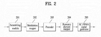
- FIG. 2 illustrates a signal processing procedure through which a UE transmits an uplink signal.
- the transmitter 100a included in the UE may include a scrambling module 201, a modulation mapper 202, a precoder 203, a resource element mapper 204 and an SC-FDMA signal generator 205.
- the scrambling module 201 of the UE may scramble the uplink signal using a scramble signal.
- the scrambled signal is input to the modulation mapper 202 in which the scrambled signal is modulated into complex symbols using binary phase shift keying (BPSK), quadrature phase shift keying (QPSK) or 16-quadrature amplitude modulation (QAM)/64-QAM according to signal type and/or channel status.
- BPSK binary phase shift keying
- QPSK quadrature phase shift keying
- QAM 16-quadrature amplitude modulation
- the modulated complex symbols are processed by the precoder 203, and then applied to the resource element mapper 204.
- the resource element mapper 204 may map the complex symbols to time-frequency resource elements.
- the signal processed in this manner may be subjected to the SC-FDMA signal generator 205 and transmitted to a BS through an antenna.
- FIG. 3 illustrates a signal processing procedure through which the BS transmits a downlink signal.
- the transmitter 100b included in the BS may include a scrambling module 301, a modulation mapper 302, a layer mapper 303, a precoder 304, a resource element mapper 305 and an OFDMA signal generator 306.
- the signal or codewords may be modulated into complex symbols through the scrambling module 301 and the modulation mapper 302 as in the uplink shown in FIG. 2 . Then, the complex symbols are mapped to a plurality of layers by the layer mapper 303. The layers may be multiplied by a precoding matrix in the precoder 304 and allocated to transport antennas. The processed signals for the respective antennas may be mapped to time-frequency resource elements by the resource element mapper 305 and subjected to the OFDM signal generator 306 to be transmitted through the antennas.
- uplink signal transmission uses SC-FDMA while downlink signal transmission uses OFDMA, as described above with reference to FIGS. 2 and 3 .
- FIG. 4 illustrates SC-FDMA and OFDMA to which the present invention is applied.
- 3GPP employs OFDMA on downlink and uses SC-FDMA on uplink.
- both a UE for transmitting an uplink signal and a BS for transmitting a downlink signal include a serial-to-parallel converter 401, a subcarrier mapper 403, an M-point IDFT module 404, and a cyclic prefix (CP) adder 406.
- the UE for transmitting a signal according to SC-FDMA additionally includes an N-point DFT module 402.
- the N-point DFT module 402 cancels some parts of the influence of IDFT of the M-point IDFT module 404 such that a transmission signal has single carrier property.
- FIG. 5 illustrates examples of mapping input symbols to subcarriers in the frequency domain, which satisfies single carrier property.
- DFT symbols are allocated to subcarriers according to one of FIGS. 5(a) and 5(b) , a transmission signal satisfying single carrier property can be obtained.
- FIG. 5(a) illustrates a localized mapping scheme
- FIG. 5(b) illustrates a distributed mapping scheme.
- Clustered DFT-s-OFDM may be employed by the transmitters 100a and 100b.
- Clustered DFT-s-OFDM which is a modified version of SC-FDMA, divides a signal that has passed through a precoder into several sub-blocks and discretely maps the subgroups to subcarriers.
- FIG. 8 illustrates an example of mapping input symbols to a single carrier according to clustered DFT-s-OFDM.
- FIG. 6 illustrates a signal processing procedure for mapping DFT process output samples to a single carrier in clustered SC-FDMA.
- FIGS. 7 and 8 illustrate signal processing procedures for mapping DFT process output samples to multiple carriers in clustered SC-FDMA.
- FIG. 6 shows an example of application of intra-carrier clustered SC-FDMA while FIGS. 7 and 8 show examples of application of inter-carrier clustered SC-FDMA.
- FIG. 7 illustrates a case in which a signal is generated through a single IFFT block when subcarrier spacing between neighboring component carriers is set while component carriers are contiguously allocated in the frequency domain.
- FIG. 8 shows a case in which a signal is generated through a plurality of IFFT blocks when component carriers are non-contiguously allocated in the frequency domain.
- FIG. 9 illustrates a signal processing procedure in segmented SC-FDMA.
- Segmented SC-FDMA is a simple extension of the DFT spreading and IFFT subcarrier mapping structure of the conventional SC-FDMA, when the number of DFT blocks is equal to the number of IFFT blocks and thus the DFT blocks and the IFFT blocks are in one-to-one correspondence. While the term 'segmented SC-FDMA' is adopted herein, it may also be called NxSC-FDMA or NxDFT-s-OFDMA. Referring to FIG. 9 , the segmented SC-FDMA is characterized in that total time-domain modulation symbols are divided into N groups (N is an integer larger than 1) and a DFT process is performed on a group-by-group basis to relieve the single carrier property constraint.
- FIG. 10 illustrates exemplary radio frame structures used in a wireless communication system.
- FIG. 10(a) illustrates a radio frame according to frame structure type 1 (FS-1) of 3GPP LTE/LTE-A and
- FIG. 10(b) illustrates a radio frame according to frame structure type 2 (FS-2) of 3GPP LTE/LTE-A.
- the frame structure of FIG. 10(a) can be applied to FDD (frequency division duplex) mode and half FDD (H-FDD) mode.
- the frame structure of FIG. 10(b) can be applied to TDD (time division duplex) mode.
- a radio frame is 10ms (307200Ts) long in 3GPP LTE/LTE-A, including 10 equally sized subframes.
- the 10 subframes of the radio frame may be numbered.
- Each subframe is 1ms long, including two slots.
- the 20 slots of the radio frame may be sequentially numbered from 0 to 19. Each slot has a length of 0.5ms.
- a time required to transmit one subframe is defined as a transmission time interval (TTI).
- Time resources may be identified by a radio frame number (or a radio frame index), a subframe number (or a subframe index), and a slot number (or a slot index).
- Radio frames may be configured for different duplex modes. For example, downlink transmission is distinguished from uplink transmission by frequency in the FDD mode. Therefore, a radio frame includes only downlink subframes or only uplink subframes.
- the subframes of a radio frame are divided into downlink subframes and uplink subframes.
- FIG. 11 illustrates an uplink subframe structure to which the present invention is applied.
- an uplink subframe may be divided into a control region and a data region in the frequency domain.
- At least one PUCCH may be allocated to the control region to transmit uplink control information (UCI).
- at least one PUSCH may be allocated to the data region to transmit user data. If a UE adopts SC-FDMA in LTE release 8 or release 9, it cannot transmit a PUCCH and a PUSCH simultaneously in order to maintain the single carrier property.
- UCI transmitted on a PUCCH differs in size and usage depending on PUCCH formats.
- the size of UCI may also vary according to coding rate. For example, the following PUCCH formats may be defined.
- Table 1 lists modulation schemes and numbers of bits per subframe for PUCCH formats and Table 2 lists numbers of reference signals (RSs) per slot for PUCCH formats.
- Table 3 lists SC-FDMA symbol positions of RSs for PUCCH formats.
- PUCCH Formats 2a and 2b are for the case of a normal CP.
- Subcarriers far from a DC (Direct Current) subcarrier are used for the control region in the uplink subframe.
- subcarriers at both ends of an uplink transmission bandwidth are allocated for transmission of UCI.
- the DC subcarrier is a component that is spared from signal transmission and mapped to carrier frequency f 0 during frequency upconversion performed by an OFDMA/SC-FDMA signal generator.
- a PUCCH from one UE is allocated to an RB pair in a subframe and the RBs of the RB pair occupy different subcarriers in two slots.
- This PUCCH allocation is called frequency hopping of an RB pair allocated to a PUCCH over a slot boundary. However, if frequency hopping is not applied, the RB pair occupies the same subcarriers in two slots. Since a PUCCH from a UE is allocated to an RB pair in a subframe irrespective of frequency hopping, the same PUCCH is transmitted twice, each time in one RB of each slot in the subframe.
- an RB pair used for transmission of a PUCCH in a subframe is referred to as a PUCCH region.
- a PUCCH region and a code used therein are referred to as a PUCCH resource. That is, different PUCCH resources may have different PUCCH regions or may have different codes in the same PUCCH regions.
- a PUCCH carrying ACK/NACK information is referred to as an ACK/NACK PUCCH
- a PUCCH carrying CQI/PMI/RI information is referred to as a channel state information (CSI) PUCCH
- CSI channel state information
- SR PUCCH a PUCCH carrying SR information
- a BS allocates PUCCH resources to a UE explicitly or implicitly, for transmission of UCI.
- UCI such as ACK/NACK information, CQI information, PMI information, RI information, and SR information may be transmitted in the control region of an uplink subframe.
- the UE and the BS transmit and receive signals or data from or to each other in the wireless communication system.
- the UE decodes the received data. If data decoding is successful, the UE transmits an ACK to the BS. On the contrary, if data decoding fails, the UE transmits a NACK to the BS.
- the UE receives a PDSCH from the BS and transmits an ACK/NACK for the received PDSCH on a PUCCH that is implicitly determined by a PDCCH carrying scheduling information for the PDSCH.
- a state in which the UE does not receive data may be regarded as a discontinuous transmission (DTX) state.
- the state may be processed as a case in which there is no received data according to a predetermined rule or a NACK case (in which decoding of data is not successful although the data is received).
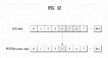
- FIG. 12 illustrates a structure for determining a PUCCH for ACK/NACK transmission, to which the present invention is applied.
- a PUCCH that will carry ACK/NACK information is not allocated to a UE in advance. Rather, a plurality of PUCCHs is used separately at each time instant by a plurality of UEs within a cell. Specifically, a PUCCH that a UE will use to transmit ACK/NACK information is implicitly determined on the basis of a PDCCH carrying scheduling information for a PDSCH that delivers downlink data.
- An entire area carrying PDCCHs in a downlink subframe includes a plurality of control channel elements (CCEs) and a PDCCH transmitted to a UE includes one or more CCEs.
- a CCE includes a plurality of (e.g. 9) resource element groups (REGs).
- One REG includes four contiguous REs except for an RS.
- the UE transmits ACK/NACK information on an implicit PUCCH that is derived or calculated by a function of a specific CCE index (e.g. the first or lowest CCE index) from among the indexes of CCEs included in a received PDCCH.
- a specific CCE index e.g. the first or lowest CCE index
- the lowest CCE index of a PDCCH corresponds to a PUCCH resource index for ACK/NACK transmission.
- the UE on the assumption that a PDCCH including CCEs #4, #5 and #6 delivers scheduling information for a PDSCH to a UE, the UE transmits an ACK/NACK to a BS on a PUCCH, for example, PUCCH #4 derived or calculated using the lowest CCE index of the PDCCH, CCE index 4.
- n 1 PUCCH n CCE + N 1 PUCCH
- n (1) PUCCH denotes the index of a PUCCH resource for transmitting ACK/NACK information
- N (1) PUCCH denotes a signal value received from a higher layer
- n CCE denotes the lowest of CCE indexes used for transmission of a PDCCH.
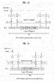
- FIGS. 13 and 14 illustrate slot-level structures of PUCCH Formats 1a and 1b for ACK/NACK transmission.
- FIG. 13 illustrates PUCCH Formats 1a and 1b in case of a normal CP and FIG. 14 illustrates PUCCH Formats 1a and 1b in case of an extended CP.
- the same UCI is repeated on a slot basis in a subframe in PUCCH Format 1a and 1b.
- a UE transmits an ACK/NACK signal in the resources of a different cyclic shift (CS) (a frequency-domain code) of a computer-generated constant amplitude zero auto correlation (CG-CAZAC) sequence and an orthogonal cover (OC) or orthogonal cover code (OCC) (a time-domain spreading code).
- CS cyclic shift
- CG-CAZAC computer-generated constant amplitude zero auto correlation
- OCC orthogonal cover code
- the OC includes, for example, a Walsh/DFT orthogonal code.
- PUCCH Format 1 for transmitting SR information is the same as PUCCH Formats 1a and 1b in terms of slot-level structure and different from PUCCH Formats 1a and 1b in terms of modulation.
- PUCCH resources composed of a CS, an OC, and a physical resource block (PRB) may be allocated to a UE by radio resource control (RRC) signaling, for transmission of SR information and an ACK/NACK for semi-persistent scheduling (SPS).
- RRC radio resource control
- SPS semi-persistent scheduling
- PUCCH resources may be indicated to a UE implicitly using the lowest CCE index of a PDCCH corresponding to a PDSCH or the lowest CCE index of a PDCCH for SPS release, for dynamic ACK/NACK (or an ACK/NACK for non-persistent scheduling) feedback or ACK/NACK feedback for a PDCCH indicating SPS release.
- FIG. 15 illustrates PUCCH Format 2/2a/2b in case of a normal CP
- FIG. 16 illustrates PUCCH Format 2/2a/2b in case of an extended CP.
- one subframe includes 10 QPSK symbols except for an RS symbol in case of a normal CP.
- Each QPSK symbol is spread with a CS in the frequency domain and then mapped to a corresponding SC-FDMA symbol.
- SC-FDMA symbol-level CS hopping may be used to randomize inter-cell interference.
- An RS may be code division multiplexed (CDM) using a CS. For example, if there are 12 or 6 available CSs, 12 or 6 UEs may be multiplexed in the same PRB. That is, a plurality of UEs may be multiplexed using CS+OC+PRB and CS+PRB in PUCCH Formats 1/1a/1b and 2/2a/2b.
- CDM code division multiplexed
- OCs of length 4 or length 3 for PUCCH Format 1/1a/1b are illustrated in Table 4 and Table 5 below.
- Table 4 Sequence Index Orthogonal sequence 0 [+1 +1 +1 +1] 1 [+1 -1 +1 -1] 2 [+1 -1 -1 +1]
- Table 5 Sequence Index Orthogonal sequence 0 [1 1 1] 1 [1 e j2 ⁇ /3 e j4 ⁇ /3 ] 2 [1 e j4 ⁇ /3 e j2 ⁇ /3 ]
- FIG. 17 illustrates ACK/NACK channelization for PUCCH Formats 1a and 1b.
- ⁇ shift PUCCH 2.
- FIG. 18 illustrates channelization for a hybrid structure of PUCCH Format 1/1a/1b and PUCCH Format 2/2a/2b in the same PRB.
- CS hopping and OC re-mapping may be performed as follows.
- resources n r for PUCCH Format 1/1a/1b include the following combinations.
- n cs n oc , n rb .
- a combination of an ACK/NACK and a CQI, PMI, RI and CQI may be delivered in PUCCH Format 2/2a/2b.
- Reed Muller (RM) channel coding may be applied.
- channel coding for an uplink CQI is described as follows in the LTE system.
- a bit stream ⁇ 0 , ⁇ 1 , ⁇ 2 , ⁇ 3 ,..., ⁇ A-1 is channel-encoded with a (20, A) RM code.
- Table 7 lists base sequences for the (20, A) code.
- ⁇ 0 and ⁇ A-1 are the Most Significant Bit (MS) and Least Significant Bit (LSB), respectively.
- MS Most Significant Bit
- LSB Least Significant Bit
- a bit stream may be encoded to 20 bits by an RM code and then modulated in QPSK. Before QPSK modulation, the coded bits may be scrambled.
- Channel-coded bits b 0 , b 1 , b 2 , b 3 ,. . ., b B-1 may be generated by Equation 2.
- i 0, 1, 2, . . ., B-1.
- Table 8 illustrates a UCI field for feedback of a broadband report (a single antenna port, transmit diversity, or open loop spatial multiplexing PDSCH) CQI.
- a broadband report (a single antenna port, transmit diversity, or open loop spatial multiplexing PDSCH) CQI.
- Table 8 Field Bandwidth Broadband CQI 4
- Table 9 illustrates a UCI field for feedback of a broadband CQI and a PMI. This field reports transmission of a closed loop spatial multiplexing PDSCH.
- Table 10 illustrates a UCI field to feedback an RI for a broadband report.
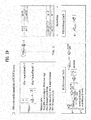
- FIG. 19 illustrates PRB allocation.
- a PRB may be used to carry a PUCCH in slot n s .
- a multi-carrier system or carrier aggregation (CA) system is a system using a plurality of carriers each having a narrower bandwidth than a target bandwidth in order to support broadband.
- the bandwidth of each of the aggregated carriers may be limited to a bandwidth used in a legacy system in order to ensure backward compatibility with the legacy system.
- the legacy LTE system supports 1.4, 3, 5, 10, 15, and 20MHz and the LTE-A system evolved from the LTE system may support a broader bandwidth than 20MHz using only bandwidths supported by the LTE system.
- CA may be supported by defining a new bandwidth irrespective of the bandwidths used in the legacy system.
- the term multi-carrier is used interchangeably with CA and spectrum aggregation.
- CA covers both contiguous CA and non-contiguous CA.
- CA my cover both intra-band CA and inter-band CA.
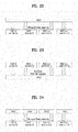
- FIG. 20 is a conceptual view illustrating DL CC management at a BS and FIG. 21 illustrates a conceptual view illustrating UL CC management at a UE.
- a higher layer will be referred simply as a MAC layer in FIGS. 19 and 20 .
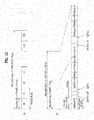
- FIG. 22 is a conceptual view illustrating multi-carrier management of one MAC layer at a BS and FIG. 23 is a conceptual view illustrating multi-carrier management of one MAC layer at a UE.
- one MAC layer performs transmission and reception by managing and operating one or more frequency carriers. Because the frequency carriers managed by the single MAC layer do not need to be contiguous, this multi-carrier management scheme is more flexible in terms of resource management.
- one physical (PHY) layer refers to one CC, for convenience.
- a PHY layer is not necessarily an independent radio frequency (RF) device. While one independent RF device generally corresponds to one PHY layer, it may include a plurality of PHY layers.
- RF radio frequency
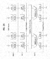
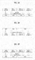
- FIG. 24 is a conceptual view illustrating multi-carrier management of a plurality of MAC layers at a BS
- FIG. 25 is a conceptual view illustrating multi-carrier management of a plurality of MAC layers at a UE
- FIG. 26 is another conceptual view illustrating multi-carrier management of a plurality of MAC layers at a BS
- FIG. 27 is another conceptual view illustrating multi-carrier management of a plurality of MAC layers at a UE.
- a plurality of MAC layers may control a plurality of carriers, as illustrated in FIGS. 24 to 27 .
- Each MAC layer may control one carrier in a one-to-one correspondence as illustrated in FIGS. 24 and 25 , whereas each MAC layer may control one carrier in a one-to-one correspondence, for some carriers and one MAC layer may control one or more of the remaining carriers as illustrated in FIGS. 26 and 27 .
- the above-described system uses a plurality of carriers, that is, first to N-th carriers, and the carriers may be contiguous or non-contiguous irrespective of downlink or uplink.
- a TDD system is configured to use N carriers such that downlink transmission and uplink transmission take place on each carrier, whereas an FDD system is configured to use a plurality of carriers for each of downlink transmission and uplink transmission.
- the FDD system may support asymmetrical CA in which different numbers of carriers and/or carriers having different bandwidths are aggregated for downlink and uplink.
- CCs When the same number of CCs is aggregated for downlink and uplink, all CCs can be configured with backward compatibility with the legacy system. However, CCs without backward compatibility are not excluded from the present invention.
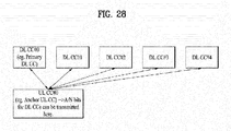
- FIG. 28 illustrates exemplary asymmetrical CA in which five DL CCs are linked to a single UL CC.
- This asymmetrical CA may be set from the perspective of transmitting UCI.
- Specific UCI e.g. ACK/NACK responses
- specific UCI e.g. ACKs/NACKs for DL CCs
- a predetermined UL CC e.g., primary CC, primary cell or PCell.
- each DL CC can carry up to two codewords and the number of ACKs/NACKs for each CC depends on the maximum number of codewords set per CC (for example, if a BS sets up to two codewords for a specific CC, even though a specific PDCCH uses only one codeword on the CC, two ACKs/NACKs are set for the CC), at least two UL ACK/NACK bits are needed for each DL CC. In this case, to transmit ACKs/NACKs for data received on five DL CCs on a single UL CC, at least ten ACK/NACK bits are needed.
- transmission of CQI/PMI/RI information related to a plurality of DL CCs may increase UCI payload.
- ACK/NACK information related to codewords is described in the present invention by way of example, it is obviously to be understood that a transport block corresponding to a codeword exists and the same is applicable to ACK/NACK information for transport blocks.
- a UL anchor CC (a UL PCC or a UL primary CC) is a CC that delivers a PUCCH or UCI, determined cell-specifically/UE-specifically. For example, a UE can determine a CC for which initial random access is attempted as the primary CC. A DTX state may be fed back explicitly or may be fed back so as to share the same state with a NACK.
- a cell is defined as a combination of downlink resources and uplink resources. Yet, the uplink resources are not mandatory. Therefore, a cell may be composed of downlink resources only or both downlink resources and uplink resources.
- the linkage between the carrier frequencies (or DL CCs) of downlink resources and the carrier frequencies (or UL CCs) of uplink resources may be indicated by system information.
- a cell operating in primary frequency resources (or a PCC) may be referred to as a primary cell (PCell) and a cell operating in secondary frequency resources (or an SCC) may be referred to as a secondary cell (SCell).
- PCell primary cell
- SCell secondary cell
- the PCell is used for a UE to establish an initial connection or re-establish a connection.
- the PCell may refer to a cell indicated during handover. Only one PCell can exist during CA in LTE-A release 10.
- the SCell may be configured after an RRC connection is established and may be used to provide additional radio resources.
- the PCell and the SCell may collectively be referred to as a serving cell. Accordingly, a single serving cell composed of a PCell only exists for a UE in RRC_Connected state, for which CA is not set or which does not support CA. On the other hand, one or more serving cells exist, including a PCell and entire SCells, for a UE in RRC_CONNECTED state, for which CA is set.
- a network may configure one or more SCells in addition to an initially configured PCell, for a UE supporting CA during connection setup after an initial security activation operation is initiated. Therefore, PCC is interchangeably used with PCell, primary (radio) resources, and primary frequency resources. Similarly, SCC is used interchangeably with SCell, secondary (radio) resources, and secondary frequency resources.
- the new PUCCH format proposed by the present invention is called CA PUCCH Format or PUCCH Format 3, considering that PUCCH Format 1 to PUCCH Format 2 are defined in legacy LTE Release 8/9.
- the technical features of the proposed PUCCH format may be applied to any physical channel (e.g. a PUSCH) that can deliver UCI in the same manner or in a similar manner.
- a PUSCH physical channel
- an embodiment of the present invention is applicable to a periodic PUSCH structure for transmitting control information periodically or a non-periodic PUSCH structure for transmitting control information non-periodically.
- the UCI/RS symbol structure of the legacy LTE PUCCH Format 1/1a/1b (in case of a normal CP) is used as a subframe-level/slot-level UCI/RS symbol structure applied to PUCCH Format 3.
- the subframe-level/slot-level UCI/RS symbol structure of PUCCH Format 3 is defined to provide an example, which should not be construed as limiting the present invention.
- the number and positions of UCI/RS symbols may be changed freely in PUCCH Format 3 of the present invention according to system design.
- PUCCH Format 3 according to an embodiment of the present invention may be defined using the RS symbol structure of the legacy LTE PUCCH Format 2/2a/2b.
- PUCCH Format 3 may be used to transmit UCI of any type/size.
- information such as HARQ ACK/NACK, CQI, PMI, RI, and SR may be transmitted in PUCCH Format 3 according to the embodiment of the present invention.
- This information may have a payload of any size.
- the following description will focus on transmission of ACK/NACK information in PUCCH Format 3 according to the present invention.
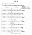
- FIGS. 29 to 32 illustrate the structure of PUCCH Format 3 that can be used in the present invention and a signal processing operation for PUCCH Format 3.
- FIGS. 29 to 32 illustrate a DFT-based PUCCH format.
- a PUCCH is DFT-precoded and spread with a time-domain OC at an SC-FDMA level, prior to transmission.
- the DFT-based PUCCH format will be referred to as PUCCH Format 3.
- a channel coding block channel-encodes transmission bits a_0, a_1, ..., a_M-1 (e.g. multiple ACK/NACK bits), thus creating coded bits (or a codeword), b_0, b_1, ..., b_N-1.
- M is the size of transmission bits
- N is the size of coded bits.
- the transmission bits include UCI, for example, multiple ACKs/NACKs for a plurality of data (or PDSCHs) received on a plurality of DL CCs.
- the transmission bits a_0, a_1, ..., a_M-1 are jointly encoded irrespective of the type, number, or size of UCI that forms the transmission bits.
- the transmission bits include multiple ACKs/NACKs for a plurality of DL CCs
- channel coding is performed on the entire bit information, rather than per DL CC or per ACK/NACK bit.
- a single codeword is generated by channel coding.
- Channel coding includes, without being limited to, repetition, simplex coding, RM coding, punctured RM coding, tail-biting convolutional coding (TBCC), low-density parity-check (LDPC) coding, or turbo coding.
- the coded bits may be rate-matched, taking into account modulation order and the amount of resources.
- the rate matching function may be incorporated into the channel coding block or implemented in a separate functional block.
- the channel coding block may produce a single codeword by performing (32, 0) RM coding on a plurality of pieces of control information and may subject the single codeword to cyclic buffer rate-matching.
- a modulator generates modulation symbols c_0, c_1, ..., c_L-1 by modulating the coded bits b_0, b_1, . . ., b_M-1.
- L is the size of modulation symbols.
- a modulation scheme is performed by changing the amplitude and phase of a transmission signal.
- the modulation scheme may be n-phase shift keying (n-PSK) or n-quadrature amplitude modulation (QAM) (n being 2 or a larger integer). More specifically, the modulation scheme may be BPSK, QPSK, 8-PSK, QAM, 16-QAM, or 64-QAM.
- a divider divides the modulation symbols c_0, c_1, ..., c_L-1 into slots.
- the order/pattern/scheme of dividing modulation symbols into slots is not limited to a specific one.
- the divider may divide the modulation symbols into slots, sequentially starting from the first modulation symbol (localized scheme).
- the modulation symbols c_0, c_1, ..., c_L/2-1 may be allocated to slot 0 and the modulation symbols c_L/2, c_L/2+1, ..., c_L-1 may be allocated to slot 1.
- the modulation symbols When the modulation symbols are allocated to the slots, they may be interleaved (or permuted). For example, even-numbered modulation symbols may be allocated to slot 0 and odd-numbered modulation symbols may be allocated to slot 1. Division may precede modulation.
- a DFT precoder performs DFT precoding (e.g. 12-point DFT) on the modulation symbols allocated to the slots in order to generate a single carrier waveform.
- DFT precoding e.g. 12-point DFT
- the modulation symbols c_0, c_1, ..., c_L/2-1 allocated to slot 0 are DFT-precoded to d_0, d_1, ..., d_L/2-1
- the modulation symbols c_L/2, c_L/2+1, ..., c_L-1 allocated to slot 1 are DFT-precoded to d_L/2, d_L/2+1, ..., d_L-1.
- DFT precoding may be replaced with another linear operation (e.g. Walsh precoding).
- a spreading block spreads DFT signals at an SC-FDMA symbol level (in the time domain).
- the SC-FDMA symbol-level time-domain spreading is performed using a spreading code (sequence).
- the spreading code includes a quasi-orthogonal code and an orthogonal code.
- the quasi-orthogonal code includes, without being limited to, a PN (pseudo noise) code.
- the orthogonal code includes, without being limited to, a Walsh code and a DFT code. While an orthogonal code is taken as a main example of the spreading code herein for convenience, the orthogonal code may be replaced with a quasi-orthogonal code.
- the maximum value of a spreading code size is limited by the number of SC-FDMA symbols used to transmit control information. For example, if four SC-FDMA symbols cany control information in one slot, an orthogonal code of length 4, w0, w1, w2, w3 can be used in each slot.
- the SF means the degree to which control information is spread.
- the SF may be related to the multiplexing order or antenna multiplexing order of a UE.
- the SF may be changed to 1, 2, 3, 4, ... depending on system requirements.
- An SF may be predefined between a BS and a UE or the BS may indicate an SF to the UE by DCI or RRC signaling.
- a signal generated from the above operation is mapped to subcarriers in a PRB and converted to a time-domain signal by IFFT.
- a CP is added to the time-domain signal and the resulting SC-FDMA symbols are transmitted through an RF end.
- ACK/NACK bits for the PDSCHs may be 12 bits, including a DTX state.
- the size of a coding block (after rate matching) may be 48 bits.
- the coded bits are modulated to 24 QPSK symbols and the QPSK symbols are divided into two slots, 12 QPSK symbols for each slot.
- a spreading block may be generated in advance at the front end of a DFT precoder.
- RSs may be configured in the same configuration as used in the LTE system.
- a base sequence may be cyclically shifted.
- the multiplexing capacity of an RS part is determined by a CS interval ⁇ shift PUCCH .
- the multiplexing capacity of the RS part is 4 in case of ⁇ shift PUCCH . Therefore, overall multiplexing capacity may be limited to the smaller of the two values, 4.
- FIG. 31 illustrates an exemplary structure of PUCCH Format 3 that can increase a multiplexing capacity at a slot level.
- Overall multiplexing capacity can be increased by applying SC-FDMA symbol-level spreading described with reference to FIGS. 29 and 30 to RSs.
- the multiplexing capacity is doubled by applying a Walsh cover (or a DFT code cover) within a slot.
- the multiplexing capacity is 8 even in case of ⁇ shift PUCCH , thereby preventing a decrease in the multiplexing capacity of a data part.
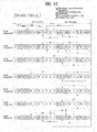
- FIG. 32 illustrates an exemplary structure of PUCCH Format 3 that can increase a multiplexing capacity at a subframe level.
- PUCCH Format 3 is not limited to the orders illustrated in FIGS. 29 to 32 .
- FIG. 33 illustrates an ACK/NACK information transmission structure using channel selection to which the present invention is applied.
- two PUCCH resources or PUCCH channels (PUCCH resources #0 and #1 or PUCCH channels #0 and #1) can be set for PUCCH format 1b for 2-bit ACK/NACK information.
- 3-bit ACK/NACK information is transmitted, 2 bits of the 3-bit ACK/NACK information can be represented according to PUCCH format 1b and the remaining 1 bit can be represented according to which one of the two PUCCH resources is selected. For example, 1 bit (2 cases) can be represented by selecting transmission of the ACK/NACK information using PUCCH resource #0 or transmission of the ACK/NACK information using PUCCH resource #1. In this manner, the 3-bit ACK/NACK information can be represented.
- Table 11 shows an example of transmission of 3-bit ACK/NACK information using channel selection on the assumption that two PUCCH resources are set.
- ACK/NACK Ch1 Ch2 RS Data RS Data N,N,N 1 1 1 0 0 N,N,A 1 -j 0 0 N,A,N 1 j 0 0 N,A,A 1 -1 0 0 A,N,N 0 0 1 1 A,N,A 0 0 1 -j A,A,N 0 0 1 j A,A,A 0 0 1 1 1
- 'A' denotes ACK information and 'N' denotes NACK information or NACK/DTX information.
- '1, -1, j and -j' represent four complex modulated symbols obtained by modulating 2 bits of information, b(0)b(1), transmitted in a PUCCH format, according to QPSK.
- b(0)b(1) correspond binary bits transmitted using a selected PUCCH resource.
- b(0)b(1) can be mapped to a complex modulated symbol and transmitted through a PUCCH resource.
- FIG. 34 illustrates an ACK/NACK information transmission structure using enhanced channel selection to which the present invention is applied. While FIG. 34 shows that PUCCH #0 and PUCCH #1 correspond to different time/frequency regions, PUCCH #0 and PUCCH #1 can be configured to use different codes in the same time/frequency region. Referring to FIG. 34 , two PUCCH resources (PUCCH resources #0 and #1) can be set for PUCCH format 1a for 1-bit ACK/NACK information transmission.
- ACK/NACK information If 3-bit ACK/NACK information is transmitted, 1 bit thereof can be represented using PUCCH format 1a and another 1 bit can be represented according to which one of the PUCCH resources (PUCCH resources #0 and #1) is used to transmit the ACK/NACK information. The remaining 1 bit can be represented based on a reference signal corresponding to a corresponding PUCCH resource. While the reference signal is preferably transmitted in the time/frequency region corresponding to a PUCCH resource (PUCCH resource #0 or #1) selected first, the reference signal may be transmitted in a time/frequency region with respect to the PUCCH resource corresponding thereto.
- 2 bits (4 cases) can be represented by selecting one of a case in which the ACK/NACK information is transmitted through PUCCH resource #0 and a reference signal corresponding to PUCCH resource #0 is transmitted, a case in which the ACK/NACK information is transmitted through PUCCH resource #1 and a reference signal corresponding to PUCCH resource #1 is transmitted, a case in which the ACK/NACK information is transmitted through PUCCH resource #0 and a reference signal corresponding to PUCCH resource #1 is transmitted, and a case in which the ACK/NACK information is transmitted through PUCCH resource #1 and a reference signal corresponding to PUCCH resource #0 is transmitted.
- the 3-bit ACK/NACK information can be represented.
- Table 13 shows an example of transmission of 3-bit ACK/NACK information using enhanced channel selection on the assumption that two PUCCH resources are set.
- ACK/NACK Ch1 Ch2 RS Data RS Data N,N,N 1 1 0 0 N,N,A 1 -1 0 0 N,A,N 0 1 1 0 N,A,A 0 -1 1 0 A,N,N 1 0 0 1 A,N,A 1 0 0 -1 A,A,N 0 0 1 1 A,A,A 0 0 1 -1
- symbols mapped to PUCCH resources can be obtained according to BPSK, distinguished from ACK/NACK information transmission using channel selection, shown in Table 12.
- complex symbols can be obtained according to QPSK using PUCCH format 1b, differently from the example of FIG. 13 . In this case, the number of bits that can be transmitted through the same PUCCH resource can be increased.
- FIGS. 33 and 34 illustrate a case in which two PUCCH resources are set for 3-bit ACK/NACK information transmission
- the number of bits of transmitted ACK/NACK information and the number of PUCCH resources can be varied.
- the ACK/NACK information transmission structures can be equally applied to transmission of uplink control information other than ACK/NACK information or simultaneous transmission of ACK/NACK information and uplink control information.
- Table 14 shows an example of transmission of six ACK/NACK states using channel selection when two PUCCH resources are set.
- HARQ-ACK(O), HARQ-ACK(1) n (1) PUCCH b(0),b(1) ACK, ACK n (1) PUCCH,1 1,1 ACK, NACK/DTX n (1) PUCCH,0 0,1 NACK/DTX, ACK n (1) PUCCH,1 0,0 NACK/DTX, NACK n (1) PUCCH,1 1,0 NACK, DTX n (1) PUCCH,0 1,0 DTX, DTX N/A N/A
- Table 15 shows an example of transmission of eleven ACK/NACK states using channel selection when three PUCCH resources are set.
- HARQ-ACK(O), HARQ-ACK(1), HARQ-ACK(2) n (1) PUCCH b(0),b(1) ACK, ACK, ACK n (1) PUCCH,2 1,1 ACK, ACK, NACK/DTX n (1) PUCCH,1 1,1 ACK, NACK/DTX, ACK n (1) PUCCH,0 1,1 ACK, NACK/DTX, NACK/DTX n (1) PUCCH,0 0,1 NACK/DTX, ACK, ACK n (1) PUCCH,2 1,0 NACK/DTX, ACK, NACK/DTX n (1) PUCCH,1 0,0 NACK/DTX, NACK/DTX, ACK n (1) PUCCH,2 0,0 DTX, DTX, NACK n (1) PUCCH,2 0,0 DTX, DTX, NACK n (1) PUCCH,2 0,
- Table 16 shows an example of transmission of twenty ACK/NACK states using channel selection when four PUCCH resources are set.
- ACK, NACK/DTX n PUCCH,1 1,0 NACK/DTX, NACK/DTX, NACK, DTX n (1) PUCCH,2 1,1 ACK, ACK, NACK/DTX, ACK n (1) PUCCH,1 1,0 NACK, DTX, DTX, DTX n (1) PUCCH,0 1,0 ACK, ACK, NACK/DTX, NACK/DTX n (1) PUCCH,1 1,0 ACK, NACK/DTX, ACK, ACK n (1) PUCCH,3 0,1 NACK/DTX, NACK/DTX, NACK/DTX, NACK n (1) PUCCH,3 1,1 ACK, NACK/DTX, ACK, NACK/DTX n (1) PUCCH,2 0,1 ACK, NACK/DTX, NACK/DTX, ACK n (1) PUCCH,0 0,1 ACK, NACK/DTX, NACK/DTX, NACK/DTX n (1) PUCCH
- a UE collects responses to cases that require a plurality of ACK/NACK feedbacks received from a PCell DL CC and SCell DL CCs (through multiplexing, bundling, etc., for example) and transmits the responses using a PUCCH in a UL CC in a PCell.
- Cases that require HARQ ACK/NACK feedback for a DL CC can include the following three.
- HARQ ACK/NACK feedback can be required in the case of Table 17.
- Table 17 For a PDSCH(s) transmission indicated by the detection of a corresponding PDCCH(s) in subframe(s) n-k, where k ⁇ K and K is a set of M elements ⁇ k 0 , k 1 , ⁇ k M -1 ⁇ depending on the subframe n and the UL-DL configuration.
- Table 17 represents a PDSCH(s) that requires normal A/N feedback.
- the PDSCH can be present in DL PCell and SCells. This PDSCH is called 'PDSCH with PDCCH' in the following description for convenience.
- HARQ ACK/NACK feedback can be required in the case of Table 18.
- Table 18 For a PDCCH(s) indicating downlink SPS release in subframe(s) n - k , where k ⁇ K and K is a set of M elements ⁇ k 0 , k 1 , ⁇ k M -1 ⁇ depending on the subframe n and the UL-DL configuration.
- Table 18 represents A/N feedback for PDCCH(s) for SPS release.
- only one PDSCH without corresponding PDCCH can be present over one or more DL cells in one subframe.
- A/N feedback for PDCCH(s) indicating DL SPS (semi-persistent scheduling) release may be performed whereas A/N feedback for PDCCH(s) indicating DL SPS activation may not be performed.
- This PDCCH can be present only in a DL PCell. This case is referred to as 'DL SPS release' in the following description for convenience.
- HARQ ACK/NACK feedback can be required in the case of Table 19.
- Table 19 For a PDSCH(s) transmission where there is not a corresponding PDCCH detected in subframe(s) n-k , where k ⁇ K and K is a set of M elements ⁇ k 0 , k 1 , ⁇ k M -1 ⁇ depending on the subframe n and the UL-DL configuration.
- Table 19 represents A/N feedback for PDSCH(s) without PDCCH(s) indicating SPS. Only one PDSCH without corresponding PDCCH can be present over one or more DL cells in one subframe. This PDSCH can be present only in a DL PCell. This case is referred to as 'DL SPS' in the following description for convenience.
- HARQ ACK/NACK feedback events described using Tables 17, 18 and 19 are exemplary and HARQ ACK/NACK feedback may be performed when other events are generated.
- M denotes the number of elements of a set K and HARQ-ACK transmission timing for DL reception and K can be represented according to subframe position (n) and TDD UL-DL configuration, as shown in Table 20.
- Table 20 UL-DL Configuration Subframe n 0 1 2 3 4 5 6 7 8 9 0 - - 6 - 4 - - 6 - 4 1 - - 7, 6 4 - - - 7, 6 4 - 2 - - 8, 7, 4, 6 - - - - 8, 7, 4, 6 - - 3 - - 7, 6, 11 6, 5 5,4 - - - - - 4 - 12, 8, 7, 11 6, 5, 4, 7 - - - - - - 5 - - 13, 12, 9, 8, 7, 5, 4, 11, 6 - - - - - - 6 - - 7 7 5 - - 7 7 - - 7 - - 7 -
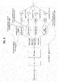
- Table 20 can be represented as FIG. 35 or 37 .
- FIGS. 35 and 37 illustrate ACK/NACK feedback for DL subframes according to Table 20 when ACK/NACK feedback is performed in UL subframes in the second of two frames.
- ACK/NACK for a special subframe (of the first frame) corresponding to the sixth subframe from the first UL subframe is fed back.
- the second UL subframe of the second frame no ACK/NACK is fed back.
- ACK/NACK for a DL subframe corresponding to the fourth subframe from the third UL subframe and being prior to the third UL subframe is fed back.
- ACK/NACK for a special subframe corresponding to the sixth subframe from the fourth UL subframe and being prior to the fourth UL subframe is fed back.
- no ACK/NACK is fed back.
- ACK/NACK for a DL subframe corresponding to the fourth subframe from the sixth UL subframe and being prior to the sixth UL subframe is fed back.
- ACK/NACK for a DL subframe (of the first frame), which is the seventh one from the first UL subframe, and ACK/NACK for a special subframe (of the first frame), which is the sixth one from the first UL subframe, are multiplexed or bundled and fed back.
- ACK/NACK for a DL subframe (of the first frame), which is the fourth one from the second UL subframe is fed back.
- ACK/NACK for a DL subframe which is the seventh one from the third UL subframe
- ACK/NACK for a special subframe which is the sixth one from the third UL subframe
- ACK/NACK for a special subframe which is the sixth one from the third UL subframe
- ACK/NACK for a DL subframe which is the fourth subframe from the fourth UL subframe
- ACK/NACK feedback is performed in the same manner as in UL-DL configurations #0 and #1.
- the position of a DL subframe corresponding to ACK/NACK fed back in each UL subframe depends on TDD UL-DL configuration and UL subframe position in TDD.
- cross-scheduling from a PCell to an SCell(s) may be supported whereas cross-scheduling from the SCell(s) to the PCell may not be supported.
- additional PDSCH allocation may not be performed in the cell(s). That is, a specific cell can be cross-scheduled only from a specific cell.
- Cross-carrier scheduling is a scheme in which a control channel transmitted through a primary CC schedules a data channel transmitted through the primary CC or another CC using a carrier indicator field (CIF).
- CIF carrier indicator field
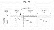
- FIG. 36 illustrates cross-carrier scheduling.
- the number of cells (or CCs) allocated to a relay node is 3 and cross-carrier scheduling is performed using the CIF as described above.
- DL cell (or DL CC) #A is assumed as a primary DL CC (i.e. primary cell; PCell) and other CCs #B and #C are assumed as secondary CCs (i.e. secondary cells; SCells).
- a UE is configured to performed communication through two CCs in the following.
- PCell primary CC
- SCC secondary CC
- the UE receives various control signals including a PDCCH through the PCell and data transmission and reception of the SCell is cross-carrier scheduled according to a control signal in the PCell.
- CC #1 DL PCell, LTE-A frequency band
- CC #3 UL PCell, LTE-A frequency band
- SCell unlicensed band
- Intra-band CA is considered first for a CA environment, in general.
- a band used in intra-band and inter-band refers to an operating band and can be defined as follows.
- the operating band represents a frequency range in E-UTRA operating in a paired or unpaired manner and can be defined as a specific set according to technical requirements.
- operating bands used in LTE can be defined as shown in Table 21.
- E-UTRA Operating Band Uplink (UL) operating band BS receive UE transmit Downlink (DL) operating band BS transmit UE receive Duplex Mode F UL_low - F UL_high F DL_low - F DL_high 1 1920 MHz - 1980 MHz 2110 MHz - 2170 MHz FDD 2 1850 MHz - 1910 MHz 1930MHz - 1990 MHz FDD 3 1710 MHz - 1785 MHz 1805MHz - 1880 MHz FDD 4 1710 MHz - 1755 MHz 2110MHz - 2155 MHz FDD 5 824 MHz - 849 MHz 869 MHz - 894MHz FDD 6 1 830 MHz - 840 MHz 875 MHz - 885 MHz FDD 7 2500 MHz - 2570 MHz 2620MHz - 2690 MHz FDD 8 880 MHz - 915 MHz 925 MHz - 960 MHz F
- Intra-band CA refers to positioning of a plurality of DL CCs and/or UL CCs in the frequency domain in a contiguous or non-contiguous manner.
- intra-band CA can refer to positioning of carrier frequencies of a plurality of DL CCs and/or UL CCs in the same (operating) band.
- a plurality of CCs can be designed on the assumption that the CCs have similar propagation characteristics through intra-band CA.
- the propagation characteristics include propagation/path delay, propagation/path loss, fading channel impact, etc. depending on frequency (or center frequency).
- the UE sets uplink transmission timing for a primary cell UL CC.
- Uplink transmission timing for the secondary cell corresponds to uplink transmission timing for the primary cell on the above assumption (that CCs have similar propagation/path delays).
- PRACH physical random access channel
- inter-cell UL subframe boundaries in the UE can be adjusted to correspond to each other. Accordingly, the UE can perform communication in a CA environment using a single radio frequency (RF) terminal.
- RF radio frequency
- one or more cells may not be contiguous to other cells in the frequency domain in a CA environment because of problems with respect to frequency allocation to mobile carriers (allocation of remaining frequencies, reuse of frequencies previously used for other purposes, etc.) for mobile communication.
- the carrier frequency of one cell can be 800 MHz (UL/DL) and the carrier frequency of the other can be 2.5 GHz (UL/DL).
- the carrier frequency of one cell can be 800 MHz (UL/DL) and the carrier frequency of the other can be 2.6 GHz (UL/DL).
- the carrier frequency of one cell can be 700 MHz (UL/DL) and the carrier frequency of the other can be 1.7(UL)/2.1(DL) GHz (TDD).
- the carrier frequency refers to the carrier frequency of a DL CC or UL CC.
- inter-band CA An environment in which CCs are spaced apart in the frequency domain, as described above, can be referred to as inter-band CA.
- carrier frequencies of a plurality of DL CCs and/or UL CCs are present in different bands.
- inter-cell (UL) subframe boundaries are adjusted to correspond to each other in the inter-band CA environment. Accordingly, cells need different uplink transmission timings and the UE may use a plurality of RF terminals to perform communication in a CA environment.
- Time for detecting a PDSCH (with or without corresponding PDCCH) or PDCCH indicating DL SPS release, which corresponds to PUCCH transmission timing (n-th subframe), can be defined as follows.
- a HARQ-ACK response to a PDCCH or PDSCH indicating DL SPS release in subframe n -4 is transmitted through a PUCCH in subframe n in an FDD environment.
- HARQ-ACK responses to a PDCCH and/or PDSCH indicating DL SPS release in subframe n -4 are transmitted through a PUCCH in subframe n in a TDD environment.
- a single PUCCH can include HARQ-ACK responses to one or more PDCCHs and/or a PDSCHs indicating DL SPS release.
- the set K can be configured as shown in Table 20.
- a DAI (UL-DL configurations #1 to #6) in DCI format 1/1A/1B/1D/2/2A/2B/2C of a PDCCH can represent the accumulative number of PDCCHs with assigned PDSCH transmission in subframe n-k in each serving cell and a PDCCH indicating DL SPS release.
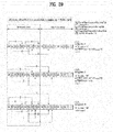
- FIG. 37 illustrates a PDSCH or a PDCCH in subframe n-k corresponding to PUCCH transmission in subframe n for DCI format 1/1A/1B/1D/2/2A/2B/2C.
- a single PUCCH can include HARQ-ACK responses to one or more PDCCHs and/or PUSCHs indicating DL SPS release.
- the set K can be configured as shown in Table 20.
- DCI format 0 or DCI format 4 detection time corresponding to PUSCH transmission time (n-th subframe) can be defined as follows.
- DCI format 0 or DCI format 4 in subframe n-k ' represents PUSCH allocation in subframe n in TDD.
- DAI V DAI UL (UL-DL configurations #1 to #6), represents the total number of subframes with PDCCH transmission with DCI format 0 or 4 and with PDCCH indicating downlink SPS release within subframe n-k'.
- Table 22 shows uplink information regarding index k' for TDD.
- FIG. 38 illustrates PDCCH subframe n-k' through which DCI format 0/4 for PUSCH allocation in subframe n is transmitted.
- PUSCH transmission time corresponding to PDCCH or PHICH detection time (n-th subframe) can be defined as follows.
- a PDCCH with DCI format 0 or DCI format 4 and/or PHICH transmission in subframe n are associated with a PUSCH in subframe n +4
- a PDCCH with DCI format 0 in subframe n and/or PHICH transmission in subframe n -5 are associated with the first PUSCH in subframe n +4.
- a PDCCH with a DCI format and/or PHICH transmission in subframe n are associated with a PUSCH in subframe n + k.
- a PDCCH with DCI format 0 in subframe n and/or PHICH transmission in subframe n-l are associated with the first PUSCH in subframe n + k.
- Table 23 shows the value k TDD configurations #0 to #6. [Table 23] TDD UL/DL Configuration subframe number n 0 1 2 3 4 5 6 7 8 9 0 4 6 4 6 1 6 4 6 4 2 4 4 3 4 4 4 4 4 5 4 6 7 7 7 5
- Table 23 shows the value k TDD configurations #0, #1 and #6.
- Table 24 TDD UL/DL Configuration subframe number n 0 1 2 3 4 5 6 7 8 9 0 9 6 9 6 1 2 3 2 3 6 5 5 6 6 8
- FIG. 39 illustrates subframe n + k to which a PUSCH is allocated when DCI format 0/4 or a PHICH for a normal HARQ operation is transmitted in subframe n.
- FIG. 40 illustrates transmission of a PUSCH in subframe n + k when a PHICH using subframe bundling is transmitted in subframe n-l in TDD UL/DL configuration #0 and transmission of a PUSCH in subframe n + k when DCI format 0/4 using subframe bundling is transmitted in subframe n.
- FIG. 41 illustrates transmission of a PUSCH in subframe n + k when a PHICH using subframe bundling is transmitted in subframe n-l in TDD UL/DL configurations #1 to #6 and transmission of a PUSCH in subframe n + k when DCI format 0/4 using subframe bundling is transmitted in subframe n.
- PHICH reception time corresponding to PUSCH transmission time (n-th subframe) can be defined as follows.
- a HARQ-ACK response to a PUSCH in subframe n is transmitted through a PHICH in subframe n + 4 in an FDD environment.
- a HARQ-ACK response to a PUSCH in subframe n is transmitted through a PHICH in subframe n + k PHICH in a TDD environment.
- Table 25 shows k PHICH in TDD. [Table 25] TDD UL/DL Configuration su bframe index n 0 1 2 3 4 5 6 7 8 9 0 4 7 6 4 7 6 1 4 6 4 6 2 6 6 3 6 6 6 4 6 6 5 6 6 4 6 6 4 7
- FIG. 42 illustrates transmission of a HARQ-ACK response to a PUSCH in subframe n through a PHICH in subframe n + k PHICH .
- PHICH reception time (n-th subframe) and PUSCH transmission time corresponding to the above response can be defined as follows.
- a HARQ-ACK response to a PUSCH in subframe i -4 is received through a PHICH in subframe i in an FDD environment.
- a HARQ-ACK response to a PUSCH in subframe i-k is received through a PHICH in subframe i in the case of TDD and UL/DL configurations #1 to #6.
- a HARQ-ACK response to a PUSCH in subframe i-k is received through a PHICH in subframe i in the case of TDD and UL/DL configuration #0.
- Table 26 shows k applied to TDD configurations #0 to #6.
- FIG. 43 shows that a HARQ-ACK response received through a PHICH in subframe i corresponds to a PUSCH in subframe i-k.
- a PDCCH carries a downlink control information (DCI) message.
- DCI downlink control information
- the DCI message can include resource allocation information and other control information.
- a plurality of PDCCHs is transmitted in subframes.
- Each PDCCH is transmitted using one or more control channel elements (CCEs) which correspond to nine sets of four physical resource elements in resource element groups (REGs).
- CCEs control channel elements
- REGs resource element groups
- REs mapped to reference symbols are not included in REGs, which means that the number of REGs corresponding to given OFDM symbols depends on whether or not cell-specific reference signals are present.
- REGs are applicable to other DCI (e.g. PCFICH, PHICH, etc.).
- PDCCH formats can be supported as shown in Table 27.
- Table 27 PDCCH format Number of CCEs(n) Number of REGs Number of PDCCH bits 0 1 9 72 1 2 18 144 2 4 36 288 3 8 72 576 1
- a PDCCH with a format consisting of n CCEs may only start with a CCE with a number equal to a multiple of n in order to simplify decoding operation.
- the number of CCEs used for transmission of a particular PDCCH is determined by the BS according to channel conditions.
- the PDCCH is intended for a UE with a good downlink channel, one CCE is likely to be sufficient. However, for a UE with a poor downlink channel, eight CCEs may be required in order to achieve sufficient robustness. Furthermore, the power level of a PDCCH may be adjusted to match the channel conditions.
- a set of CCE locations in which the UE may find PDCCHs thereof can be considered a search space.
- the search space has a different size for each PDCCH format.
- a dedicated search space (or UE-specific search space) and a common search space are present.
- the dedicated search space is configured individually per UE and the common search space is applicable to all UEs.
- the dedicated search space and the common search space may overlap for a given UE.
- the BS cannot find CCE resources to send PDCCHs to all UEs in a given subframe because information related to some allocated CCE locations is not present for a specific UE.
- a UE-specific hopping sequence can be applied to the starting position of the dedicated search space.
- the sizes of the dedicated search space and common search space are listed in Table 28. [Table 28] PDCCH format Number of CCEs(n) Number of candidates in common search space Number of candidates in dedicated search space 0 0 - 6 1 2 - 6 2 4 4 2 3 8 2 2
- the UE In order to control the computational load generated due to the total number of blind decoding attempts, the UE is not required to simultaneously search for all DCI formats.
- the UE always searches for formats 0 and 1A in the dedicated search space. Formats 0 and 1A have the same size and are distinguished by a flag in a message.
- the UE may be required to receive a further format (e.g. format 1, 1B or 2).
- a further format e.g. format 1, 1B or 2.
- the UE may be configured to search for formats 1A and 1C in the common search space.
- the UE may be configured to search for format 3 or 3A.
- Formats 3 and 3A which have the same size as formats 0 and 1A and may be distinguished by having CRC scrambled by a different identity.
- the UE to which carrier aggregation is not applied may be required to carry out a maximum of forty-four blind decoding operations in any subframe.
- a control region can consist of a set of CCEs, numbered from 0 to N CCE,k -1, where N CCE,k denotes the total number of CCEs in the control region of subframe k.
- a UE needs to monitor a set of PDCCH candidates for control information in every non-DRX subframe, where monitoring can imply attempting to decode each of the PDCCHs in the set according to all monitored DCI formats.
- the set of PDCCH candidates to be monitored can be defined in terms of search spaces.
- search space S k L at aggregation level L ⁇ ⁇ 1,2,4,8 ⁇ can be defined by a set of PDCCH candidates.
- CCEs corresponding to PDCCH candidates m of the search space S k L can be determined according to Equation 3.
- M ( L ) is the number of PDCCH candidates to monitor in a predetermined search space.
- the UE needs to monitor a UE-specific search space at aggregation levels 1, 2, 4 and 8 and a common search space at aggregation levels 4 and 8.
- the common search space and the UE-specific search space may overlap.
- Aggregation levels defining search spaces are listed in Table 29. DCI formats that need to be monitored by the UE depend on the configured transmission mode. [Table 29] Search space S k L Number of PDCCH candidates M (L) Type Aggregation level L Size [in CCEs] UE-specific 1 6 6 2 12 6 4 8 2 8 16 2 Common 4 16 4 8 16 2
- Heterogeneous networks can be implemented by placing low-power nodes throughout a macro-cell layout.
- Interference characteristics in a heterogeneous deployment are significantly different from those in a homogeneous deployment. This is described with reference to FIG. 44 .
- a home eNB may interfere with a macro UE with no access to a closed subscriber group (CGS) cell.
- CCS closed subscriber group
- a macro UE may cause severe interference towards the HeNB.
- a CGS UE may be interfered by another CSG HeNB.
- path-loss based cell association may improve the uplink at the cost of increasing downlink interference of non-macro UEs at the cell edge.
- a macro cell can cause severe interference to UEs served by a pico cell, especially, pico UEs at the edge of the serving pico cell.
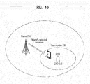
- the interfering macro cell provides a subframe, a so called Almost Blank subframe (ABS or ABS), protected from the dominant interference due to the macro cell.
- ABS Almost Blank subframe
- FIG. 45 illustrates an exemplary configuration of ABS in macro-pico scenarios.
- a macro cell for which subframes #2 and #6 are configured as ABSFs and information related thereto can be indicated to a pico cell via backhaul. Based on this information, the pico cell can schedule UEs corresponding thereto, especially UEs at the boundary of the macro cell and the pico cell.
- CSI measurement is only performed in the ABSFs. Otherwise, two types of subframes are configured for CSI measurement such that CSI measurement can be respectively performed in the normal subframe and ABSF.
- Dominant interference may occur when non-member UEs are in close proximity to a CSG cell.
- Time domain ICIC may be used to allow such non-member UEs to remain served by the macro cell on the same frequency layer.
- Such interference may be mitigated by the CSG cell utilizing almost blank subframes to protect subframes of the corresponding macro cell from the interference.
- a non-member UE may be signaled to utilize protected resources for cell measurements (RRM), radio link monitoring (RLM) and CSI measurements for the serving macro cell, allowing a UE to continue to be served by the macro cell under strong interference from the CSG cell.
- RRM cell measurements
- RLM radio link monitoring
- CSI measurements for the serving macro cell
- FIG. 46 illustrates an exemplary CSG scenario.
- Time domain ICIC may be utilized for pico UEs operating at the edge of a serving pico cell (e.g. for traffic off-loading from a macro cell to a pico cell).
- Time domain ICIC may be utilized to allow such UEs to remain served by the pico cell on the same frequency layer.
- Such interference may be mitigated by the macro cell utilizing almost blank subframes to protect the corresponding subframes of the pico cell from the interference.
- a UE served by a pico cell can use protected resources for cell measurements (RRM), radio link monitoring (RLM) and CSI measurements for the serving pico cell.
- RRM cell measurements
- RLM radio link monitoring
- CSI measurements for the serving pico cell.
- RRM/RLM/CSI measurement resource restriction may allow more accurate measurement of the pico cell under strong interference from the macro cell.
- the pico cell may selectively configure the RRM/RLM/CSI measurement resource restriction only for UEs subject to strong interference from the macro cell.
- the network may configure RRM measurement resource restriction for neighbour cells in order to facilitate mobility from the macro cell to the pico cell.
- FIG. 47 illustrates an example of the above-described pico scenario.
- An IE can provide information about which subframe is configured as an almost blank subframe by a BS and transmitted and which subset of almost blank subframes is configured for measurements for a UE.
- almost blank subframes correspond to subframes with reduced power on some physical channels and/or reduced activity.
- Table 30 shows ABS information.
- IE/Group Name Presence Range IE type and reference Semantics description CHOICE ABS Information M >FDD >>ABS Pattern Info M BIT STRING (SIZE(40)) Each position in the bitmap represents a subframe, for which value "1" indicates 'blanked in DL' and value "0" indicates 'not blanked in DL'.
- the ABS pattern is continuously repeated in all radio frames.
- the maximum number of subframes is 40.
- the maximum number of subframes is 20 for UL/DL subframe configuration 1 ⁇ 5;60 for UL/DL subframe configuration 6 ; 70 for UL/DL subframe configuration 0. UL/DL subframe configuration defined in TS 36.211 [10].
- the maximum number of subframes of an ABS pattern may be 20 for UL/DL subframe configurations #1 to #5, 60 for UL/DL subframe configuration #6 or 70 for UL/DL configuration #0.
- the ABS pattern is 20ms, 60ms or 70ms.
- an ABS can have periodicity of 20ms for UL/DL subframe configurations #1 to #5, 60ms for UL/DL subframe configuration #6 and 70ms for UL/DL configuration #0.
- ABS Status IE is used to aid the BS in designating ABS to evaluate the need for modification of the ABS pattern.
- Table 31 Information related thereto is shown in Table 31.
- DL ABS status M INTEGER (0..100) Percentage of resource blocks of ABS allocated for UEs protected by ABS from inter-cell interference. This includes resource blocks of ABS unusable due to other reasons. The denominator of the percentage calculation is indicated in the Usable ABS Information.
- SIZE(40) Each position in the bitmap represents a subframe, for which value "1" indicates 'ABS that has been designated as protected from inter - cell interference and value "0" indicates 'ABS that is not usable as protected ABS from inter-cell interference'.
- the pattern represented by the bitmap is a subset of, or the same as, the corresponding ABS Pattern InfdE conveyed in the LOAD INDICATION message. >TDD » Usable ABS Pattern Info M BIT STRING (1..70) Each position in the bitmap represents a subframe, for which value "1" indicates 'ABS that has been designated as protected from inter- cell interference' and value "0" indicates 'ABS that is not usable as protected ABS from inter- cell interference'.
- the pattern represented by the bitmap is a subset of, or the same as, the corresponding ABS Pattern Info IE conveyed in the LOAD INDICATION message.
- ABSs When ABSs are used, it is necessary to discriminate ABSs from non-ABSs when a UE measures RSRP (reference signal received power), RSRQ (reference signal received quality), etc. and performs radio link monitoring.
- RSRP reference signal received power
- RSRQ reference signal received quality
- ABSs when ABSs are used, the UE is required to perform measurement only in specific subframe sets (e.g. ABSs or non-ABSs) rather than all subframes.
- specific subframe sets e.g. ABSs or non-ABSs
- Time domain measurement resource restriction associated with ABSs is given in such a manner that an ABS pattern has 40 bits for FDD, 20 bits for TDD configurations #1 to #5, 70 bits for TDD configuration #0 and 60 bits for TDD configuration #6 and thus have periodicity of 40ms, 20ms, 70ms and 60ms.
- the UE can be configured with resource-restricted CSI measurement if subframe sets C CSI,0 and C CSI,1 are configured by higher layers.
- IE MeasSubframePattern can be used to specify time domain measurement resource restriction.
- x is the size of the bit string devided by 10.
- "1" represents that the corresponding subframe is used for measurement.
- MeasSubframePattern information element is shown in Table 32.
- a subframe pattern for the time domain measurement resource restriction with respect to ABS can be configured in CQI-ReportConfig from among radio resource control information elements of Table 32.
- CQI-ReportConfig can be used to specify CQI reporting configuration. Fields added for LTE-A release 10 CQI-ReportConfig are shown in Table 33.
- a subframe for time domain measurement resource restriction with respect to the ABS is configured in RadioResourceConfigDedicated.
- RadioResourceConfigDedicated is shown in Table 35 in detail.
- a UE can assume that one of the subframe sets is configured as a non-ABS set and the other is configured as an ABS set.
- the UE can assume that subframes other than the indicated subframe are configured as ABSs.
- the present invention provides a procedure and method through which a UE uses a new downlink control channel when the new downlink control channel is introduced.
- interference between homogeneous networks or between heterogeneous networks is present and may affect not only data channels but also control channels.
- ABSs can be assigned to a victim cell such that the victim cell receives an interference-free signal or a signal with weak interference or orthogonal frequency regions can be allocated to UEs located at a cell edge using scheduling information of BSs in order to mitigate interference of data channels (PDSCHs).
- PDSCHs data channels
- control channels e.g. PDCCH, PCFICH and PHICH
- PDCCH Physical Downlink Control Channel
- PCFICH Physical Downlink Control Channel
- FIG. 48 illustrates a method of allocating PDSCHs to cell edge UEs in orthogonal frequency regions to mitigate interference according to the present invention, which can be used when eNBs exchange scheduling information.
- FIG. 49 illustrates influence of interference in different UL/DL configurations according to the present invention.
- new interference may be generated when BSs have different UL/DL configurations.
- a PUCCH or a PUSCH transmitted by UE1 may act as interference on a PDCCH and PDSCH that need to be received by UE2.
- the interference acting on the PDSCH can be avoided by allocating the UEs to orthogonal frequency regions.
- the PDCCH transmitted using the entire DL bandwidth is affected by the PUCCH or PUSCH transmitted from UE1.
- the ePDCCH may be used not only to mitigate interference but also to introduce new technology.
- the ePDCCH can be introduced to effectively support CoMP (coordinated multipoint transmission).
- the present invention relates to a communication procedure of a UE with respect to the ePDCCH when the ePDCCH is introduced.
- the ePDCCH can be configured such that the ePDCCH and the existing PDCCH region do not overlap.
- FIGS. 50 to 57 illustrate subframes configured such that ePDCCHs and the existing PDCCH region do not overlap.
- the ePDCCHs may be configured after OFDM symbols constituting the PDCCH.
- OFDM symbols constituting the PDCCH and OFDM symbols constituting the ePDCCHs may be consecutively configured or the number of starting OFDM symbols of the ePDCCHs may be indicated through additional signaling (according to RRC or PDCCH) irrespective of the order of OFDM symbols.
- one or more OFDMA symbols may be present between the PDCCH region and ePDCCH region in the time domain.
- PDCCH region and ePDCCH region are consecutively present in the following description, the present invention is not limited thereto.
- FIG. 50 illustrates the ePDCCH in the time domain according to the present invention.
- FIG. 51 illustrates a configuration of ePDCCHs occupying a subframe according to the present invention.
- the remaining OFDM symbols in the subframe can be used as ePDCCHs.
- frequency regions of the ePDCCH may be indicated by RRC or PDCCH.
- FIG. 52 illustrates an ePDCCH configuration in TDM within a subframe.
- the remaining OFDM symbols in the subframe can be used as ePDCCHs.
- ePDCCHs for respective UEs may be time-division-multiplexed as shown in FIG. 52 .
- frequency regions of the ePDCCHs can be indicated by RRC or PDCCH.
- FIG. 53 illustrates an ePDCCH configuration in the first slot of a subframe according to the present invention.
- the remaining OFDM symbols in the first slot of the subframe can be used as ePDCCHs.
- frequency regions of the ePDCCHs can be indicated by RRC or PDCCH.
- FIG. 54 illustrates an ePDCCH configuration in TDM within the first slot of a subframe according to the present invention.
- the remaining OFDM symbols in the first slot of the subframe can be used as ePDCCHs.
- ePDCCHs for respective UEs may be time-division-multiplexed as shown in FIG. 54 .
- frequency regions of the ePDCCHs can be indicated by RRC or PDCCH.
- various methods can be used to signal the time or frequency region of the ePDCCH to a UE.
- the UE can be informed of the time or frequency region of the ePDCCH through RRC signaling (or configuration).
- the UE can be informed of the time or frequency region of the ePDCCH using a specific format or specific field of a predetermined PDCCH through RRC signaling (or configuration).
- an eNB When an eNB indicates the frequency region of the ePDCCH, the following methods can be used.
- the lowest PRB (or VRB) index used for the ePDCCH from among all PRB (or VRB) indices can be indicated.
- the UE can be aware of positions of PRBs (or VRBs) used for the ePDCCH according to a predetermined rule (e.g. consecutive VRBs, etc.). Otherwise, the eNB may indicate information about the number of PRBs (or VRBs) to be used.
- PRBs (or VRBs) used for the ePDCCH are indicated through a bitmap of all PRBs (or VRBs).
- bits of the PRBs (or VRBs) can be used in such a manner that each bit indicates whether or not each PRB (or VRB) is used for the ePDCCH as 0 (indicating that the corresponding PRB is not used for the ePDCCH or 1 (indicating that the corresponding PRB is used for the ePDCCH).
- Mapping of a sequence to resource elements depends on frame structure.
- the UE cannot assume that the primary synchronization signal is transmitted through the same antenna port as a predetermined downlink reference signals.
- the UE cannot assume that any transmission instance of the primary synchronization signal is transmitted through the same antenna port or ports, or used for any other transmission instance of the primary synchronization signal.
- Sequence d ( n ) can be mapped to resource elements according to Equation 5.
- the primary synchronization signal needs to be mapped to the last OFDM symbol in slots 0 and 10.
- the primary synchronization signal needs to be mapped to the third OFDM symbol in slots 1 and 6.
- Resource elements ( k,l ) in OFDM symbols used for transmission of the primary synchronization signal can be determined according to Equation 6.
- the resource elements are reserved and not used for transmission of the primary synchronization signal.
- the sequence d ( n ) can be mapped to resource elements according to Equation 7.
- the resource elements are determined according to Equation 8.
- the resource elements are reserved and not used for transmission of the secondary synchronization signal.
- resource elements reserved for reference signals need to be excluded.
- the mapping operation needs to assume cell-specific reference signals for antenna ports 0-3 being present irrespective of the actual configuration.
- the UE needs to assume the resource elements reserved for reference signals in the mapping operation, resources that are not used for transmission of reference signals are not available for PDSCH transmission.
- the UE may not make any other assumptions about the resource elements.
- FIGS. 55 and 56 illustrate temporal positions of a PSS, SSS and PBCH in frame structure type 1 according to the present invention.
- FIG. 57 illustrates temporal positions of a PSS and SSS in frame structure type 2 according to the present invention.
- a PDCCH of LTE release 8/9 uses only as many preceding OFDMA symbols as the number indicated by a PCFICH in a subframe.
- transmission of a specific control signal such as a synchronization signal (SS) or PBCH, does not collide with the position of a preceding PDCCH in the subframe.
- SS synchronization signal
- PBCH PBCH
- the SS is transmitted only through symbols #5 and #6 (in the case of normal CP) or symbols #4 and #5 (in the case of extended CP) of slot 0 of a specific FDD subframe.
- the SS is transmitted through the last symbol of a specific subframe and the third symbol of a special subframe.
- the PBCH is transmitted only through OFDMA symbols #0 to #3 of slot 1 of subframe #0.
- the UE assumes that PDSCH transmission is not performed.
- the UE may not be expected to receive PDSCH resource blocks transmitted through antenna port 5, 7, or 8 in two PRBs to which a pair of VRBs is mapped if either one of the two PRBs overlaps in frequency with transmission of a PBCH or primary or secondary synchronization signal in the same subframe.
- the UE may monitor PDCCHs in the corresponding subframe in order to receive a PDCCH indicating SPS activation or release, DCI format 3/3A in a PDCCH for power control, etc. even though PDSCH transmission in the corresponding time/frequency region is not expected.
- the ePDCCH is present after a PDCCH in the time domain (when the ePDCCH occupies the entire region (other than the PDCCH) of a slot or subframe, particularly) and may collide with transmission of a special control signal such as the SS or PBCH in the frequency region within the subframe.
- the UE is not expected to receive the ePDCCH in the frequency region within the subframe in order to reduce the number of unnecessary ePDCCH blind decoding operations or prevent misdetection of information.
- the UE is not expected to receive ePDCCH resources in two RPBs to which a pair of VRBs is mapped if either one of the two PRBs overlaps in frequency with transmission of either PBCH or a primary or secondary synchronization signal in the same subframe.
- the eNB can easily signal the time and/or frequency regions corresponding to the ePDCCH to the UE irrespective of presence or absence of a special control signal and the UE can reduce the number of unnecessary blind decoding operations.
- the UE may not be expected to receive the ePDCCH in a subframe set to an ABS in order to reduce the number of unnecessary blind decoding attempts of the UE and prevent misdetection of information.
- a UE can be configured with resource-restricted CSI measurements if subframe sets C CSI,0 and C CSI,1 are configured by higher layers.
- the UE is not expected to receive ePDCCH resource blocks associated with a subframe that overlaps with transmission of either PBCH or a primary or secondary synchronization signal in the same subframe.
- subframe set C CSI,0 when subframe set C CSI,0 is used as an ABS, the UE is not expected to receive an ePDCCH in subframe set C CSI,0 .
- the UE can be configured with resource-restricted CSI measurements if subframe sets C CSI,0 and C CSI,1 are configured by higher layers.
- the UE is not expected to receive ePDCCH resource blocks associated with a subframe that overlaps with transmission of either PBCH or a primary or secondary synchronization signal in the same subframe.
- subframe set C CSI,1 when subframe set C CSI,1 is used as an ABS, the UE is not expected to receive an ePDCCH in subframe set C CSI,1 .
- the UE can be configured with resource-restricted CSI measurements if subframe sets C CSI,0 and C CSI,1 are configured by higher layers.
- subframe set C CSI,1 the UE is not expected to receive ePDCCH resource blocks associated with a subframe that overlaps with transmission of either PBCH or primary or secondary synchronization signal in the same subframe.
- the UE can be configured with resource-restricted CSI measurements if subframe sets C CSI,0 and C CSI,1 are configured by higher layers.
- the UE can recognize that one subframe set is for non-ABSs and the other subframe set is for ABSs.
- the UE is not expected to receive ePDCCH resource blocks associated with a subframe that overlaps with transmission of either PBCH or primary or secondary synchronization signal in the same subframe.
- the UE can assume that the subframe set C CSI,0 or C CSI,1 in which the PDCCH is detected is a subframe set for non-ABSs and the other subframe set is a subframe for ABSs.
- the UE is not expected to receive ePDCCHs in subframes corresponding to an ABS set.
- the UE is not expected to receive ePDCCH resource blocks associated with a subframe that overlaps with transmission of either PBCH or primary or secondary synchronization signal in the same subframe.
- the UE when subframes for restricted radio link monitoring are signaled and/or configured, the UE is not expected to receive an ePDCCH when the SS or PBCH is transmitted in subframes other than the subframes.
- the ABS is supported by LTE-A release-10 UEs and UEs following the same. Accordingly, LTE-A release-10 UEs supporting the ABS may not be expected to receive a PDCCH in subframes set to the ABS.
- the UE can be configured with resource-restricted CSI measurements if subframe sets C CSI,0 and C CSI,1 are configured by higher layers.
- the UE is not expected to receive PDCCH resource blocks associated with a subframe that overlaps with transmission of either PBCH or a primary or secondary synchronization signal in the same subframe.
- subframe set C CSI,0 when subframe set C CSI,0 is used as an ABS, the UE is not expected to receive a PDCCH in subframe set C CSI,0 .
- the UE can be configured with resource-restricted CSI measurements if subframe sets C CSI,0 and C CSI,1 are configured by higher layers.
- the UE is not expected to receive PDCCH resource blocks associated with a subframe that overlaps with transmission of either PBCH or a primary or secondary synchronization signal in the same subframe.
- subframe set C CSI,1 when subframe set C CSI,1 is used as an ABS, the UE is not expected to receive a PDCCH in subframe set C CSI,0 .
- the UE When higher layer signaling is for predetermined restricted radio link monitoring, the UE is not expected to receive PDCCH resource blocks associated with a subframe that overlaps with transmission of either PBCH or a primary or secondary synchronization signal in the same subframe.
- the UE when subframes for restricted radio link monitoring are signaled and/or configured, the UE is not expected to receive a PDCCH when the SS or PBCH is transmitted in subframes other than the subframes.
- the above-described embodiments of the present invention may be applied to both the ePDCCH and PDCCH such that the UE is not expected to receive the ePDCCH and PDCCH.
- the ABS is only supported by UEs that support LTE-A release 10 and up, and thus the above-described configuration may be set such that the legacy LTE release-8/9 UE procedure is not changed.
- the UE may not be expected to receive an ePDCCH in subframes set for paging in order to reduce the number of unnecessary blind decoding attempts of the UE and prevent misdetection of information as described above.
- the UE can be configured with resource-restricted CSI measurements if subframe sets C CSI,0 and C CSI,1 are configured by higher layers.
- the UE is not expected to receive PDCCH resource blocks associated with a subframe that overlaps with transmission of either PBCH or a primary or secondary synchronization signal in the same subframe.
- C CSI,1 when used as an ABS, the UE is not expected to receive an ePDCCH in subframe set C CSI,1 .
- the UE is not expected to receive an ePDCCH in a paging subframe.
- Methods of configuring, allocating and indicating a paging subframe can be implemented as follows.
- the purpose of a paging procedure is to transmit paging information to a UE in RRC_IDLE mode, to inform UEs in RRC_IDLE state and UEs in RRC_CONNECTED state about system information variation, to transmit an ETWS primary notification and/ or ETWS secondary notification and/or to transmit inform about a CMAS notification.
- the UE may use discontinuous reception (DRX) in the idle mode in order to reduce power consumption.
- DRX discontinuous reception
- One paging occasion is a subframe where there may be P-RNTI transmitted on PDCCH addressing the paging message.
- One paging frame is one radio frame, which may contain one or multiple paging occasions.
- the UE When DRX is used, the UE needs to monitor one PO per DRX cycle.
- PF and PO are determined by the following equation using DRX parameters provided through system information.
- i_s floor UE_ID/N mod Ns
- System Information DRX parameters stored in the UE can be updated locally in the UE whenever DRX parameter values are changed in the system information.
- the following parameters can be used for calculation of the PF and i_s.
- T denotes DRX cycle of the UE.
- T can be determined by the shortest of the UE specific DRX values and, if allocated by upper layers, a default DRX value may broadcast through the system information.
- nB may be 4T, 2T, T, T/2, T/4, T/8, T/16, T/32
- N may be min(T,nB)
- Ns may be max(1,nB/T)
- UE_ID may be IMSI mod 1024.
- IMSI is given as a sequence of digits of type Integer (0..9).
- Table 35 shows subframe patterns in FDD in association with the paging procedure.
- Table 36 shows TDD subframe patterns in all UL/DL configurations in association with the paging procedure.
- UEs supporting LTE-A release 10 or more can be replaced by UEs supporting carrier aggregation.
- the BS is a terminal node of a network, which communicates directly with a UE.
- a specific operation described as performed by the BS may be performed by an upper node of the BS. Namely, it is apparent that, in a network comprised of a plurality of network nodes including a BS, various operations performed for communication with a UE may be performed by the BS, or network nodes other than the BS.
- the term 'BS' may be replaced with the term 'fixed station', 'Node B', 'evolved Node B (eNode B or eNB)', 'access point (AP)', etc.
- the term 'UE' may be replaced with the term 'terminal', 'mobile station (MS)', 'mobile subscriber station (MSS)', etc.
- the embodiments of the present invention may be achieved by various means, for example, hardware, firmware, software, or a combination thereof.
- the methods according to the embodiments of the present invention may be achieved by one or more Application Specific Integrated Circuits (ASICs), Digital Signal Processors (DSPs), Digital Signal Processing Devices (DSPDs), Programmable Logic Devices (PLDs), Field Programmable Gate Arrays (FPGAs), processors, controllers, microcontrollers, microprocessors, etc.
- ASICs Application Specific Integrated Circuits
- DSPs Digital Signal Processors
- DSPDs Digital Signal Processing Devices
- PLDs Programmable Logic Devices
- FPGAs Field Programmable Gate Arrays
- processors controllers, microcontrollers, microprocessors, etc.
- the embodiments of the present invention may be implemented in the form of a module, a procedure, a function, etc.
- software code may be stored in a memory unit and executed by a processor.
- the memory unit is located at the interior or exterior of the processor and may transmit and receive data to and from the processor via various known means.
Landscapes
- Engineering & Computer Science (AREA)
- Signal Processing (AREA)
- Computer Networks & Wireless Communication (AREA)
- Physics & Mathematics (AREA)
- Discrete Mathematics (AREA)
- General Physics & Mathematics (AREA)
- Mathematical Physics (AREA)
- Mobile Radio Communication Systems (AREA)
Applications Claiming Priority (2)
| Application Number | Priority Date | Filing Date | Title |
|---|---|---|---|
| US201161494422P | 2011-06-08 | 2011-06-08 | |
| PCT/KR2012/004305 WO2012169744A2 (ko) | 2011-06-08 | 2012-05-31 | 무선통신 시스템에서의 정보 전송 방법 및 장치 |
Publications (3)
| Publication Number | Publication Date |
|---|---|
| EP2720428A2 EP2720428A2 (en) | 2014-04-16 |
| EP2720428A4 EP2720428A4 (en) | 2016-02-17 |
| EP2720428B1 true EP2720428B1 (en) | 2021-12-15 |
Family
ID=47296562
Family Applications (1)
| Application Number | Title | Priority Date | Filing Date |
|---|---|---|---|
| EP12797583.7A Active EP2720428B1 (en) | 2011-06-08 | 2012-05-31 | Method and device for information transmission in wireless communication system |
Country Status (5)
| Country | Link |
|---|---|
| US (2) | US9271265B2 (ko) |
| EP (1) | EP2720428B1 (ko) |
| KR (1) | KR20140040741A (ko) |
| CN (1) | CN103733587B (ko) |
| WO (1) | WO2012169744A2 (ko) |
Families Citing this family (56)
| Publication number | Priority date | Publication date | Assignee | Title |
|---|---|---|---|---|
| KR102031031B1 (ko) | 2011-06-20 | 2019-10-15 | 삼성전자 주식회사 | 무선 통신 시스템에서 시분할 복식 프레임 구성 정보 송수신 방법 및 장치 |
| US8848638B2 (en) * | 2011-06-27 | 2014-09-30 | Telefonaktiebolaget L M Ericsson (Publ) | Cellular communication system support for limited bandwidth communication devices |
| US8369280B2 (en) | 2011-07-01 | 2013-02-05 | Ofinno Techologies, LLC | Control channels in multicarrier OFDM transmission |
| WO2013006379A1 (en) | 2011-07-01 | 2013-01-10 | Dinan Esmael Hejazi | Synchronization signal and control messages in multicarrier ofdm |
| US8582527B2 (en) | 2011-07-01 | 2013-11-12 | Ofinno Technologies, Llc | Hybrid automatic repeat request in multicarrier systems |
| CN102905272B (zh) * | 2011-07-25 | 2017-11-07 | 中兴通讯股份有限公司 | 一种无线中继场景下频率复用的方法和系统 |
| WO2013022272A2 (en) * | 2011-08-11 | 2013-02-14 | Lg Electronics Inc. | Apparatus for transmitting and receiving downlink control information in a wireless access system and method thereof |
| US8842637B2 (en) | 2011-12-04 | 2014-09-23 | Ofinno Technologies, Llc | Carrier information transmission to wireless devices |
| US9635658B2 (en) * | 2012-02-27 | 2017-04-25 | Samsung Electronics Co., Ltd. | Adaptation of control signaling transmissions to variations in respective resources |
| US9497756B2 (en) * | 2012-03-25 | 2016-11-15 | Comcast Cable Communications, Llc | Base station radio resource management |
| US9949265B2 (en) | 2012-05-04 | 2018-04-17 | Comcast Cable Communications, Llc | Control channel in a wireless communication system |
| US9166718B2 (en) * | 2012-05-11 | 2015-10-20 | Intel Corporation | Downlink control indication for a stand-alone new carrier type (NCT) |
| US9467258B2 (en) * | 2012-06-08 | 2016-10-11 | Telefonaktiebolaget Lm Ericsson (Publ) | Methods and arrangements for supporting retransmission |
| US9661612B2 (en) * | 2012-06-29 | 2017-05-23 | Samsung Electronics Co., Ltd. | Methods and apparatus for uplink control channel multiplexing in beamformed cellular systems |
| US10206244B2 (en) * | 2012-07-06 | 2019-02-12 | Samsung Electronics Co., Ltd | Method and apparatus for determining TDD UL-DL configuration applicable for radio frames |
| KR102155390B1 (ko) | 2012-12-03 | 2020-09-11 | 소니 주식회사 | Lte에 대한 그룹 기반의 pdcch 능력 |
| CN103929800B (zh) * | 2013-01-11 | 2017-09-29 | 电信科学技术研究院 | 一种pucch功率控制方法及装置 |
| WO2014115781A1 (ja) * | 2013-01-22 | 2014-07-31 | シャープ株式会社 | 端末装置、集積回路、無線通信方法および基地局装置 |
| US9641271B2 (en) * | 2013-01-31 | 2017-05-02 | Telefonaktiebolaget Lm Ericsson (Publ) | TDM-based resource partition between two radio base stations |
| US10448351B2 (en) * | 2013-04-02 | 2019-10-15 | Qualcomm Incorporated | Employing neighboring cell assistance information for interference mitigation |
| JP6012588B2 (ja) * | 2013-12-26 | 2016-10-25 | 株式会社Nttドコモ | ユーザ端末、無線基地局及び無線通信方法 |
| US9853779B2 (en) * | 2014-01-10 | 2017-12-26 | Sharp Kabushiki Kaisha | Systems and methods for carrier aggregation |
| US9596014B2 (en) * | 2014-01-28 | 2017-03-14 | Lg Electronics Inc. | Method and apparatus for cancelling interference |
| US9775071B2 (en) * | 2014-02-24 | 2017-09-26 | Qualcomm Incorporated | TDD configurations and eIMTA in LTE |
| JP6306204B2 (ja) | 2014-03-27 | 2018-04-04 | エルジー エレクトロニクス インコーポレイティド | 無線通信システムにおいて下りリンク信号の送受信方法及びそのための装置 |
| CN103987089B (zh) * | 2014-05-09 | 2018-01-05 | 东南大学 | 不对齐abs机制的信道质量指示上报方法 |
| US10560891B2 (en) * | 2014-09-09 | 2020-02-11 | Blackberry Limited | Medium Access Control in LTE-U |
| CN105430657B (zh) * | 2014-09-22 | 2019-02-01 | 上海诺基亚贝尔股份有限公司 | 异构网络中动态协作资源分配的方法及装置 |
| US11006400B2 (en) | 2015-01-16 | 2021-05-11 | Sharp Kabushiki Kaisha | User equipments, base stations and methods |
| US10085158B2 (en) | 2015-05-14 | 2018-09-25 | Sharp Laboratories Of America, Inc. | User equipments, base stations and methods |
| CN106936751B (zh) * | 2015-12-30 | 2019-08-23 | 北京信威通信技术股份有限公司 | 数据传输方法及装置 |
| WO2017117340A1 (en) | 2015-12-30 | 2017-07-06 | Idac Holdings, Inc. | Handling interference in multi-rat wtru |
| ES2951183T3 (es) | 2016-03-23 | 2023-10-18 | Wilus Inst Standards & Tech Inc | Método para acceder a un canal de enlace ascendente en una banda sin licencia de un sistema de comunicaciones inalámbricas, y dispositivo correspondiente |
| CN114499807B (zh) * | 2016-03-25 | 2024-08-06 | 韦勒斯标准与技术协会公司 | 在无线通信系统中对非授权带的上行链路信道接入的方法及其装置 |
| KR102511208B1 (ko) | 2016-03-30 | 2023-03-20 | 주식회사 윌러스표준기술연구소 | 비인가 대역에서 채널 엑세스 방법, 장치 및 시스템 |
| CN113630349A (zh) * | 2016-03-30 | 2021-11-09 | Idac控股公司 | Wtru及其执行的方法 |
| KR102629352B1 (ko) * | 2016-05-13 | 2024-01-25 | 삼성전자주식회사 | 무선 셀룰라 통신 시스템에서 상향링크 데이터 및 제어신호 전송 타이밍 결정 방법 및 장치 |
| US10111194B2 (en) * | 2016-05-18 | 2018-10-23 | Telefonaktiebolaget Lm Ericsson (Publ) | Transmission and reception of control signals comprising control information |
| JP7058600B2 (ja) * | 2016-07-15 | 2022-04-22 | 株式会社Nttドコモ | 端末、無線基地局、無線通信方法及び無線通信システム |
| KR20180013660A (ko) * | 2016-07-29 | 2018-02-07 | 삼성전자주식회사 | 이동 통신 시스템에서의 채널 상태 정보 보고 방법 및 장치 |
| WO2018030617A1 (ko) * | 2016-08-10 | 2018-02-15 | 엘지전자 주식회사 | 이동통신 시스템에서 방송채널 신호 송수신 방법 및 장치 |
| EP3496449B1 (en) * | 2016-08-11 | 2021-03-03 | Huawei Technologies Co., Ltd. | Information processing method, device and computer readable storage medium |
| BR112019006412A2 (pt) * | 2016-09-30 | 2019-09-10 | Huawei Tech Co Ltd | método de transmissão do canal de controle, dispositivo de rede e dispositivo terminal |
| US10708938B2 (en) | 2016-10-31 | 2020-07-07 | Samsung Electronics Co., Ltd. | Transmission of UL control channels with dynamic structures |
| JP2020031254A (ja) | 2016-12-27 | 2020-02-27 | シャープ株式会社 | 端末装置、基地局装置、通信方法、および、集積回路 |
| WO2018136815A1 (en) * | 2017-01-19 | 2018-07-26 | Intel IP Corporation | Semi-persistent scheduling for autonomous transmission activation and release |
| CN108418661B (zh) * | 2017-02-09 | 2022-04-29 | 中兴通讯股份有限公司 | 数据传输方法及装置 |
| US10477475B2 (en) | 2017-03-23 | 2019-11-12 | Apple Inc. | Control indicator for power saving in a mobile wireless communication device |
| IL270270B (en) * | 2017-05-04 | 2022-06-01 | Sharp Kk | Transmission and reception of a synchronization signal for a radio system |
| CN109565830B (zh) * | 2017-06-16 | 2023-01-06 | Lg 电子株式会社 | 用于收发下行链路信道的方法及其装置 |
| KR102481201B1 (ko) * | 2017-09-08 | 2022-12-27 | 주식회사 윌러스표준기술연구소 | 무선 통신 시스템의 데이터 전송 방법, 수신 방법 및 이를 이용하는 장치 |
| CA3082466C (en) * | 2017-11-17 | 2023-03-21 | Telefonaktiebolaget Lm Ericsson (Publ) | Selection of time-domain resource allocation tables |
| WO2019153367A1 (zh) | 2018-02-12 | 2019-08-15 | Oppo广东移动通信有限公司 | 无线通信的方法、终端设备和网络设备 |
| EP3664551B1 (en) | 2018-05-10 | 2022-09-28 | LG Electronics Inc. | Method for transmitting and receiving signal in wireless communication system and apparatus therefor |
| CN112292891A (zh) * | 2018-06-27 | 2021-01-29 | Oppo广东移动通信有限公司 | 传输信号的方法、网络设备和终端设备 |
| US11503587B2 (en) * | 2018-12-20 | 2022-11-15 | Qualcomm Incorporated | Semi-persistent scheduling with multiple transmit-receive points |
Family Cites Families (10)
| Publication number | Priority date | Publication date | Assignee | Title |
|---|---|---|---|---|
| KR100900289B1 (ko) * | 2007-06-21 | 2009-05-29 | 엘지전자 주식회사 | 직교 주파수 분할 다중화 시스템에서 제어 채널을 송수신하는 방법 |
| US8600413B2 (en) * | 2007-10-30 | 2013-12-03 | Qualcomm Incorporated | Control arrangement and method for communicating paging messages in a wireless communication system |
| ATE495646T1 (de) * | 2007-12-20 | 2011-01-15 | Ericsson Telefon Ab L M | Verfahren und anordnung in einem telekommunikationssystem |
| WO2010095913A2 (ko) * | 2009-02-23 | 2010-08-26 | 엘지전자주식회사 | 다중 반송파 시스템에서 제어채널을 모니터링하는 장치 및 방법 |
| KR101593702B1 (ko) * | 2009-03-22 | 2016-02-15 | 엘지전자 주식회사 | 무선 통신 시스템에서 참조 신호 전송 방법 및 장치 |
| WO2010140825A2 (ko) * | 2009-06-02 | 2010-12-09 | 엘지전자 주식회사 | 다중 반송파 시스템에서 제어 정보의 송수신 방법 및 장치 |
| CN102026393A (zh) * | 2009-09-10 | 2011-04-20 | 华为技术有限公司 | 中继链路的资源分配指示方法、获知分配信息方法及装置 |
| US8942192B2 (en) * | 2009-09-15 | 2015-01-27 | Qualcomm Incorporated | Methods and apparatus for subframe interlacing in heterogeneous networks |
| KR101684867B1 (ko) * | 2010-04-07 | 2016-12-09 | 삼성전자주식회사 | 공간 다중화 이득을 이용한 제어 정보 송수신 방법 |
| KR101813031B1 (ko) * | 2010-04-13 | 2017-12-28 | 엘지전자 주식회사 | 상향링크 신호를 전송하는 방법 및 이를 위한 장치 |
-
2012
- 2012-05-31 KR KR1020137032445A patent/KR20140040741A/ko not_active Application Discontinuation
- 2012-05-31 US US14/124,640 patent/US9271265B2/en not_active Expired - Fee Related
- 2012-05-31 WO PCT/KR2012/004305 patent/WO2012169744A2/ko active Application Filing
- 2012-05-31 CN CN201280038857.1A patent/CN103733587B/zh active Active
- 2012-05-31 EP EP12797583.7A patent/EP2720428B1/en active Active
-
2016
- 2016-01-14 US US14/995,783 patent/US9681438B2/en active Active
Also Published As
| Publication number | Publication date |
|---|---|
| US20140112280A1 (en) | 2014-04-24 |
| WO2012169744A2 (ko) | 2012-12-13 |
| CN103733587B (zh) | 2016-10-19 |
| US9681438B2 (en) | 2017-06-13 |
| US9271265B2 (en) | 2016-02-23 |
| US20160135156A1 (en) | 2016-05-12 |
| CN103733587A (zh) | 2014-04-16 |
| WO2012169744A3 (ko) | 2013-03-07 |
| KR20140040741A (ko) | 2014-04-03 |
| EP2720428A4 (en) | 2016-02-17 |
| EP2720428A2 (en) | 2014-04-16 |
Similar Documents
| Publication | Publication Date | Title |
|---|---|---|
| EP2720428B1 (en) | Method and device for information transmission in wireless communication system | |
| US11337050B2 (en) | Method and device for transreceiving discovery reference signal in wireless access system supporting unlicensed band | |
| US9763243B2 (en) | Method and apparatus for transmitting control information in wireless communication system | |
| CN107852299B (zh) | 在支持免授权频带和载波聚合的无线接入系统中发送数据突发的方法和装置 | |
| US20200220671A1 (en) | Method and apparatus for transmitting or receiving sub-frame length information in wireless access system supporting non-licensed band | |
| US10701722B2 (en) | Method and apparatus for controlling contention window size in radio access system supporting unlicensed band | |
| US9763230B2 (en) | Method and apparatus for receiving and transmitting channel state information based on carrier sensing | |
| US9794046B2 (en) | Method for transmitting uplink control information in wireless access system and apparatus therefor | |
| US10015750B2 (en) | Method and apparatus for controlling uplink transmission power in wireless access system supporting machine-type communication | |
| EP3407525B1 (en) | Method and device for setting a control channel and a data channel in a wireless communication system | |
| EP3352522A1 (en) | Method and device for performing lbt process on multiple carriers in wireless access system supporting unlicensed band | |
| US10581571B2 (en) | Methods and devices for transmitting/receiving discovery signal in wireless access system supporting unlicensed band | |
| US20180343622A1 (en) | Power control method and apparatus in wireless access system | |
| US9198101B2 (en) | Method for transmitting control information in wireless communication system and device therefor | |
| US9935751B2 (en) | Methods and devices for transmitting sounding reference signal in wireless access system | |
| US20180184459A1 (en) | Method for supporting carrier sensing in wireless access system supporting unlicensed band, and device supporting same | |
| US9801164B2 (en) | Methods and devices for transmitting scheduling request in wireless access system |
Legal Events
| Date | Code | Title | Description |
|---|---|---|---|
| PUAI | Public reference made under article 153(3) epc to a published international application that has entered the european phase |
Free format text: ORIGINAL CODE: 0009012 |
|
| 17P | Request for examination filed |
Effective date: 20140106 |
|
| AK | Designated contracting states |
Kind code of ref document: A2 Designated state(s): AL AT BE BG CH CY CZ DE DK EE ES FI FR GB GR HR HU IE IS IT LI LT LU LV MC MK MT NL NO PL PT RO RS SE SI SK SM TR |
|
| DAX | Request for extension of the european patent (deleted) | ||
| A4 | Supplementary search report drawn up and despatched |
Effective date: 20160118 |
|
| RIC1 | Information provided on ipc code assigned before grant |
Ipc: H04L 27/26 20060101AFI20160112BHEP Ipc: H04L 5/00 20060101ALI20160112BHEP |
|
| STAA | Information on the status of an ep patent application or granted ep patent |
Free format text: STATUS: EXAMINATION IS IN PROGRESS |
|
| 17Q | First examination report despatched |
Effective date: 20190211 |
|
| STAA | Information on the status of an ep patent application or granted ep patent |
Free format text: STATUS: EXAMINATION IS IN PROGRESS |
|
| GRAP | Despatch of communication of intention to grant a patent |
Free format text: ORIGINAL CODE: EPIDOSNIGR1 |
|
| STAA | Information on the status of an ep patent application or granted ep patent |
Free format text: STATUS: GRANT OF PATENT IS INTENDED |
|
| INTG | Intention to grant announced |
Effective date: 20210705 |
|
| GRAS | Grant fee paid |
Free format text: ORIGINAL CODE: EPIDOSNIGR3 |
|
| GRAA | (expected) grant |
Free format text: ORIGINAL CODE: 0009210 |
|
| STAA | Information on the status of an ep patent application or granted ep patent |
Free format text: STATUS: THE PATENT HAS BEEN GRANTED |
|
| AK | Designated contracting states |
Kind code of ref document: B1 Designated state(s): AL AT BE BG CH CY CZ DE DK EE ES FI FR GB GR HR HU IE IS IT LI LT LU LV MC MK MT NL NO PL PT RO RS SE SI SK SM TR |
|
| REG | Reference to a national code |
Ref country code: GB Ref legal event code: FG4D Ref country code: CH Ref legal event code: EP |
|
| REG | Reference to a national code |
Ref country code: DE Ref legal event code: R096 Ref document number: 602012077372 Country of ref document: DE |
|
| REG | Reference to a national code |
Ref country code: IE Ref legal event code: FG4D |
|
| REG | Reference to a national code |
Ref country code: AT Ref legal event code: REF Ref document number: 1456314 Country of ref document: AT Kind code of ref document: T Effective date: 20220115 |
|
| REG | Reference to a national code |
Ref country code: LT Ref legal event code: MG9D |
|
| REG | Reference to a national code |
Ref country code: NL Ref legal event code: MP Effective date: 20211215 |
|
| PG25 | Lapsed in a contracting state [announced via postgrant information from national office to epo] |
Ref country code: RS Free format text: LAPSE BECAUSE OF FAILURE TO SUBMIT A TRANSLATION OF THE DESCRIPTION OR TO PAY THE FEE WITHIN THE PRESCRIBED TIME-LIMIT Effective date: 20211215 Ref country code: LT Free format text: LAPSE BECAUSE OF FAILURE TO SUBMIT A TRANSLATION OF THE DESCRIPTION OR TO PAY THE FEE WITHIN THE PRESCRIBED TIME-LIMIT Effective date: 20211215 Ref country code: FI Free format text: LAPSE BECAUSE OF FAILURE TO SUBMIT A TRANSLATION OF THE DESCRIPTION OR TO PAY THE FEE WITHIN THE PRESCRIBED TIME-LIMIT Effective date: 20211215 Ref country code: BG Free format text: LAPSE BECAUSE OF FAILURE TO SUBMIT A TRANSLATION OF THE DESCRIPTION OR TO PAY THE FEE WITHIN THE PRESCRIBED TIME-LIMIT Effective date: 20220315 |
|
| REG | Reference to a national code |
Ref country code: AT Ref legal event code: MK05 Ref document number: 1456314 Country of ref document: AT Kind code of ref document: T Effective date: 20211215 |
|
| PG25 | Lapsed in a contracting state [announced via postgrant information from national office to epo] |
Ref country code: SE Free format text: LAPSE BECAUSE OF FAILURE TO SUBMIT A TRANSLATION OF THE DESCRIPTION OR TO PAY THE FEE WITHIN THE PRESCRIBED TIME-LIMIT Effective date: 20211215 Ref country code: NO Free format text: LAPSE BECAUSE OF FAILURE TO SUBMIT A TRANSLATION OF THE DESCRIPTION OR TO PAY THE FEE WITHIN THE PRESCRIBED TIME-LIMIT Effective date: 20220315 Ref country code: LV Free format text: LAPSE BECAUSE OF FAILURE TO SUBMIT A TRANSLATION OF THE DESCRIPTION OR TO PAY THE FEE WITHIN THE PRESCRIBED TIME-LIMIT Effective date: 20211215 Ref country code: HR Free format text: LAPSE BECAUSE OF FAILURE TO SUBMIT A TRANSLATION OF THE DESCRIPTION OR TO PAY THE FEE WITHIN THE PRESCRIBED TIME-LIMIT Effective date: 20211215 Ref country code: GR Free format text: LAPSE BECAUSE OF FAILURE TO SUBMIT A TRANSLATION OF THE DESCRIPTION OR TO PAY THE FEE WITHIN THE PRESCRIBED TIME-LIMIT Effective date: 20220316 |
|
| PG25 | Lapsed in a contracting state [announced via postgrant information from national office to epo] |
Ref country code: NL Free format text: LAPSE BECAUSE OF FAILURE TO SUBMIT A TRANSLATION OF THE DESCRIPTION OR TO PAY THE FEE WITHIN THE PRESCRIBED TIME-LIMIT Effective date: 20211215 |
|
| PG25 | Lapsed in a contracting state [announced via postgrant information from national office to epo] |
Ref country code: SM Free format text: LAPSE BECAUSE OF FAILURE TO SUBMIT A TRANSLATION OF THE DESCRIPTION OR TO PAY THE FEE WITHIN THE PRESCRIBED TIME-LIMIT Effective date: 20211215 Ref country code: SK Free format text: LAPSE BECAUSE OF FAILURE TO SUBMIT A TRANSLATION OF THE DESCRIPTION OR TO PAY THE FEE WITHIN THE PRESCRIBED TIME-LIMIT Effective date: 20211215 Ref country code: RO Free format text: LAPSE BECAUSE OF FAILURE TO SUBMIT A TRANSLATION OF THE DESCRIPTION OR TO PAY THE FEE WITHIN THE PRESCRIBED TIME-LIMIT Effective date: 20211215 Ref country code: PT Free format text: LAPSE BECAUSE OF FAILURE TO SUBMIT A TRANSLATION OF THE DESCRIPTION OR TO PAY THE FEE WITHIN THE PRESCRIBED TIME-LIMIT Effective date: 20220418 Ref country code: ES Free format text: LAPSE BECAUSE OF FAILURE TO SUBMIT A TRANSLATION OF THE DESCRIPTION OR TO PAY THE FEE WITHIN THE PRESCRIBED TIME-LIMIT Effective date: 20211215 Ref country code: EE Free format text: LAPSE BECAUSE OF FAILURE TO SUBMIT A TRANSLATION OF THE DESCRIPTION OR TO PAY THE FEE WITHIN THE PRESCRIBED TIME-LIMIT Effective date: 20211215 Ref country code: CZ Free format text: LAPSE BECAUSE OF FAILURE TO SUBMIT A TRANSLATION OF THE DESCRIPTION OR TO PAY THE FEE WITHIN THE PRESCRIBED TIME-LIMIT Effective date: 20211215 |
|
| PG25 | Lapsed in a contracting state [announced via postgrant information from national office to epo] |
Ref country code: PL Free format text: LAPSE BECAUSE OF FAILURE TO SUBMIT A TRANSLATION OF THE DESCRIPTION OR TO PAY THE FEE WITHIN THE PRESCRIBED TIME-LIMIT Effective date: 20211215 Ref country code: AT Free format text: LAPSE BECAUSE OF FAILURE TO SUBMIT A TRANSLATION OF THE DESCRIPTION OR TO PAY THE FEE WITHIN THE PRESCRIBED TIME-LIMIT Effective date: 20211215 |
|
| REG | Reference to a national code |
Ref country code: DE Ref legal event code: R097 Ref document number: 602012077372 Country of ref document: DE |
|
| PG25 | Lapsed in a contracting state [announced via postgrant information from national office to epo] |
Ref country code: IS Free format text: LAPSE BECAUSE OF FAILURE TO SUBMIT A TRANSLATION OF THE DESCRIPTION OR TO PAY THE FEE WITHIN THE PRESCRIBED TIME-LIMIT Effective date: 20220415 |
|
| PLBE | No opposition filed within time limit |
Free format text: ORIGINAL CODE: 0009261 |
|
| STAA | Information on the status of an ep patent application or granted ep patent |
Free format text: STATUS: NO OPPOSITION FILED WITHIN TIME LIMIT |
|
| PG25 | Lapsed in a contracting state [announced via postgrant information from national office to epo] |
Ref country code: DK Free format text: LAPSE BECAUSE OF FAILURE TO SUBMIT A TRANSLATION OF THE DESCRIPTION OR TO PAY THE FEE WITHIN THE PRESCRIBED TIME-LIMIT Effective date: 20211215 Ref country code: AL Free format text: LAPSE BECAUSE OF FAILURE TO SUBMIT A TRANSLATION OF THE DESCRIPTION OR TO PAY THE FEE WITHIN THE PRESCRIBED TIME-LIMIT Effective date: 20211215 |
|
| 26N | No opposition filed |
Effective date: 20220916 |
|
| PG25 | Lapsed in a contracting state [announced via postgrant information from national office to epo] |
Ref country code: SI Free format text: LAPSE BECAUSE OF FAILURE TO SUBMIT A TRANSLATION OF THE DESCRIPTION OR TO PAY THE FEE WITHIN THE PRESCRIBED TIME-LIMIT Effective date: 20211215 |
|
| REG | Reference to a national code |
Ref country code: CH Ref legal event code: PL |
|
| REG | Reference to a national code |
Ref country code: BE Ref legal event code: MM Effective date: 20220531 |
|
| GBPC | Gb: european patent ceased through non-payment of renewal fee |
Effective date: 20220531 |
|
| PG25 | Lapsed in a contracting state [announced via postgrant information from national office to epo] |
Ref country code: MC Free format text: LAPSE BECAUSE OF FAILURE TO SUBMIT A TRANSLATION OF THE DESCRIPTION OR TO PAY THE FEE WITHIN THE PRESCRIBED TIME-LIMIT Effective date: 20211215 Ref country code: LU Free format text: LAPSE BECAUSE OF NON-PAYMENT OF DUE FEES Effective date: 20220531 Ref country code: LI Free format text: LAPSE BECAUSE OF NON-PAYMENT OF DUE FEES Effective date: 20220531 Ref country code: CH Free format text: LAPSE BECAUSE OF NON-PAYMENT OF DUE FEES Effective date: 20220531 |
|
| PG25 | Lapsed in a contracting state [announced via postgrant information from national office to epo] |
Ref country code: IE Free format text: LAPSE BECAUSE OF NON-PAYMENT OF DUE FEES Effective date: 20220531 Ref country code: FR Free format text: LAPSE BECAUSE OF NON-PAYMENT OF DUE FEES Effective date: 20220531 |
|
| PG25 | Lapsed in a contracting state [announced via postgrant information from national office to epo] |
Ref country code: IT Free format text: LAPSE BECAUSE OF FAILURE TO SUBMIT A TRANSLATION OF THE DESCRIPTION OR TO PAY THE FEE WITHIN THE PRESCRIBED TIME-LIMIT Effective date: 20211215 Ref country code: GB Free format text: LAPSE BECAUSE OF NON-PAYMENT OF DUE FEES Effective date: 20220531 Ref country code: BE Free format text: LAPSE BECAUSE OF NON-PAYMENT OF DUE FEES Effective date: 20220531 |
|
| PG25 | Lapsed in a contracting state [announced via postgrant information from national office to epo] |
Ref country code: HU Free format text: LAPSE BECAUSE OF FAILURE TO SUBMIT A TRANSLATION OF THE DESCRIPTION OR TO PAY THE FEE WITHIN THE PRESCRIBED TIME-LIMIT; INVALID AB INITIO Effective date: 20120531 |
|
| PG25 | Lapsed in a contracting state [announced via postgrant information from national office to epo] |
Ref country code: MK Free format text: LAPSE BECAUSE OF FAILURE TO SUBMIT A TRANSLATION OF THE DESCRIPTION OR TO PAY THE FEE WITHIN THE PRESCRIBED TIME-LIMIT Effective date: 20211215 Ref country code: CY Free format text: LAPSE BECAUSE OF FAILURE TO SUBMIT A TRANSLATION OF THE DESCRIPTION OR TO PAY THE FEE WITHIN THE PRESCRIBED TIME-LIMIT Effective date: 20211215 |
|
| PGFP | Annual fee paid to national office [announced via postgrant information from national office to epo] |
Ref country code: DE Payment date: 20240405 Year of fee payment: 13 |