EP2720353B1 - Commutation device for power transmission in an electric machine - Google Patents
Commutation device for power transmission in an electric machine Download PDFInfo
- Publication number
- EP2720353B1 EP2720353B1 EP13183637.1A EP13183637A EP2720353B1 EP 2720353 B1 EP2720353 B1 EP 2720353B1 EP 13183637 A EP13183637 A EP 13183637A EP 2720353 B1 EP2720353 B1 EP 2720353B1
- Authority
- EP
- European Patent Office
- Prior art keywords
- section
- copper
- aluminum
- commutation device
- brass
- Prior art date
- Legal status (The legal status is an assumption and is not a legal conclusion. Google has not performed a legal analysis and makes no representation as to the accuracy of the status listed.)
- Active
Links
- 230000005540 biological transmission Effects 0.000 title claims description 6
- RYGMFSIKBFXOCR-UHFFFAOYSA-N Copper Chemical compound [Cu] RYGMFSIKBFXOCR-UHFFFAOYSA-N 0.000 claims description 75
- 229910052802 copper Inorganic materials 0.000 claims description 75
- 239000010949 copper Substances 0.000 claims description 75
- XAGFODPZIPBFFR-UHFFFAOYSA-N aluminium Chemical compound [Al] XAGFODPZIPBFFR-UHFFFAOYSA-N 0.000 claims description 71
- 229910052782 aluminium Inorganic materials 0.000 claims description 71
- 229910001369 Brass Inorganic materials 0.000 claims description 43
- 239000010951 brass Substances 0.000 claims description 43
- HCHKCACWOHOZIP-UHFFFAOYSA-N Zinc Chemical compound [Zn] HCHKCACWOHOZIP-UHFFFAOYSA-N 0.000 claims description 40
- 239000011701 zinc Substances 0.000 claims description 36
- 229910052725 zinc Inorganic materials 0.000 claims description 36
- 239000007858 starting material Substances 0.000 claims description 21
- 238000004804 winding Methods 0.000 claims description 17
- 238000000926 separation method Methods 0.000 claims description 14
- 241000446313 Lamella Species 0.000 claims description 13
- 238000002485 combustion reaction Methods 0.000 claims description 9
- 239000012778 molding material Substances 0.000 claims 1
- 239000004033 plastic Substances 0.000 claims 1
- 229920003023 plastic Polymers 0.000 claims 1
- 150000001875 compounds Chemical class 0.000 description 13
- 238000000465 moulding Methods 0.000 description 11
- 230000005284 excitation Effects 0.000 description 4
- 239000000463 material Substances 0.000 description 4
- 238000010137 moulding (plastic) Methods 0.000 description 4
- 238000003466 welding Methods 0.000 description 4
- OKTJSMMVPCPJKN-UHFFFAOYSA-N Carbon Chemical compound [C] OKTJSMMVPCPJKN-UHFFFAOYSA-N 0.000 description 3
- 229910052799 carbon Inorganic materials 0.000 description 3
- KGNDCEVUMONOKF-UGPLYTSKSA-N benzyl n-[(2r)-1-[(2s,4r)-2-[[(2s)-6-amino-1-(1,3-benzoxazol-2-yl)-1,1-dihydroxyhexan-2-yl]carbamoyl]-4-[(4-methylphenyl)methoxy]pyrrolidin-1-yl]-1-oxo-4-phenylbutan-2-yl]carbamate Chemical compound C1=CC(C)=CC=C1CO[C@H]1CN(C(=O)[C@@H](CCC=2C=CC=CC=2)NC(=O)OCC=2C=CC=CC=2)[C@H](C(=O)N[C@@H](CCCCN)C(O)(O)C=2OC3=CC=CC=C3N=2)C1 KGNDCEVUMONOKF-UGPLYTSKSA-N 0.000 description 2
- 238000005253 cladding Methods 0.000 description 2
- 229940125833 compound 23 Drugs 0.000 description 2
- 238000004519 manufacturing process Methods 0.000 description 2
- 238000010521 absorption reaction Methods 0.000 description 1
- 230000001133 acceleration Effects 0.000 description 1
- 238000013459 approach Methods 0.000 description 1
- 230000004888 barrier function Effects 0.000 description 1
- 239000002131 composite material Substances 0.000 description 1
- 239000004020 conductor Substances 0.000 description 1
- 230000007797 corrosion Effects 0.000 description 1
- 238000005260 corrosion Methods 0.000 description 1
- 230000001419 dependent effect Effects 0.000 description 1
- 238000011161 development Methods 0.000 description 1
- 230000018109 developmental process Effects 0.000 description 1
- 238000009792 diffusion process Methods 0.000 description 1
- 239000012777 electrically insulating material Substances 0.000 description 1
- 230000005672 electromagnetic field Effects 0.000 description 1
- 239000011810 insulating material Substances 0.000 description 1
- 230000007704 transition Effects 0.000 description 1
Images


Classifications
-
- H—ELECTRICITY
- H02—GENERATION; CONVERSION OR DISTRIBUTION OF ELECTRIC POWER
- H02K—DYNAMO-ELECTRIC MACHINES
- H02K13/00—Structural associations of current collectors with motors or generators, e.g. brush mounting plates or connections to windings; Disposition of current collectors in motors or generators; Arrangements for improving commutation
- H02K13/10—Arrangements of brushes or commutators specially adapted for improving commutation
Description
Die Erfindung bezieht sich auf eine Kommutierungseinrichtung zur Stromübertragung in einer elektrischen Maschine nach dem Oberbegriff des Anspruches 1.The invention relates to a commutation device for power transmission in an electrical machine according to the preamble of claim 1.
In der
Der Kollektor weist über den Umfang verteilt mehrere Lamellen auf, die in Kontakt mit den Bürsten stehen und den Strom auf Ankerwicklungen weiterleiten. Die Lamellen bestehen üblicherweise aus Kupfer.The collector has distributed over the circumference of several fins, which are in contact with the brushes and forward the current to armature windings. The slats are usually made of copper.
Kommutierungseinrichtungen sind auch aus der
In der
In der
Der Erfindung liegt die Aufgabe zugrunde, eine Kommutierungseinrichtung in einer elektrischen Maschine mit einfachen Maßnahmen bei reduziertem Gewicht betriebssicher auszuführen.The invention has for its object to perform a commutation in an electric machine with simple measures at reduced weight reliable.
Diese Aufgabe wird erfindungsgemäß mit den Merkmalen des Anspruches 1 gelöst. Die Unteransprüche geben zweckmäßige Weiterbildungen an.This object is achieved with the features of claim 1. The dependent claims indicate expedient developments.
Die erfindungsgemäße Kommutierungseinrichtung wird zur Stromübertragung und -wendung in elektrischen Maschinen eingesetzt, beispielsweise bei elektrischen Startermotoren von Starteinrichtungen für Brennkraftmaschinen. Es kommt sowohl eine Verwendung in Gleichstrommotoren mit Permanenterregung als auch mit elektrischer Erregung in Betracht. Die elektrischen Maschinen mit der Kommutierungseinrichtung sind insbesondere als Innenläufer-Elektromotoren ausgeführt.The commutation device according to the invention is used for power transmission and application in electrical machines, for example in electric starter motors of starting devices for internal combustion engines. It is both a use in DC motors with permanent excitation as well as electrical excitation into consideration. The electrical machines with the commutation device are designed in particular as internal rotor electric motors.
Die Kommutierungseinrichtung weist einen ankerseitigen Kommutatorläufer bzw. Kollektor auf, der mit der Rotorwelle der elektrischen Maschine verbunden ist und über den Rotor- bzw. Ankerspulen im Anker der Rotorwelle bestromt werden. Bei einer Ausführung der elektrischen Maschine als Gleichstrommotor mit Permanenterregung sind an der Innenwand des Stators Permanentmagnete angeordnet, deren Magnetfeld mit dem elektromagnetischen Wechselfeld der elektrischen Spulen im Anker auf der Motorwelle interagiert.The commutation device has an armature-side commutator rotor or collector, which is connected to the rotor shaft of the electric machine and is energized via the rotor or armature coils in the armature of the rotor shaft. In one embodiment of the electric machine as a DC motor with permanent excitation permanent magnets are arranged on the inner wall of the stator whose magnetic field interacts with the electromagnetic alternating field of the electric coils in the armature on the motor shaft.
Der Kollektor weist über den Umfang eine Mehrzahl einzelner Lamellen auf, die jeweils elektrisch mit einer Ankerspule verbunden sind und an denen die federkraftbeaufschlagten Bürsten anliegen. Bei der erfindungsgemäßen Kommutierungseinrichtung sind die Lamellen des Kollektors aus zwei verschiedenen Materialpaarungen aufgebaut und weisen jeweils zum einen einen Aluminium- oder Zinkabschnitt und zum andern einen Kupfer- oder Messingabschnitt auf. Der Kupfer- bzw. Messingabschnitt befindet sich auf der außenliegenden Seite der Lauffläche am Kollektor und dient zur Kontaktierung mit den Bürsten. Der Aluminium- bzw. Zinkabschnitt ist mit dem Kupfer- bzw. Messingabschnitt elektrisch verbunden und steht außerdem elektrisch mit einer Ankerwicklung in Kontakt. Somit dient der Aluminium- bzw. Zinkabschnitt als elektrischer Leiter zwischen dem Kupfer- bzw. Messingabschnitt und den Ankerwicklungen.The collector has over the circumference a plurality of individual lamellae, which are each electrically connected to an armature coil and against which the spring-loaded brushes. In the commutation device according to the invention, the fins of the collector are constructed of two different material pairings and each have on the one hand an aluminum or zinc section and on the other a copper or brass section. The copper or brass section is located on the outer side of the tread on the collector and is used to make contact with the brushes. The aluminum or zinc portion is electrically connected to the copper or brass portion and is also in electrical contact with an armature winding. Thus, the aluminum or zinc portion serves as an electrical conductor between the copper or brass portion and the armature windings.
Diese Ausführung hat den Vorteil, dass die Kommutatorlamellen im Bereich der Laufbahn der Bürsten aus Kupfer bzw. Messing bestehen, so dass insoweit ein bewährter Kontakt zwischen den Bürsten und den Lamellen gegeben ist. Der Aluminium- oder Zinkabschnitt hat dagegen den Vorteil, dass es sich um ein spezifisch leichteres Material als Kupfer oder Messing handelt, wodurch die Masse und das Trägheitsmoment des Kollektors reduziert sind, was mit einer Verringerung von Fliehkräften bzw. einer Erhöhung der Beschleunigung einhergeht.This embodiment has the advantage that the commutator bars in the region of the raceway of the brushes made of copper or brass, so that in this respect a good contact between the brushes and the slats is given. Of the On the other hand, the aluminum or zinc section has the advantage that it is a material that is lighter in weight than copper or brass, which reduces the mass and the moment of inertia of the collector, which is accompanied by a reduction in centrifugal forces or an increase in acceleration.
Der Aluminium- bzw. Zinkabschnitt kann entweder vollständig aus Aluminium bzw. Zink bestehen oder einen Anteil an Aluminium bzw. Zink aufweisen. In entsprechender Weise kann der Kupfer- bzw. Messingabschnitt entweder vollständig aus Kupfer bzw. Messing bestehen oder einen Kupfer- bzw. Messinganteil aufweisen. Der Anteil des jeweiligen Materials Aluminium bzw. Zink oder Kupfer bzw. Messing beträgt vorteilhafterweise mindestens 50 %.The aluminum or zinc section can either consist entirely of aluminum or zinc or have a proportion of aluminum or zinc. In a corresponding manner, the copper or brass section can either consist entirely of copper or brass or have a copper or brass component. The proportion of the respective material aluminum or zinc or copper or brass is advantageously at least 50%.
Vorteilhafterweise erfolgt der Schleifkontakt zwischen den Bürsten und dem Kollektor an der radial außenliegenden Seite der Lamellen; der Kupfer- bzw. Messingabschnitt bildet die radial außenliegende Lauffläche, wohingegen der Aluminium- bzw. Zinkabschnitt radial innenliegt. Möglich ist aber auch eine Ausführung als Axialkommutator, bei der der Kupfer- bzw. Messingabschnitt an der axialen Stirnseite liegt und von der Bürste beaufschlagt wird, wohingegen der Aluminium- bzw. Zinkabschnitt zur Stirnseite axial beabstandet ist.Advantageously, the sliding contact between the brush and the collector takes place on the radially outer side of the slats; the copper or brass portion forms the radially outer tread, whereas the aluminum or zinc portion is radially inward. However, it is also possible to use a design as an axial commutator, in which the copper or brass section lies on the axial end face and is acted on by the brush, whereas the aluminum or zinc section is axially spaced from the end face.
Der Aluminium- bzw. Zinkabschnitt ist Bestandteil der Lamelle und fest mit dem Kollektor verbunden. Gemäß einer vorteilhaften Ausführung ist vorgesehen, dass der Aluminium- bzw. Zinkabschnitt Träger des Kupfer- bzw. Messingabschnittes ist, insbesondere dergestalt, dass der Aluminium- bzw. Zinkabschnitt einen auf der Lauffläche radial innenliegenden Aluminium- bzw. Zinkkern bildet, der an der radial außenliegenden Seite der Lauffläche den Kupfer- bzw. Messingabschnitt aufweist. In dieser Ausführung verbindet der Aluminium- bzw. Zinkkern den Kupfer- bzw. Messingabschnitt mit dem Kollektor.The aluminum or zinc section is part of the lamella and firmly connected to the collector. According to an advantageous embodiment, it is provided that the aluminum or zinc section is a carrier of the copper or brass section, in particular in such a way that the aluminum or zinc section forms a radially inner aluminum or zinc core on the running surface Outside the tread has the copper or brass section. In this embodiment, the aluminum or zinc core connects the copper or brass section to the collector.
Erfindungsgemäß ist es vorgesehen, dass der Aluminium- bzw. Zinkabschnitt an der axialen Stirnseite des Kupfer- bzw. Messingabschnittes angeordnet ist. Dabei ist zweckmäßigerweise der Kupfer- bzw. Messingabschnitt unmittelbar mit dem Kollektor verbunden, der Aluminium bzw. Zinkabschnitt ist ebenfalls mit dem Kollektor verbunden. Der Aluminium- bzw. Zinkabschnitt kann beispielsweise als ein die auf der Lauffläche
außenliegende Mantelfläche des Kupfer- bzw. Messingabschnitts radial überragendes Segment ausgebildet sein, das mit Anschlussfahnen der Ankerwicklung verbunden ist.According to the invention, it is provided that the aluminum or zinc section is arranged on the axial end side of the copper or brass section. It is expediently the copper or brass section directly connected to the collector, the aluminum or zinc section is also connected to the collector. The aluminum or zinc portion may be, for example, as one on the tread
outer circumferential surface of the copper or brass portion radially projecting segment may be formed, which is connected to terminal lugs of the armature winding.
Die Verbindung zwischen dem Aluminium- bzw. Zinkabschnitt und dem Kupfer- bzw. Messingabschnitt kann auf verschiedene Weisen durchgeführt werden. Gemäß bevorzugter Ausführung sind die Abschnitte formschlüssig und/oder stoffschlüssig miteinander verbunden. Bei einer formschlüssigen Verbindung sind die Abschnitte beispielsweise miteinander verstemmt, bei einer stoffschlüssigen Verbindung können die Abschnitte beispielsweise mittels Reibschweißens verbunden werden.The connection between the aluminum or zinc section and the copper or brass section can be carried out in various ways. According to a preferred embodiment, the sections are positively connected and / or materially connected to each other. In a positive connection, the sections are caulked, for example, with each other, in a cohesive connection, the sections can be connected, for example by friction welding.
Zur Herstellung der Lamellen kommen verschiedene Vorgehensweisen in Betracht. Zum Beispiel kann der Kupfer- bzw. Messingabschnitt im Ausgangszustand als Rohr vorliegen, an das eine scheibenförmige Platte aus Aluminium bzw. Zink stirnseitig befestigt wird, woraufhin zur Herstellung der Kommutatorlamellen eine Vereinzelung erfolgt, bei der einzelne Segmente durch radiales Auftrennen des Rohrs erzeugt werden.For the production of the lamella various approaches are possible. For example, in the initial state, the copper or brass section can be in the form of a tube to which a disc-shaped plate made of aluminum or zinc is attached on the front side, followed by separation to produce the commutator segments, in which individual segments are produced by radial separation of the tube.
Gemäß einer weiteren Ausführung ist vorgesehen, dass Einzelbleche aus Kupfer bzw. Messing und Aluminium bzw. Zink miteinander verbunden werden, insbesondere stirnseitig. Des Weiteren ist auch eine Verbindung eines Kupfer- bzw. Messingblechs mit einem Aluminium- bzw. Zinkblech durch Walzplattieren möglich. Hierbei werden die Bleche insbesondere in Radialrichtung aufeinanderliegend miteinander verbunden. Schließlich kommt auch ein Ineinanderschieben von jeweils rohrförmigen Abschnitten aus Aluminium bzw. Zink und Kupfer bzw. Messing in Betracht; hierbei wird ein Kupfer- bzw. Messingrohr auf ein Aluminium- bzw. Zinkrohr kleineren Durchmessers aufgeschoben und verbunden, anschließend erfolgt die Vereinzelung. Die Verbindung erfolgt beispielsweise durch Electromagnetic Pulse Welding, Reibschweißen oder Walzplattieren incl. Diffusion.According to a further embodiment, it is provided that individual sheets of copper or brass and aluminum or zinc are connected to each other, in particular the front side. Furthermore, a connection of a copper or brass sheet with an aluminum or zinc sheet by roll cladding is possible. Here, the sheets are connected to each other in particular in the radial direction one another. Finally, it is also a telescoping of tubular sections made of aluminum or zinc and copper or brass into consideration; In this case, a copper or brass tube is pushed onto an aluminum or zinc tube of smaller diameter and connected, then the separation takes place. The connection takes place for example by electromagnetic pulse welding, friction welding or roll cladding incl. Diffusion.
Insbesondere in der Ausführung, in der der Aluminium- bzw. Zinkabschnitt einen tragenden Kern für den Kupfer- bzw. Messingabschnitt bildet, kann es zweckmäßig sein, den Aluminium- bzw. Zinkkern im Bereich einer Stirnseite radial aufzubiegen, um eine Kommutatorfahne zu erhalten, über die die elektrische Verbindung zur Ankerwicklung erfolgt.In particular, in the embodiment in which the aluminum or zinc portion forms a supporting core for the copper or brass portion, it may be appropriate to the aluminum or zinc core in the region of an end face radially aufzubiegen to obtain a Kommutatorfahne over which the electrical connection to the armature winding takes place.
Es kann des Weiteren zweckmäßig sein, den Kupfer- bzw. Messingabschnitt als eine Schicht auszuführen, die auf den Aluminium- bzw. Zinkabschnitt aufgebracht ist. Dementsprechend weist die Kupfer- bzw. Messingschicht nur eine verhältnismäßig geringe radiale Dicke auf.It may also be useful to make the copper or brass portion as a layer that is applied to the aluminum or zinc portion. Accordingly, the copper or brass layer has only a relatively small radial thickness.
Gemäß einer weiteren zweckmäßigen Ausführung ist zumindest ein Abschnitt der Lamelle in einem elektrisch isolierenden Kollektorgrundkörper des Kollektors aufgenommen. Der Kollektorgrundkörper ist beispielsweise als eine Kunststoffpressmasse ausgebildet, welche den Abschnitt der Lamelle aufnimmt, wobei vorteilhafterweise die Trennstelle zwischen dem Aluminium- bzw. Zinkabschnitt und dem Kupfer- bzw. Messingabschnitt radial vom Kollektorgrundkörper übergriffen wird. Es kann zweckmäßig sein, eine oder mehrere Seitenflächen der Lamellen, insbesondere benachbart zum Übergang zwischen dem Aluminium- bzw. Zinkabschnitt und dem Kupfer- bzw. Messingabschnitt, mit einer Oberflächenstrukturierung zu versehen, in die sich die Pressmasse verkrallen kann, wodurch eine bessere Haftung und Verbindung zur Pressmasse erreicht wird. Außerdem stellt die Oberflächenstrukturierung eine Kriechbarriere gegen Nässe dar, wodurch ein Korrosionsschutz erzielt wird. Gegebenenfalls können in die Seitenflächen der Lamellenabschnitte auch überstehende Kanten bzw. Nuten oder Ausnehmungen eingebracht werden, um die Verbindung zur Pressmasse zu verbessern und zusätzliche Kriechbarrieren zu erzeugen.According to a further expedient embodiment, at least a portion of the lamella is accommodated in an electrically insulating collector base body of the collector. The collector base body is formed for example as a plastic molding compound which receives the portion of the blade, wherein advantageously the separation point between the aluminum or zinc portion and the copper or brass portion is overlapped radially from the collector body. It may be expedient to provide one or more side surfaces of the lamellae, in particular adjacent to the transition between the aluminum or zinc section and the copper or brass section, with a surface structuring into which the molding compound can dig, whereby better adhesion and Connection to the molding compound is achieved. In addition, the surface texture represents a creep barrier against moisture, whereby a corrosion protection is achieved. Optionally, in the side surfaces of the fin sections and protruding edges or grooves or recesses are introduced to improve the connection to the molding compound and to produce additional Kriechbarrieren.
Der radiale Überstand, mit dem der Kollektorgrundkörper die Trennstelle zwischen dem Aluminium- bzw. Zinkabschnitt und dem Kupfer- bzw. Messingabschnitt radial übergreift, beträgt vorteilhafterweise zumindest 1 % des Kollektordurchmessers. Des Weiteren ist es vorteilhaft, dass der radiale Überstand maximal zwei Drittel der Radialdicke des Kupfer- bzw. Messingabschnittes beträgt, so dass der Kupfer- bzw. Messingabschnitt in ausreichender Weise radial freiliegt für den Oberflächenkontakt mit den Bürsten.The radial projection, with which the collector base body radially overlaps the separation point between the aluminum or zinc section and the copper or brass section, is advantageously at least 1% of the collector diameter. Furthermore, it is advantageous that the radial projection is at most two-thirds of the radial thickness of the copper or brass section, so that the copper or brass section is sufficiently exposed radially for surface contact with the brushes.
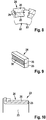
Weitere Vorteile und zweckmäßige Ausführungen sind den weiteren Ansprüchen, der Figurenbeschreibung und den Zeichnungen zu entnehmen. Es zeigen:
- Fig. 1
- eine Startvorrichtung für eine Brennkraftmaschine im Längsschnitt,
- Fig. 2
- der Kollektor der Kommutierungseinrichtung des elektrischen Startermotors der Startvorrichtung im Längsschnitt durch eine Lamelle, die radial innenliegend einen Aluminiumabschnitt und radial außenliegend einen Kupferabschnitt aufweist,
- Fig. 3 bis 5
- verschiedene Ausführungsvarianten von Lamellen mit innenliegendem Aluminiumabschnitt und außenliegendem Kupferabschnitt,
- Fig. 6
- einen Längsschnitt durch ein Kupferrohr und eine Aluminiumscheibe, welche stirnseitig an das Kupferrohr angeschweißt wird, wobei Kupferrohr und Aluminiumscheibe anschließend zu Lamellen vereinzelt werden,
- Fig. 7
- einen Längsschnitt durch einen Kollektor, dessen Lamellen gemäß
Fig. 6 aufgebaut sind, - Fig. 8
- einen Schnitt quer zur Kollektorlängsachse, mit einer Lamelle, deren Seitenwände Nuten für eine verbesserte Aufnahme in einer Kunststoffpressmasse des Kollektors aufweisen,
- Fig. 9
- in perspektivischer Einzeldarstellung eine Lamelle mit einer seitlichen Oberflächenstrukturierung für eine verbesserte Verbindung zur Kollektorpressmasse,
- Fig. 10
- einen Schnitt längs durch einen Kollektor mit einer Lamelle in einer weiteren Ausführung.
- Fig. 1
- a starting device for an internal combustion engine in longitudinal section,
- Fig. 2
- the collector of the commutation of the electric starter motor of the starting device in longitudinal section through a lamella having a radially inwardly an aluminum portion and radially outboard a copper section,
- Fig. 3 to 5
- various embodiments of lamellae with an internal aluminum section and an external copper section,
- Fig. 6
- a longitudinal section through a copper tube and an aluminum disc, which is welded frontally to the copper tube, copper tube and aluminum disc are then separated into slats,
- Fig. 7
- a longitudinal section through a collector, the fins according to
Fig. 6 are constructed - Fig. 8
- a section transverse to the collector longitudinal axis, with a lamella whose side walls have grooves for improved absorption in a plastic molding compound of the collector,
- Fig. 9
- a perspective view of a lamella with a lateral surface structuring for an improved connection to the collector molding compound,
- Fig. 10
- a section along a collector with a blade in another embodiment.
In den Figuren sind gleiche Bauteile mit gleichen Bezugszeichen versehen.In the figures, the same components are provided with the same reference numerals.
In
Die axiale Vorschubbewegung des Starterritzels 12 wird mithilfe eines elektromagnetischen Starterrelais 13 durchgeführt, das einen axial verstellbaren Hubanker 14 aufweist, welcher mit einem Gabelhebel gekoppelt ist. Bei einer axialen Stellbewegung des Hubankers 14 wird der am Gehäuse gelagerte Gabelhebel 15 verschwenkt, wodurch der Mitnehmer 8 einschließlich Starterritzel 12 in Achsrichtung verstellt wird.The axial feed movement of the
Der elektrische Startermotor 4 ist als Innenläufermotor ausgebildet und weist einen drehfest mit der Motorwelle 5 verbundenen Anker 16 auf, welcher elektrisch erregbare Ankerspulen enthält. Die Spulen im Anker 16 werden über eine Kommutierungseinrichtung 17 bestromt. Das von den elektrischen Ankerspulen erzeugte elektromagnetische Feld interagiert mit dem Magnetfeld von Permanentmagneten 18, die an der Innenseite des den Anker umgreifenden Stators angeordnet sind.The electric starter motor 4 is designed as an internal rotor motor and has a non-rotatably connected to the
Die Kommutierungseinrichtung 17 weist mehrere Feder-Bürste-Einheiten 19 auf, die jeweils gehäuseseitig eine Kohlebürste 20 und eine Bürstenfeder 21 umfassen, sowie einen ankerseitigen Kollektor 22. Die Kohlebürsten 20 werden von den Bürstenfedern 21 radial gegen die Mantelfläche des Kollektors 22 kraftbeaufschlagt. Kohlebürsten 20 und Bürstenfedern 21 sind zweckmäßigerweise in Bürstenhalterungen aufgenommen, die fest mit dem Gehäuse des Startermotors verbunden sind. Über den Umfang gleichmäßig verteilt sind insgesamt sechs Feder-Bürste-Einheiten 19 vorgesehen.The
In
Die Anschlussfahnen zur Ankerwicklung 27 bzw. die Enden der Ankerwicklung 27 liegen auf der Mantelfläche des Aluminiumabschnittes 25 auf, der axial länger ausgebildet ist als der Kupferabschnitt 26. Zwischen der Ankerwicklung 27 und der Stirnseite des axial verkürzt ausgeführten Kupferabschnittes 26 befindet sich ein Trennring 23a, der zweckmäßigerweise aus dem elektrisch isolierenden Material des Kollektorgrundkörpers 23 besteht. Der Trennring 23a stellt sicher, dass in die Trennstelle zwischen dem Aluminiumabschnitt 25 und dem Kupferabschnitt 26 keine Feuchtigkeit eindringen kann.The terminal lugs to the armature winding 27 and the ends of the armature winding 27 are on the lateral surface of the
Im Bereich beider axialer Stirnseiten übergreift die Kunststoffpressmasse des Kollektorgrundkörpers 23 die Lamelle 24 in Radialrichtung. Benachbart zur Ankerwicklung 27 erstreckt sich die Pressmasse des Kollektorgrundkörpers 23 in Radialrichtung bis etwa zur äußeren Mantelfläche des Aluminiumabschnittes 25. Auf der gegenüberliegenden axialen Stirnseite erstreckt sich der Kollektorgrundkörper 23 in Radialrichtung bis über die Trennstelle zwischen den Abschnitten 25 und 26 hinaus, jedoch mit geringfügigem radialem Abstand zur äußeren Mantelfläche des Kupferabschnittes 26.In the area of both axial end faces, the plastic molding compound of the
Der radiale Überstand, mit dem der Kollektorgrundkörper 23 radial über die Trennstelle zwischen dem Aluminiumabschnitt 25 und dem Messingabschnitt 26 übersteht, beträgt mindestens 1 % des Kollektor-Außendurchmessers, der durch die Außenseite des Kupferabschnittes 26 bestimmt ist. Zweckmäßigerweise ist der radiale Überstand über die Trennstelle hinaus maximal zwei Drittel der Radialdicke des Kupferabschnittes 26, so dass gewährleistet ist, dass zwar die Trennstelle von dem Kollektorgrundkörper übergriffen wird, jedoch zugleich ein ausreichender Abstand zur Außenseite des Kupferabschnittes 26 gegeben ist.The radial projection with which the collector
Im Ausführungsbeispiel gemäß
Im Ausführungsbeispiel gemäß
Im Ausführungsbeispiel gemäß
In
In
Im Ausführungsbeispiel gemäß
Im Ausführungsbeispiel gemäß
Im Ausführungsbeispiel gemäß
Claims (15)
- Commutation device for current transmission to an armature (16) of an electric machine, comprising an armature-side collector (22), which has a plurality of lamellas (24) in circumferential direction, wherein the lamellas (24) of the collector (22) each comprise an aluminum or a zinc section (25) and, on the outer side of the running surface, a copper or a brass section (26), with which brushes of the commutation device (17) are in contact, wherein the aluminum or zinc section (25) is connected to the copper or brass section (26), and wherein the aluminum or zinc section (25) is in electric contact with an armature winding (27),
characterized in that the aluminum or zinc section (25) is disposed at the axial end face of the copper or brass section (26). - Commutation device according to claim 1, characterized in that the aluminum or zinc section (25) forms an aluminum or zinc core located radially inside the running surface, which is a carrier of the copper or brass section (26) on the side located radially outwardly.
- Commutation device according to any one of claims 1 to 2, characterized in that the aluminum or zinc section (25) and the copper or brass section (26) are interconnected in a form-fit manner.
- Commutation device according to any one of claims 1 to 3, characterized in that the aluminum or zinc section (25) and the copper or brass section (26) are interconnected in a cohesive manner.
- Commutation device according to any one of claims 1 to 4, characterized in that the copper or brass section (26) is formed as a copper or brass layer which is applied to the aluminum or zinc section (25).
- Commutation device according to any one of claims 1 to 5, characterized in that at least a section of the lamella (24) is accommodated in an electrically insulating collector base body (23) of the collector (22).
- Commutation device according to claim 6, characterized in that the collector base body (23) radially overlaps the separation point between the aluminum or zinc section (25) and the copper or brass section (26).
- Commutation device according to claim 7, characterized in that the radial protrusion is at least 1% of the collector diameter (dK).
- Commutation device according to claim 7 or 8, characterized in that the radial protrusion is a maximum of two-third of the radial thickness of the copper or brass section (26).
- Commutation device according to any one of claims 6 to 9, characterized in that the collector base body (23) is formed as a plastics molding material.
- Commutation device according to any one of claims 1 to 10, characterized in that at least one side surface of at least one lamella (24) has a structured or non-flat surface.
- Commutation device according to any one of claims 1 to 11 for current transmission to an armature (16) of an electric machine provided as a starter motor (4) for an internal combustion engine.
- Electric machine, in particular starter motor (4) for a starter for an internal combustion engine, comprising a commutation device (17) according to any one of claims 1 to 12.
- Electric machine according to claim 13, which is provided as a starter motor (4) for a starter for an internal combustion engine.
- Starter for an internal combustion engine comprising an electric starter motor (4) according to claim 14.
Applications Claiming Priority (1)
| Application Number | Priority Date | Filing Date | Title |
|---|---|---|---|
| DE102012218708.1A DE102012218708A1 (en) | 2012-10-15 | 2012-10-15 | Commutation device for power transmission in an electrical machine |
Publications (3)
| Publication Number | Publication Date |
|---|---|
| EP2720353A2 EP2720353A2 (en) | 2014-04-16 |
| EP2720353A3 EP2720353A3 (en) | 2017-11-01 |
| EP2720353B1 true EP2720353B1 (en) | 2019-10-30 |
Family
ID=49118411
Family Applications (1)
| Application Number | Title | Priority Date | Filing Date |
|---|---|---|---|
| EP13183637.1A Active EP2720353B1 (en) | 2012-10-15 | 2013-09-10 | Commutation device for power transmission in an electric machine |
Country Status (4)
| Country | Link |
|---|---|
| EP (1) | EP2720353B1 (en) |
| CN (1) | CN103730802B (en) |
| DE (1) | DE102012218708A1 (en) |
| HU (1) | HUE046956T2 (en) |
Families Citing this family (1)
| Publication number | Priority date | Publication date | Assignee | Title |
|---|---|---|---|---|
| CN104103988B (en) * | 2014-07-10 | 2016-09-07 | 湖州展瑞机电科技有限公司 | A kind of light steering gear |
Family Cites Families (6)
| Publication number | Priority date | Publication date | Assignee | Title |
|---|---|---|---|---|
| FR1451412A (en) * | 1965-07-08 | 1966-01-07 | Advanced training in rotating electrical appliance collectors | |
| JPS63198557A (en) * | 1987-02-12 | 1988-08-17 | Mitsubishi Electric Corp | Dc motor |
| JP2001258213A (en) * | 2000-03-13 | 2001-09-21 | Hitachi Cable Ltd | Commutator segment |
| DE10041822A1 (en) | 2000-08-25 | 2002-03-07 | Bosch Gmbh Robert | Electrical starting device for internal combustion engines with overload protection |
| DE102010003048A1 (en) * | 2010-03-19 | 2011-09-22 | Robert Bosch Gmbh | Electric machine with balanced rotor |
| CN102684025A (en) * | 2011-03-09 | 2012-09-19 | 苏州工业园区安固电器有限公司 | Double-metal commutating sheet and processing process thereof |
-
2012
- 2012-10-15 DE DE102012218708.1A patent/DE102012218708A1/en not_active Withdrawn
-
2013
- 2013-09-10 HU HUE13183637A patent/HUE046956T2/en unknown
- 2013-09-10 EP EP13183637.1A patent/EP2720353B1/en active Active
- 2013-10-12 CN CN201310475677.6A patent/CN103730802B/en not_active Expired - Fee Related
Non-Patent Citations (1)
| Title |
|---|
| None * |
Also Published As
| Publication number | Publication date |
|---|---|
| EP2720353A2 (en) | 2014-04-16 |
| DE102012218708A1 (en) | 2014-04-17 |
| CN103730802A (en) | 2014-04-16 |
| HUE046956T2 (en) | 2020-04-28 |
| EP2720353A3 (en) | 2017-11-01 |
| CN103730802B (en) | 2017-03-01 |
Similar Documents
| Publication | Publication Date | Title |
|---|---|---|
| EP3300218B1 (en) | Contact ring, stator and electric motor | |
| EP3078099B1 (en) | Stator for an electronically commutated direct current motor | |
| EP3542445B1 (en) | Optimized electrical machine | |
| WO2011098447A2 (en) | Starting device | |
| DE102007032138A1 (en) | Disk-or rotor core stack fastening method for rotor of hybrid drive in motor vehicle, involves connecting disk or rotor core stack with shaft or carrier, and providing overlapping projections at inner and outer circumferential surfaces | |
| EP2720353B1 (en) | Commutation device for power transmission in an electric machine | |
| DE102008021071A1 (en) | Electric motor i.e. brush commutated electric motor, for use as actuating drive of motor vehicle, has brush commutator provided with brushes, which are movably arranged at brush offset angle to each other | |
| WO2005011084A1 (en) | Device, in particular electrical machine, comprising components mutually connected via an interference fit | |
| EP2814122B1 (en) | Method for producing a collector for a commutation device | |
| DE102014225379A1 (en) | Electric machine, in particular starter motor | |
| WO2009007428A1 (en) | Electric motor, in particular servomotor or drive motor in motor vehicles | |
| DE102008041685A1 (en) | Electric machine | |
| EP2073344A2 (en) | DC electric machine | |
| DE102006044491A1 (en) | Electrical machine, particularly electrical engines and generators has inner rotor and stator surrounding rotor, where stator is assembled from stator laminated core | |
| EP2800253B1 (en) | Method of manufacturing a commutation device's collector | |
| DE102016222924A1 (en) | Commutation device for an electrical machine | |
| WO2015067731A1 (en) | Commutation device in an electric machine | |
| DE102014216831A1 (en) | Electric machine with a disk pack | |
| WO2022214141A1 (en) | Electric machine | |
| DE102018009455A1 (en) | Electric motor for a starter of an internal combustion engine and starter, which is equipped with such an electric motor | |
| DE102014225514A1 (en) | Commutation device for an electrical machine | |
| DE102014225391A1 (en) | Commutation device for an electrical machine | |
| DE102014225385A1 (en) | Commutation device for an electrical machine | |
| DE102013103364A1 (en) | Method for producing a collector of an electrical machine | |
| DE102014225520A1 (en) | Commutation device for an electrical machine |
Legal Events
| Date | Code | Title | Description |
|---|---|---|---|
| PUAI | Public reference made under article 153(3) epc to a published international application that has entered the european phase |
Free format text: ORIGINAL CODE: 0009012 |
|
| AK | Designated contracting states |
Kind code of ref document: A2 Designated state(s): AL AT BE BG CH CY CZ DE DK EE ES FI FR GB GR HR HU IE IS IT LI LT LU LV MC MK MT NL NO PL PT RO RS SE SI SK SM TR |
|
| AX | Request for extension of the european patent |
Extension state: BA ME |
|
| PUAL | Search report despatched |
Free format text: ORIGINAL CODE: 0009013 |
|
| AK | Designated contracting states |
Kind code of ref document: A3 Designated state(s): AL AT BE BG CH CY CZ DE DK EE ES FI FR GB GR HR HU IE IS IT LI LT LU LV MC MK MT NL NO PL PT RO RS SE SI SK SM TR |
|
| AX | Request for extension of the european patent |
Extension state: BA ME |
|
| RIC1 | Information provided on ipc code assigned before grant |
Ipc: H02K 13/10 20060101AFI20170922BHEP |
|
| RAP1 | Party data changed (applicant data changed or rights of an application transferred) |
Owner name: SEG AUTOMOTIVE GERMANY GMBH |
|
| 17P | Request for examination filed |
Effective date: 20180430 |
|
| RBV | Designated contracting states (corrected) |
Designated state(s): AL AT BE BG CH CY CZ DE DK EE ES FI FR GB GR HR HU IE IS IT LI LT LU LV MC MK MT NL NO PL PT RO RS SE SI SK SM TR |
|
| GRAP | Despatch of communication of intention to grant a patent |
Free format text: ORIGINAL CODE: EPIDOSNIGR1 |
|
| STAA | Information on the status of an ep patent application or granted ep patent |
Free format text: STATUS: GRANT OF PATENT IS INTENDED |
|
| INTG | Intention to grant announced |
Effective date: 20190326 |
|
| GRAS | Grant fee paid |
Free format text: ORIGINAL CODE: EPIDOSNIGR3 |
|
| GRAA | (expected) grant |
Free format text: ORIGINAL CODE: 0009210 |
|
| STAA | Information on the status of an ep patent application or granted ep patent |
Free format text: STATUS: THE PATENT HAS BEEN GRANTED |
|
| AK | Designated contracting states |
Kind code of ref document: B1 Designated state(s): AL AT BE BG CH CY CZ DE DK EE ES FI FR GB GR HR HU IE IS IT LI LT LU LV MC MK MT NL NO PL PT RO RS SE SI SK SM TR |
|
| REG | Reference to a national code |
Ref country code: GB Ref legal event code: FG4D Free format text: NOT ENGLISH |
|
| REG | Reference to a national code |
Ref country code: CH Ref legal event code: EP |
|
| REG | Reference to a national code |
Ref country code: DE Ref legal event code: R096 Ref document number: 502013013821 Country of ref document: DE |
|
| REG | Reference to a national code |
Ref country code: AT Ref legal event code: REF Ref document number: 1197204 Country of ref document: AT Kind code of ref document: T Effective date: 20191115 |
|
| REG | Reference to a national code |
Ref country code: IE Ref legal event code: FG4D Free format text: LANGUAGE OF EP DOCUMENT: GERMAN |
|
| REG | Reference to a national code |
Ref country code: LT Ref legal event code: MG4D |
|
| REG | Reference to a national code |
Ref country code: HU Ref legal event code: AG4A Ref document number: E046956 Country of ref document: HU |
|
| PG25 | Lapsed in a contracting state [announced via postgrant information from national office to epo] |
Ref country code: GR Free format text: LAPSE BECAUSE OF FAILURE TO SUBMIT A TRANSLATION OF THE DESCRIPTION OR TO PAY THE FEE WITHIN THE PRESCRIBED TIME-LIMIT Effective date: 20200131 Ref country code: FI Free format text: LAPSE BECAUSE OF FAILURE TO SUBMIT A TRANSLATION OF THE DESCRIPTION OR TO PAY THE FEE WITHIN THE PRESCRIBED TIME-LIMIT Effective date: 20191030 Ref country code: BG Free format text: LAPSE BECAUSE OF FAILURE TO SUBMIT A TRANSLATION OF THE DESCRIPTION OR TO PAY THE FEE WITHIN THE PRESCRIBED TIME-LIMIT Effective date: 20200130 Ref country code: NO Free format text: LAPSE BECAUSE OF FAILURE TO SUBMIT A TRANSLATION OF THE DESCRIPTION OR TO PAY THE FEE WITHIN THE PRESCRIBED TIME-LIMIT Effective date: 20200130 Ref country code: PT Free format text: LAPSE BECAUSE OF FAILURE TO SUBMIT A TRANSLATION OF THE DESCRIPTION OR TO PAY THE FEE WITHIN THE PRESCRIBED TIME-LIMIT Effective date: 20200302 Ref country code: SE Free format text: LAPSE BECAUSE OF FAILURE TO SUBMIT A TRANSLATION OF THE DESCRIPTION OR TO PAY THE FEE WITHIN THE PRESCRIBED TIME-LIMIT Effective date: 20191030 Ref country code: LV Free format text: LAPSE BECAUSE OF FAILURE TO SUBMIT A TRANSLATION OF THE DESCRIPTION OR TO PAY THE FEE WITHIN THE PRESCRIBED TIME-LIMIT Effective date: 20191030 Ref country code: NL Free format text: LAPSE BECAUSE OF FAILURE TO SUBMIT A TRANSLATION OF THE DESCRIPTION OR TO PAY THE FEE WITHIN THE PRESCRIBED TIME-LIMIT Effective date: 20191030 Ref country code: PL Free format text: LAPSE BECAUSE OF FAILURE TO SUBMIT A TRANSLATION OF THE DESCRIPTION OR TO PAY THE FEE WITHIN THE PRESCRIBED TIME-LIMIT Effective date: 20191030 Ref country code: LT Free format text: LAPSE BECAUSE OF FAILURE TO SUBMIT A TRANSLATION OF THE DESCRIPTION OR TO PAY THE FEE WITHIN THE PRESCRIBED TIME-LIMIT Effective date: 20191030 Ref country code: ES Free format text: LAPSE BECAUSE OF FAILURE TO SUBMIT A TRANSLATION OF THE DESCRIPTION OR TO PAY THE FEE WITHIN THE PRESCRIBED TIME-LIMIT Effective date: 20191030 |
|
| REG | Reference to a national code |
Ref country code: NL Ref legal event code: MP Effective date: 20191030 |
|
| PG25 | Lapsed in a contracting state [announced via postgrant information from national office to epo] |
Ref country code: IS Free format text: LAPSE BECAUSE OF FAILURE TO SUBMIT A TRANSLATION OF THE DESCRIPTION OR TO PAY THE FEE WITHIN THE PRESCRIBED TIME-LIMIT Effective date: 20200229 Ref country code: HR Free format text: LAPSE BECAUSE OF FAILURE TO SUBMIT A TRANSLATION OF THE DESCRIPTION OR TO PAY THE FEE WITHIN THE PRESCRIBED TIME-LIMIT Effective date: 20191030 Ref country code: RS Free format text: LAPSE BECAUSE OF FAILURE TO SUBMIT A TRANSLATION OF THE DESCRIPTION OR TO PAY THE FEE WITHIN THE PRESCRIBED TIME-LIMIT Effective date: 20191030 |
|
| PG25 | Lapsed in a contracting state [announced via postgrant information from national office to epo] |
Ref country code: AL Free format text: LAPSE BECAUSE OF FAILURE TO SUBMIT A TRANSLATION OF THE DESCRIPTION OR TO PAY THE FEE WITHIN THE PRESCRIBED TIME-LIMIT Effective date: 20191030 |
|
| PG25 | Lapsed in a contracting state [announced via postgrant information from national office to epo] |
Ref country code: RO Free format text: LAPSE BECAUSE OF FAILURE TO SUBMIT A TRANSLATION OF THE DESCRIPTION OR TO PAY THE FEE WITHIN THE PRESCRIBED TIME-LIMIT Effective date: 20191030 Ref country code: CZ Free format text: LAPSE BECAUSE OF FAILURE TO SUBMIT A TRANSLATION OF THE DESCRIPTION OR TO PAY THE FEE WITHIN THE PRESCRIBED TIME-LIMIT Effective date: 20191030 Ref country code: EE Free format text: LAPSE BECAUSE OF FAILURE TO SUBMIT A TRANSLATION OF THE DESCRIPTION OR TO PAY THE FEE WITHIN THE PRESCRIBED TIME-LIMIT Effective date: 20191030 Ref country code: DK Free format text: LAPSE BECAUSE OF FAILURE TO SUBMIT A TRANSLATION OF THE DESCRIPTION OR TO PAY THE FEE WITHIN THE PRESCRIBED TIME-LIMIT Effective date: 20191030 |
|
| REG | Reference to a national code |
Ref country code: DE Ref legal event code: R097 Ref document number: 502013013821 Country of ref document: DE |
|
| PG25 | Lapsed in a contracting state [announced via postgrant information from national office to epo] |
Ref country code: SM Free format text: LAPSE BECAUSE OF FAILURE TO SUBMIT A TRANSLATION OF THE DESCRIPTION OR TO PAY THE FEE WITHIN THE PRESCRIBED TIME-LIMIT Effective date: 20191030 Ref country code: IT Free format text: LAPSE BECAUSE OF FAILURE TO SUBMIT A TRANSLATION OF THE DESCRIPTION OR TO PAY THE FEE WITHIN THE PRESCRIBED TIME-LIMIT Effective date: 20191030 Ref country code: SK Free format text: LAPSE BECAUSE OF FAILURE TO SUBMIT A TRANSLATION OF THE DESCRIPTION OR TO PAY THE FEE WITHIN THE PRESCRIBED TIME-LIMIT Effective date: 20191030 |
|
| PLBE | No opposition filed within time limit |
Free format text: ORIGINAL CODE: 0009261 |
|
| STAA | Information on the status of an ep patent application or granted ep patent |
Free format text: STATUS: NO OPPOSITION FILED WITHIN TIME LIMIT |
|
| 26N | No opposition filed |
Effective date: 20200731 |
|
| PG25 | Lapsed in a contracting state [announced via postgrant information from national office to epo] |
Ref country code: SI Free format text: LAPSE BECAUSE OF FAILURE TO SUBMIT A TRANSLATION OF THE DESCRIPTION OR TO PAY THE FEE WITHIN THE PRESCRIBED TIME-LIMIT Effective date: 20191030 |
|
| PG25 | Lapsed in a contracting state [announced via postgrant information from national office to epo] |
Ref country code: MC Free format text: LAPSE BECAUSE OF FAILURE TO SUBMIT A TRANSLATION OF THE DESCRIPTION OR TO PAY THE FEE WITHIN THE PRESCRIBED TIME-LIMIT Effective date: 20191030 |
|
| REG | Reference to a national code |
Ref country code: CH Ref legal event code: PL |
|
| GBPC | Gb: european patent ceased through non-payment of renewal fee |
Effective date: 20200910 |
|
| REG | Reference to a national code |
Ref country code: BE Ref legal event code: MM Effective date: 20200930 |
|
| PG25 | Lapsed in a contracting state [announced via postgrant information from national office to epo] |
Ref country code: LU Free format text: LAPSE BECAUSE OF NON-PAYMENT OF DUE FEES Effective date: 20200910 |
|
| PG25 | Lapsed in a contracting state [announced via postgrant information from national office to epo] |
Ref country code: BE Free format text: LAPSE BECAUSE OF NON-PAYMENT OF DUE FEES Effective date: 20200930 Ref country code: CH Free format text: LAPSE BECAUSE OF NON-PAYMENT OF DUE FEES Effective date: 20200930 Ref country code: LI Free format text: LAPSE BECAUSE OF NON-PAYMENT OF DUE FEES Effective date: 20200930 Ref country code: GB Free format text: LAPSE BECAUSE OF NON-PAYMENT OF DUE FEES Effective date: 20200910 Ref country code: IE Free format text: LAPSE BECAUSE OF NON-PAYMENT OF DUE FEES Effective date: 20200910 |
|
| PGFP | Annual fee paid to national office [announced via postgrant information from national office to epo] |
Ref country code: FR Payment date: 20210917 Year of fee payment: 9 |
|
| REG | Reference to a national code |
Ref country code: AT Ref legal event code: MM01 Ref document number: 1197204 Country of ref document: AT Kind code of ref document: T Effective date: 20200910 |
|
| REG | Reference to a national code |
Ref country code: DE Ref legal event code: R082 Ref document number: 502013013821 Country of ref document: DE Representative=s name: DEHNSGERMANY PARTNERSCHAFT VON PATENTANWAELTEN, DE Ref country code: DE Ref legal event code: R082 Ref document number: 502013013821 Country of ref document: DE Representative=s name: DEHNS GERMANY PARTNERSCHAFT MBB, DE |
|
| PG25 | Lapsed in a contracting state [announced via postgrant information from national office to epo] |
Ref country code: AT Free format text: LAPSE BECAUSE OF NON-PAYMENT OF DUE FEES Effective date: 20200910 |
|
| PG25 | Lapsed in a contracting state [announced via postgrant information from national office to epo] |
Ref country code: TR Free format text: LAPSE BECAUSE OF FAILURE TO SUBMIT A TRANSLATION OF THE DESCRIPTION OR TO PAY THE FEE WITHIN THE PRESCRIBED TIME-LIMIT Effective date: 20191030 Ref country code: MT Free format text: LAPSE BECAUSE OF FAILURE TO SUBMIT A TRANSLATION OF THE DESCRIPTION OR TO PAY THE FEE WITHIN THE PRESCRIBED TIME-LIMIT Effective date: 20191030 Ref country code: CY Free format text: LAPSE BECAUSE OF FAILURE TO SUBMIT A TRANSLATION OF THE DESCRIPTION OR TO PAY THE FEE WITHIN THE PRESCRIBED TIME-LIMIT Effective date: 20191030 |
|
| PG25 | Lapsed in a contracting state [announced via postgrant information from national office to epo] |
Ref country code: MK Free format text: LAPSE BECAUSE OF FAILURE TO SUBMIT A TRANSLATION OF THE DESCRIPTION OR TO PAY THE FEE WITHIN THE PRESCRIBED TIME-LIMIT Effective date: 20191030 |
|
| PGFP | Annual fee paid to national office [announced via postgrant information from national office to epo] |
Ref country code: DE Payment date: 20220623 Year of fee payment: 10 |
|
| PGFP | Annual fee paid to national office [announced via postgrant information from national office to epo] |
Ref country code: HU Payment date: 20220907 Year of fee payment: 10 |
|
| PG25 | Lapsed in a contracting state [announced via postgrant information from national office to epo] |
Ref country code: FR Free format text: LAPSE BECAUSE OF NON-PAYMENT OF DUE FEES Effective date: 20220930 |