EP2720211A1 - Other-vehicle detection device and other-vehicle detection method - Google Patents
Other-vehicle detection device and other-vehicle detection method Download PDFInfo
- Publication number
- EP2720211A1 EP2720211A1 EP11867236.9A EP11867236A EP2720211A1 EP 2720211 A1 EP2720211 A1 EP 2720211A1 EP 11867236 A EP11867236 A EP 11867236A EP 2720211 A1 EP2720211 A1 EP 2720211A1
- Authority
- EP
- European Patent Office
- Prior art keywords
- vehicle
- detection
- feature amount
- threshold value
- detected
- Prior art date
- Legal status (The legal status is an assumption and is not a legal conclusion. Google has not performed a legal analysis and makes no representation as to the accuracy of the status listed.)
- Granted
Links
Images



Classifications
-
- G—PHYSICS
- G08—SIGNALLING
- G08G—TRAFFIC CONTROL SYSTEMS
- G08G1/00—Traffic control systems for road vehicles
- G08G1/16—Anti-collision systems
-
- G—PHYSICS
- G06—COMPUTING OR CALCULATING; COUNTING
- G06V—IMAGE OR VIDEO RECOGNITION OR UNDERSTANDING
- G06V20/00—Scenes; Scene-specific elements
- G06V20/50—Context or environment of the image
- G06V20/56—Context or environment of the image exterior to a vehicle by using sensors mounted on the vehicle
- G06V20/58—Recognition of moving objects or obstacles, e.g. vehicles or pedestrians; Recognition of traffic objects, e.g. traffic signs, traffic lights or roads
-
- G—PHYSICS
- G06—COMPUTING OR CALCULATING; COUNTING
- G06V—IMAGE OR VIDEO RECOGNITION OR UNDERSTANDING
- G06V20/00—Scenes; Scene-specific elements
- G06V20/50—Context or environment of the image
- G06V20/56—Context or environment of the image exterior to a vehicle by using sensors mounted on the vehicle
- G06V20/58—Recognition of moving objects or obstacles, e.g. vehicles or pedestrians; Recognition of traffic objects, e.g. traffic signs, traffic lights or roads
- G06V20/584—Recognition of moving objects or obstacles, e.g. vehicles or pedestrians; Recognition of traffic objects, e.g. traffic signs, traffic lights or roads of vehicle lights or traffic lights
-
- G—PHYSICS
- G08—SIGNALLING
- G08G—TRAFFIC CONTROL SYSTEMS
- G08G1/00—Traffic control systems for road vehicles
- G08G1/16—Anti-collision systems
- G08G1/166—Anti-collision systems for active traffic, e.g. moving vehicles, pedestrians, bikes
-
- G—PHYSICS
- G08—SIGNALLING
- G08G—TRAFFIC CONTROL SYSTEMS
- G08G1/00—Traffic control systems for road vehicles
- G08G1/16—Anti-collision systems
- G08G1/167—Driving aids for lane monitoring, lane changing, e.g. blind spot detection
-
- B—PERFORMING OPERATIONS; TRANSPORTING
- B60—VEHICLES IN GENERAL
- B60R—VEHICLES, VEHICLE FITTINGS, OR VEHICLE PARTS, NOT OTHERWISE PROVIDED FOR
- B60R21/00—Arrangements or fittings on vehicles for protecting or preventing injuries to occupants or pedestrians in case of accidents or other traffic risks
- B60R21/01—Electrical circuits for triggering passive safety arrangements, e.g. airbags, safety belt tighteners, in case of vehicle accidents or impending vehicle accidents
- B60R21/013—Electrical circuits for triggering passive safety arrangements, e.g. airbags, safety belt tighteners, in case of vehicle accidents or impending vehicle accidents including means for detecting collisions, impending collisions or roll-over
-
- B—PERFORMING OPERATIONS; TRANSPORTING
- B60—VEHICLES IN GENERAL
- B60R—VEHICLES, VEHICLE FITTINGS, OR VEHICLE PARTS, NOT OTHERWISE PROVIDED FOR
- B60R21/00—Arrangements or fittings on vehicles for protecting or preventing injuries to occupants or pedestrians in case of accidents or other traffic risks
- B60R21/01—Electrical circuits for triggering passive safety arrangements, e.g. airbags, safety belt tighteners, in case of vehicle accidents or impending vehicle accidents
- B60R21/013—Electrical circuits for triggering passive safety arrangements, e.g. airbags, safety belt tighteners, in case of vehicle accidents or impending vehicle accidents including means for detecting collisions, impending collisions or roll-over
- B60R21/0132—Electrical circuits for triggering passive safety arrangements, e.g. airbags, safety belt tighteners, in case of vehicle accidents or impending vehicle accidents including means for detecting collisions, impending collisions or roll-over responsive to vehicle motion parameters, e.g. to vehicle longitudinal or transversal deceleration or speed value
-
- B—PERFORMING OPERATIONS; TRANSPORTING
- B60—VEHICLES IN GENERAL
- B60R—VEHICLES, VEHICLE FITTINGS, OR VEHICLE PARTS, NOT OTHERWISE PROVIDED FOR
- B60R21/00—Arrangements or fittings on vehicles for protecting or preventing injuries to occupants or pedestrians in case of accidents or other traffic risks
- B60R21/01—Electrical circuits for triggering passive safety arrangements, e.g. airbags, safety belt tighteners, in case of vehicle accidents or impending vehicle accidents
- B60R21/013—Electrical circuits for triggering passive safety arrangements, e.g. airbags, safety belt tighteners, in case of vehicle accidents or impending vehicle accidents including means for detecting collisions, impending collisions or roll-over
- B60R21/0134—Electrical circuits for triggering passive safety arrangements, e.g. airbags, safety belt tighteners, in case of vehicle accidents or impending vehicle accidents including means for detecting collisions, impending collisions or roll-over responsive to imminent contact with an obstacle, e.g. using radar systems
-
- G—PHYSICS
- G01—MEASURING; TESTING
- G01S—RADIO DIRECTION-FINDING; RADIO NAVIGATION; DETERMINING DISTANCE OR VELOCITY BY USE OF RADIO WAVES; LOCATING OR PRESENCE-DETECTING BY USE OF THE REFLECTION OR RERADIATION OF RADIO WAVES; ANALOGOUS ARRANGEMENTS USING OTHER WAVES
- G01S17/00—Systems using the reflection or reradiation of electromagnetic waves other than radio waves, e.g. lidar systems
- G01S17/88—Lidar systems specially adapted for specific applications
- G01S17/93—Lidar systems specially adapted for specific applications for anti-collision purposes
- G01S17/931—Lidar systems specially adapted for specific applications for anti-collision purposes of land vehicles
Definitions
- the present invention relates to an other-vehicle detection device and an other-vehicle detection method that detect an other-vehicle around a host vehicle using data acquired from the sensing device and the like.
- Patent Literature 1 Japanese Unexamined Patent Application Publication No. 2004-85337
- An object of the present invention is to provide an other-vehicle detection device and an other-vehicle detection method that can better detect the existence of the other-vehicle around the host vehicle according to the situation.
- the present invention provides an other-vehicle detection device which includes an other-vehicle detection unit that detects the other-vehicle around a host vehicle based on a predetermined feature amount.
- the other-vehicle detection unit changes a threshold value of the feature amount for detecting the other-vehicle, and detects the other-vehicle, based on a relative positional relationship between the other-vehicle and the host vehicle.
- the other-vehicle detection unit that detects the other-vehicle around the host vehicle based on the predetermined feature amount, changes the threshold value of the feature amount for detecting the other-vehicle, and detects the other-vehicle, based on the relative positional relationship between the other-vehicle and the host vehicle. In this way, it is possible to better detect the existence of the other-vehicle according to the situation.
- the other-vehicle detection unit can change the threshold value of the feature amount for detecting the other-vehicle such that the other-vehicle is detected with more difficulty, and can detect the other-vehicle.
- the other-vehicle detection unit changes the threshold value of the feature amount for detecting the other-vehicle such that the other-vehicle is detected with more difficulty, and detects the other-vehicle. Therefore, when the erroneous detection occurs, the traveling state of the host vehicle such as the avoidance operation needs to be changed, and it is possible to prevent the erroneous detection in the situation in which the erroneous detection cannot be easily accepted.
- the other-vehicle detection unit can detect the other-vehicle by the feature amount based on a detection value of sensors installed on the host vehicle, and change the threshold value of the feature amount for detecting the other-vehicle based on at least one of the position where the sensors are installed and the detection direction of the sensors, and can detect the other-vehicle.
- the other-vehicle detection unit detects the other-vehicle by the feature amount based on the detection value of the sensors installed on the host vehicle, and changes the threshold value of the feature amount for detecting the other-vehicle based on at least any of the position where the sensors are installed and the detection direction of the sensors, and detects the other-vehicle. Therefore, it is possible to detect the existence of the other-vehicle according to the position where sensors are installed or the detection direction of the sensors.
- the other-vehicle detection unit detects the other-vehicle by setting the threshold value of the feature amount for detecting the other-vehicle to the threshold value such that the other-vehicle is detected more easily, and after the traveling state of the host vehicle changes, the other-vehicle detection unit detects the other-vehicle by setting the threshold value of the feature amount for detecting the other-vehicle to the threshold value such that the other-vehicle is detected with more difficulty.
- the other-vehicle detection unit detects the other-vehicle by setting the threshold value of the feature amount for detecting the other-vehicle to the threshold value such that the other-vehicle is detected more easily, and after the traveling state of the host vehicle changes, detects the other-vehicle by setting the threshold value of the feature amount for detecting the other-vehicle to the threshold value such that the other-vehicle is detected with more difficulty.
- the present invention provides an other-vehicle detection method for detecting an other-vehicle around a host vehicle based on a predetermined feature amount.
- the other-vehicle detection method includes: changing a threshold value of the feature amount for detecting the other-vehicle, based on a relative positional relationship between the other-vehicle and the host vehicle, and detecting the other-vehicle.
- the feature amount based on a detection value of sensors installed on the host vehicle, and changes the threshold value of the feature amount for detecting the other-vehicle, based on at least any of the position where the sensors are installed and the detection direction of the sensors, and to detect the other-vehicle.
- the other-vehicle detection device and the other-vehicle detection method it is possible to better detect the existence of the other-vehicle according to the situation.
- an other-vehicle detection device 10a includes a surrounding information acquisition unit 12, a relative position detection unit 14, a detection reference value adjustment unit 16, and an other-vehicle detector 18.
- the other-vehicle detection device 10a according to the present embodiment is mounted on a vehicle.
- the other-vehicle detection device 10a detects an other-vehicle around a host vehicle, in order to perform an automatic driving that does not depend on a driver's operation or in order to guide a driver's driving operation.
- the surrounding information acquisition unit 12 acquires information, which is obtainable by sensors such as a camera, LIDAR or a radar, of an object existing around the host vehicle, and environmental information such as time and lane information, road information which is obtainable by a database searching, to properly output to a subsequent stage as it is necessary.
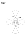
- sensors 120 of the surrounding information acquisition unit 12 are installed on four positions of the host vehicle VM: front part, left side surface, right side surface, and rear part.
- the relative position detection unit 14 detects a relative position between the object around the host vehicle and the host vehicle VM based on the information acquired by the surrounding information acquisition unit 12, to output to the subsequent stage.
- the detection reference value adjustment unit 16 changes the reference value which detects the other-vehicle from the detection value of the surrounding information acquired by the surrounding information acquisition unit 12, based on the relative position between the object around the host vehicle VM and the host vehicle VM detected by the relative position detection unit 14, to output the reference value.
- the other-vehicle detector 18 detects the other-vehicle based on the detection value of the surrounding information acquired by the surrounding information acquisition unit 12 and the reference value adjusted by the detection reference value adjustment unit 16.
- the other-vehicle detector 18 outputs other-vehicle information such as the position, speed and acceleration of the detected other-vehicle.
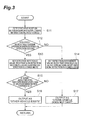
- the surrounding information acquisition unit 12 of the other-vehicle detection device 10a acquires information by the sensors such as a camera or a LIDAR, and the relative position detection unit 14 detects the relative position between the object around the host vehicle VM and the host vehicle VM (S11).
- the detection reference value adjustment unit 16 when an erroneous detection occurs, determines whether or not the relative positional relationship between the host vehicle VM and the detected object requires the host vehicle VM to change the traveling state by a sudden operation (S12).
- the sensors 120 are cameras, and the existence of the other-vehicle is determined by a degree of similarity of the acquired image and patterns used in pattern recognition.
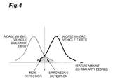
- a feature amount (degree of similarity) is plotted on the horizontal axis, and the distribution of the probability density in a case where the other-vehicle exists and in a case where the other-vehicle does not exists, is plotted.
- the distribution of the probability density in a case where the other-vehicle exists and in a case where the other-vehicle does not exists is separated, it is possible to determine the existence of the other-vehicle in the images obtained by the camera.
- the detection reference value adjustment unit 16 changes the detection reference value based on the presence or absence of the sudden operation accompanied by the erroneous detection.
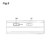
- the host vehicle VM travels straightforward.
- it is detected that the other-vehicle VO ahead does not exist while actually other-vehicle VO exists there is a possibility that the host vehicle VM may come into contact with the other-vehicle VO.
- the host vehicle VM tries to avoid the contact that might not occur originally by a sudden deceleration or a sudden steering.
- the detection reference value adjustment unit 16 shifts the detection reference value t in Fig. 3 to the right, to set the detection reference value such that the non-detection becomes more and the erroneous detection becomes less (S13).
- the host vehicle VM performs a lane change.
- the host vehicle VM comes in contact with the other-vehicle VO.
- the host vehicle VM does not perform the lane change at a time when the other-vehicle VO is erroneously detected in order to avoid contact.
- the non-detection may cause a contact.
- the detection reference value adjustment unit 16 shifts the detection reference value t in Fig. 3 to the left, to set the detection reference value such that the erroneous detection becomes more and the non-detection becomes less (S14).
- the detection reference value adjustment unit 16 may change the detection reference value per each sensor 120 based on the positions where the sensors 120 are installed and the detection direction. For example, regarding the sensor 120 disposed on the front part of the host vehicle VM, the detection reference value adjustment unit 16, for a similar reason described above, shifts the detection reference value t in Fig. 3 to the right, to set the detection reference value such that the non-detection becomes more and the erroneous detection becomes less. On the other hand, regarding the sensors 120 disposed on the sides of the host vehicle VM, the detection reference value adjustment unit 16, shifts the detection reference value t in Fig. 3 to the left, to set the detection reference value such that the erroneous detection becomes more and the non-detection becomes less.
- the other-vehicle detector 18 when the feature amount indicating the existence of other-vehicle VO is equal to or larger than the reference value, the other-vehicle detector 18 outputs that the other-vehicle exists (S15, S16), and when the feature amount representing the existence of other-vehicle VO is smaller than the reference value, the other-vehicle detector 18 outputs that the other-vehicle does not exist (S 15, S 17).
- the detection reference value adjustment unit 16 of the other-vehicle detection device 10a regarding the feature amount for detecting the other-vehicle VO around the host vehicle VM, based on the relative positional relationship between the other-vehicle VO and the host vehicle VM, changes the threshold value of the feature amount for detecting the other-vehicle VO, and detects the other-vehicle VO.
- the detection reference value adjustment unit 16 changes the threshold value of the feature amount for detecting the other-vehicle VM such that the other-vehicle VO is detected with more difficulty, and detects the other-vehicle VO.
- the traveling state of the host vehicle VM such as the avoidance operation needs to be changed, it is possible to prevent the erroneous detection in the situation where the erroneous detection cannot be easily accepted. That is, owing to the change of the detection reference value performed based on the presence or absence of the sudden operation of the host vehicle VM due to the erroneous detection, the safety is improved.
- the other-vehicle detector 18 detects the other-vehicle VO by the feature amount based on the detection value of the sensors 120 installed on the host vehicle VM, and changes the threshold value of the feature amount for detecting the other-vehicle VO based on at least one of the position where the sensors 120 are installed and the detection direction of the sensors 120 and detects the other-vehicle VO. Therefore, it is possible to detect the existence of the other-vehicle VO according to the position where sensors 120 are installed or the detection direction of the sensors 120.
- a host vehicle state detector 20 is included that detects whether or not the host vehicle VM causes the traveling state such as an acceleration, a deceleration, and a steering to be changed.
- the detection reference value adjustment unit 16 changes the detection reference value based on the traveling state of the host vehicle VM detected by the host vehicle state detector 20.
- the surrounding information acquisition unit 12 of the other-vehicle detection device 10b acquires information by the sensors such as a camera or a LIDAR, and the host vehicle state detector 20 detects the traveling state of the host vehicle VM (S21).
- the detection reference value adjustment unit 16 determines whether or not the traveling state of the host vehicle VM is in the state that acceleration, deceleration, or turning are started, and the state begins to be changed (S22). As illustrated in Fig. 9 , it is assumed that the host vehicle VM turns left at the intersection. Here, at the time after the host vehicle VM turns left, when the erroneous detection occurs, a new avoidance operation is needed which may disturb the traffic order, and there is a possibility to come in contact with another other-vehicle which actually exists. Therefore, after the travel state of the host vehicle begins to be changed, the detection reference value adjustment unit 16 shifts the detection reference value t in Fig. 3 to the right, and sets the detection reference value such that the non-detection becomes more and the erroneous detection becomes less (S23).
- the detection reference value adjustment unit 16 shifts the detection reference value t in Fig. 3 to the left, to set the detection reference value such that erroneous detection becomes more and the non-detection becomes less.
- the other-vehicle detector 18 when the feature amount representing the existence of other-vehicle VO is greater than or equal to the reference value, the other-vehicle detector 18 outputs that the other-vehicle exists (S25, S26), and when the feature amount representing the existence of other-vehicle VO is less than the reference value, the other-vehicle detector 18 outputs that the other-vehicle does not exist (S25, S27).
- the detection reference value adjustment unit 16 of the other-vehicle detection device 10b detects the other-vehicle VO by setting the threshold value of the feature amount for detecting the other-vehicle VO to the threshold value such that the other-vehicle VO is detected more easily, and after the traveling state of the host vehicle VM being changed, detects the other-vehicle VO by setting the threshold value of the feature amount for detecting the other-vehicle VO to the threshold value such that the other-vehicle VO is detected with more difficulty.
- the other-vehicle detection device and the other-vehicle detection method it is possible to detect the existence of the other-vehicle according to the situation more.
Landscapes
- Physics & Mathematics (AREA)
- General Physics & Mathematics (AREA)
- Engineering & Computer Science (AREA)
- Multimedia (AREA)
- Theoretical Computer Science (AREA)
- Traffic Control Systems (AREA)
Abstract
Description
- The present invention relates to an other-vehicle detection device and an other-vehicle detection method that detect an other-vehicle around a host vehicle using data acquired from the sensing device and the like.
- In recent years, a system in which a device that detects an object using data acquired from sensing devices such as a camera or a radar is mounted on a vehicle, and which causes a vehicle to automatically travel by the device, or supports a driver's driving operation is proposed. For example, in the device disclosed in
Patent Literature 1, in a coordination mode in a case where there is no contradiction in a detection result of the vehicle by a plurality of sensors, the sensor performs a measurement of the vehicle. In the device disclosed inPatent Literature 1, in a case where contradiction in a detection result occurs, the sensors are in a master-slave mode, the sensor which has detected the vehicle becomes a master sensor and confirms the accuracy and the sensor which has not detected the vehicle becomes a slave sensor and performs a new search. In the device inPatent Literature 1, in a case where other than any one of the sensors is inoperable, only the operable sensors perform the measurement of the vehicle, in an independent mode. - [Patent Literature 1] Japanese Unexamined Patent Application Publication No.
2004-85337 - However, in the technology described above, there is room for improvement in terms of appropriately detecting the existence of an other-vehicle around a host vehicle according to the situation.
- The present invention is made in view of such circumstances. An object of the present invention is to provide an other-vehicle detection device and an other-vehicle detection method that can better detect the existence of the other-vehicle around the host vehicle according to the situation.
- The present invention provides an other-vehicle detection device which includes an other-vehicle detection unit that detects the other-vehicle around a host vehicle based on a predetermined feature amount. The other-vehicle detection unit changes a threshold value of the feature amount for detecting the other-vehicle, and detects the other-vehicle, based on a relative positional relationship between the other-vehicle and the host vehicle.
- According to this configuration, the other-vehicle detection unit that detects the other-vehicle around the host vehicle based on the predetermined feature amount, changes the threshold value of the feature amount for detecting the other-vehicle, and detects the other-vehicle, based on the relative positional relationship between the other-vehicle and the host vehicle. In this way, it is possible to better detect the existence of the other-vehicle according to the situation.
- In this case, in a case where the relative positional relationship between the other-vehicle and the host vehicle needs to change the traveling state of the host vehicle when the other-vehicle is detected by the other-vehicle detection unit but actually does not exist, the other-vehicle detection unit can change the threshold value of the feature amount for detecting the other-vehicle such that the other-vehicle is detected with more difficulty, and can detect the other-vehicle.
- According to this configuration, in a case where the relative positional relationship between the other-vehicle and the host vehicle needs to change the traveling state of the host vehicle when the other-vehicle is detected by the other-vehicle detection unit but actually does not exist, the other-vehicle detection unit changes the threshold value of the feature amount for detecting the other-vehicle such that the other-vehicle is detected with more difficulty, and detects the other-vehicle. Therefore, when the erroneous detection occurs, the traveling state of the host vehicle such as the avoidance operation needs to be changed, and it is possible to prevent the erroneous detection in the situation in which the erroneous detection cannot be easily accepted.
- In addition, the other-vehicle detection unit can detect the other-vehicle by the feature amount based on a detection value of sensors installed on the host vehicle, and change the threshold value of the feature amount for detecting the other-vehicle based on at least one of the position where the sensors are installed and the detection direction of the sensors, and can detect the other-vehicle.
- According to this configuration, the other-vehicle detection unit detects the other-vehicle by the feature amount based on the detection value of the sensors installed on the host vehicle, and changes the threshold value of the feature amount for detecting the other-vehicle based on at least any of the position where the sensors are installed and the detection direction of the sensors, and detects the other-vehicle. Therefore, it is possible to detect the existence of the other-vehicle according to the position where sensors are installed or the detection direction of the sensors.
- In addition, it is preferable that, until the traveling state of the host vehicle changes, the other-vehicle detection unit detects the other-vehicle by setting the threshold value of the feature amount for detecting the other-vehicle to the threshold value such that the other-vehicle is detected more easily, and after the traveling state of the host vehicle changes, the other-vehicle detection unit detects the other-vehicle by setting the threshold value of the feature amount for detecting the other-vehicle to the threshold value such that the other-vehicle is detected with more difficulty.
- According to this configuration, the other-vehicle detection unit, until the traveling state of the host vehicle changes, detects the other-vehicle by setting the threshold value of the feature amount for detecting the other-vehicle to the threshold value such that the other-vehicle is detected more easily, and after the traveling state of the host vehicle changes, detects the other-vehicle by setting the threshold value of the feature amount for detecting the other-vehicle to the threshold value such that the other-vehicle is detected with more difficulty. Therefore, in the situation where the erroneous detection can be easily accepted before the traveling state of the host vehicle changes, it is possible to prevent the non-detection of the other-vehicle with the threshold value by which the other-vehicle is detected more easily. In the situation where the erroneous detection cannot be easily accepted after the traveling state of the host vehicle changes, it is possible to prevent the erroneous detection of the other-vehicle with the threshold value by which the other-vehicle is detected with more difficulty.
- In addition, the present invention provides an other-vehicle detection method for detecting an other-vehicle around a host vehicle based on a predetermined feature amount. The other-vehicle detection method includes: changing a threshold value of the feature amount for detecting the other-vehicle, based on a relative positional relationship between the other-vehicle and the host vehicle, and detecting the other-vehicle.
- In this case, in a case where the relative positional relationship between the other-vehicle and the host vehicle needs to change the traveling state of the host vehicle when the other-vehicle is detected but actually does not exist, it is possible to change the threshold value of the feature amount for detecting the other-vehicle such that the other-vehicle is detected with more difficulty, and to detect the other-vehicle.
- In addition, it is possible to detect the other-vehicle by the feature amount based on a detection value of sensors installed on the host vehicle, and changes the threshold value of the feature amount for detecting the other-vehicle, based on at least any of the position where the sensors are installed and the detection direction of the sensors, and to detect the other-vehicle.
- In addition, it is possible to detect the other-vehicle by setting the threshold value of the feature amount for detecting the other-vehicle to the threshold value such that the other-vehicle is detected more easily, until the traveling state of the host vehicle changes, and to detect the other-vehicle by setting the threshold value of the feature amount for detecting the other-vehicle to the threshold value such that the other-vehicle is detected with more difficulty, after the traveling state of the host vehicle changes.
- According to the other-vehicle detection device and the other-vehicle detection method, it is possible to better detect the existence of the other-vehicle according to the situation.
-
-
Fig. 1 is a diagram illustrating a configuration of an other-vehicle detection device according to a first embodiment. -
Fig. 2 is a plan view illustrating sensors installed on a host vehicle. -
Fig. 3 is a flow chart illustrating an operation of the other-vehicle detection device according to the first embodiment. -
Fig. 4 is a graph illustrating a probability density distribution in a case where a vehicle exists and in a case where a vehicle does not exist, in a specific feature amount space. -
Fig. 5 is a plan view illustrating a situation in a case where the host vehicle travels straightforward. -
Fig. 6 is a plan view illustrating a situation in a case where the host vehicle changes lanes. -
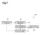
Fig. 7 is a diagram illustrating a configuration of the other-vehicle detection device according to the second embodiment. -
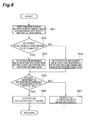
Fig. 8 is a flow chart illustrating an operation of the other-vehicle detection device according to the second embodiment. -
Fig. 9 is a plan view illustrating a situation in a case where the host vehicle turns left. - Hereinafter, an other-vehicle detection device and an other-vehicle detection method according to the embodiments of the present invention will be described with reference to the drawings.
- As illustrated in
Fig. 1 , an other-vehicle detection device 10a according to the first embodiment of the present invention includes a surroundinginformation acquisition unit 12, a relativeposition detection unit 14, a detection referencevalue adjustment unit 16, and an other-vehicle detector 18. The other-vehicle detection device 10a according to the present embodiment is mounted on a vehicle. The other-vehicle detection device 10a detects an other-vehicle around a host vehicle, in order to perform an automatic driving that does not depend on a driver's operation or in order to guide a driver's driving operation. - The surrounding
information acquisition unit 12 acquires information, which is obtainable by sensors such as a camera, LIDAR or a radar, of an object existing around the host vehicle, and environmental information such as time and lane information, road information which is obtainable by a database searching, to properly output to a subsequent stage as it is necessary. As illustrated inFig. 2 ,sensors 120 of the surroundinginformation acquisition unit 12 are installed on four positions of the host vehicle VM: front part, left side surface, right side surface, and rear part. - The relative
position detection unit 14 detects a relative position between the object around the host vehicle and the host vehicle VM based on the information acquired by the surroundinginformation acquisition unit 12, to output to the subsequent stage. - The detection reference
value adjustment unit 16 changes the reference value which detects the other-vehicle from the detection value of the surrounding information acquired by the surroundinginformation acquisition unit 12, based on the relative position between the object around the host vehicle VM and the host vehicle VM detected by the relativeposition detection unit 14, to output the reference value. - The other-
vehicle detector 18 detects the other-vehicle based on the detection value of the surrounding information acquired by the surroundinginformation acquisition unit 12 and the reference value adjusted by the detection referencevalue adjustment unit 16. The other-vehicle detector 18 outputs other-vehicle information such as the position, speed and acceleration of the detected other-vehicle. - Hereinafter, the operation of the other-
vehicle detection device 10a in the present embodiment will be described. As described inFig. 3 , the surroundinginformation acquisition unit 12 of the other-vehicle detection device 10a acquires information by the sensors such as a camera or a LIDAR, and the relativeposition detection unit 14 detects the relative position between the object around the host vehicle VM and the host vehicle VM (S11). - The detection reference
value adjustment unit 16, when an erroneous detection occurs, determines whether or not the relative positional relationship between the host vehicle VM and the detected object requires the host vehicle VM to change the traveling state by a sudden operation (S12). - Here, for example, it is assumed that the
sensors 120 are cameras, and the existence of the other-vehicle is determined by a degree of similarity of the acquired image and patterns used in pattern recognition. Here, as illustrated inFig. 4 , a feature amount (degree of similarity) is plotted on the horizontal axis, and the distribution of the probability density in a case where the other-vehicle exists and in a case where the other-vehicle does not exists, is plotted. As illustrated inFig. 4 , since the distribution of the probability density in a case where the other-vehicle exists and in a case where the other-vehicle does not exists is separated, it is possible to determine the existence of the other-vehicle in the images obtained by the camera. - In
Fig. 4 , when the reference value which detects the existence of the other-vehicle is set to be t, there is a region of non-detection in which it is detected that the other-vehicle does not exist while the other-vehicle actually exists, and a region of erroneous detection in which it is detected that the other-vehicle exists while the other-vehicle actually does not exist. When the detection reference value t is shifted to the left, the non-detection decreases while the erroneous detection increases. On the other hand, when the detection reference value t is shifted to the right, the erroneous detection decreases while the non-detection increases. Therefore, in the present embodiment, the detection referencevalue adjustment unit 16 changes the detection reference value based on the presence or absence of the sudden operation accompanied by the erroneous detection. - For example, as illustrated in
Fig. 5 , it is assumed that the host vehicle VM travels straightforward. In a case where it is detected that the other-vehicle VO ahead does not exist while actually other-vehicle VO exists (non-detection), there is a possibility that the host vehicle VM may come into contact with the other-vehicle VO. However, in a case where it is detected that the other-vehicle VO ahead exists while actually other-vehicle VO does not exist (erroneous detection), the host vehicle VM tries to avoid the contact that might not occur originally by a sudden deceleration or a sudden steering. As a result, the traffic order may be disturbed, and there is a concern that contact may occur with another other-vehicle which actually exists. In the case illustrated inFig. 5 , although both the non-detection and the erroneous detection are not preferred, erroneous detection is less preferred. Therefore, the detection referencevalue adjustment unit 16 shifts the detection reference value t inFig. 3 to the right, to set the detection reference value such that the non-detection becomes more and the erroneous detection becomes less (S13). - In contrast, as illustrated in
Fig. 6 , it is assumed that the host vehicle VM performs a lane change. In a case where the other-vehicle VO traveling in the neighboring lane is not detected, the host vehicle VM comes in contact with the other-vehicle VO. On the other hand, in a case where the other-vehicle VO is erroneously detected, the host vehicle VM does not perform the lane change at a time when the other-vehicle VO is erroneously detected in order to avoid contact. In the case illustrated inFig. 6 , there is a concern that the non-detection may cause a contact. However, it is expected that the erroneous detection may reduce the contact instead of imposing a constraint on the behavior of the host vehicle VM. As a result, in the case illustrated inFig. 6 , since the case of non-detection is less preferred, the detection referencevalue adjustment unit 16 shifts the detection reference value t inFig. 3 to the left, to set the detection reference value such that the erroneous detection becomes more and the non-detection becomes less (S14). - Here, for a similar reason, the detection reference
value adjustment unit 16 may change the detection reference value per eachsensor 120 based on the positions where thesensors 120 are installed and the detection direction. For example, regarding thesensor 120 disposed on the front part of the host vehicle VM, the detection referencevalue adjustment unit 16, for a similar reason described above, shifts the detection reference value t inFig. 3 to the right, to set the detection reference value such that the non-detection becomes more and the erroneous detection becomes less. On the other hand, regarding thesensors 120 disposed on the sides of the host vehicle VM, the detection referencevalue adjustment unit 16, shifts the detection reference value t inFig. 3 to the left, to set the detection reference value such that the erroneous detection becomes more and the non-detection becomes less. - In accordance with the reference value adjusted by the detection reference
value adjustment unit 16, when the feature amount indicating the existence of other-vehicle VO is equal to or larger than the reference value, the other-vehicle detector 18 outputs that the other-vehicle exists (S15, S16), and when the feature amount representing the existence of other-vehicle VO is smaller than the reference value, the other-vehicle detector 18 outputs that the other-vehicle does not exist (S 15, S 17). - According to the present embodiment, the detection reference
value adjustment unit 16 of the other-vehicle detection device 10a, regarding the feature amount for detecting the other-vehicle VO around the host vehicle VM, based on the relative positional relationship between the other-vehicle VO and the host vehicle VM, changes the threshold value of the feature amount for detecting the other-vehicle VO, and detects the other-vehicle VO. - In addition, according to the present embodiment, in a case where the relative positional relationship between the other-vehicle VO and the host vehicle VM needs to change the traveling state of the host vehicle VM when the other-vehicle VO is detected by the other-
vehicle detector 18 but actually does not exist, the detection referencevalue adjustment unit 16 changes the threshold value of the feature amount for detecting the other-vehicle VM such that the other-vehicle VO is detected with more difficulty, and detects the other-vehicle VO. For this reason, when the erroneous detection occurs, the traveling state of the host vehicle VM such as the avoidance operation needs to be changed, it is possible to prevent the erroneous detection in the situation where the erroneous detection cannot be easily accepted. That is, owing to the change of the detection reference value performed based on the presence or absence of the sudden operation of the host vehicle VM due to the erroneous detection, the safety is improved. - In addition, according to the present embodiment, the other-
vehicle detector 18 detects the other-vehicle VO by the feature amount based on the detection value of thesensors 120 installed on the host vehicle VM, and changes the threshold value of the feature amount for detecting the other-vehicle VO based on at least one of the position where thesensors 120 are installed and the detection direction of thesensors 120 and detects the other-vehicle VO. Therefore, it is possible to detect the existence of the other-vehicle VO according to the position wheresensors 120 are installed or the detection direction of thesensors 120. - Hereinafter, the second embodiment of the present invention will be described. As illustrated in
Fig. 7 , in the other-vehicle detection device 10a in the embodiment, a hostvehicle state detector 20 is included that detects whether or not the host vehicle VM causes the traveling state such as an acceleration, a deceleration, and a steering to be changed. The detection referencevalue adjustment unit 16 changes the detection reference value based on the traveling state of the host vehicle VM detected by the hostvehicle state detector 20. - Hereinafter, the operation of the other-
vehicle detection device 10b in the present embodiment will be described. As described inFig. 8 , the surroundinginformation acquisition unit 12 of the other-vehicle detection device 10b acquires information by the sensors such as a camera or a LIDAR, and the hostvehicle state detector 20 detects the traveling state of the host vehicle VM (S21). - The detection reference
value adjustment unit 16 determines whether or not the traveling state of the host vehicle VM is in the state that acceleration, deceleration, or turning are started, and the state begins to be changed (S22). As illustrated inFig. 9 , it is assumed that the host vehicle VM turns left at the intersection. Here, at the time after the host vehicle VM turns left, when the erroneous detection occurs, a new avoidance operation is needed which may disturb the traffic order, and there is a possibility to come in contact with another other-vehicle which actually exists. Therefore, after the travel state of the host vehicle begins to be changed, the detection referencevalue adjustment unit 16 shifts the detection reference value t inFig. 3 to the right, and sets the detection reference value such that the non-detection becomes more and the erroneous detection becomes less (S23). - On the other hand, at the time before the host vehicle VM turns left, when the non-detection occurs, there is a possibility of coming in contact with the other-vehicle VM or the like which actually exists, and in case of the erroneous detection, since the left turn is not performed. Therefore, before the traveling state of the host vehicle VM is changed, the detection reference
value adjustment unit 16 shifts the detection reference value t inFig. 3 to the left, to set the detection reference value such that erroneous detection becomes more and the non-detection becomes less. - Similar to the first embodiment described above, in accordance with the reference value adjusted by the detection reference
value adjustment unit 16, when the feature amount representing the existence of other-vehicle VO is greater than or equal to the reference value, the other-vehicle detector 18 outputs that the other-vehicle exists (S25, S26), and when the feature amount representing the existence of other-vehicle VO is less than the reference value, the other-vehicle detector 18 outputs that the other-vehicle does not exist (S25, S27). - According to the present embodiment, the detection reference
value adjustment unit 16 of the other-vehicle detection device 10b, until the traveling state of the host vehicle VM being changed, detects the other-vehicle VO by setting the threshold value of the feature amount for detecting the other-vehicle VO to the threshold value such that the other-vehicle VO is detected more easily, and after the traveling state of the host vehicle VM being changed, detects the other-vehicle VO by setting the threshold value of the feature amount for detecting the other-vehicle VO to the threshold value such that the other-vehicle VO is detected with more difficulty. Therefore, in the situation where the erroneous detection can be easily accepted before the traveling state of the host vehicle VM is changed, it is possible to prevent the non-detection of the other-vehicle VO with the threshold value by which the other-vehicle VO is detected more easily. In the situation where the erroneous detection cannot be easily accepted after the traveling state of the host vehicle VM is changed, it is possible to prevent the erroneous detection of the other-vehicle VO with the threshold value by which the other-vehicle VO is detected with more difficulty. - The present invention is not limited to the embodiments described above, and various modifications can be made without departing from the spirit or scope of the present invention.
- According to the other-vehicle detection device and the other-vehicle detection method, it is possible to detect the existence of the other-vehicle according to the situation more.
-
- 10a, 10b
- other-vehicle detection device
- 12
- surrounding information acquisition unit
- 14
- relative position detection unit
- 16
- detection reference value adjustment unit
- 18
- other-vehicle detector
- 20
- host vehicle state detector
- 120
- sensors
Claims (8)
- An other-vehicle detection device comprising:an other-vehicle detection unit that detects an other-vehicle around a host vehicle based on a predetermined feature amount,wherein, based on a relative positional relationship between the other-vehicle and the host vehicle, the other-vehicle detection unit changes a threshold value of the feature amount for detecting the other-vehicle, and detects the other-vehicle.
- The other-vehicle detection device according to Claim 1,
wherein, in a case where the relative positional relationship between the other-vehicle and the host vehicle needs to change a traveling state of the host vehicle when the other-vehicle is detected by the other vehicle detection unit but actually does not exist, the other-vehicle detection unit changes the threshold value of the feature amount for detecting the other-vehicle such that the other-vehicle is detected with more difficulty, and detects the other-vehicle. - The other-vehicle detection device according to Claim 1 or 2,
wherein the other-vehicle detection unit detects the other-vehicle by the feature amount based on a detection value of sensors installed on the host vehicle, and changes the threshold value of the feature amount for detecting the other-vehicle based on at least any of the position where the sensors are installed and the detection direction of the sensors, and detects the other-vehicle. - The other-vehicle detection device according to any one of Claims 1 to 3,
wherein, until the traveling state of the host vehicle changes, the other-vehicle detection unit detects the other-vehicle by setting the threshold value of the feature amount for detecting the other-vehicle to the threshold value such that the other-vehicle is detected more easily, and
wherein, after the traveling state of the host vehicle changes, the other-vehicle detection unit detects the other-vehicle by setting the threshold value of the feature amount for detecting the other-vehicle to the threshold value such that the other-vehicle is detected with more difficulty. - An other-vehicle detection method for detecting an other-vehicle around a host vehicle based on a predetermined feature amount, comprising:changing a threshold value of the feature amount for detecting the other-vehicle based on a relative positional relationship between the other-vehicle and the host vehicle, and detecting the other-vehicle.
- The other-vehicle detection method according to Claim 5, wherein, in a case where the relative positional relationship between the other-vehicle and the host vehicle needs to change the traveling state of the host vehicle when the other-vehicle is detected but actually does not exist, the threshold value of the feature amount for detecting the other-vehicle is changed such that the other-vehicle is detected with more difficulty, and the other-vehicle is detected.
- The other-vehicle detection method according to Claim 5 or 6, wherein the other-vehicle by the feature amount is detected based on a detection value of sensors installed on the host vehicle, and
wherein the threshold value of the feature amount for detecting the other-vehicle is changed, based on at least any of the position where the sensors are installed and the detection direction of the sensors, and the other-vehicle is detected. - The other-vehicle detection method according to any one of Claims 5 to 7, wherein, until the traveling state of the other-vehicle being changed, the other-vehicle is detected by setting the threshold value of the feature amount for detecting the other-vehicle to the threshold value such that the other-vehicle is detected more easily, and
wherein after the traveling state of the other-vehicle being changed, the other-vehicle is detected by setting the threshold value of the feature amount for detecting the other-vehicle to the threshold value such that the other-vehicle is detected with more difficulty.
Applications Claiming Priority (1)
| Application Number | Priority Date | Filing Date | Title |
|---|---|---|---|
| PCT/JP2011/063278 WO2012169052A1 (en) | 2011-06-09 | 2011-06-09 | Other-vehicle detection device and other-vehicle detection method |
Publications (3)
| Publication Number | Publication Date |
|---|---|
| EP2720211A1 true EP2720211A1 (en) | 2014-04-16 |
| EP2720211A4 EP2720211A4 (en) | 2015-02-25 |
| EP2720211B1 EP2720211B1 (en) | 2016-08-10 |
Family
ID=47295654
Family Applications (1)
| Application Number | Title | Priority Date | Filing Date |
|---|---|---|---|
| EP11867236.9A Active EP2720211B1 (en) | 2011-06-09 | 2011-06-09 | Other-vehicle detection device and other-vehicle detection method |
Country Status (4)
| Country | Link |
|---|---|
| US (1) | US9495873B2 (en) |
| EP (1) | EP2720211B1 (en) |
| JP (1) | JP5737396B2 (en) |
| WO (1) | WO2012169052A1 (en) |
Families Citing this family (4)
| Publication number | Priority date | Publication date | Assignee | Title |
|---|---|---|---|---|
| JP6558393B2 (en) | 2017-04-06 | 2019-08-14 | トヨタ自動車株式会社 | Course setting device and course setting method |
| KR102371616B1 (en) * | 2017-11-07 | 2022-03-07 | 현대자동차주식회사 | Apparatus and method for associating sensor data of vehicle |
| JP7786826B2 (en) * | 2022-12-13 | 2025-12-16 | キヤノン株式会社 | Information processing device, mobile object, information processing method, and computer program |
| US12552369B2 (en) | 2022-10-11 | 2026-02-17 | Canon Kabushiki Kaisha | Information processing apparatus, movable apparatus, information processing method, and storage medium |
Family Cites Families (50)
| Publication number | Priority date | Publication date | Assignee | Title |
|---|---|---|---|---|
| JP3470453B2 (en) | 1995-04-06 | 2003-11-25 | 株式会社デンソー | Inter-vehicle distance control device |
| US6025797A (en) | 1997-07-22 | 2000-02-15 | Denso Corporation | Angular shift determining apparatus for determining angular shift of central axis of radar used in automotive obstacle detection system |
| JP2001242242A (en) | 2000-02-29 | 2001-09-07 | Hitachi Ltd | Millimeter wave radar device with detection performance improvement function |
| DE10036276A1 (en) | 2000-07-26 | 2002-02-07 | Daimler Chrysler Ag | Automatic braking and steering system for a vehicle |
| US6456231B1 (en) | 2001-06-01 | 2002-09-24 | Mcewan Technologies, Llc | Radar sensor having a CFAR detector |
| US6615137B2 (en) * | 2001-06-26 | 2003-09-02 | Medius, Inc. | Method and apparatus for transferring information between vehicles |
| JP3896852B2 (en) | 2002-01-16 | 2007-03-22 | 株式会社デンソー | Vehicle collision damage reduction device |
| JP3891011B2 (en) | 2002-03-12 | 2007-03-07 | 株式会社デンソー | Cruise control device, program |
| AU2003225228A1 (en) | 2002-05-03 | 2003-11-17 | Donnelly Corporation | Object detection system for vehicle |
| JP2004085337A (en) | 2002-08-27 | 2004-03-18 | Fujitsu Ltd | Vehicle detection method and vehicle detection device |
| DE10244205A1 (en) | 2002-09-23 | 2004-03-25 | Robert Bosch Gmbh | Vehicle collision prevention method for preventing collision between motor vehicles uses sensors to detect a vehicle's surroundings and its amount of movement |
| JP3985748B2 (en) * | 2003-07-08 | 2007-10-03 | 日産自動車株式会社 | In-vehicle obstacle detection device |
| JP4449409B2 (en) | 2003-10-27 | 2010-04-14 | 日産自動車株式会社 | Vehicle occupant protection device |
| JP4021401B2 (en) * | 2003-11-07 | 2007-12-12 | 本田技研工業株式会社 | Vehicle object detection device |
| DE10360890A1 (en) | 2003-12-19 | 2005-07-21 | Robert Bosch Gmbh | Radar sensor and method for its operation |
| DE102004019651A1 (en) * | 2004-04-22 | 2005-11-17 | Siemens Ag | Blind spot sensor system |
| US7409295B2 (en) | 2004-08-09 | 2008-08-05 | M/A-Com, Inc. | Imminent-collision detection system and process |
| JP2006072830A (en) * | 2004-09-03 | 2006-03-16 | Aisin Aw Co Ltd | Operation supporting system and operation supporting module |
| US7683827B2 (en) | 2004-12-15 | 2010-03-23 | Valeo Radar Systems, Inc. | System and method for reducing the effect of a radar interference signal |
| EP1851565B1 (en) | 2005-01-18 | 2009-10-14 | Marinvent Corporation | Method and apparatus for performing a sensor fusion to provide a position of a target-of-interest |
| US7940206B2 (en) | 2005-04-20 | 2011-05-10 | Accipiter Radar Technologies Inc. | Low-cost, high-performance radar networks |
| JP2006309445A (en) | 2005-04-27 | 2006-11-09 | Aisin Aw Co Ltd | Driving-support device |
| JP4654803B2 (en) * | 2005-07-07 | 2011-03-23 | 日産自動車株式会社 | Radar device for vehicle periphery monitoring |
| DE602005017144D1 (en) | 2005-08-18 | 2009-11-26 | Honda Res Inst Europe Gmbh | Driver assistance system |
| JP4772425B2 (en) * | 2005-08-25 | 2011-09-14 | 本田技研工業株式会社 | Object detection device |
| DE102006006850B4 (en) | 2006-02-15 | 2022-12-29 | Bayerische Motoren Werke Aktiengesellschaft | Method of aligning a pivotable vehicle sensor |
| WO2007102367A1 (en) | 2006-02-28 | 2007-09-13 | Toyota Jidosha Kabushiki Kaisha | Object course prediction method, device, program, and automatic driving system |
| US20070233353A1 (en) | 2006-03-28 | 2007-10-04 | Alexander Kade | Enhanced adaptive cruise control system with forward vehicle collision mitigation |
| JP4830594B2 (en) | 2006-04-05 | 2011-12-07 | トヨタ自動車株式会社 | Object detection device |
| JP2007329762A (en) | 2006-06-08 | 2007-12-20 | Fujitsu Ten Ltd | Object candidate area detection apparatus, object candidate area detection method, pedestrian recognition apparatus, and vehicle control apparatus |
| JP4434179B2 (en) | 2006-06-28 | 2010-03-17 | 日産自動車株式会社 | VEHICLE DRIVE OPERATION ASSISTANCE DEVICE AND VEHICLE HAVING VEHICLE DRIVE OPERATION ASSISTANCE DEVICE |
| JP4946228B2 (en) | 2006-07-18 | 2012-06-06 | トヨタ自動車株式会社 | In-vehicle pedestrian detection device |
| JP4984713B2 (en) | 2006-07-25 | 2012-07-25 | 株式会社デンソー | Radar equipment |
| JP4872517B2 (en) | 2006-08-07 | 2012-02-08 | トヨタ自動車株式会社 | Obstacle recognition device |
| JP4876772B2 (en) * | 2006-08-15 | 2012-02-15 | トヨタ自動車株式会社 | Interrupting vehicle determination device |
| JP4762830B2 (en) | 2006-08-23 | 2011-08-31 | アルパイン株式会社 | Perimeter monitoring system |
| WO2008043852A1 (en) | 2006-10-13 | 2008-04-17 | Continental Teves Ag & Co. Ohg | System for determining objects |
| JP4420011B2 (en) | 2006-11-16 | 2010-02-24 | 株式会社日立製作所 | Object detection device |
| JP2008126755A (en) | 2006-11-17 | 2008-06-05 | Toyota Motor Corp | Driving support device |
| JP4945222B2 (en) | 2006-11-28 | 2012-06-06 | 日立オートモティブシステムズ株式会社 | Sudden event elimination judgment system |
| JP2008152391A (en) * | 2006-12-14 | 2008-07-03 | Toyota Motor Corp | Vehicle periphery monitoring device |
| EP3624086B1 (en) | 2007-01-25 | 2025-07-09 | Magna Electronics Inc. | Radar sensing system for vehicle |
| JP4412337B2 (en) * | 2007-03-08 | 2010-02-10 | トヨタ自動車株式会社 | Ambient environment estimation device and ambient environment estimation system |
| JP4623057B2 (en) | 2007-06-05 | 2011-02-02 | トヨタ自動車株式会社 | Moving area acquisition device for own vehicle |
| JP4985232B2 (en) | 2007-08-27 | 2012-07-25 | トヨタ自動車株式会社 | Collision determination device |
| US7639171B2 (en) | 2007-09-27 | 2009-12-29 | Delphi Technologies, Inc. | Radar system and method of digital beamforming |
| JP2009122859A (en) | 2007-11-13 | 2009-06-04 | Toyota Motor Corp | Object detection device |
| JP5300357B2 (en) | 2008-07-22 | 2013-09-25 | 日立オートモティブシステムズ株式会社 | Collision prevention support device |
| JP4877364B2 (en) | 2009-07-10 | 2012-02-15 | トヨタ自動車株式会社 | Object detection device |
| JP2011048641A (en) * | 2009-08-27 | 2011-03-10 | Toyota Motor Corp | Object detection device and driving support device |
-
2011
- 2011-06-09 EP EP11867236.9A patent/EP2720211B1/en active Active
- 2011-06-09 US US14/124,171 patent/US9495873B2/en active Active
- 2011-06-09 WO PCT/JP2011/063278 patent/WO2012169052A1/en not_active Ceased
- 2011-06-09 JP JP2013519317A patent/JP5737396B2/en active Active
Also Published As
| Publication number | Publication date |
|---|---|
| EP2720211A4 (en) | 2015-02-25 |
| JPWO2012169052A1 (en) | 2015-02-23 |
| US20140104078A1 (en) | 2014-04-17 |
| WO2012169052A1 (en) | 2012-12-13 |
| EP2720211B1 (en) | 2016-08-10 |
| JP5737396B2 (en) | 2015-06-17 |
| US9495873B2 (en) | 2016-11-15 |
Similar Documents
| Publication | Publication Date | Title |
|---|---|---|
| US8447484B2 (en) | Branch-lane entry judging system | |
| JP4558758B2 (en) | Obstacle recognition device for vehicles | |
| EP2549456B1 (en) | Driving assistance device | |
| EP3086990B1 (en) | Method and system for driver assistance for a vehicle | |
| CN109204311B (en) | A vehicle speed control method and device | |
| US20170253177A1 (en) | Vehicle lighting system | |
| JP5953810B2 (en) | Vehicle travel support device | |
| US20170341642A1 (en) | Vehicle control apparatus | |
| WO2016117467A1 (en) | Travel control device and travel control method for vehicle | |
| US9102329B2 (en) | Tracking control apparatus | |
| JP6654923B2 (en) | Map information output device | |
| EP2784762A1 (en) | Vehicle identification device | |
| JP5202741B2 (en) | Branch entry judgment device | |
| WO2016117468A1 (en) | Travel control device and travel control method for vehicle | |
| WO2018074288A1 (en) | Vehicle recognition device and vehicle recognition method | |
| JP6456682B2 (en) | Traveling line recognition device | |
| US10482332B2 (en) | Pedestrian determining apparatus for determining whether an object is a pedestrian crossing ahead of an own vehicle | |
| US10996317B2 (en) | Object detection apparatus and object detection method | |
| JP2011048641A (en) | Object detection device and driving support device | |
| JP6544168B2 (en) | Vehicle control device and vehicle control method | |
| JP6717240B2 (en) | Target detection device | |
| US20210001883A1 (en) | Action selection device, computer readable medium, and action selection method | |
| JP2018036796A (en) | External information processing equipment | |
| US9495873B2 (en) | Other-vehicle detection device and other-vehicle detection method | |
| JP6231540B2 (en) | Driving assistance device |
Legal Events
| Date | Code | Title | Description |
|---|---|---|---|
| PUAI | Public reference made under article 153(3) epc to a published international application that has entered the european phase |
Free format text: ORIGINAL CODE: 0009012 |
|
| 17P | Request for examination filed |
Effective date: 20131211 |
|
| AK | Designated contracting states |
Kind code of ref document: A1 Designated state(s): AL AT BE BG CH CY CZ DE DK EE ES FI FR GB GR HR HU IE IS IT LI LT LU LV MC MK MT NL NO PL PT RO RS SE SI SK SM TR |
|
| DAX | Request for extension of the european patent (deleted) | ||
| A4 | Supplementary search report drawn up and despatched |
Effective date: 20150123 |
|
| RIC1 | Information provided on ipc code assigned before grant |
Ipc: G06K 9/00 20060101ALI20150119BHEP Ipc: G08G 1/16 20060101AFI20150119BHEP |
|
| GRAP | Despatch of communication of intention to grant a patent |
Free format text: ORIGINAL CODE: EPIDOSNIGR1 |
|
| INTG | Intention to grant announced |
Effective date: 20160329 |
|
| GRAS | Grant fee paid |
Free format text: ORIGINAL CODE: EPIDOSNIGR3 |
|
| GRAA | (expected) grant |
Free format text: ORIGINAL CODE: 0009210 |
|
| AK | Designated contracting states |
Kind code of ref document: B1 Designated state(s): AL AT BE BG CH CY CZ DE DK EE ES FI FR GB GR HR HU IE IS IT LI LT LU LV MC MK MT NL NO PL PT RO RS SE SI SK SM TR |
|
| REG | Reference to a national code |
Ref country code: GB Ref legal event code: FG4D |
|
| REG | Reference to a national code |
Ref country code: CH Ref legal event code: EP Ref country code: AT Ref legal event code: REF Ref document number: 819658 Country of ref document: AT Kind code of ref document: T Effective date: 20160815 |
|
| REG | Reference to a national code |
Ref country code: IE Ref legal event code: FG4D |
|
| REG | Reference to a national code |
Ref country code: DE Ref legal event code: R096 Ref document number: 602011029183 Country of ref document: DE |
|
| REG | Reference to a national code |
Ref country code: LT Ref legal event code: MG4D |
|
| REG | Reference to a national code |
Ref country code: NL Ref legal event code: MP Effective date: 20160810 |
|
| REG | Reference to a national code |
Ref country code: AT Ref legal event code: MK05 Ref document number: 819658 Country of ref document: AT Kind code of ref document: T Effective date: 20160810 |
|
| PG25 | Lapsed in a contracting state [announced via postgrant information from national office to epo] |
Ref country code: NL Free format text: LAPSE BECAUSE OF FAILURE TO SUBMIT A TRANSLATION OF THE DESCRIPTION OR TO PAY THE FEE WITHIN THE PRESCRIBED TIME-LIMIT Effective date: 20160810 Ref country code: IS Free format text: LAPSE BECAUSE OF FAILURE TO SUBMIT A TRANSLATION OF THE DESCRIPTION OR TO PAY THE FEE WITHIN THE PRESCRIBED TIME-LIMIT Effective date: 20161210 Ref country code: RS Free format text: LAPSE BECAUSE OF FAILURE TO SUBMIT A TRANSLATION OF THE DESCRIPTION OR TO PAY THE FEE WITHIN THE PRESCRIBED TIME-LIMIT Effective date: 20160810 Ref country code: FI Free format text: LAPSE BECAUSE OF FAILURE TO SUBMIT A TRANSLATION OF THE DESCRIPTION OR TO PAY THE FEE WITHIN THE PRESCRIBED TIME-LIMIT Effective date: 20160810 Ref country code: IT Free format text: LAPSE BECAUSE OF FAILURE TO SUBMIT A TRANSLATION OF THE DESCRIPTION OR TO PAY THE FEE WITHIN THE PRESCRIBED TIME-LIMIT Effective date: 20160810 Ref country code: NO Free format text: LAPSE BECAUSE OF FAILURE TO SUBMIT A TRANSLATION OF THE DESCRIPTION OR TO PAY THE FEE WITHIN THE PRESCRIBED TIME-LIMIT Effective date: 20161110 Ref country code: HR Free format text: LAPSE BECAUSE OF FAILURE TO SUBMIT A TRANSLATION OF THE DESCRIPTION OR TO PAY THE FEE WITHIN THE PRESCRIBED TIME-LIMIT Effective date: 20160810 Ref country code: LT Free format text: LAPSE BECAUSE OF FAILURE TO SUBMIT A TRANSLATION OF THE DESCRIPTION OR TO PAY THE FEE WITHIN THE PRESCRIBED TIME-LIMIT Effective date: 20160810 |
|
| PG25 | Lapsed in a contracting state [announced via postgrant information from national office to epo] |
Ref country code: ES Free format text: LAPSE BECAUSE OF FAILURE TO SUBMIT A TRANSLATION OF THE DESCRIPTION OR TO PAY THE FEE WITHIN THE PRESCRIBED TIME-LIMIT Effective date: 20160810 Ref country code: PT Free format text: LAPSE BECAUSE OF FAILURE TO SUBMIT A TRANSLATION OF THE DESCRIPTION OR TO PAY THE FEE WITHIN THE PRESCRIBED TIME-LIMIT Effective date: 20161212 Ref country code: SE Free format text: LAPSE BECAUSE OF FAILURE TO SUBMIT A TRANSLATION OF THE DESCRIPTION OR TO PAY THE FEE WITHIN THE PRESCRIBED TIME-LIMIT Effective date: 20160810 Ref country code: AT Free format text: LAPSE BECAUSE OF FAILURE TO SUBMIT A TRANSLATION OF THE DESCRIPTION OR TO PAY THE FEE WITHIN THE PRESCRIBED TIME-LIMIT Effective date: 20160810 Ref country code: LV Free format text: LAPSE BECAUSE OF FAILURE TO SUBMIT A TRANSLATION OF THE DESCRIPTION OR TO PAY THE FEE WITHIN THE PRESCRIBED TIME-LIMIT Effective date: 20160810 Ref country code: PL Free format text: LAPSE BECAUSE OF FAILURE TO SUBMIT A TRANSLATION OF THE DESCRIPTION OR TO PAY THE FEE WITHIN THE PRESCRIBED TIME-LIMIT Effective date: 20160810 Ref country code: GR Free format text: LAPSE BECAUSE OF FAILURE TO SUBMIT A TRANSLATION OF THE DESCRIPTION OR TO PAY THE FEE WITHIN THE PRESCRIBED TIME-LIMIT Effective date: 20161111 |
|
| REG | Reference to a national code |
Ref country code: DE Ref legal event code: R084 Ref document number: 602011029183 Country of ref document: DE |
|
| PG25 | Lapsed in a contracting state [announced via postgrant information from national office to epo] |
Ref country code: RO Free format text: LAPSE BECAUSE OF FAILURE TO SUBMIT A TRANSLATION OF THE DESCRIPTION OR TO PAY THE FEE WITHIN THE PRESCRIBED TIME-LIMIT Effective date: 20160810 Ref country code: EE Free format text: LAPSE BECAUSE OF FAILURE TO SUBMIT A TRANSLATION OF THE DESCRIPTION OR TO PAY THE FEE WITHIN THE PRESCRIBED TIME-LIMIT Effective date: 20160810 |
|
| REG | Reference to a national code |
Ref country code: DE Ref legal event code: R097 Ref document number: 602011029183 Country of ref document: DE |
|
| PG25 | Lapsed in a contracting state [announced via postgrant information from national office to epo] |
Ref country code: BG Free format text: LAPSE BECAUSE OF FAILURE TO SUBMIT A TRANSLATION OF THE DESCRIPTION OR TO PAY THE FEE WITHIN THE PRESCRIBED TIME-LIMIT Effective date: 20161110 Ref country code: BE Free format text: LAPSE BECAUSE OF FAILURE TO SUBMIT A TRANSLATION OF THE DESCRIPTION OR TO PAY THE FEE WITHIN THE PRESCRIBED TIME-LIMIT Effective date: 20160810 Ref country code: SM Free format text: LAPSE BECAUSE OF FAILURE TO SUBMIT A TRANSLATION OF THE DESCRIPTION OR TO PAY THE FEE WITHIN THE PRESCRIBED TIME-LIMIT Effective date: 20160810 Ref country code: CZ Free format text: LAPSE BECAUSE OF FAILURE TO SUBMIT A TRANSLATION OF THE DESCRIPTION OR TO PAY THE FEE WITHIN THE PRESCRIBED TIME-LIMIT Effective date: 20160810 Ref country code: DK Free format text: LAPSE BECAUSE OF FAILURE TO SUBMIT A TRANSLATION OF THE DESCRIPTION OR TO PAY THE FEE WITHIN THE PRESCRIBED TIME-LIMIT Effective date: 20160810 Ref country code: SK Free format text: LAPSE BECAUSE OF FAILURE TO SUBMIT A TRANSLATION OF THE DESCRIPTION OR TO PAY THE FEE WITHIN THE PRESCRIBED TIME-LIMIT Effective date: 20160810 |
|
| PLBE | No opposition filed within time limit |
Free format text: ORIGINAL CODE: 0009261 |
|
| STAA | Information on the status of an ep patent application or granted ep patent |
Free format text: STATUS: NO OPPOSITION FILED WITHIN TIME LIMIT |
|
| 26N | No opposition filed |
Effective date: 20170511 |
|
| PG25 | Lapsed in a contracting state [announced via postgrant information from national office to epo] |
Ref country code: SI Free format text: LAPSE BECAUSE OF FAILURE TO SUBMIT A TRANSLATION OF THE DESCRIPTION OR TO PAY THE FEE WITHIN THE PRESCRIBED TIME-LIMIT Effective date: 20160810 |
|
| PG25 | Lapsed in a contracting state [announced via postgrant information from national office to epo] |
Ref country code: MC Free format text: LAPSE BECAUSE OF FAILURE TO SUBMIT A TRANSLATION OF THE DESCRIPTION OR TO PAY THE FEE WITHIN THE PRESCRIBED TIME-LIMIT Effective date: 20160810 |
|
| REG | Reference to a national code |
Ref country code: CH Ref legal event code: PL |
|
| GBPC | Gb: european patent ceased through non-payment of renewal fee |
Effective date: 20170609 |
|
| REG | Reference to a national code |
Ref country code: IE Ref legal event code: MM4A |
|
| REG | Reference to a national code |
Ref country code: FR Ref legal event code: ST Effective date: 20180228 |
|
| PG25 | Lapsed in a contracting state [announced via postgrant information from national office to epo] |
Ref country code: LU Free format text: LAPSE BECAUSE OF NON-PAYMENT OF DUE FEES Effective date: 20170609 Ref country code: GB Free format text: LAPSE BECAUSE OF NON-PAYMENT OF DUE FEES Effective date: 20170609 Ref country code: LI Free format text: LAPSE BECAUSE OF NON-PAYMENT OF DUE FEES Effective date: 20170630 Ref country code: IE Free format text: LAPSE BECAUSE OF NON-PAYMENT OF DUE FEES Effective date: 20170609 Ref country code: CH Free format text: LAPSE BECAUSE OF NON-PAYMENT OF DUE FEES Effective date: 20170630 |
|
| PG25 | Lapsed in a contracting state [announced via postgrant information from national office to epo] |
Ref country code: FR Free format text: LAPSE BECAUSE OF NON-PAYMENT OF DUE FEES Effective date: 20170630 |
|
| PG25 | Lapsed in a contracting state [announced via postgrant information from national office to epo] |
Ref country code: MT Free format text: LAPSE BECAUSE OF NON-PAYMENT OF DUE FEES Effective date: 20170609 |
|
| PG25 | Lapsed in a contracting state [announced via postgrant information from national office to epo] |
Ref country code: AL Free format text: LAPSE BECAUSE OF FAILURE TO SUBMIT A TRANSLATION OF THE DESCRIPTION OR TO PAY THE FEE WITHIN THE PRESCRIBED TIME-LIMIT Effective date: 20160810 |
|
| PG25 | Lapsed in a contracting state [announced via postgrant information from national office to epo] |
Ref country code: HU Free format text: LAPSE BECAUSE OF FAILURE TO SUBMIT A TRANSLATION OF THE DESCRIPTION OR TO PAY THE FEE WITHIN THE PRESCRIBED TIME-LIMIT; INVALID AB INITIO Effective date: 20110609 |
|
| PG25 | Lapsed in a contracting state [announced via postgrant information from national office to epo] |
Ref country code: CY Free format text: LAPSE BECAUSE OF NON-PAYMENT OF DUE FEES Effective date: 20160810 |
|
| PG25 | Lapsed in a contracting state [announced via postgrant information from national office to epo] |
Ref country code: MK Free format text: LAPSE BECAUSE OF FAILURE TO SUBMIT A TRANSLATION OF THE DESCRIPTION OR TO PAY THE FEE WITHIN THE PRESCRIBED TIME-LIMIT Effective date: 20160810 |
|
| PG25 | Lapsed in a contracting state [announced via postgrant information from national office to epo] |
Ref country code: TR Free format text: LAPSE BECAUSE OF FAILURE TO SUBMIT A TRANSLATION OF THE DESCRIPTION OR TO PAY THE FEE WITHIN THE PRESCRIBED TIME-LIMIT Effective date: 20160810 |
|
| P01 | Opt-out of the competence of the unified patent court (upc) registered |
Effective date: 20230427 |
|
| PGFP | Annual fee paid to national office [announced via postgrant information from national office to epo] |
Ref country code: DE Payment date: 20250402 Year of fee payment: 15 |