EP2719922A1 - Chain guide and chain drive apparatus - Google Patents
Chain guide and chain drive apparatus Download PDFInfo
- Publication number
- EP2719922A1 EP2719922A1 EP12799729.4A EP12799729A EP2719922A1 EP 2719922 A1 EP2719922 A1 EP 2719922A1 EP 12799729 A EP12799729 A EP 12799729A EP 2719922 A1 EP2719922 A1 EP 2719922A1
- Authority
- EP
- European Patent Office
- Prior art keywords
- chain
- outer ring
- chain guide
- roller
- guide
- Prior art date
- Legal status (The legal status is an assumption and is not a legal conclusion. Google has not performed a legal analysis and makes no representation as to the accuracy of the status listed.)
- Withdrawn
Links
Images



Classifications
-
- F—MECHANICAL ENGINEERING; LIGHTING; HEATING; WEAPONS; BLASTING
- F16—ENGINEERING ELEMENTS AND UNITS; GENERAL MEASURES FOR PRODUCING AND MAINTAINING EFFECTIVE FUNCTIONING OF MACHINES OR INSTALLATIONS; THERMAL INSULATION IN GENERAL
- F16H—GEARING
- F16H7/00—Gearings for conveying rotary motion by endless flexible members
- F16H7/18—Means for guiding or supporting belts, ropes, or chains
- F16H7/20—Mountings for rollers or pulleys
-
- F—MECHANICAL ENGINEERING; LIGHTING; HEATING; WEAPONS; BLASTING
- F16—ENGINEERING ELEMENTS AND UNITS; GENERAL MEASURES FOR PRODUCING AND MAINTAINING EFFECTIVE FUNCTIONING OF MACHINES OR INSTALLATIONS; THERMAL INSULATION IN GENERAL
- F16H—GEARING
- F16H7/00—Gearings for conveying rotary motion by endless flexible members
- F16H7/18—Means for guiding or supporting belts, ropes, or chains
-
- F—MECHANICAL ENGINEERING; LIGHTING; HEATING; WEAPONS; BLASTING
- F16—ENGINEERING ELEMENTS AND UNITS; GENERAL MEASURES FOR PRODUCING AND MAINTAINING EFFECTIVE FUNCTIONING OF MACHINES OR INSTALLATIONS; THERMAL INSULATION IN GENERAL
- F16C—SHAFTS; FLEXIBLE SHAFTS; ELEMENTS OR CRANKSHAFT MECHANISMS; ROTARY BODIES OTHER THAN GEARING ELEMENTS; BEARINGS
- F16C13/00—Rolls, drums, discs, or the like; Bearings or mountings therefor
- F16C13/006—Guiding rollers, wheels or the like, formed by or on the outer element of a single bearing or bearing unit, e.g. two adjacent bearings, whose ratio of length to diameter is generally less than one
-
- F—MECHANICAL ENGINEERING; LIGHTING; HEATING; WEAPONS; BLASTING
- F16—ENGINEERING ELEMENTS AND UNITS; GENERAL MEASURES FOR PRODUCING AND MAINTAINING EFFECTIVE FUNCTIONING OF MACHINES OR INSTALLATIONS; THERMAL INSULATION IN GENERAL
- F16C—SHAFTS; FLEXIBLE SHAFTS; ELEMENTS OR CRANKSHAFT MECHANISMS; ROTARY BODIES OTHER THAN GEARING ELEMENTS; BEARINGS
- F16C33/00—Parts of bearings; Special methods for making bearings or parts thereof
- F16C33/30—Parts of ball or roller bearings
- F16C33/58—Raceways; Race rings
- F16C33/588—Races of sheet metal
-
- F—MECHANICAL ENGINEERING; LIGHTING; HEATING; WEAPONS; BLASTING
- F16—ENGINEERING ELEMENTS AND UNITS; GENERAL MEASURES FOR PRODUCING AND MAINTAINING EFFECTIVE FUNCTIONING OF MACHINES OR INSTALLATIONS; THERMAL INSULATION IN GENERAL
- F16C—SHAFTS; FLEXIBLE SHAFTS; ELEMENTS OR CRANKSHAFT MECHANISMS; ROTARY BODIES OTHER THAN GEARING ELEMENTS; BEARINGS
- F16C19/00—Bearings with rolling contact, for exclusively rotary movement
- F16C19/22—Bearings with rolling contact, for exclusively rotary movement with bearing rollers essentially of the same size in one or more circular rows, e.g. needle bearings
- F16C19/44—Needle bearings
- F16C19/46—Needle bearings with one row or needles
- F16C19/466—Needle bearings with one row or needles comprising needle rollers and an outer ring, i.e. subunit without inner ring
-
- F—MECHANICAL ENGINEERING; LIGHTING; HEATING; WEAPONS; BLASTING
- F16—ENGINEERING ELEMENTS AND UNITS; GENERAL MEASURES FOR PRODUCING AND MAINTAINING EFFECTIVE FUNCTIONING OF MACHINES OR INSTALLATIONS; THERMAL INSULATION IN GENERAL
- F16C—SHAFTS; FLEXIBLE SHAFTS; ELEMENTS OR CRANKSHAFT MECHANISMS; ROTARY BODIES OTHER THAN GEARING ELEMENTS; BEARINGS
- F16C2240/00—Specified values or numerical ranges of parameters; Relations between them
- F16C2240/40—Linear dimensions, e.g. length, radius, thickness, gap
-
- F—MECHANICAL ENGINEERING; LIGHTING; HEATING; WEAPONS; BLASTING
- F16—ENGINEERING ELEMENTS AND UNITS; GENERAL MEASURES FOR PRODUCING AND MAINTAINING EFFECTIVE FUNCTIONING OF MACHINES OR INSTALLATIONS; THERMAL INSULATION IN GENERAL
- F16C—SHAFTS; FLEXIBLE SHAFTS; ELEMENTS OR CRANKSHAFT MECHANISMS; ROTARY BODIES OTHER THAN GEARING ELEMENTS; BEARINGS
- F16C2240/00—Specified values or numerical ranges of parameters; Relations between them
- F16C2240/40—Linear dimensions, e.g. length, radius, thickness, gap
- F16C2240/56—Tolerances; Accuracy of linear dimensions
-
- F—MECHANICAL ENGINEERING; LIGHTING; HEATING; WEAPONS; BLASTING
- F16—ENGINEERING ELEMENTS AND UNITS; GENERAL MEASURES FOR PRODUCING AND MAINTAINING EFFECTIVE FUNCTIONING OF MACHINES OR INSTALLATIONS; THERMAL INSULATION IN GENERAL
- F16C—SHAFTS; FLEXIBLE SHAFTS; ELEMENTS OR CRANKSHAFT MECHANISMS; ROTARY BODIES OTHER THAN GEARING ELEMENTS; BEARINGS
- F16C2240/00—Specified values or numerical ranges of parameters; Relations between them
- F16C2240/40—Linear dimensions, e.g. length, radius, thickness, gap
- F16C2240/60—Thickness, e.g. thickness of coatings
-
- F—MECHANICAL ENGINEERING; LIGHTING; HEATING; WEAPONS; BLASTING
- F16—ENGINEERING ELEMENTS AND UNITS; GENERAL MEASURES FOR PRODUCING AND MAINTAINING EFFECTIVE FUNCTIONING OF MACHINES OR INSTALLATIONS; THERMAL INSULATION IN GENERAL
- F16C—SHAFTS; FLEXIBLE SHAFTS; ELEMENTS OR CRANKSHAFT MECHANISMS; ROTARY BODIES OTHER THAN GEARING ELEMENTS; BEARINGS
- F16C2361/00—Apparatus or articles in engineering in general
- F16C2361/63—Gears with belts and pulleys
-
- F—MECHANICAL ENGINEERING; LIGHTING; HEATING; WEAPONS; BLASTING
- F16—ENGINEERING ELEMENTS AND UNITS; GENERAL MEASURES FOR PRODUCING AND MAINTAINING EFFECTIVE FUNCTIONING OF MACHINES OR INSTALLATIONS; THERMAL INSULATION IN GENERAL
- F16H—GEARING
- F16H7/00—Gearings for conveying rotary motion by endless flexible members
- F16H7/08—Means for varying tension of belts, ropes or chains
- F16H2007/0863—Finally actuated members, e.g. constructional details thereof
- F16H2007/0865—Pulleys
-
- F—MECHANICAL ENGINEERING; LIGHTING; HEATING; WEAPONS; BLASTING
- F16—ENGINEERING ELEMENTS AND UNITS; GENERAL MEASURES FOR PRODUCING AND MAINTAINING EFFECTIVE FUNCTIONING OF MACHINES OR INSTALLATIONS; THERMAL INSULATION IN GENERAL
- F16H—GEARING
- F16H7/00—Gearings for conveying rotary motion by endless flexible members
- F16H7/08—Means for varying tension of belts, ropes or chains
- F16H2007/0889—Path of movement of the finally actuated member
- F16H2007/0893—Circular path
-
- F—MECHANICAL ENGINEERING; LIGHTING; HEATING; WEAPONS; BLASTING
- F16—ENGINEERING ELEMENTS AND UNITS; GENERAL MEASURES FOR PRODUCING AND MAINTAINING EFFECTIVE FUNCTIONING OF MACHINES OR INSTALLATIONS; THERMAL INSULATION IN GENERAL
- F16H—GEARING
- F16H7/00—Gearings for conveying rotary motion by endless flexible members
- F16H7/08—Means for varying tension of belts, ropes or chains
- F16H7/10—Means for varying tension of belts, ropes or chains by adjusting the axis of a pulley
- F16H7/12—Means for varying tension of belts, ropes or chains by adjusting the axis of a pulley of an idle pulley
- F16H7/1254—Means for varying tension of belts, ropes or chains by adjusting the axis of a pulley of an idle pulley without vibration damping means
- F16H7/1281—Means for varying tension of belts, ropes or chains by adjusting the axis of a pulley of an idle pulley without vibration damping means where the axis of the pulley moves along a substantially circular path
Definitions
- the present invention relates to a chain guide for guiding a torque transmission chain, and to a chain drive apparatus including the chain guide.
- crankshaft rotation is transmitted to a cam shaft via a timing chain (hereinafter simply called chain), and valves in combustion chambers are opened/closed as the cam shaft rotates.
- chain timing chain
- a transmission apparatus or chain drive apparatus which includes a drive sprocket attached to a crankshaft; a driven sprocket attached to the cam shaft; a chain wound around the drive sprocket and the driven sprocket; and a pivotable chain guide disposed on a slack side of the chain; a chain tensioner which presses the chain guide toward the chain; and a fixed chain guide disposed on a tension side of the chain.
- the pivoting chain guide presses the chain with the chain tensioner's urging force, thereby keeping the chain under a constant tension whereas the fixed chain guide reduces chain vibration while keeping an ideal chain tracking line.
- the pivoting chain guide and the fixed chain guide used in such a chain drive apparatus as described above are typically of a sliding type, having a guide surface extending in a chain tracking direction for making sliding contact with the chain.
- a problem with this type of chain guides is a large transmission loss of torque due to a large tracking resistance of the chain since the contact with the chain is sliding contact.
- each roller has a cylindrical outer circumferential surface for guiding the chain.
- the inventors of the present invention built a tester for performance evaluation of rolling-type chain guides.
- the tester included a drive sprocket attached to a crankshaft; a driven sprocket attached to a cam shaft; a chain wound around them; and rolling-type chain guides for guiding the chain along its track.
- the tester's crankshaft was rotated within a range above 0 through up to a maximum limit of rotation speed.
- An object of the invention is to provide a chain guide superior in silence.
- the inventors of the present invention found a reason why chain tracking noise is louder when a rolling-type chain guide is used: when the engine cam shaft drive chain is being guided, rollers make contact with the chain while they are rotating at high speeds, and therefore even a very small dimensional error in the roller's outer circumferential surface generates contact pressure fluctuation between the chain and the rollers, and this contact pressure fluctuation causes the chain to vibrate, generating the noise.
- the present invention provides a chain guide which includes: a guide base extending in a traveling direction of a chain; a plurality of roller shafts attached to the guide base at an interval along the travelling direction of the chain; and rollers each supported rotatably by one of the roller shafts.
- Each roller has a cylindrical outer circumferential surface for guiding the chain, and the outer circumferential surfaces of the rollers have a cylindricity not greater than 20 ⁇ m.
- contact pressure between the chain and the rollers is less likely to fluctuate when the roller makes contact while rotating at high speeds. Therefore, the chain is less likely to vibrate, and thus the invention is capable of efficiently reducing the operating noise of the chain.
- the roller can be provided by a roller bearing which includes an outer ring and a plurality of bearing rollers incorporated therein.
- the roller bearing can be used as it is, with an outer circumferential surface of the outer ring of the roller bearing serving as the outer circumferential surface of the roller.
- the outer ring is provided by a heat-treated product whereby wear resistance on the outer circumferential surface can be ensured.
- performing a heat treatment on the outer ring causes decrease in cylindricity of the outer ring's outer circumferential surface due to thermal strain.
- the outer ring should preferably have a wall thickness of not smaller than 1.0 mm. Such an arrangement increases stiffness of the outer ring. This leads to smaller amount of cylindricity decrease caused by the heat treatment, making it possible to obtain an outer ring which includes an outer circumferential surface of a cylindricity not greater than 20 ⁇ m.
- the outer ring can be provided by a shell-type outer ring formed by means of a drawing process of a steel plate. This is lower in cost than using a solid-type outer ring formed by machining process.
- a shell-type outer ring is designed to have a wall thickness of 0.5 mm through 0.8 mm in order to make the drawing process easier.
- the shell-type outer ring preferably has a wall thickness of 1.0 mm through 3.0 mm. The wall thickness not smaller than 1.0 mm increases stiffness of the shell-type outer ring.
- the wall thickness of the outer ring is preferably selected to be not greater than 3.0 mm.
- the outer ring may include: a straight region having a constant outer diameter; a rounded region which has an arc-shaped section at each end of the straight region; and a flange region extending radially inward from each rounded region.
- the rounded regions each having an arc-shaped section and formed at the end of the outer ring protect the guide base from wear by reducing aggressiveness to the guide base when there is contact between the end of the outer ring and the guide base.
- the arc on an outer surface of the rounded region preferably has a radius which is between 0.5 mm through 1.5 mm. Setting the arc radius to be not smaller than 0.5 mm efficiently reduces aggressiveness to the guide base when the end of the outer ring makes contact with the guide base. Also, by setting the arc radius to not greater than 1.5 mm, it becomes possible to give a sufficient length to the straight region thereby guiding the chain stably while controlling the overall length of the outer ring.
- the roller shaft is preferably provided by a heat-treated solid columnar member.
- the arrangement ensures wear resistance of the roller shaft since the roller shaft is hardened by heat treatment. Also, since the roller shaft is solid, the arrangement reduces decrease in cylindricity on the surface of the roller shaft caused by thermal strain, making it possible to reduce rotation noise from the rollers.
- the present invention provides a chain drive apparatus which includes a drive sprocket; a driven sprocket; a chain wound therearound; a pivotable chain guide which is provided by the above-described chain guide and is disposed on a slack side of the chain; and a chain tensioner for pressing the chain guide toward the chain.
- the apparatus further includes a fixed chain guide on the chain's tension side
- the fixed chain guide may also be provided by the above-described chain guide.
- the outer circumferential surface of the roller has a cylindricity not higher than 20 ⁇ m, and therefore the contact pressure between the chain and the rollers is less likely to fluctuate when the rollers make contact with the chain while rotating at high speeds. Therefore, the chain is less likely to vibrate, i.e., the chain guide is capable of efficiently reducing the operating noise of the chain, and is superior in silence.
- Fig. 1 shows a chain drive apparatus which includes chain guides according to an embodiment of the present invention.
- This chain drive apparatus includes: a drive sprocket 2 which is fixedly attached to a crankshaft 1 of an engine; a driven sprocket 4 which is fixedly attached to a cam shaft 3; and a chain 5 which is wound around the drive sprocket 2 and the driven sprocket 4.
- the chain 5 which transmits rotation of the crankshaft 1 to the cam shaft 3, so that valves (not illustrated) in combustion chambers are opened/closed as the cam shaft 3 rotates.
- the crankshaft 1 When the engine is operating, the crankshaft 1 makes rotation in a predetermined direction (clockwise in the figure).
- the chain 5, which is driven as the crankshaft 1 rotates, has a tension side or the side pulled by the drive sprocket 2, and a slack side or the side leaving the drive sprocket 2.
- a fixed chain guide 9 is provided on the tension side of the chain 5.
- the chain guide 7 is long, extending in an up-down direction along the chain 5, has an upper end region with an insertion hole 10, into which the pivot shaft 6 is inserted, and therefore is supported pivotably around the pivot shaft 6.
- the chain guide 7 has a swinging end, which makes contact with the chain tensioner 8.
- the chain tensioner 8 urges the chain guide 7 toward the chain 5.
- the chain guide 9 is also long, extending in an up-down direction along the chain 5.
- the chain guide 9 has insertion holes 13 at its upper and lower end regions, and a bolt 14 is inserted into each hole. The bolts 14 are tightened to fix the guide in place.
- pivoting chain guide 7 has an end region formed with the insertion hole 10 for insertion of the pivot shaft 6 for pivoting action whereas the fixed chain guide 9 has each of its both end regions formed with the insertion hole 13 for insertion of the fixing bolt 14.
- this is the only difference, and these two guides are identical with each other in all the other aspects.
- the chain guide 7 includes a guide base 15 extending in a traveling direction of the chain 5; a plurality of roller shafts 16 attached to the guide base 15 at an interval along the traveling direction of the chain 5; and rollers 17 each supported rotatably by one of the roller shafts 16.
- the guide base 15 has a pair of mutually opposed side plates 18, 18 extending along the traveling direction of the chain 5 for supporting two ends of each roller shafts 16; and connecting portions 19 each disposed between two mutually adjacent roller shafts 16 for connecting the side plates 18, 18 with each other.
- Each connecting portion 19 has two side ends each fixed to one of the side plates 18, to keep a distance between the two side plates 18.
- an opposed surface in each side plate 18 is provided with circular recesses 20 for supporting ends of the roller shaft 16; and shaft insertion grooves 21 each leading to one of the circular recesses 20 from a convex edge of the side plate 18.
- the shaft insertion groove 21 is tapered so that its groove width becomes gradually narrower from the convex edge of the side plate 18 toward the circular recess 20.
- the shaft insertion groove 21 serves as a guide groove when placing an end of the roller shaft 16 into the circular recess 20.
- the shaft insertion groove 21 has a narrowed region with a width D1, which is smaller than an inner diameter D2 of the circular recess 20.
- the inner diameter D2 of the circular recess 20 is slightly smaller than an outer diameter d of the roller shaft 16, so that the end of the roller shaft 16 is press-fitted into the circular recess 20.
- the guide base 15 may be made by means of injection molding, of a fiber-reinforced synthetic resin material.
- the synthetic resin may be provided by, e.g., a polyamide (PA) such as nylon 66 or nylon 46.
- PA polyamide
- the reinforcing material to be blended with the synthetic resin includes glass fibers, carbon fibers and aramid fibers.
- the guide base 15 may be made of a light metal such as an aluminum alloy or a magnesium alloy.
- the roller shaft 16 is a solid columnar piece made of a steel material such as SUJ2 and SC steel, with its surface wear resistance improved by heat treatment.
- the heat treatment may be bright hardening or high-frequency hardening. Since the roller shaft 16 is provided by a solid piece of metal rather than a hollow tube, the present invention makes it possible to reduce deterioration in cylindricity on the surface of the roller shaft 16 caused by thermal strain, and therefore makes it possible to reduce rotation noise from the roller 17.
- the roller 17 is mounted rotatably around an outer circumference of the roller shaft 16.
- the roller 17 has a cylindrical outer circumferential surface 17a, which makes contact with and thereby guides the chain 5.
- the roller 17 is provided by a roller bearing which includes: an outer ring 22; a plurality of bearing rollers 23 which are assembled to an inner side of the outer ring 22; and a retainer 24 which holds these bearing rollers 23.
- the outer ring 22 is provided by a shell-type outer ring which is manufactured by means of drawing a steel plate of, e.g., SPC and SCM, into a shape of a cup having a straight region 22A of a constant outer diameter; a rounded regions 22B having an arc-shaped section at each end of the straight region 22A; and a flange region 22C extending radially inward from each of the rounded regions 22A.
- the rounded regions 22B each having an arc-shaped section and formed at the end of the outer ring 22 protect the guide base 15 from wear by reducing aggressiveness to the guide base 15 when there is contact between the end of the outer ring 22 and the guide base 15.
- the outer ring 22 is a heat-treated product having an enhanced hardness due to the heat treatment.
- the heat treatment ensures wear resistance of the outer circumferential surface 17a.
- Examples of the heat treatment performed to the outer ring 22 include high-frequency hardening, carburizing and carbonitriding. After the heat treatment, the outer circumferential surface 17a of the outer ring 22 has a cylindricity not greater than 20 ⁇ m.
- cylindricity of the outer circumferential surface 17a as used herein is defined as the smallest radial distance between two hypothetical concentric cylinders between which all points on the outer circumferential surface 17a are included.
- a shell-type outer ring whose outer diameter is not greater than 25 mm is designed to have a wall thickness of 0.5 mm through 0.8 mm in order to make the drawing process easier.
- the outer ring 22 has a wall thickness of 1.0 mm through 3.0 mm.
- a wall thickness of the outer ring 22 not thinner than 1.0 mm increases stiffness of the outer ring 22, which leads to smaller amount of cylindricity deterioration caused by the heat treatment in the outer circumferential surface 17a, making it possible to obtain a shell-type outer ring which includes an outer circumferential surface 17a of a cylindricity not greater than 20 ⁇ m.
- the wall thickness of the outer ring 22 is preferably selected to be not greater than 3.0 mm.
- the straight region 22A of the outer ring 22 has an outer diameter between 10 mm through 25 mm.
- the arc on an outer surface of the rounded region 22B has a radius "r" which is between 0.5 mm through 1.5 mm.
- the radius "r" of the arc not smaller than 0.5 mm efficiently reduces aggressiveness to the side plate 18 when there is contact between the end of the outer ring 22 and the side plate 18 of the guide base 15. Also, by setting the arc radius "r" not greater than 1.5 mm, it becomes possible to give a sufficient length to the straight region 22A while controlling the overall length of the outer ring 22, enabling to guide the chain 5 stably.
- Fig. 8 shows an embodiment in which the outer ring 22 has a wall thickness t 1 , the flange regions 22C have a wall thickness t 2 , and the wall thickness t 2 of the flange regions 22C is thinner than the wall thickness t 1 of the outer ring 22.
- the wall thickness of the flange regions 22C is made thinner than the wall thickness of the outer ring 22, which makes it possible to decrease an end surface r.
- This increases a width W of the outer ring 22, i.e., the width of contact with the chain 5. The greater width allows stabler contact between the roller 17 and the chain 5 which is travelling at high speeds; in other words, the arrangement enables to increase tracking stability of the chain 5.
- the width W of the outer ring 22 has a specific relationship with a diameter H of the outer ring 22. Specifically, the width W of the outer ring 22 is not smaller than 80 percent the diameter H of the outer ring 22. This setting increases tracking stability of the chain 5.
- the outer ring 22 which makes contact with the chain 5, is made of steel, the outer ring has a high level of strength. Also, the steel outer ring 22 should preferably have a higher hardness than the chain 5 for better wear prevention.
- Materials for the outer ring 22 may be SUJ2, SCM, and others which can be hardened by means of heat treatment.
- the depth of hardening should preferably be not shallower than 0.05 mm.
- the outer ring 22 may have a finely asperous surface for improved lubricant holding capabilities.
- the surface of the outer ring 22 may receive nitridation process for improved strength.
- the outer ring 22 should preferably have a surface defined by a barrel-like or a straight generatrix so as to avoid localized surface pressure caused by point contact with the chain 5.
- the outer ring 22 can be formed by means of press forming or machining process.
- the inward facing flange regions 22C at both ends should be formed by edge bending operation after the retainer 24 and bearing rollers 23 have been incorporated, and heat treatment process should be performed after the assembly.
- the outer ring 22 of the roller bearing which serves as a constituent part of the roller 17 should give the end surfaces of the guide base 15 a lower height than a position where there is a chain connecting pin which connects chain links with each other as a part of the chain 5. If the height from the outer ring 22 to the end surface of the guide base 15 is higher than the position of the connecting pins which connect the chain plates with each other in the chain 5, the connecting pin makes undesirable contact with the two mutually opposed walls of the guide base 15.
- Fig. 9 is a cross-sectional view of another embodiment of the present invention.
- the roller shaft 16 has a lubrication hole 25 at its center, and an oil discharge hole 25a on the side away from the chain 5.
- the guide base 15 has holes 26 which communicate with the lubrication hole 25.
- the discharge hole 25a of the lubrication hole 25 should preferably made on the side which is away from the chain 5 since this provides smooth supply of oil to the inside of the bearing. With lubrication hole 25a the roller shaft 16 is now hollow, which provides another advantage of reduced weight.
- the chain 5 travels around the drive sprocket 2 and the driven sprocket 4, and the chain 5 transmits a torque from the crankshaft 1 to the cam shaft 3.
- the pivoting chain guide 7 presses the chain 5 with an urging force from the chain tensioner 8, thereby keeping the chain 5 under a constant tension whereas the fixed chain guide 9 reduces chain vibration while keeping an ideal tracking line of the chain 5.
- each of the rollers 17 in the chain guides 7, 9 rotates as they make contact with a back-side edge of each chain link which constitutes the chain 5. Since the contact between the chain 5 and the chain guides 7, 9 is rotating contact, travel resistance of the chain 5 is small and therefore torque transmission loss is small.
- an engine crankshaft has a maximum number of revolutions of approximately 8000 rpm.
- the rollers 17 are rotating at a much higher speed of approximately 6000 rpm through 9000 rpm. Because the rollers 17 are rotating such a high speed when they make contact with the chain 5, even a very small dimensional error in the outer circumferential surfaces 17a of the rollers 17 causes fluctuation in contact pressure between the chain 5 and the rollers 17. The contact pressure fluctuation causes the chain 5 to vibrate, which then may increase operating noise of the chain 5.
- the outer circumferential surfaces 17a of the rollers 17 have a cylindricity not higher than 20 ⁇ m, and therefore the contact pressure between the chain 5 and the roller 17 is less likely to fluctuate when the roller 17 makes contact while rotating at high speeds. Therefore, the chain 5 is less likely to vibrate, i.e., the chain guide is capable of efficiently reducing the operating noise of the chain 5, and is superior in silence.
- the rollers 17 are provided by roller bearings, and their outer rings 22 have their outer circumferential surfaces serving as the outer circumferential surface 17a of the rollers 17 in order to reduce the weight of the rollers 17 thereby minimizing travel resistance of the chain 5.
- a cylindrical member made of resin may be fitted tightly around each outer ring 22 of the roller bearings, so that the cylindrical member's outer circumferential surface serves as the outer circumferential surface 17a of the roller 17.
- the outer ring 22 may be provided by a solid-type outer ring formed by means of machining process.
- the roller bearings may be replaced by bearings of another type. Note that the term roller bearing refers to cylindrical roller bearing and needle roller bearing.
- the chain 5 which transmits rotation of the crankshaft 1 to the cam shaft 3 may be provided by silent chain, but other choices may include roller chain, and bushing chain which is the roller chain without the rollers.
Landscapes
- Engineering & Computer Science (AREA)
- General Engineering & Computer Science (AREA)
- Mechanical Engineering (AREA)
- Devices For Conveying Motion By Means Of Endless Flexible Members (AREA)
Abstract
Description
- The present invention relates to a chain guide for guiding a torque transmission chain, and to a chain drive apparatus including the chain guide.
- In automotive engines, crankshaft rotation is transmitted to a cam shaft via a timing chain (hereinafter simply called chain), and valves in combustion chambers are opened/closed as the cam shaft rotates.
- Often, driving of the cam shaft as described above is achieved by a transmission apparatus or chain drive apparatus, which includes a drive sprocket attached to a crankshaft; a driven sprocket attached to the cam shaft; a chain wound around the drive sprocket and the driven sprocket; and a pivotable chain guide disposed on a slack side of the chain; a chain tensioner which presses the chain guide toward the chain; and a fixed chain guide disposed on a tension side of the chain.
- In this arrangement, the pivoting chain guide presses the chain with the chain tensioner's urging force, thereby keeping the chain under a constant tension whereas the fixed chain guide reduces chain vibration while keeping an ideal chain tracking line.
- The pivoting chain guide and the fixed chain guide used in such a chain drive apparatus as described above are typically of a sliding type, having a guide surface extending in a chain tracking direction for making sliding contact with the chain. A problem with this type of chain guides is a large transmission loss of torque due to a large tracking resistance of the chain since the contact with the chain is sliding contact.
- In an attempt to solve such a problem as this, there are proposed chain guides (
Patent Literature 1 through 3) each including a guide base extending in a chain tracking direction; a plurality of roller shafts attached to the guide base at an interval along the chain tracking direction; and rollers each supported rotatably by one of the roller shafts. In these chain guides, each roller has a cylindrical outer circumferential surface for guiding the chain. - These chain guides make use of rolling contact with the chain and therefore, the chain has a smaller tracking resistance, which results in an advantage of smaller transmission loss of the torque.
-
- PATENT LITERATURE 1:
WO 2010/090139 - PATENT LITERATURE 2:
JP-A-H9-236157 - PATENT LITERATURE 3:
JP-A-2010-180900 - The inventors of the present invention built a tester for performance evaluation of rolling-type chain guides. The tester included a drive sprocket attached to a crankshaft; a driven sprocket attached to a cam shaft; a chain wound around them; and rolling-type chain guides for guiding the chain along its track. The tester's crankshaft was rotated within a range above 0 through up to a maximum limit of rotation speed.
- As a result, it was demonstrated that use of the rolling-type chain guide can reduce chain tracking resistance by approximately 20 through 50 percent as compared to the case where a sliding-type chain guide was used. Another result, however, was that use of the rolling-type chain guide tends to generate louder chain tracking noise than in the case where a sliding-type chain guide was used.
- An object of the invention is to provide a chain guide superior in silence.
- The inventors of the present invention found a reason why chain tracking noise is louder when a rolling-type chain guide is used: when the engine cam shaft drive chain is being guided, rollers make contact with the chain while they are rotating at high speeds, and therefore even a very small dimensional error in the roller's outer circumferential surface generates contact pressure fluctuation between the chain and the rollers, and this contact pressure fluctuation causes the chain to vibrate, generating the noise.
- In order to solve the problem, the present invention provides a chain guide which includes: a guide base extending in a traveling direction of a chain; a plurality of roller shafts attached to the guide base at an interval along the travelling direction of the chain; and rollers each supported rotatably by one of the roller shafts. Each roller has a cylindrical outer circumferential surface for guiding the chain, and the outer circumferential surfaces of the rollers have a cylindricity not greater than 20 µm.
- According to the arrangement described above, contact pressure between the chain and the rollers is less likely to fluctuate when the roller makes contact while rotating at high speeds. Therefore, the chain is less likely to vibrate, and thus the invention is capable of efficiently reducing the operating noise of the chain.
- The roller can be provided by a roller bearing which includes an outer ring and a plurality of bearing rollers incorporated therein. The roller bearing can be used as it is, with an outer circumferential surface of the outer ring of the roller bearing serving as the outer circumferential surface of the roller. The outer ring is provided by a heat-treated product whereby wear resistance on the outer circumferential surface can be ensured. However, performing a heat treatment on the outer ring causes decrease in cylindricity of the outer ring's outer circumferential surface due to thermal strain. For this reason, the outer ring should preferably have a wall thickness of not smaller than 1.0 mm. Such an arrangement increases stiffness of the outer ring. This leads to smaller amount of cylindricity decrease caused by the heat treatment, making it possible to obtain an outer ring which includes an outer circumferential surface of a cylindricity not greater than 20 µm.
- The outer ring can be provided by a shell-type outer ring formed by means of a drawing process of a steel plate. This is lower in cost than using a solid-type outer ring formed by machining process. Generally, a shell-type outer ring is designed to have a wall thickness of 0.5 mm through 0.8 mm in order to make the drawing process easier. However, according to the present invention, the shell-type outer ring preferably has a wall thickness of 1.0 mm through 3.0 mm. The wall thickness not smaller than 1.0 mm increases stiffness of the shell-type outer ring. This leads to smaller amount of cylindricity decrease caused by the heat treatment, making it possible to obtain a shell-type outer ring which includes an outer circumferential surface of a cylindricity not greater than 20 µm. If the shell-type outer ring has a wall thickness greater than 3.0 mm, the drawing process for formation of the outer ring must then be performed in a plurality of steps, resulting in increase in cost of drawing machinery and cost of dies as well. Therefore, the wall thickness of the outer ring is preferably selected to be not greater than 3.0 mm.
- The outer ring may include: a straight region having a constant outer diameter; a rounded region which has an arc-shaped section at each end of the straight region; and a flange region extending radially inward from each rounded region. The rounded regions each having an arc-shaped section and formed at the end of the outer ring protect the guide base from wear by reducing aggressiveness to the guide base when there is contact between the end of the outer ring and the guide base.
- The arc on an outer surface of the rounded region preferably has a radius which is between 0.5 mm through 1.5 mm. Setting the arc radius to be not smaller than 0.5 mm efficiently reduces aggressiveness to the guide base when the end of the outer ring makes contact with the guide base. Also, by setting the arc radius to not greater than 1.5 mm, it becomes possible to give a sufficient length to the straight region thereby guiding the chain stably while controlling the overall length of the outer ring.
- The roller shaft is preferably provided by a heat-treated solid columnar member. The arrangement ensures wear resistance of the roller shaft since the roller shaft is hardened by heat treatment. Also, since the roller shaft is solid, the arrangement reduces decrease in cylindricity on the surface of the roller shaft caused by thermal strain, making it possible to reduce rotation noise from the rollers.
- Also, the present invention provides a chain drive apparatus which includes a drive sprocket; a driven sprocket; a chain wound therearound; a pivotable chain guide which is provided by the above-described chain guide and is disposed on a slack side of the chain; and a chain tensioner for pressing the chain guide toward the chain.
- If the apparatus further includes a fixed chain guide on the chain's tension side, the fixed chain guide may also be provided by the above-described chain guide.
- According two the chain guide offered by the present invention the outer circumferential surface of the roller has a cylindricity not higher than 20 µm, and therefore the contact pressure between the chain and the rollers is less likely to fluctuate when the rollers make contact with the chain while rotating at high speeds. Therefore, the chain is less likely to vibrate, i.e., the chain guide is capable of efficiently reducing the operating noise of the chain, and is superior in silence.
-
-
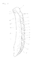
Fig. 1 : A schematic view of a chain drive apparatus according to an embodiment of the present inventionFig. 2 : A perspective view of a chain guide inFig. 1 -
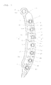
Fig. 3 : A longitudinal sectional view of the chain guide inFig. 2 -
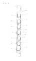
Fig. 4 : A right side view of the chain guide inFig. 3 -
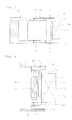
Fig. 5 : A sectional view taken in lines V-V inFig. 3 -
Fig. 6 : An enlarged sectional view of a roller shown inFig. 5 -
Fig. 7 : An exploded front view, showing part of a guide base and a roller -
Fig. 8 : An enlarged sectional view of a roller according to another embodiment according to the present invention -
Fig. 9 : An enlarged sectional view of a roller according to still another embodiment according to the present invention -
Fig. 1 shows a chain drive apparatus which includes chain guides according to an embodiment of the present invention. This chain drive apparatus includes: adrive sprocket 2 which is fixedly attached to acrankshaft 1 of an engine; a drivensprocket 4 which is fixedly attached to acam shaft 3; and achain 5 which is wound around thedrive sprocket 2 and the drivensprocket 4. Thechain 5 which transmits rotation of thecrankshaft 1 to thecam shaft 3, so that valves (not illustrated) in combustion chambers are opened/closed as thecam shaft 3 rotates. - When the engine is operating, the
crankshaft 1 makes rotation in a predetermined direction (clockwise in the figure). Thechain 5, which is driven as thecrankshaft 1 rotates, has a tension side or the side pulled by thedrive sprocket 2, and a slack side or the side leaving thedrive sprocket 2. On the slack side of thechain 5, there are provided achain guide 7 which is supported pivotably around apivot shaft 6; and a chain tensioner 8 which presses thechain guide 7 toward thechain 5. On the other hand, afixed chain guide 9 is provided on the tension side of thechain 5. - The
chain guide 7 is long, extending in an up-down direction along thechain 5, has an upper end region with aninsertion hole 10, into which thepivot shaft 6 is inserted, and therefore is supported pivotably around thepivot shaft 6. Thechain guide 7 has a swinging end, which makes contact with the chain tensioner 8. The chain tensioner 8 urges thechain guide 7 toward thechain 5. - Like the
chain guide 7, thechain guide 9 is also long, extending in an up-down direction along thechain 5. Thechain guide 9 has insertion holes 13 at its upper and lower end regions, and abolt 14 is inserted into each hole. Thebolts 14 are tightened to fix the guide in place. - A difference between the pivoting
chain guide 7 and thefixed chain guide 9 is that the pivotingchain guide 7 has an end region formed with theinsertion hole 10 for insertion of thepivot shaft 6 for pivoting action whereas the fixedchain guide 9 has each of its both end regions formed with theinsertion hole 13 for insertion of the fixingbolt 14. However, this is the only difference, and these two guides are identical with each other in all the other aspects. - For this reason, description hereinafter will cover primarily the pivoting
chain guide 7, and all identical parts in the fixedchain guide 9 will be indicated by using the same reference symbols, without any description thereof. - As shown in
Fig. 2 through Fig. 4 , thechain guide 7 includes aguide base 15 extending in a traveling direction of thechain 5; a plurality ofroller shafts 16 attached to theguide base 15 at an interval along the traveling direction of thechain 5; androllers 17 each supported rotatably by one of theroller shafts 16. - The
guide base 15 has a pair of mutuallyopposed side plates chain 5 for supporting two ends of eachroller shafts 16; and connectingportions 19 each disposed between two mutuallyadjacent roller shafts 16 for connecting theside plates portion 19 has two side ends each fixed to one of theside plates 18, to keep a distance between the twoside plates 18. As shown inFig. 3 andFig. 7 , an opposed surface in eachside plate 18 is provided withcircular recesses 20 for supporting ends of theroller shaft 16; andshaft insertion grooves 21 each leading to one of thecircular recesses 20 from a convex edge of theside plate 18. - As shown in
Fig. 7 , theshaft insertion groove 21 is tapered so that its groove width becomes gradually narrower from the convex edge of theside plate 18 toward thecircular recess 20. Theshaft insertion groove 21 serves as a guide groove when placing an end of theroller shaft 16 into thecircular recess 20. In order to prevent the end of theroller shaft 16 once placed into thecircular recess 20 from coming back to theshaft insertion groove 21, theshaft insertion groove 21 has a narrowed region with a width D1, which is smaller than an inner diameter D2 of thecircular recess 20. - The inner diameter D2 of the
circular recess 20 is slightly smaller than an outer diameter d of theroller shaft 16, so that the end of theroller shaft 16 is press-fitted into thecircular recess 20. - The
guide base 15 may be made by means of injection molding, of a fiber-reinforced synthetic resin material. The synthetic resin may be provided by, e.g., a polyamide (PA) such as nylon 66 or nylon 46. Examples of the reinforcing material to be blended with the synthetic resin includes glass fibers, carbon fibers and aramid fibers. Theguide base 15 may be made of a light metal such as an aluminum alloy or a magnesium alloy. - The
roller shaft 16 is a solid columnar piece made of a steel material such as SUJ2 and SC steel, with its surface wear resistance improved by heat treatment. The heat treatment may be bright hardening or high-frequency hardening. Since theroller shaft 16 is provided by a solid piece of metal rather than a hollow tube, the present invention makes it possible to reduce deterioration in cylindricity on the surface of theroller shaft 16 caused by thermal strain, and therefore makes it possible to reduce rotation noise from theroller 17. - As shown in
Fig. 5 and Fig. 6 , theroller 17 is mounted rotatably around an outer circumference of theroller shaft 16. Theroller 17 has a cylindrical outercircumferential surface 17a, which makes contact with and thereby guides thechain 5. Theroller 17 is provided by a roller bearing which includes: anouter ring 22; a plurality of bearingrollers 23 which are assembled to an inner side of theouter ring 22; and aretainer 24 which holds these bearingrollers 23. - As shown in
Fig. 6 , theouter ring 22 is provided by a shell-type outer ring which is manufactured by means of drawing a steel plate of, e.g., SPC and SCM, into a shape of a cup having astraight region 22A of a constant outer diameter; arounded regions 22B having an arc-shaped section at each end of thestraight region 22A; and aflange region 22C extending radially inward from each of therounded regions 22A. Therounded regions 22B each having an arc-shaped section and formed at the end of theouter ring 22 protect theguide base 15 from wear by reducing aggressiveness to theguide base 15 when there is contact between the end of theouter ring 22 and theguide base 15. - The
outer ring 22 is a heat-treated product having an enhanced hardness due to the heat treatment. The heat treatment ensures wear resistance of the outercircumferential surface 17a. Examples of the heat treatment performed to theouter ring 22 include high-frequency hardening, carburizing and carbonitriding. After the heat treatment, the outercircumferential surface 17a of theouter ring 22 has a cylindricity not greater than 20 µm. - The term cylindricity of the outer
circumferential surface 17a as used herein is defined as the smallest radial distance between two hypothetical concentric cylinders between which all points on the outercircumferential surface 17a are included. - Generally, a shell-type outer ring whose outer diameter is not greater than 25 mm is designed to have a wall thickness of 0.5 mm through 0.8 mm in order to make the drawing process easier. However, according to the present invention, the
outer ring 22 has a wall thickness of 1.0 mm through 3.0 mm. A wall thickness of theouter ring 22 not thinner than 1.0 mm increases stiffness of theouter ring 22, which leads to smaller amount of cylindricity deterioration caused by the heat treatment in the outercircumferential surface 17a, making it possible to obtain a shell-type outer ring which includes an outercircumferential surface 17a of a cylindricity not greater than 20 µm. If theouter ring 22 has a wall thickness greater than 3.0 mm, the drawing process for formation of theouter ring 22 must then be performed in a plurality of steps, resulting in increase in cost of drawing machinery and cost of dies as well. Therefore, the wall thickness of theouter ring 22 is preferably selected to be not greater than 3.0 mm. - The
straight region 22A of theouter ring 22 has an outer diameter between 10 mm through 25 mm. The arc on an outer surface of therounded region 22B has a radius "r" which is between 0.5 mm through 1.5 mm. The radius "r" of the arc not smaller than 0.5 mm efficiently reduces aggressiveness to theside plate 18 when there is contact between the end of theouter ring 22 and theside plate 18 of theguide base 15. Also, by setting the arc radius "r" not greater than 1.5 mm, it becomes possible to give a sufficient length to thestraight region 22A while controlling the overall length of theouter ring 22, enabling to guide thechain 5 stably. -
Fig. 8 shows an embodiment in which theouter ring 22 has a wall thickness t1, theflange regions 22C have a wall thickness t2, and the wall thickness t2 of theflange regions 22C is thinner than the wall thickness t1 of theouter ring 22. In this embodiment, the wall thickness of theflange regions 22C is made thinner than the wall thickness of theouter ring 22, which makes it possible to decrease an end surface r. This increases a width W of theouter ring 22, i.e., the width of contact with thechain 5. The greater width allows stabler contact between theroller 17 and thechain 5 which is travelling at high speeds; in other words, the arrangement enables to increase tracking stability of thechain 5. - The width W of the
outer ring 22 has a specific relationship with a diameter H of theouter ring 22. Specifically, the width W of theouter ring 22 is not smaller than 80 percent the diameter H of theouter ring 22. This setting increases tracking stability of thechain 5. - Reducing the wall thickness t2 of the
flange regions 22C makes it possible to increase the width of theretainer 24 and the length of the bearingrollers 23, which leads to improved load capacity of the roller bearings. If W is not greater than 80 percent of H, bearing rollers in the bearing will have to be insufficiently short, posing a problem that the bearing may tilt and destabilize chain travel when thechain 5 wobbles axially of the bearing. - Since the
outer ring 22, which makes contact with thechain 5, is made of steel, the outer ring has a high level of strength. Also, the steelouter ring 22 should preferably have a higher hardness than thechain 5 for better wear prevention. - Materials for the
outer ring 22 may be SUJ2, SCM, and others which can be hardened by means of heat treatment. - When the
outer ring 22 is hardened by heat treatment, the depth of hardening should preferably be not shallower than 0.05 mm. - The
outer ring 22 may have a finely asperous surface for improved lubricant holding capabilities. - Also, the surface of the
outer ring 22 may receive nitridation process for improved strength. - The
outer ring 22 should preferably have a surface defined by a barrel-like or a straight generatrix so as to avoid localized surface pressure caused by point contact with thechain 5. - The
outer ring 22 can be formed by means of press forming or machining process. - When a press formation method is employed to form the
outer ring 22, it is preferable that the inward facingflange regions 22C at both ends should be formed by edge bending operation after theretainer 24 and bearingrollers 23 have been incorporated, and heat treatment process should be performed after the assembly. - Next, as shown in
Fig. 7 andFig. 8 , once theroller shaft 16 is fitted between theside plates outer ring 22, which represents a part of the roller bearing constituting theroller 17, is lower than end surfaces of theguide base 15. This ensures that thechain 5 is guided to stay between the opposed wall surfaces of theguide base 15 while making contact with theouter rings 22 of the bearings which constitute therollers 17, i.e., the arrangement prevents the movingchain 5 from coming out from between the opposed wall surfaces of theguide base 15. - In addition, it is preferable that the
outer ring 22 of the roller bearing which serves as a constituent part of theroller 17 should give the end surfaces of the guide base 15 a lower height than a position where there is a chain connecting pin which connects chain links with each other as a part of thechain 5. If the height from theouter ring 22 to the end surface of theguide base 15 is higher than the position of the connecting pins which connect the chain plates with each other in thechain 5, the connecting pin makes undesirable contact with the two mutually opposed walls of theguide base 15. - Next,
Fig. 9 is a cross-sectional view of another embodiment of the present invention. In describing this embodiment, any parts and components which are identical with those used in the previous embodiment described thus far will be indicated by the same reference symbols and their description will not be repeated. The following description will be focused on differences. In the present embodiment, as shown inFig. 9 , theroller shaft 16 has alubrication hole 25 at its center, and anoil discharge hole 25a on the side away from thechain 5. With the above, theguide base 15 hasholes 26 which communicate with thelubrication hole 25. By forming thelubrication hole 25 as described, it becomes possible to supply oil to inside of the bearing. This also helps releasing heat. Thedischarge hole 25a of thelubrication hole 25 should preferably made on the side which is away from thechain 5 since this provides smooth supply of oil to the inside of the bearing. Withlubrication hole 25a theroller shaft 16 is now hollow, which provides another advantage of reduced weight. - Next, an operation of the chain drive apparatus which has the above arrangement will be described.
- While the engine is running, the
chain 5 travels around thedrive sprocket 2 and the drivensprocket 4, and thechain 5 transmits a torque from thecrankshaft 1 to thecam shaft 3. In this process, the pivotingchain guide 7 presses thechain 5 with an urging force from the chain tensioner 8, thereby keeping thechain 5 under a constant tension whereas the fixedchain guide 9 reduces chain vibration while keeping an ideal tracking line of thechain 5. - Under this circumstance, each of the
rollers 17 in the chain guides 7, 9 rotates as they make contact with a back-side edge of each chain link which constitutes thechain 5. Since the contact between thechain 5 and the chain guides 7, 9 is rotating contact, travel resistance of thechain 5 is small and therefore torque transmission loss is small. - Generally, an engine crankshaft has a maximum number of revolutions of approximately 8000 rpm. On the other hand, even when the crankshaft is rotating at 3000 rpm, the
rollers 17 are rotating at a much higher speed of approximately 6000 rpm through 9000 rpm. Because therollers 17 are rotating such a high speed when they make contact with thechain 5, even a very small dimensional error in the outercircumferential surfaces 17a of therollers 17 causes fluctuation in contact pressure between thechain 5 and therollers 17. The contact pressure fluctuation causes thechain 5 to vibrate, which then may increase operating noise of thechain 5. - According to the chain guide offered by the present embodiments, however, the outer
circumferential surfaces 17a of therollers 17 have a cylindricity not higher than 20 µm, and therefore the contact pressure between thechain 5 and theroller 17 is less likely to fluctuate when theroller 17 makes contact while rotating at high speeds. Therefore, thechain 5 is less likely to vibrate, i.e., the chain guide is capable of efficiently reducing the operating noise of thechain 5, and is superior in silence. - In the above-described embodiments, the
rollers 17 are provided by roller bearings, and theirouter rings 22 have their outer circumferential surfaces serving as the outercircumferential surface 17a of therollers 17 in order to reduce the weight of therollers 17 thereby minimizing travel resistance of thechain 5. Alternatively, however, a cylindrical member made of resin may be fitted tightly around eachouter ring 22 of the roller bearings, so that the cylindrical member's outer circumferential surface serves as the outercircumferential surface 17a of theroller 17. Also, theouter ring 22 may be provided by a solid-type outer ring formed by means of machining process. Further, the roller bearings may be replaced by bearings of another type. Note that the term roller bearing refers to cylindrical roller bearing and needle roller bearing. - The
chain 5 which transmits rotation of thecrankshaft 1 to thecam shaft 3 may be provided by silent chain, but other choices may include roller chain, and bushing chain which is the roller chain without the rollers. -
- 2
- drive sprocket
- 4
- driven sprocket
- 5
- chain
- 7
- chain guide
- 8
- chain tensioner
- 9
- chain guide
- 15
- guide base
- 16
- roller shaft
- 17
- roller
- 17a
- outer circumferential surface
- 22
- outer ring
- 22A
- straight region
- 22B
- rounded region
- 22C
- flange region
- 23
- bearing roller
- 25
- lubrication hole
- 25a
- discharge hole
- 26
- hole
- r
- arc radius
Claims (13)
- A chain guide comprising: a guide base (15) extending in a traveling direction of a chain (5); a plurality of roller shafts (16) attached to the guide base (15) at an interval along the travelling direction of the chain (5); and rollers (17) each supported rotatably by one of the roller shafts (16) ; each of the rollers (17) having a cylindrical outer circumferential surface (17a) for guiding the chain (5), wherein the outer circumferential surfaces (17a) of the rollers (17) have a cylindricity not greater than 20 µm.
- The chain guide according to Claim 1, wherein the roller (17) is provided by a roller bearing which includes an outer ring (22) and a plurality of bearing rollers (23) incorporated therein, the outer ring (22) of the roller bearing having its outer circumferential surface serving as the outer circumferential surface (17a) of the roller (17), the outer ring (22) being provided by a heat-treated product, the outer ring (22) has a wall thickness not smaller than 1.0 mm.
- The chain guide according to Claim 2, wherein the outer ring (22) is provided by a shell-type outer ring formed by means of drawing a steel plate, the outer ring (22) having a wall thickness not greater than 3.0 mm.
- The chain guide according to Claim 3, wherein the outer ring (22) includes: a straight region (22A) which has a constant outer diameter; a rounded region (22B) having an arc-shaped section at each end of the straight region 22A; and a flange region (22C) extending radially inward from each of the rounded regions (22B).
- The chain guide according to Claim 4, wherein the rounded region (22B) has an arc radius (r) on its outer surface, ranging from 0.5 mm through 1.5 mm.
- The chain guide according to Claim 4 or 5, wherein the outer ring (22) has a wall thickness t1 and the flange region (22C) has a smaller wall thickness t2 than t1.
- The chain guide according to one of Claims 1 through 6, wherein the outer ring (22) has a width W which is not smaller than 80 percent of a diameter H of the outer ring (22),
- The chain guide according to one of Claims 1 through 7, wherein the outer ring (22) has a higher hardness than that of the chain (5).
- The chain guide according to one of Claims 1 through 8, wherein the outer ring (22) is defined by a barrel-like or a straight generatrix.
- The chain guide according to one of Claims 1 through 9, wherein the outer ring (22) has a finely asperous surface for an improved lubricant holding capability.
- The chain guide according to one of Claims 1 through 10, wherein the roller shaft (16) is provided by a heat-treated solid columnar member.
- A chain drive apparatus comprising: a drive sprocket (2) ; a driven sprocket (4) ; a chain (5) wound therearound; a pivotable chain guide (7) disposed on a slack side of the chain (5); and a chain tensioner (8) for pressing the chain guide (7) toward the chain (5) ; wherein the chain guide (7) is provided by one of the chain guides according to Claims 1 through 11.
- The chain drive apparatus according to Claim 12, further comprising a fixed chain guide (9) on a tension side of the chain (5), wherein the chain guide (9) is provided by one of the chain guides according to Claims 1 through 11.
Applications Claiming Priority (3)
| Application Number | Priority Date | Filing Date | Title |
|---|---|---|---|
| JP2011131231A JP5868617B2 (en) | 2011-06-13 | 2011-06-13 | Chain guide and chain tensioner device |
| JP2011165424A JP5917847B2 (en) | 2011-07-28 | 2011-07-28 | Chain guide and chain transmission |
| PCT/JP2012/064789 WO2012173056A1 (en) | 2011-06-13 | 2012-06-08 | Chain guide and chain drive apparatus |
Publications (2)
| Publication Number | Publication Date |
|---|---|
| EP2719922A1 true EP2719922A1 (en) | 2014-04-16 |
| EP2719922A4 EP2719922A4 (en) | 2015-04-08 |
Family
ID=47357045
Family Applications (1)
| Application Number | Title | Priority Date | Filing Date |
|---|---|---|---|
| EP12799729.4A Withdrawn EP2719922A4 (en) | 2011-06-13 | 2012-06-08 | Chain guide and chain drive apparatus |
Country Status (4)
| Country | Link |
|---|---|
| US (1) | US9562593B2 (en) |
| EP (1) | EP2719922A4 (en) |
| CN (1) | CN103620265A (en) |
| WO (1) | WO2012173056A1 (en) |
Families Citing this family (4)
| Publication number | Priority date | Publication date | Assignee | Title |
|---|---|---|---|---|
| JP6278673B2 (en) * | 2013-11-28 | 2018-02-14 | Ntn株式会社 | Chain guide and chain transmission |
| JP6205291B2 (en) * | 2014-02-17 | 2017-09-27 | Ntn株式会社 | Chain drive for camshaft drive |
| JP6265810B2 (en) * | 2014-03-27 | 2018-01-24 | Ntn株式会社 | Chain guide and chain transmission |
| CN109404419A (en) * | 2018-10-25 | 2019-03-01 | 安徽省宁国顺昌机械有限公司 | A kind of arc-shaped guide rail four-point contact ball |
Family Cites Families (82)
| Publication number | Priority date | Publication date | Assignee | Title |
|---|---|---|---|---|
| US68625A (en) * | 1867-09-10 | Improvement in belt-tightener | ||
| US993684A (en) * | 1909-11-11 | 1911-05-30 | Felten & Guilleaume Lahmeyerwe | Transporting mechanism. |
| US1338293A (en) * | 1918-03-23 | 1920-04-27 | Renault Louis | Driving-chain |
| US1579245A (en) * | 1919-11-13 | 1926-04-06 | Gordon R Pennington | Spring suspension for track-laying tractors |
| USRE15894E (en) * | 1921-03-30 | 1924-08-19 | Basfb j | |
| US1499920A (en) * | 1923-01-17 | 1924-07-01 | Norfolk Iron Company | Conveyer |
| US2349281A (en) * | 1942-02-07 | 1944-05-23 | George H Kendall | Pulley bearing |
| US2341273A (en) * | 1942-08-05 | 1944-02-08 | Boeing Aircraft Co | Cable tensioning device |
| US2709371A (en) * | 1951-10-01 | 1955-05-31 | Singer Mfg Co | Universal bobbin winder pulleys |
| US2729110A (en) * | 1953-05-07 | 1956-01-03 | Automatic Steel Products Inc | Sheet metal pulley construction for tooth grip belts |
| US2892206A (en) * | 1953-11-12 | 1959-06-30 | Trico Products Corp | Windshield wiper drive mechanism |
| US2827153A (en) * | 1954-04-07 | 1958-03-18 | Rapids Standard Co Inc | Powered roll conveyors |
| US2964155A (en) * | 1958-12-26 | 1960-12-13 | Leonard B Flowers | Conveyor |
| US3598194A (en) * | 1968-06-10 | 1971-08-10 | Joachim Wappler | Final drive for terrain vehicle |
| US3586142A (en) * | 1969-05-01 | 1971-06-22 | Rapistan Inc | Rail for racks and the like |
| US3950046A (en) * | 1973-08-30 | 1976-04-13 | Industriewerk Schaeffler Ohg | Bearing plate |
| US3888217A (en) * | 1973-09-24 | 1975-06-10 | Charles A Hisserich | Camshaft belt drive for variable valve timing |
| US4078641A (en) * | 1974-04-04 | 1978-03-14 | F.E.I., Inc. | Sanitary roller conveyor |
| US3930323A (en) * | 1974-11-29 | 1976-01-06 | General Motors Corporation | Chain tensioning mechanism for scraper elevator device |
| US3951484A (en) * | 1975-04-14 | 1976-04-20 | Albert G. Nicholson | Roller assembly in a turn chain assembly |
| US4068535A (en) * | 1975-11-10 | 1978-01-17 | David L. Ray | Method and apparatus for controlling the tension of drive belts |
| US4208078A (en) * | 1977-08-29 | 1980-06-17 | Koyo Seiko Company Limited | Cylindrical roller bearings |
| US4213523A (en) * | 1978-09-11 | 1980-07-22 | C. L. Frost & Son, Inc. | Conveyor roller assembly |
| DE8025902U1 (en) * | 1980-09-27 | 1981-01-15 | Skf Kugellagerfabriken Gmbh, 8720 Schweinfurt | Role, in particular tensioning roller for belt drives or the like |
| US4474562A (en) * | 1980-12-03 | 1984-10-02 | Fag Kugelfischer Georg Schafer & Co. | Tensioner for motor-vehicle timing belt |
| US4416648A (en) * | 1981-01-12 | 1983-11-22 | Dyneer Corporation | Belt tensioner |
| US4416647A (en) * | 1981-05-26 | 1983-11-22 | Dayco Corporation | Belt tensioner |
| AU554589B2 (en) * | 1983-05-23 | 1986-08-28 | Fuji Kiko Co. Ltd. | Grooved pulley and manufacturing method therefor |
| JPH0247800Y2 (en) * | 1985-04-30 | 1990-12-14 | ||
| US4723516A (en) * | 1985-11-25 | 1988-02-09 | Slagley Michael W | Valve open duration and timing controller |
| JPS62172847A (en) | 1986-01-27 | 1987-07-29 | Matsushita Electric Works Ltd | Telephone device |
| JPH0430448Y2 (en) * | 1986-04-23 | 1992-07-22 | ||
| CS265980B1 (en) * | 1987-09-02 | 1989-11-14 | Burysek Frantisek | Device for belt pressure with spindleless spinning frame |
| JPH01150070A (en) * | 1987-12-04 | 1989-06-13 | Mitsubishi Electric Corp | Pulley and its manufacture |
| US4969548A (en) * | 1988-04-27 | 1990-11-13 | Kornylak Corporation | Compression set limiting gravity conveyor |
| FR2640714B1 (en) * | 1988-12-16 | 1991-02-08 | Caoutchouc Manuf Plastique | TENSION DEVICE BY TRANSMISSION BY FLEXIBLE LINK WITH DOUBLE ROLLER ON ELASTIC TORSION RING |
| US4892508A (en) * | 1989-06-13 | 1990-01-09 | Robert Ryan | Safety guide support for pivoting pulley |
| US5244439A (en) * | 1992-05-27 | 1993-09-14 | Rogus Thomas E | Roller chain idler replacement |
| US5368403A (en) * | 1993-04-30 | 1994-11-29 | Hewlett-Packard Company | Carriage support system for computer driven printer |
| US5441458A (en) * | 1994-01-14 | 1995-08-15 | Rogus; Thomas E. | Grooved roller chain idler |
| JPH09236157A (en) | 1996-02-29 | 1997-09-09 | Suzuki Motor Corp | Engine chain tensioner device |
| US5848846A (en) * | 1996-07-26 | 1998-12-15 | Ntn Corporation | Shell type needle roller bearing and method of producing the same |
| JP3805449B2 (en) * | 1996-12-19 | 2006-08-02 | 株式会社椿本チエイン | Roller chain travel guide shoe |
| JPH10259451A (en) * | 1997-01-20 | 1998-09-29 | Nippon Seiko Kk | Rolling bearing |
| JP3487540B2 (en) * | 1997-07-01 | 2004-01-19 | 本田技研工業株式会社 | Chain roller structure of chain drive vehicle |
| JP3269011B2 (en) * | 1997-07-28 | 2002-03-25 | 株式会社椿本チエイン | Transmission chain running guide shoe |
| JP3855383B2 (en) * | 1997-08-07 | 2006-12-06 | 株式会社デンソー | Manufacturing method of pulley integrated rotor |
| EP0931737A1 (en) * | 1998-01-22 | 1999-07-28 | Rexnord Marbett S.p.A. | A structure with idle rollers for guide walls of goods conveyors |
| US5967925A (en) * | 1998-03-30 | 1999-10-19 | Ford Global Technologies, Inc. | Pulley with controlled surface irregularity for an internal combustion engine |
| US6371653B2 (en) | 1998-10-07 | 2002-04-16 | Minebea Co., Ltd. | Anti-friction bearing and a motor including such a bearing |
| JP2000130527A (en) * | 1998-10-30 | 2000-05-12 | Nissan Motor Co Ltd | V-belt type continuously variable transmission pulley and continuously variable transmission |
| US6346057B1 (en) * | 1998-11-25 | 2002-02-12 | Klaus Edelmann | Belt tensioning device |
| US6245436B1 (en) * | 1999-02-08 | 2001-06-12 | David Boyle | Surfacing of aluminum bodies by anodic spark deposition |
| JP2000266064A (en) | 1999-03-18 | 2000-09-26 | Komatsu Ltd | Shaft parts for cylindrical and needle roller bearings |
| US6155218A (en) * | 1999-03-22 | 2000-12-05 | The United States Of America As Represented By The Secretary Of The Army | Cam advancing and retarding mechanism |
| US6179740B1 (en) * | 1999-06-02 | 2001-01-30 | Moxee Innovations Corporation | Dual-adjustable belt idler |
| US20010053727A1 (en) * | 2000-06-13 | 2001-12-20 | Eijiro Nakashima | Belt transmission system |
| DE60116888T2 (en) * | 2000-10-03 | 2006-10-26 | The Gates Corp., Denver | DOUBLE, LINEAR BELT TENSION |
| DE10131916A1 (en) * | 2001-07-05 | 2003-01-23 | Muhr & Bender Kg | Tensioning device for traction devices, in particular belt tensioning device |
| EP1443228B1 (en) * | 2001-11-08 | 2011-03-30 | JTEKT Corporation | Bearing device for supporting pinion shaft |
| JP3336337B1 (en) * | 2001-11-14 | 2002-10-21 | 株式会社椿本チエイン | Plastic movable guide for transmission |
| US6866602B2 (en) * | 2002-07-01 | 2005-03-15 | Performance Engineering & Machine Inc. | Belt drive system |
| JP4123883B2 (en) | 2002-09-19 | 2008-07-23 | 株式会社ジェイテクト | Roller bearing manufacturing method |
| JP4376503B2 (en) * | 2002-10-25 | 2009-12-02 | ボルグワーナー・モールステック・ジャパン株式会社 | Sprocket for silent chain and manufacturing method thereof |
| US7114854B2 (en) * | 2002-11-07 | 2006-10-03 | Ntn Corporation | Thrust roller bearing and cage |
| JP2005042879A (en) * | 2003-07-25 | 2005-02-17 | Ntn Corp | Roller bearing with race ring formed of steel plate |
| WO2005028891A1 (en) * | 2003-09-12 | 2005-03-31 | Minebea Co. Ltd. | Fluid dynamic bearing unit |
| US7611289B2 (en) * | 2004-09-24 | 2009-11-03 | Ntn Corporation | Rollers with retainer |
| US7677810B2 (en) * | 2005-01-21 | 2010-03-16 | Ntn Corporation | Bearing washer for thrust bearing and thrust bearing |
| JP4851105B2 (en) * | 2005-03-07 | 2012-01-11 | バンドー化学株式会社 | Belt drive |
| CA2612834A1 (en) * | 2005-06-16 | 2006-12-28 | Moxee Innovations Corporation | Tensioning method |
| DE102006002224A1 (en) * | 2006-01-16 | 2007-07-19 | Schaeffler Kg | Arrangement for protecting a substrate against corrosion, method for its production and pulley |
| US7815533B2 (en) * | 2006-09-18 | 2010-10-19 | Ford Global Technologies | Camshaft drive system for internal combustion engine |
| FR2907526B1 (en) * | 2006-10-20 | 2009-06-26 | Skf Ab | TENDER ROLL OR ROLLER DEVICE. |
| US7866292B2 (en) * | 2008-03-26 | 2011-01-11 | AES Industries Inc | Apparatus and methods for continuous variable valve timing |
| DE102009004562B4 (en) * | 2009-01-14 | 2015-06-03 | Shw Casting Technologies Gmbh | Roller body for a roller for treating a material and method for producing a roller body |
| EP2395261B1 (en) | 2009-02-03 | 2015-10-21 | NTN Corporation | Chain guide and chain tensioner device |
| JP5081843B2 (en) * | 2009-02-03 | 2012-11-28 | Ntn株式会社 | Chain guide and chain tensioner device |
| JP5702528B2 (en) | 2009-09-09 | 2015-04-15 | Ntn株式会社 | Chain guide and chain tensioner device |
| JP2011089553A (en) * | 2009-10-21 | 2011-05-06 | Ntn Corp | Chain guide and chain tensioner device |
| JP2012172810A (en) * | 2011-02-23 | 2012-09-10 | Ntn Corp | Chain guide and chain tensioner device |
| CN103384784B (en) * | 2011-02-23 | 2016-11-16 | Ntn株式会社 | Chain guide and chain stretching device |
-
2012
- 2012-06-08 US US14/125,459 patent/US9562593B2/en not_active Expired - Fee Related
- 2012-06-08 EP EP12799729.4A patent/EP2719922A4/en not_active Withdrawn
- 2012-06-08 WO PCT/JP2012/064789 patent/WO2012173056A1/en not_active Ceased
- 2012-06-08 CN CN201280029391.9A patent/CN103620265A/en active Pending
Also Published As
| Publication number | Publication date |
|---|---|
| US9562593B2 (en) | 2017-02-07 |
| CN103620265A (en) | 2014-03-05 |
| EP2719922A4 (en) | 2015-04-08 |
| US20140274512A1 (en) | 2014-09-18 |
| WO2012173056A1 (en) | 2012-12-20 |
Similar Documents
| Publication | Publication Date | Title |
|---|---|---|
| US9429216B2 (en) | Chain guide and chain tensioner device | |
| EP2679862A1 (en) | Chain guide and chain tensioner device | |
| US9562593B2 (en) | Chain guide and chain drive apparatus | |
| CN103748383B (en) | Chain drives for camshaft drives | |
| EP2679864B1 (en) | Timing chain drive device | |
| EP2738422B1 (en) | Chain guide and chain drive device | |
| WO2013176248A1 (en) | Chain guide and chain transmission device | |
| JP5917847B2 (en) | Chain guide and chain transmission | |
| WO2013011916A1 (en) | Chain guide and chain driving gear | |
| JP5893884B2 (en) | Chain guide and chain transmission | |
| JP6034567B2 (en) | Chain guide and chain transmission | |
| JP5676305B2 (en) | Chain guide and chain tensioner device | |
| JP5706260B2 (en) | Chain guide and chain transmission | |
| JP2012189200A (en) | Chain guide and chain tensioner device | |
| WO2017047491A1 (en) | Chain guide and chain tensioner device | |
| JP2018044635A (en) | Chain guide and chain driving device | |
| JP5706259B2 (en) | Chain guide and chain transmission | |
| JP2012177391A (en) | Chain guide and chain tensioner device | |
| JP2018087603A (en) | Chain guide and chain transmission device | |
| WO2012114845A1 (en) | Chain guide and chain tensioner device |
Legal Events
| Date | Code | Title | Description |
|---|---|---|---|
| PUAI | Public reference made under article 153(3) epc to a published international application that has entered the european phase |
Free format text: ORIGINAL CODE: 0009012 |
|
| 17P | Request for examination filed |
Effective date: 20140110 |
|
| AK | Designated contracting states |
Kind code of ref document: A1 Designated state(s): AL AT BE BG CH CY CZ DE DK EE ES FI FR GB GR HR HU IE IS IT LI LT LU LV MC MK MT NL NO PL PT RO RS SE SI SK SM TR |
|
| DAX | Request for extension of the european patent (deleted) | ||
| RA4 | Supplementary search report drawn up and despatched (corrected) |
Effective date: 20150309 |
|
| RIC1 | Information provided on ipc code assigned before grant |
Ipc: F16H 7/08 20060101AFI20150303BHEP Ipc: F16H 7/18 20060101ALI20150303BHEP |
|
| 17Q | First examination report despatched |
Effective date: 20160629 |
|
| STAA | Information on the status of an ep patent application or granted ep patent |
Free format text: STATUS: THE APPLICATION IS DEEMED TO BE WITHDRAWN |
|
| 18D | Application deemed to be withdrawn |
Effective date: 20190608 |