EP2719575A1 - Vehicle seat with variable backrest shape - Google Patents
Vehicle seat with variable backrest shape Download PDFInfo
- Publication number
- EP2719575A1 EP2719575A1 EP13187686.4A EP13187686A EP2719575A1 EP 2719575 A1 EP2719575 A1 EP 2719575A1 EP 13187686 A EP13187686 A EP 13187686A EP 2719575 A1 EP2719575 A1 EP 2719575A1
- Authority
- EP
- European Patent Office
- Prior art keywords
- strut
- backrest longitudinal
- backrest
- longitudinal strut
- vehicle seat
- Prior art date
- Legal status (The legal status is an assumption and is not a legal conclusion. Google has not performed a legal analysis and makes no representation as to the accuracy of the status listed.)
- Granted
Links
- 239000002184 metal Substances 0.000 claims description 2
- 241000282414 Homo sapiens Species 0.000 description 8
- 241000282412 Homo Species 0.000 description 2
- 239000000463 material Substances 0.000 description 2
- 210000003205 muscle Anatomy 0.000 description 2
- 230000001133 acceleration Effects 0.000 description 1
- 230000001419 dependent effect Effects 0.000 description 1
- 230000000694 effects Effects 0.000 description 1
- 238000005516 engineering process Methods 0.000 description 1
- 210000003041 ligament Anatomy 0.000 description 1
- 230000003387 muscular Effects 0.000 description 1
Images


Classifications
-
- B—PERFORMING OPERATIONS; TRANSPORTING
- B60—VEHICLES IN GENERAL
- B60N—SEATS SPECIALLY ADAPTED FOR VEHICLES; VEHICLE PASSENGER ACCOMMODATION NOT OTHERWISE PROVIDED FOR
- B60N2/00—Seats specially adapted for vehicles; Arrangement or mounting of seats in vehicles
- B60N2/02—Seats specially adapted for vehicles; Arrangement or mounting of seats in vehicles the seat or part thereof being movable, e.g. adjustable
- B60N2/22—Seats specially adapted for vehicles; Arrangement or mounting of seats in vehicles the seat or part thereof being movable, e.g. adjustable the back-rest being adjustable
- B60N2/2222—Seats specially adapted for vehicles; Arrangement or mounting of seats in vehicles the seat or part thereof being movable, e.g. adjustable the back-rest being adjustable the back-rest having two or more parts
-
- B—PERFORMING OPERATIONS; TRANSPORTING
- B60—VEHICLES IN GENERAL
- B60N—SEATS SPECIALLY ADAPTED FOR VEHICLES; VEHICLE PASSENGER ACCOMMODATION NOT OTHERWISE PROVIDED FOR
- B60N2/00—Seats specially adapted for vehicles; Arrangement or mounting of seats in vehicles
- B60N2/24—Seats specially adapted for vehicles; Arrangement or mounting of seats in vehicles for particular purposes or particular vehicles
- B60N2/245—Seats specially adapted for vehicles; Arrangement or mounting of seats in vehicles for particular purposes or particular vehicles for handicapped persons
-
- B—PERFORMING OPERATIONS; TRANSPORTING
- B60—VEHICLES IN GENERAL
- B60N—SEATS SPECIALLY ADAPTED FOR VEHICLES; VEHICLE PASSENGER ACCOMMODATION NOT OTHERWISE PROVIDED FOR
- B60N2/00—Seats specially adapted for vehicles; Arrangement or mounting of seats in vehicles
- B60N2/68—Seat frames
-
- B—PERFORMING OPERATIONS; TRANSPORTING
- B60—VEHICLES IN GENERAL
- B60N—SEATS SPECIALLY ADAPTED FOR VEHICLES; VEHICLE PASSENGER ACCOMMODATION NOT OTHERWISE PROVIDED FOR
- B60N2/00—Seats specially adapted for vehicles; Arrangement or mounting of seats in vehicles
- B60N2/24—Seats specially adapted for vehicles; Arrangement or mounting of seats in vehicles for particular purposes or particular vehicles
- B60N2/26—Seats specially adapted for vehicles; Arrangement or mounting of seats in vehicles for particular purposes or particular vehicles for children
- B60N2/28—Seats readily mountable on, and dismountable from, existing seats or other parts of the vehicle
- B60N2/2884—Seats readily mountable on, and dismountable from, existing seats or other parts of the vehicle with protection systems against abnormal g-forces
-
- B—PERFORMING OPERATIONS; TRANSPORTING
- B60—VEHICLES IN GENERAL
- B60N—SEATS SPECIALLY ADAPTED FOR VEHICLES; VEHICLE PASSENGER ACCOMMODATION NOT OTHERWISE PROVIDED FOR
- B60N2/00—Seats specially adapted for vehicles; Arrangement or mounting of seats in vehicles
- B60N2/24—Seats specially adapted for vehicles; Arrangement or mounting of seats in vehicles for particular purposes or particular vehicles
- B60N2/42—Seats specially adapted for vehicles; Arrangement or mounting of seats in vehicles for particular purposes or particular vehicles the seat constructed to protect the occupant from the effect of abnormal g-forces, e.g. crash or safety seats
- B60N2/4207—Seats specially adapted for vehicles; Arrangement or mounting of seats in vehicles for particular purposes or particular vehicles the seat constructed to protect the occupant from the effect of abnormal g-forces, e.g. crash or safety seats characterised by the direction of the g-forces
- B60N2/4214—Seats specially adapted for vehicles; Arrangement or mounting of seats in vehicles for particular purposes or particular vehicles the seat constructed to protect the occupant from the effect of abnormal g-forces, e.g. crash or safety seats characterised by the direction of the g-forces longitudinal
-
- B—PERFORMING OPERATIONS; TRANSPORTING
- B60—VEHICLES IN GENERAL
- B60N—SEATS SPECIALLY ADAPTED FOR VEHICLES; VEHICLE PASSENGER ACCOMMODATION NOT OTHERWISE PROVIDED FOR
- B60N2/00—Seats specially adapted for vehicles; Arrangement or mounting of seats in vehicles
- B60N2/24—Seats specially adapted for vehicles; Arrangement or mounting of seats in vehicles for particular purposes or particular vehicles
- B60N2/42—Seats specially adapted for vehicles; Arrangement or mounting of seats in vehicles for particular purposes or particular vehicles the seat constructed to protect the occupant from the effect of abnormal g-forces, e.g. crash or safety seats
- B60N2/427—Seats or parts thereof displaced during a crash
- B60N2/42709—Seats or parts thereof displaced during a crash involving residual deformation or fracture of the structure
-
- B—PERFORMING OPERATIONS; TRANSPORTING
- B60—VEHICLES IN GENERAL
- B60N—SEATS SPECIALLY ADAPTED FOR VEHICLES; VEHICLE PASSENGER ACCOMMODATION NOT OTHERWISE PROVIDED FOR
- B60N2/00—Seats specially adapted for vehicles; Arrangement or mounting of seats in vehicles
- B60N2/24—Seats specially adapted for vehicles; Arrangement or mounting of seats in vehicles for particular purposes or particular vehicles
- B60N2/42—Seats specially adapted for vehicles; Arrangement or mounting of seats in vehicles for particular purposes or particular vehicles the seat constructed to protect the occupant from the effect of abnormal g-forces, e.g. crash or safety seats
- B60N2/427—Seats or parts thereof displaced during a crash
- B60N2/42727—Seats or parts thereof displaced during a crash involving substantially rigid displacement
- B60N2/42745—Seats or parts thereof displaced during a crash involving substantially rigid displacement of the back-rest
-
- B—PERFORMING OPERATIONS; TRANSPORTING
- B60—VEHICLES IN GENERAL
- B60N—SEATS SPECIALLY ADAPTED FOR VEHICLES; VEHICLE PASSENGER ACCOMMODATION NOT OTHERWISE PROVIDED FOR
- B60N2/00—Seats specially adapted for vehicles; Arrangement or mounting of seats in vehicles
- B60N2/64—Back-rests or cushions
- B60N2/643—Back-rests or cushions shape of the back-rests
-
- B—PERFORMING OPERATIONS; TRANSPORTING
- B60—VEHICLES IN GENERAL
- B60N—SEATS SPECIALLY ADAPTED FOR VEHICLES; VEHICLE PASSENGER ACCOMMODATION NOT OTHERWISE PROVIDED FOR
- B60N2/00—Seats specially adapted for vehicles; Arrangement or mounting of seats in vehicles
- B60N2/64—Back-rests or cushions
- B60N2/66—Lumbar supports
-
- B—PERFORMING OPERATIONS; TRANSPORTING
- B60—VEHICLES IN GENERAL
- B60N—SEATS SPECIALLY ADAPTED FOR VEHICLES; VEHICLE PASSENGER ACCOMMODATION NOT OTHERWISE PROVIDED FOR
- B60N2/00—Seats specially adapted for vehicles; Arrangement or mounting of seats in vehicles
- B60N2/02—Seats specially adapted for vehicles; Arrangement or mounting of seats in vehicles the seat or part thereof being movable, e.g. adjustable
- B60N2002/0204—Seats specially adapted for vehicles; Arrangement or mounting of seats in vehicles the seat or part thereof being movable, e.g. adjustable characterised by the seat or seat part turning about or moving along a non-standard, particular axis, i.e. an axis different from the axis characterising the conventional movement
- B60N2002/0208—Seats specially adapted for vehicles; Arrangement or mounting of seats in vehicles the seat or part thereof being movable, e.g. adjustable characterised by the seat or seat part turning about or moving along a non-standard, particular axis, i.e. an axis different from the axis characterising the conventional movement the seat or seat part turning about or moving along an inclined axis
-
- B—PERFORMING OPERATIONS; TRANSPORTING
- B60—VEHICLES IN GENERAL
- B60N—SEATS SPECIALLY ADAPTED FOR VEHICLES; VEHICLE PASSENGER ACCOMMODATION NOT OTHERWISE PROVIDED FOR
- B60N2/00—Seats specially adapted for vehicles; Arrangement or mounting of seats in vehicles
- B60N2/02—Seats specially adapted for vehicles; Arrangement or mounting of seats in vehicles the seat or part thereof being movable, e.g. adjustable
- B60N2002/0204—Seats specially adapted for vehicles; Arrangement or mounting of seats in vehicles the seat or part thereof being movable, e.g. adjustable characterised by the seat or seat part turning about or moving along a non-standard, particular axis, i.e. an axis different from the axis characterising the conventional movement
- B60N2002/0212—Seats specially adapted for vehicles; Arrangement or mounting of seats in vehicles the seat or part thereof being movable, e.g. adjustable characterised by the seat or seat part turning about or moving along a non-standard, particular axis, i.e. an axis different from the axis characterising the conventional movement the seat or seat part turning about or moving along a longitudinal axis
-
- B—PERFORMING OPERATIONS; TRANSPORTING
- B60—VEHICLES IN GENERAL
- B60N—SEATS SPECIALLY ADAPTED FOR VEHICLES; VEHICLE PASSENGER ACCOMMODATION NOT OTHERWISE PROVIDED FOR
- B60N2/00—Seats specially adapted for vehicles; Arrangement or mounting of seats in vehicles
- B60N2/02—Seats specially adapted for vehicles; Arrangement or mounting of seats in vehicles the seat or part thereof being movable, e.g. adjustable
- B60N2002/0204—Seats specially adapted for vehicles; Arrangement or mounting of seats in vehicles the seat or part thereof being movable, e.g. adjustable characterised by the seat or seat part turning about or moving along a non-standard, particular axis, i.e. an axis different from the axis characterising the conventional movement
- B60N2002/022—Seats specially adapted for vehicles; Arrangement or mounting of seats in vehicles the seat or part thereof being movable, e.g. adjustable characterised by the seat or seat part turning about or moving along a non-standard, particular axis, i.e. an axis different from the axis characterising the conventional movement the seat or seat part turning about or moving along a vertical axis
Definitions
- the invention relates to a vehicle seat according to the preamble of claim 1.
- Such seats are known in a variety of different configurations.
- the seat frame and the seat back frame of the seat frame can hereby be padded differently formed.
- Such known seats are variable in their seat contour and in their backrest contour, but not sufficiently adapted to the ergonomics of a user, so that the comfort is restricted accordingly and the back of the user is not sufficiently supported in each position by the backrest frame, which optionally can lead to back problems.
- the backrest frame is divided into several mutually pivotable about a vertical axis of rotation sub-segments.
- this movable backrest frame is not optimally adapted to the ergonomics of humans, so that the user of such a vehicle seat may not be able to obtain the necessary seating comfort, but may also have to accept back complaints through the use of such a vehicle seat.
- the present invention has for its object to provide a vehicle seat, which is better adapted to the ergonomics of the human back, especially during rotational movements of the back, and thus at the same time provides increased comfort of the person who uses this vehicle seat.
- a vehicle seat comprising a seat frame with a seat frame and a back frame the latter has a left backrest longitudinal strut and a right backrest longitudinal strut and a lower cross member and an upper cross member, wherein the right and left backrest longitudinal struts against a resistance so pivotally the lower transverse strut are arranged so that the backrest frame is helically deformable.
- the backrest frame is rotated in such a way that the right and left backrest longitudinal struts pivot differently, whereby they remain connected by the upper transverse strut and the entire backrest frame thus deforms helically.
- the pivoting of the left and right backrest longitudinal struts can be done on the one hand such that both are given away in the longitudinal direction of the vehicle seat to the rear but at different angles.
- pivoting is conceivable in which the left or right backrest longitudinal strut is pivoted in the longitudinal direction of the vehicle seat to the front and the other backrest longitudinal strut in the longitudinal direction of the vehicle seat to the rear.
- the backrest frame additionally comprises central backrest longitudinal strut which is pivotally mounted about a substantially horizontal axis on the lower crossbar, wherein the right and left backrest longitudinal struts at least in the region of their upper ends outside a fictitious by a 360 ° rotation the central backrest longitudinal strut formed surface element is arranged.
- the deformation of the backrest frame is optimally adapted to the ergonomics of man, especially in rotational movements of the back or the upper body of a vehicle seat user.
- the individual elements of the backrest frame are assigned to individual elements of the human back and form their movement during the rotation of the back or the upper body of a user from almost identical.
- the middle backrest longitudinal strut is comparable to the spine of humans, while the lower and upper cross strut depict the hip or shoulder axis of the human.
- the left and right backrest longitudinal struts can be compared to the muscular and ligamentous apparatus of the human back.
- a person sitting in such a vehicle seat according to the invention now turns her back or her upper body, while she is supported with her back on the usually provided with a cushion backrest frame, so the shoulder axis of the person rotated with respect to their hip axis, the muscle and Band apparatus together with the spine is twisted helically or torsionally.
- the right, left and middle backrest longitudinal struts twist helically or torsionally against one another, whereby they remain connected by the upper and lower transverse struts.
- the upper transverse strut is divided into a first transverse strut part arranged between the left backrest longitudinal strut and the middle backrest longitudinal strut and a transverse strut part arranged between the right backrest longitudinal strut and the middle backrest longitudinal strut.
- the first cross strut part in receptacles on the left backrest longitudinal strut and the middle backrest longitudinal strut and the second cross strut part in receptacles on the right backrest longitudinal strut and the middle backrest longitudinal strut preferably is held in an articulated manner.
- the entire upper region of the backrest frame has a mobility substantially corresponding to the mobility of the human in the shoulder region, so that movements of the back, in particular torsional and torsional movements of the back can be supported particularly well with the seat according to the invention, which in turn increases the sitting comfort and minimizes the likelihood of back problems.
- the lower transverse strut on the one hand has a central region, on which the middle backrest longitudinal strut is arranged and on the other two of which in the seat longitudinal direction angled portions on which the left backrest longitudinal strut and the right backrest longitudinal strut are located.
- this angle is preferably 45 °.
- the left and right backrest longitudinal strut is fixedly secured to the lower crossbar, wherein the helical rotation is then realized via elastic properties of the left and the right satisfylehenlhacksstrebe over its longitudinal extent.
- the left backrest longitudinal strut is pivotable about an axis on the one angled portion and the right backrest longitudinal strut about a further axis pivotally mounted on the other angled portion.
- the middle backrest longitudinal strut is substantially flat, as formed longitudinally extending component.
- the pressure exerted by the back of a vehicle seat occupant on the seat back frame, over a large area on the center backrest longitudinal strut are discharged without pressure points in the back of the user by small areas, possibly through a cushioning of the backrest frame through, act on the back of the user ,
- the embodiment aims at making the left backrest longitudinal strut substantially flat, with its upper end angled away from the lower end by an angle, and the right-hand backrest longitudinal strut being substantially flat with its upper end opposite the lower one End is angled at the same angle.
- backrest longitudinal strut and the cross braces are diverse, but will usually be made of metal or plastic, since these materials already tested in terms of their dimensional stability and elasticity in many areas in vehicle technology and are adaptable to a variety of requirements, while still meeting the highest security standards.
- the lower cross member may be formed as an integral part of the seat frame in one piece with this or a part thereof.
- the lower cross member is arranged as a separate component on the seat frame, preferably via mounting bracket, in which it is pivotally held about the axis.
- At least the middle backrest longitudinal strut during pivoting builds up a restoring force, preferably a restoring force generated by a spring.
- the right and left backrest longitudinal struts may also provide a restoring force, preferably a restoring force, generated by a spring during their pivoting from their rest position according to a home position, whereby the return of the backrest frame pivoted out of its rest position corresponding to a home position is particularly uniform ,
- a vehicle with at least one vehicle seat described above should also be protected.
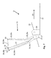
- FIGS. 1 to 4 show various representations of an embodiment of a seat frame 11 of a vehicle seat according to the invention in a basic position, which is taken when the back or the upper body of the vehicle seat user is not twisted.
- the seat frame 11 consists essentially of a seat frame 12 and a pivotally mounted thereto in its inclination Backrest frame 13.
- the backrest frame 13 is arranged on mounting brackets 29 which are fixedly arranged on the seat frame frame 12 or fixed about an axis 21 pivotally.
- the backrest frame 13 consists essentially of a middle, a left and a right backrest longitudinal strut 14, 15 and 16 which are connected to each other by means of a lower and an upper transverse strut 17 and 18.
- the lower transverse strut 17 is formed from a central region 22 and regions 23 and 24 which are angled away in the vehicle longitudinal direction 20 of the vehicle.
- the areas 23 and 24 are angled at an angle 25, which is approximately 45 ° in this embodiment.
- the middle backrest longitudinal strut 14 is arranged pivotable about a horizontal axis 19 at the central region 22 of the lower cross member 17, while the left backrest longitudinal strut 15 at the angled portion 23 about an axis 26 and the right backrest longitudinal strut 16 at the angled portion 24 about an axis 27 is arranged pivotably.
- the upper transverse strut 18 is made in two parts in this embodiment, wherein a first cross brace part 18a connects the middle and left backrest longitudinal struts 14 and 15, while a second cross strut part 18b interconnects the middle and right backrest longitudinal struts 14 and 16.
- the transverse strut parts 18a and 18b are not firmly fixed to the backrest longitudinal struts 14, 15 and 16, but instead are held articulated in receptacles 30, 31, 32 and 33.
- Both the left and the right backrest longitudinal struts 15, 16 are in this case angled.
- the left backrest longitudinal strut 15 can thus be divided into a lower end 15a and an upper end 15b and the right backrest longitudinal strut 16 into a lower end 16a and an upper end 16b.
- the angle 28 between the respective lower and upper end 15a, 16a and 15b, 16b are the same, however, as well as the arrangement of the left and right backrest longitudinal struts 15 and 16 on the lower cross member 17 mirror-symmetrically oriented.
- the right backrest longitudinal strut 16 conceals the left backrest longitudinal strut 15 in this basic position in a side view.
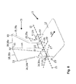
- FIGS. 5 to 8 show now the embodiment of FIGS. 1 to 4 , wherein the backrest frame 13 is pivoted to the left, which corresponds to a back or upper body rotation of the person sitting in the vehicle seat to the right.
- the left backrest longitudinal strut 15 is pivoted about the axis 26, the middle backrest longitudinal strut 14 about the axis 19 and the right backrest longitudinal strut 16 about the axis 27 to the left.
- the right backrest longitudinal strut 16 has moved both with its lower end 16a and with its upper end 16b with respect to the seat longitudinal direction 20 to the rear, while the left backrest longitudinal strut 15 thereby both with its lower end 15a as well its upper end 15b with respect to the seat longitudinal direction 20 has moved forward.
- the entire backrest frame 13 has helically deformed, since the backrest longitudinal struts 14, 15 and 16 fixed to the lower cross member 17 at their pivot points there and therefore are fixed in their orientation there.
- the cross strut 18 is not fixed in its position by their division into two parts and an articulated mounting of the two transverse strut parts 18a and 18b in the receptacles 30 to 33 of the backrest longitudinal struts 14, 15 and 16, but can the movement of the backrest longitudinal struts 14, 15 and 16 during pivoting about the axes 19, 26 and 27 follow.
- FIGS. 9 to 12 show now the embodiment of FIGS. 1 to 4 , wherein the backrest frame 13 is given away to the right, which corresponds to a back or upper body rotation of the person sitting in the vehicle seat to the left.
- the left backrest longitudinal strut 15 is pivoted about the axis 26, the middle backrest longitudinal strut 14 about the axis 19 and the right backrest longitudinal strut 16 about the axis 27 to the right.
- the left backrest longitudinal strut 15 has moved both with its lower end 15a as well as with its upper end 15b with respect to the seat longitudinal direction 20 to the rear, while the right backrest longitudinal strut 16 thereby both with its lower end 16a as well its upper end 16b with respect to the seat longitudinal direction 20 has moved forward.
- the entire backrest frame 13 has helically deformed, since the backrest longitudinal struts 14, 15 and 16 fixed to the lower cross member 17 at their pivot points with the exception of the permitted rotational movement and have fixed orientations in this regard.
Abstract
Description
Die Erfindung betrifft einen Fahrzeugsitz nach dem Oberbegriff des Patentanspruches 1.The invention relates to a vehicle seat according to the preamble of
Derartige Sitze sind in einer Vielzahl verschiedener Ausbildungen bekannt. Der Sitzflächenrahmen und der Rückenlehnenrahmen des Sitzrahmens können hierbei unterschiedlich gebildet gepolstert sein. Solche bekannte Sitze sind zwar in ihrer Sitzkontur und in ihrer Rückenlehnenkontur veränderbar, aber in der Regel nicht der Ergonomie eines Benutzers genügend angepasst, so dass der Komfort entsprechend eingeschränkt und der Rücken des Benutzer nicht in jeder Position ausreichend durch den Rückenlehnenrahmen abgestützt ist, was gegebenenfalls zu Rückenbeschwerden führen kann.Such seats are known in a variety of different configurations. The seat frame and the seat back frame of the seat frame can hereby be padded differently formed. Although such known seats are variable in their seat contour and in their backrest contour, but not sufficiently adapted to the ergonomics of a user, so that the comfort is restricted accordingly and the back of the user is not sufficiently supported in each position by the backrest frame, which optionally can lead to back problems.
So ist beispielsweise aus der
Ein mit einem derartig bewegbaren Rückenlehnenrahmen ausgestatteter Fahrzeugsitz ermöglicht zwar, zum einen hinter dem Sitz liegende Betätigungsorgane für den Benutzer leichter erreichbar zu machen und zum anderen, dass durch ein Drehen des Oberkörpers des Benutzers zur Fahrzeugmitte auch für hinten sitzende Fahrgäste in einem zwei Seitentüren aufweisenden Kraftwagen ein einfacher Durchstieg erreicht wird, ohne dass die vorn Sitzenden gezwungen sind, das Fahrzeug zu verlassen.Although equipped with such a movable backrest frame vehicle seat allows, on the one hand behind the seat lying actuators easier to reach for the user and on the other, that by turning the user's upper body to the center of the vehicle for rear seat passengers in a two side doors having cars a simple access is achieved without the front seat occupants are forced to leave the vehicle.
Allerdings ist dieser bewegbare Rückenlehnenrahmen nicht optimal an die Ergonomie des Menschen angepasst, so dass der Benutzer eines solchen Fahrzeugsitzes unter Umständen nicht den nötigen Sitzkomfort erhalten kann, sondern gegebenenfalls auch Rückenbeschwerden durch die Benutzung eines solchen Fahrzeugsitzes in Kauf nehmen muss.However, this movable backrest frame is not optimally adapted to the ergonomics of humans, so that the user of such a vehicle seat may not be able to obtain the necessary seating comfort, but may also have to accept back complaints through the use of such a vehicle seat.
Demzufolge liegt der vorliegenden Erfindung die Aufgabe zugrunde, einen Fahrzeugsitz zur Verfügung zu stellen, der besser an die Ergonomie des menschlichen Rückens, insbesondere bei Drehbewegungen des Rückens, angepasst ist und somit zugleich einen erhöhten Sitzkomfort derjenigen Person zur Verfügung stellt, die diesen Fahrzeugsitz benutzt.Accordingly, the present invention has for its object to provide a vehicle seat, which is better adapted to the ergonomics of the human back, especially during rotational movements of the back, and thus at the same time provides increased comfort of the person who uses this vehicle seat.
Diese Aufgabe wird durch die Merkmale des Patentanspruches 1 gelöst. Vorteilhafte Ausgestaltungen der Erfindung finden sich in den abhängigen Patentansprüchen.This object is solved by the features of
Kerngedanke der Erfindung ist es, dass bei einem Fahrzeugsitz umfassend einen Sitzrahmen mit einen Sitzflächenrahmen und einem Rückenlehnenrahmen letzterer eine linke Rückenlehnenlängsstrebe und eine rechte Rückenlehnenlängsstrebe sowie eine untere Querstrebe und eine obere Querstrebe aufweist, wobei die die rechte und linke Rückenlehnenlängsstreben gegen einen Widerstand derart verschwenkbar an der unteren Querstrebe angeordnet sind, dass der Rückenlehnenrahmen helixförmig deformierbar ist. Durch diese Ausgestaltung ist es möglich, dass eine im einem solchen erfindungsgemäßen Fahrzeugsitz sitzende Person nun ihren Rücken beziehungsweise ihren Oberkörper, während sie sich mit dem Rücken an dem in der Regel mit einem Polster versehenen Rückenlehnenrahmen abstützt, nach links oder rechts drehen, hat der Rückenlehnerahmen immer Kontakt mit dem Rücken des Benutzers, der sich an diesen somit entlastend abstützt. Der Rückenlehnenrahmen verdreht sich dabei derart, dass die rechte und linke Rückenlehnenlängsstreben unterschiedlich verschwenken, wobei sie durch die obere Querstrebe verbunden bleiben und der gesamte Rückenlehnenrahmen sich somit helixförmig verformt. Das Verschwenken der linken und rechten Rückenlehnenlängsstrebe kann dabei zum einen derart erfolgen, dass beide in Längsrichtung des Fahrzeugsitzes nach hinten aber in unterschiedlichen Winkeln verschenkt werden. Zum anderen ist auch Verschwenken denkbar bei dem die linke oder rechte Rückenlehnenlängsstrebe in Längsrichtung des Fahrzeugsitzes nach vorne und die andere Rückenlehnenlängsstrebe in Längsrichtung des Fahrzeugsitzes nach hinten verschwenkt wird. Dadurch dass dieses Verschwenken jeweils gegen einen Widerstand erfolgt, unterstützt der Rückenlehnenrahmen des erfindungsgemäßen Fahrzeugsitzes den Benutzer beim Drehen des Rücken beziehungsweise des Oberkörpers in seine Ausgangsstellung, da durch den Widerstand eine Rückstellkraft aufbaubar ist, die beim Drehen in die Ausgangsstellung abgebaut wird. Somit ist auch gewährleistet, das der gesamte Rückenlehnenrahmen auch während des Drehens in die Ausgangsstellung den Rücken des Benutzers bei seiner Drehbewegung vollflächig kontaktiert und entlastet, da er die Drehbewegung durch Abbau der Rückstellkraft unterstützt.The core idea of the invention is that in a vehicle seat comprising a seat frame with a seat frame and a back frame the latter has a left backrest longitudinal strut and a right backrest longitudinal strut and a lower cross member and an upper cross member, wherein the right and left backrest longitudinal struts against a resistance so pivotally the lower transverse strut are arranged so that the backrest frame is helically deformable. With this configuration, it is possible that a person sitting in such a vehicle seat according to the invention now turn her back or her torso to the left or right while she is supported with her back on the usually provided with a cushion backrest frame, has the Rückenlehnerahmen always in contact with the back of the user, who is thus relieved of these. The backrest frame is rotated in such a way that the right and left backrest longitudinal struts pivot differently, whereby they remain connected by the upper transverse strut and the entire backrest frame thus deforms helically. The pivoting of the left and right backrest longitudinal struts can be done on the one hand such that both are given away in the longitudinal direction of the vehicle seat to the rear but at different angles. On the other hand also pivoting is conceivable in which the left or right backrest longitudinal strut is pivoted in the longitudinal direction of the vehicle seat to the front and the other backrest longitudinal strut in the longitudinal direction of the vehicle seat to the rear. The fact that this pivoting takes place in each case against a resistance, supports the backrest frame of the invention Vehicle seat the user when turning the back or the upper body in its initial position, as a restoring force can be built up by the resistance, which is reduced when turning into the starting position. Thus, it is also ensured that the entire backrest frame contacted and relieved the user's back during rotation in the starting position during its rotational movement over the entire surface, as he supports the rotational movement by reducing the restoring force.
Nach einem ersten weiteren Gedanken der Erfindung weist der Rückenlehnenrahmen zusätzlich mittlere Rückenlehnenlängsstrebe auf, die um eine im Wesentlichen horizontale Achse verschwenkbar an der unteren Querstrebe befestigt ist, wobei die rechte und linke Rückenlehnenlängsstreben zumindest im Bereich ihrer oberen Enden außerhalb eines fiktiven durch eine 360° Drehung der mittleren Rückenlehnenlängsstrebe gebildeten Flächenelementes angeordnet ist. Durch diese erfindungsgemäße Ausgestaltung des Rückenlehnenrahmens eines Sitzrahmens eines Fahrzeugsitzes ist die Verformung des Rückenlehnenrahmens optimal an die Ergonomie des Menschen, insbesondere bei Drehbewegungen des Rückens beziehungsweise des Oberkörpers eines Fahrzeugsitzbenutzers, angepasst. Die einzelnen Elemente des Rückenlehnenrahmens sind dabei einzelnen Elementen des menschlichen Rückens zugeordnet und bilden deren Bewegung während des Drehens des Rückens beziehungsweise des Oberkörpers eines Benutzers nahezu identisch ab. So ist die mittlere Rückenlehnenlängsstrebe mit der Wirbelsäule des Menschen vergleichbar, während die untere und obere Querstrebe die Hüft- beziehungsweise Schulterachse des Menschen abbilden. Die linke und rechte Rückenlehnenlängsstrebe können mit dem Muskel- und Bandapparat des menschlichen Rückens verglichen werden.According to a first further aspect of the invention, the backrest frame additionally comprises central backrest longitudinal strut which is pivotally mounted about a substantially horizontal axis on the lower crossbar, wherein the right and left backrest longitudinal struts at least in the region of their upper ends outside a fictitious by a 360 ° rotation the central backrest longitudinal strut formed surface element is arranged. By this inventive design of the backrest frame of a seat frame of a vehicle seat, the deformation of the backrest frame is optimally adapted to the ergonomics of man, especially in rotational movements of the back or the upper body of a vehicle seat user. The individual elements of the backrest frame are assigned to individual elements of the human back and form their movement during the rotation of the back or the upper body of a user from almost identical. Thus, the middle backrest longitudinal strut is comparable to the spine of humans, while the lower and upper cross strut depict the hip or shoulder axis of the human. The left and right backrest longitudinal struts can be compared to the muscular and ligamentous apparatus of the human back.
Dreht eine in einem solchen erfindungsgemäßen Fahrzeugsitz sitzende Person nun ihren Rücken beziehungsweise ihren Oberkörper, während sie sich mit dem Rücken an dem in der Regel mit einem Polster versehenen Rückenlehnenrahmen abstützt, so verdreht sich die Schulterachse der Person gegenüber ihrer Hüftachse, wobei der Muskel- und Bandapparat zusammen mit der Wirbelsäule helixartig beziehungsweise torsionsmäßig verdreht wird. In gleicher Weise verdrehen sich bei dem erfindungsgemäßen Fahrzeugsitz die rechte, linke und mittlere Rückenlehnenlängsstrebe helixförmig beziehungsweise torsionsmäßig gegeneinander, wobei diese durch die obere und untere Querstrebe verbunden bleiben. Durch diese ergonomische Ausgestaltung des Rückenlehnenrahmens ist nicht nur der Komfort des Fahrzeugsitzbenutzers gesteigert, vielmehr sind auch durch die dauerhafte und zuverlässige Kontaktierung seines Rückens mit dem in der Regel gepolsterten Rückenlehnerahmens auch während Drehbewegungen des Rückens Rückenbeschwerden vorgebeugt, da der Rückenlehnenrahmen Belastungen aufnehmen kann, die folglich nicht durch den Band- und Muskelapparat des Benutzers abgefangen werden müssen.If a person sitting in such a vehicle seat according to the invention now turns her back or her upper body, while she is supported with her back on the usually provided with a cushion backrest frame, so the shoulder axis of the person rotated with respect to their hip axis, the muscle and Band apparatus together with the spine is twisted helically or torsionally. In the same way, in the vehicle seat according to the invention, the right, left and middle backrest longitudinal struts twist helically or torsionally against one another, whereby they remain connected by the upper and lower transverse struts. This ergonomic design of the backrest frame not only increases the comfort of the vehicle seat user, but also by the durable and reliable Contacting his back with the generally upholstered Rückenlehner frames even during rotational movements of the back prevents back complaints, since the backrest frame can absorb stress, which must therefore not be intercepted by the user's ligament and muscle apparatus.
Nach einem weiteren Gedanken der Erfindung ist die obere Querstrebe in ein zwischen linker Rückenlehnenlängsstrebe und mittlerer Rückenlehnenlängsstrebe angeordnetes erstes Querstrebenteil und ein zwischen rechter Rückenlehnenlängsstrebe und mittlerer Rückenlehnenlängsstrebe angeordnetes Querstrebenteil zweigeteilt. Durch diese Ausgestaltung der Erfindung ist der erfindungsgemäße Fahrzeugsitz nochmals in verbesserter Form der Ergonomie des Menschen angepasst, da es sich nun bei der oberen Querstrebe wie bei der Schulterachse eines Menschen nicht um eine starre Achse handelt.According to a further aspect of the invention, the upper transverse strut is divided into a first transverse strut part arranged between the left backrest longitudinal strut and the middle backrest longitudinal strut and a transverse strut part arranged between the right backrest longitudinal strut and the middle backrest longitudinal strut. By this embodiment of the invention, the vehicle seat according to the invention is again adapted in an improved form of human ergonomics, since it is now not in the upper cross member as in the shoulder axis of a human being is a rigid axis.
Damit die Ergonomie der Schulter nochmals verbessert durch den erfindungsgemäßen Fahrzeugsitz abgebildet werden kann, hat es als vorteilhaft erwiesen, dass das erste Querstrebenteil in Aufnahmen an der linker Rückenlehnenlängsstrebe und der mittlerer Rückenlehnenlängsstrebe und das zweite Querstrebenteil in Aufnahmen an der rechten Rückenlehnenlängsstrebe und der mittlerer Rückenlehnenlängsstrebe vorzugsweise gelenkig gehalten ist. Hierbei weist der gesamte obere Bereich des Rückenlehnenrahmens eine im Wesentlichen der Beweglichkeit des Menschen im Schulterbereich entsprechende Beweglichkeit auf, so dass Bewegungen des Rücken, insbesondere Dreh- und Torsionsbewegungen des Rückens besonders gut mit dem erfindungsgemäßen Sitz unterstützt werden können, was wiederum den Sitzkomfort erhöht und die Wahrscheinlichkeit von Rückenbeschwerden minimiert.So that the ergonomics of the shoulder can be reproduced even more improved by the vehicle seat according to the invention, it has proven to be advantageous that the first cross strut part in receptacles on the left backrest longitudinal strut and the middle backrest longitudinal strut and the second cross strut part in receptacles on the right backrest longitudinal strut and the middle backrest longitudinal strut preferably is held in an articulated manner. Here, the entire upper region of the backrest frame has a mobility substantially corresponding to the mobility of the human in the shoulder region, so that movements of the back, in particular torsional and torsional movements of the back can be supported particularly well with the seat according to the invention, which in turn increases the sitting comfort and minimizes the likelihood of back problems.
Um unterschiedlichen Sitzpositionen von Benutzern des erfindungsgemäßen Fahrzeugsitzes hinsichtlich der Rückenlehenneigung gerecht zu werden, hat es sich bewährt, die untere Querstrebe gegenüber dem Sitzflächenrahmen um eine im Wesentlichen senkrecht zur Sitzlängsrichtung verlaufende horizontale Achse verschwenkbar auszubilden.In order to meet different sitting positions of users of the vehicle seat according to the invention with respect to the backrest inclination, it has proven useful to form the lower cross brace relative to the seat frame frame pivotable about a horizontal axis extending substantially perpendicular to the seat longitudinal direction.
Damit in einfacher Weise die helixförmige beziehungsweise torsionsmäßige Verdrehung realisiert werden kann, weist die untere Querstrebe zum einen einen mittigen Bereich, an dem die mittlere Rückenlehnenlängsstrebe angeordnet ist und zum anderen zwei davon in Sitzlängsrichtung um einen Winkel abgewinkelte Bereiche auf, an denen die linke Rückenlehnenlängsstrebe und die rechte Rückenlehnenlängsstrebe angeordnet sind.So that the helical or torsional rotation can be realized in a simple manner, the lower transverse strut on the one hand has a central region, on which the middle backrest longitudinal strut is arranged and on the other two of which in the seat longitudinal direction angled portions on which the left backrest longitudinal strut and the right backrest longitudinal strut are located.
Um dabei möglichst realistische helixförmige Verdrehungen des Rückenlehnenrahmens verwirklichen zu können und gleichzeitig im Seitenbereich eine ausreichende Abstützwirkung für einen Benutzer des erfindungsgemäßen Fahrzeugsitzes zu erzielen, hat es sich bewährt, dass dieser Winkel vorzugsweise 45° beträgt.In order to be able to realize the most realistic helical rotations of the backrest frame and at the same time to achieve a sufficient support effect for a user of the vehicle seat according to the invention, it has been proven that this angle is preferably 45 °.
Grundsätzlich ist es zwar möglich, dass die linke und rechte Rückenlehnenlängsstrebe fest an der unteren Querstrebe fixiert ist, wobei die helixförmige Verdrehung dann über elastische Eigenschaften der linken und der rechten Rückenlehenlängsstrebe über ihre Längserstreckung realisiert wird. Allerdings bietet es sich an, dass die linke Rückenlehnenlängsstrebe um eine Achse verschwenkbar an dem einen abgewinkelten Bereich und die rechte Rückenlehnenlängsstrebe um eine weitere Achse verschwenkbar an dem anderen abgewinkelten Bereich angeordnet ist.In principle, it is possible that the left and right backrest longitudinal strut is fixedly secured to the lower crossbar, wherein the helical rotation is then realized via elastic properties of the left and the right Rückenlehenlängsstrebe over its longitudinal extent. However, it is advisable that the left backrest longitudinal strut is pivotable about an axis on the one angled portion and the right backrest longitudinal strut about a further axis pivotally mounted on the other angled portion.
Damit eine möglichst komfortable und angenehme Sitzposition erreicht werden kann, ist die mittlere Rückenlehnenlängsstrebe im Wesentlichen flach, als sich längserstreckendes Bauteil ausgebildet. Hierdurch kann der Druck, der von dem Rücken eines Fahrzeugsitzbenutzers auf den Rückenlehnenrahmen ausgeübt wird, großflächig über die mittlere Rückenlehnenlängsstrebe abgeführt werden, ohne dass Druckstellen im Rückenbereich des Benutzers durch kleine Flächenbereiche, eventuell durch eine Polsterung des Rückenlehnenrahmens hindurch, auf den Rücken des Benutzers einwirken.So that the most comfortable and comfortable sitting position can be achieved, the middle backrest longitudinal strut is substantially flat, as formed longitudinally extending component. In this way, the pressure exerted by the back of a vehicle seat occupant on the seat back frame, over a large area on the center backrest longitudinal strut are discharged without pressure points in the back of the user by small areas, possibly through a cushioning of the backrest frame through, act on the back of the user ,
In die gleich Richtung zielt die Ausgestaltung, dass die linke Rückenlehnenlängsstrebe im Wesentlichen flach ausgebildet ist, wobei deren oberes Ende gegenüber dem unteren Ende um einen Winkel abgewinkelt ist, und dass die rechte Rückenlehnenlängsstrebe im Wesentlichen flach ausgebildet ist, wobei deren oberes Ende gegenüber dem unteren Ende um den gleichen Winkel abgewinkelt ist.In the same direction, the embodiment aims at making the left backrest longitudinal strut substantially flat, with its upper end angled away from the lower end by an angle, and the right-hand backrest longitudinal strut being substantially flat with its upper end opposite the lower one End is angled at the same angle.
Die Materialauswahl für die die Rückenlehnenlängsstrebe und die Querstreben ist vielfältig, wird aber in der Regel aus Metall oder Kunststoff erfolgen, da diese Materialen hinsichtlich ihrer Formstabilität und Elastizität in vielen Bereiche in der Fahrzeugtechnik bereits erprobt und auf die unterschiedlichsten Anforderungen anpassbar sind, wobei sie immer noch allerhöchsten Sicherheitsansprüchen beziehungsweise -standards genügen.The choice of material for the backrest longitudinal strut and the cross braces is diverse, but will usually be made of metal or plastic, since these materials already tested in terms of their dimensional stability and elasticity in many areas in vehicle technology and are adaptable to a variety of requirements, while still meeting the highest security standards.
Die untere Querstrebe kann dabei zum einen als integraler Bestandteil des Sitzflächenrahmens einstückig mit diesem beziehungsweise einem Teil davon ausgebildet sein.The lower cross member may be formed as an integral part of the seat frame in one piece with this or a part thereof.
Andererseits ist es natürlich auch denkbar, dass die untere Querstrebe als separates Bauteil an dem Sitzflächenrahmen angeordnet ist, vorzugsweise über Befestigungswinkel, in welchen sie verschwenkbar um die Achse gehalten ist.On the other hand, it is of course also conceivable that the lower cross member is arranged as a separate component on the seat frame, preferably via mounting bracket, in which it is pivotally held about the axis.
Nach einem weiteren Gedanken der Erfindung kann vorgesehen sein, dass zumindest die mittlere Rückenlehenlängsstrebe beim Verschwenken eine Rückstellkraft, vorzugsweise eine durch eine Feder erzeugte Rückstellkraft aufbaut. Durch diese Maßnahme ist sichergestellt, dass der Rückenlehnenrahmen eine Stabilität aufweist, die nicht bereits bei dem geringsten Krafteintrag aus ihrer Ruheposition gemäß einer Grundstellung ausgelenkt wird. Ferner stellt eine solche Rückstellkraft auch sicher, dass die Drehbewegung zurück zur Grundstellung durch den Rückenlehnenrahmen unterstützt wird.According to a further aspect of the invention, it can be provided that at least the middle backrest longitudinal strut during pivoting builds up a restoring force, preferably a restoring force generated by a spring. By this measure, it is ensured that the backrest frame has a stability that is not deflected from its rest position according to a basic position already at the lowest power input. Furthermore, such a restoring force also ensures that the rotational movement is supported back to the normal position by the backrest frame.
Zusätzlich zur mittleren Rückenlehnenlängsstrebe können natürlich auch die rechte und die linke Rückenlehenlängsstrebe während ihres Verschwenken aus ihrer Ruhelage gemäß einer Grundstellung eine Rückstellkraft, vorzugsweise eine durch eine Feder erzeugte Rückstellkraft aufbauen, wodurch die Rückführung des aus seiner Ruhelage entsprechend einer Grundposition heraus verschwenkten Rückenlehnenrahmens besonders gleichmäßig verläuft.Of course, in addition to the central backrest longitudinal strut, the right and left backrest longitudinal struts may also provide a restoring force, preferably a restoring force, generated by a spring during their pivoting from their rest position according to a home position, whereby the return of the backrest frame pivoted out of its rest position corresponding to a home position is particularly uniform ,
Nach einem eigenständigen Gedanken der Erfindung soll auch ein Fahrzeug mit wenigstens einem zuvor beschriebenen Fahrzeugsitz geschützt sein.According to a separate idea of the invention, a vehicle with at least one vehicle seat described above should also be protected.
Weitere Ziele, Vorteile, Merkmale und Anwendungsmöglichkeiten der vorliegenden Erfindung ergeben sich aus der nachfolgenden Beschreibung eines Ausführungsbeispiels anhand der Zeichnung. Dabei bilden alle beschriebenen und/oder bildlich dargestellten Merkmale für sich oder in beliebiger sinnvoller Kombination den Gegenstand der vorliegenden Erfindung, auch unabhängig von ihrer Zusammenfassung in den Ansprüchen oder deren Rückbeziehung.Other objects, advantages, features and applications of the present invention will become apparent from the following description of an embodiment with reference to the drawings. All described and / or illustrated features alone or in any meaningful combination form the subject matter of the present invention, also independent of their summary in the claims or their dependency.
Es zeigen:
- Figur 1:
- ein Ausführungsbeispiel eines Sitzrahmens eines erfindungsgemäßen Fahrzeugsitzes in einer Grundstellung in einer Draufsicht von oben,
- Figur 2:
- der Sitzrahmen gemäß
Figur 1 in einer Ansicht von hinten, - Figur 3:
- der Sitzrahmen gemäß
Figur 1 in einer Seitenansicht, - Figur 4:
- der Sitzrahmen gemäß
Figur 1 in einer perspektivischen Ansicht, - Figur 5:
- das Ausführungsbeispiel des Sitzrahmens gemäß
Figur 1 in einer nach links verschwenkten Stellung in einer Draufsicht von oben, - Figur 6:
- der Sitzrahmen gemäß
Figur 5 in einer Ansicht von hinten, - Figur 7:
- der Sitzrahmen gemäß
Figur 5 in einer Seitenansicht, - Figur 8:
- der Sitzrahmen gemäß
Figur 5 in einer perspektivischen Ansicht, - Figur 9:
- das Ausführungsbeispiel des Sitzrahmens gemäß
Figur 1 in einer nach rechts verschwenkten Stellung in einer Draufsicht von oben, - Figur 10:
- der Sitzrahmen gemäß
Figur 9 in einer Ansicht von hinten, - Figur 11:
- der Sitzrahmen gemäß
Figur 9 in einer Seitenansicht und - Figur 12:
- der Sitzrahmen gemäß
Figur 9 in einer perspektivischen Ansicht.
- FIG. 1:
- An embodiment of a seat frame of a vehicle seat according to the invention in a basic position in a plan view from above,
- FIG. 2:
- the seat frame according to
FIG. 1 in a view from behind, - FIG. 3:
- the seat frame according to
FIG. 1 in a side view, - FIG. 4:
- the seat frame according to
FIG. 1 in a perspective view, - FIG. 5:
- the embodiment of the seat frame according to
FIG. 1 in a pivoted to the left position in a plan view from above, - FIG. 6:
- the seat frame according to
FIG. 5 in a view from behind, - FIG. 7:
- the seat frame according to
FIG. 5 in a side view, - FIG. 8:
- the seat frame according to
FIG. 5 in a perspective view, - FIG. 9:
- the embodiment of the seat frame according to
FIG. 1 in a pivoted to the right position in a plan view from above, - FIG. 10:
- the seat frame according to
FIG. 9 in a view from behind, - FIG. 11:
- the seat frame according to
FIG. 9 in a side view and - FIG. 12:
- the seat frame according to
FIG. 9 in a perspective view.
Die
Der Rückenlehnenrahmen 13 besteht im Wesentlichen aus einer mittleren, einer linken und einer rechten Rückenlehnenlängsstrebe 14, 15 und 16 welche mittels einer unteren und einer oberen Querstrebe 17 und 18 miteinander verbunden sind.The
Die untere Querstrebe 17 ist vorliegend aus einem mittleren Bereich 22 und daran angeordneten in Fahrzeugsitzlängsrichtung 20 abgewinkelten Bereichen 23 und 24 gebildet. Die Bereiche 23 und 24 sind dabei um einen Winkel 25, der in diesem Ausführungsbeispiel in etwa 45° beträgt, abgewinkelt. Die mittlere Rückenlehnenlängsstrebe 14 ist dabei um eine horizontale Achse 19 verschwenkbar an dem mittleren Bereich 22 der unteren Querstrebe 17 angeordnet, während die linke Rückenlehnenlängsstrebe 15 an dem abgewinkelten Bereich 23 um eine Achse 26 und die rechte Rückenlehnenlängsstrebe 16 an dem abgewinkelten Bereich 24 um eine Achse 27 verschwenkbar angeordnet ist.In the present case, the lower transverse strut 17 is formed from a central region 22 and regions 23 and 24 which are angled away in the vehicle
Die obere Querstrebe 18 ist in diesem Ausführungsbeispiel zweigeteilt ausgeführt, wobei ein erstes Querstrebenteil 18a die mittlere und linke Rückenlehnenlängsstrebe 14 und 15 miteinander verbindet, während ein zweites Querstrebenteil 18b die mittlere und rechte Rückenlehnenlängsstrebe 14 und 16 miteinander verbindet. Dabei sind die Querstrebenteile 18a und 18b allerdings nicht an den Rückenlehnenlängsstrebe 14, 15 und 16 fest fixiert sondern in Aufnahmen 30, 31, 32 und 33 gelenkig gehalten.The upper transverse strut 18 is made in two parts in this embodiment, wherein a first cross brace part 18a connects the middle and left backrest
Sowohl die linke als auch die rechte Rückenlehnenlängsstrebe 15, 16 ist hierbei winkelig ausgebildet. Die linke Rückenlehnenlängsstrebe 15 lässt sich somit in ein unteres Ende 15a und ein oberes Ende 15b und die rechte Rückenlehnenlängsstrebe 16 in ein unteres Ende 16a und ein oberes Ende 16b einteilen. Die Winkel 28 zwischen dem jeweiligen unteren und oberen Ende 15a, 16a und 15b, 16b sind dabei gleich, jedoch ebenso wie die Anordnung der linken und rechten Rückenlehnenlängsstrebe 15 und 16 an der unteren Querstrebe 17 spiegelsymmetrisch orientiert.Both the left and the right backrest longitudinal struts 15, 16 are in this case angled. The left backrest longitudinal strut 15 can thus be divided into a lower end 15a and an upper end 15b and the right backrest longitudinal strut 16 into a lower end 16a and an upper end 16b. The
Wie insbesondere der
Die
Wie insbesondere den
Im Gegensatz dazu ist die Querstrebe 18 durch ihre Zweiteilung und einer gelenkigen Lagerung der beiden Querstrebenteile 18a und 18b in den Aufnahmen 30 bis 33 der Rückenlehnenlängsstreben 14, 15 und 16 in Ihrer Position nicht fixiert, sondern kann der Bewegung der Rückenlehnenlängsstreben 14, 15 und 16 während des Verschwenkens um die Achsen 19, 26 und 27 folgen.In contrast, the cross strut 18 is not fixed in its position by their division into two parts and an articulated mounting of the two transverse strut parts 18a and 18b in the
In den Figuren ist eine Federkraftbeaufschlagung der Rückenlehnenstreben 14, 15 und 16 nicht explizit dargestellt. Allerdings wird dadurch vorteilhaft erreicht, dass die verschwenkten Rückenlehnenstreben 14, 15 und 16 aus ihrer verschwenkten Position gemäß den
Die
Wie insbesondere den
- 1111
- Sitzrahmenseat frame
- 1212
- SitzflächenrahmenSeat frame
- 1313
- RückenlehnenrahmenBackrest frame
- 1414
- mittlere Rückenlehnenlängsstrebemiddle backrest longitudinal strut
- 1515
- linke Rückenlehnenlängsstrebeleft backrest longitudinal strut
- 15a15a
- unteres Ende der linken Rückenlehnenlängsstrebelower end of the left backrest longitudinal strut
- 15b15b
- oberes Ende der linken RückenlehnenlängsstrebeUpper end of the left backrest longitudinal strut
- 1616
- rechte Rückenlehnenlängsstreberight backrest longitudinal strut
- 15a15a
- unteres Ende der rechten Rückenlehnenlängsstrebelower end of the right backrest longitudinal strut
- 15b15b
- oberes Ende der rechten Rückenlehnenlängsstrebeupper end of the right backrest longitudinal strut
- 1717
- untere Querstrebelower crossbar
- 1818
- obere Querstrebeupper cross strut
- 18a18a
- QuerstrebenteilCross strut part
- 18b18b
- QuerstrebenteilCross strut part
- 1919
- Achseaxis
- 2020
- SitzlängsrichtungSeat longitudinal direction
- 2121
- Achseaxis
- 2222
- mittiger Bereichcentral area
- 2323
- abgewinkelter Bereichangled area
- 2424
- abgewinkelter Bereichangled area
- 2525
- Winkelangle
- 2626
- Achseaxis
- 2727
- Achseaxis
- 2828
- Winkelangle
- 2929
- Befestigungswinkelmounting brackets
- 3030
- Aufnahmeadmission
- 3131
- Aufnahmeadmission
- 3232
- Aufnahmeadmission
- 3333
- Aufnahmeadmission
Claims (13)
dadurch gekennzeichnet, dass
der Rückenlehnenrahmen (13) mindestens eine linke Rückenlehnenlängsstrebe (15) und mindestens eine rechte Rückenlehnenlängsstrebe (16) sowie eine obere Querstrebe (18) und gegebenenfalls eine untere Querstrebe (17) aufweist, wobei die rechte und die linke Rückenlehnenlängsstrebe (15, 16) gegen einen Widerstand derart verschwenkbar an dem Sitzrahmen (11) angeordnet sind, dass der Rückenlehnenrahmen (13) helixförmig in seine Höhenrichtung deformierbar ist.A vehicle seat comprising a seat frame (11) having a seat frame (12) and a seat back frame (13),
characterized in that
the backrest frame (13) at least one left backrest longitudinal strut (15) and at least one right backrest longitudinal strut (16) and an upper transverse strut (18) and optionally a lower transverse strut (17), wherein the right and left backrest longitudinal struts (15, 16) against a resistance so pivotally mounted on the seat frame (11) are arranged, that the backrest frame (13) is helically deformable in its height direction.
dadurch h gekennzeichnet, dass
der Rückenlehnenrahmen (13) eine mittlere Rückenlehnenlängsstrebe (14) aufweist, die um eine horizontale Achse (19) verschwenkbar an der unteren Querstrebe (17) befestigt ist und wobei die rechte und die linke Rückenlehnenlängsstrebe (15, 16) zumindest im Bereich ihrer oberen Enden (15b, 16b) außerhalb eines fiktiven durch eine 360° Drehung der mittleren Rückenlehnenlängsstrebe (14) gebildeten Flächenelementes angeordnet sind.Vehicle seat according to claim 1,
characterized h that
the backrest frame (13) comprises a central backrest longitudinal strut (14) which is pivotally mounted about a horizontal axis (19) on the lower crossbar (17) and wherein the right and left backrest longitudinal struts (15, 16) at least in the region of their upper ends (15b, 16b) are arranged outside a fictitious by a 360 ° rotation of the central backrest longitudinal strut (14) formed surface element.
dadurch gekennzeichnet, dass
die obere Querstrebe (18) in ein zwischen linker Rückenlehnenlängsstrebe (15) und mittlerer Rückenlehnenlängsstrebe (14) angeordnetes Querstrebenteil (18a) und ein zwischen rechter Rückenlehnenlängsstrebe (16) und mittlerer Rückenlehnenlängsstrebe (14) angeordnetes Querstrebenteil (18b) zweigeteilt ist.Vehicle seat according to claim 1 or 2,
characterized in that
the upper transverse strut (18) is divided into a transverse strut part (18a) arranged between left backrest longitudinal strut (15) and middle backrest longitudinal strut (14) and a transverse strut part (18b) arranged between right backrest longitudinal strut (16) and central backrest longitudinal strut (14).
dadurch gekennzeichnet, dass
das Querstrebeteil (18a) in Aufnahmen (30, 31) an der linker Rückenlehnenlängsstrebe (15) und der mittlerer Rückenlehnenlängsstrebe (14) und das das Querstrebeteil (18b) in Aufnahmen (32, 33) an der rechten Rückenlehnenlängsstrebe (15) und der mittlerer Rückenlehnenlängsstrebe (14), vorzugsweise gelenkig gehalten ist.Vehicle seat according to one of the preceding claims,
characterized in that
the transverse strut part (18a) in receptacles (30, 31) on the left Backrest longitudinal strut (15) and the central backrest longitudinal strut (14) and that the cross strut portion (18b) in receptacles (32, 33) on the right backrest longitudinal strut (15) and the central backrest longitudinal strut (14), preferably articulated.
dadurch gekennzeichnet, dass
die unter Querstrebe (17) gegenüber dem Sitzflächenrahmen (12) um eine im Wesentlichen senkrecht zur Sitzlängsrichtung (20) verlaufende horizontale Achse (21) verschwenkbar ist.Vehicle seat according to one of the preceding claims,
characterized in that
the transverse strut (17) relative to the seat frame (12) about a substantially perpendicular to the seat longitudinal direction (20) extending horizontal axis (21) is pivotable.
dadurch gekennzeichnet, dass
die untere Querstrebe (17) einen mittigen Bereich (22) aufweist, an dem die mittlere Rückenlehnenlängsstrebe (14) angeordnet ist, und zwei davon in Sitzlängsrichtung (20) um einem Winkel (25) abgewinkelte Bereiche (23, 24) aufweist, an denen die linke Rückenlehnenlängsstrebe (15) und die rechte Rückenlehnenlängsstrebe (16) angeordnet sind, wobei der Winkel (25) vorzugsweise 45° beträgt.Vehicle seat according to one of the preceding claims,
characterized in that
the lower transverse strut (17) has a central region (22) on which the central backrest longitudinal strut (14) is arranged, and two of which in the seat longitudinal direction (20) have angled regions (23, 24) at an angle (25) at which the left backrest longitudinal strut (15) and the right backrest longitudinal strut (16) are arranged, wherein the angle (25) is preferably 45 °.
dadurch gekennzeichnet, dass
die linke Rückenlehnenlängsstrebe (15) um eine Achse (26) verschwenkbar an dem abgewinkelten Bereich (23) und die rechte Rückenlehnenlängsstrebe (16) um eine Achse (27) verschwenkbar an dem abgewinkelten Bereich (24) angeordnet ist.Vehicle seat according to one of the preceding claims,
characterized in that
the left backrest longitudinal strut (15) is pivotable about an axis (26) on the angled portion (23) and the right backrest longitudinal strut (16) is pivotable about an axis (27) on the angled portion (24).
dadurch gekennzeichnet, dass
die mittlere Rückenlehnenlängsstrebe (14) im Wesentlichen flach als sich längserstreckendes Bauteil ausgebildet ist.Vehicle seat according to one of the preceding claims,
characterized in that
the middle backrest longitudinal strut (14) is formed substantially flat as a longitudinally extending component.
dadurch gekennzeichnet, dass
die linke Rückenlehnenlängsstrebe (15) im Wesentlichen flach ausgebildet ist, wobei sich deren oberes Ende (15b) gegenüber dem unteren Ende (15a) um einen Winkel (28) abgewinkelt ist, und dass die rechte Rückenlehnenlängsstrebe (16) im Wesentlichen flach ausgebildet ist, wobei sich deren oberes Ende (16b) gegenüber dem unteren Ende (16a) um einen Winkel (28) abgewinkelt ist.Vehicle seat according to one of the preceding claims,
characterized in that
the left backrest longitudinal strut (15) is formed substantially flat, with its upper end (15b) opposite the lower end (15a) at an angle (28) is angled, and that the right backrest longitudinal strut (16) is formed substantially flat, wherein the upper end (16b) relative to the lower end (16a) is angled at an angle (28).
dadurch gekennzeichnet, dass
die Rückenlehnenlängsstrebe (14, 15, 16) und/oder die Querstreben (17, 18) aus Metall oder Kunststoff bestehen.Vehicle seat according to one of the preceding claims,
characterized in that
the backrest longitudinal strut (14, 15, 16) and / or the transverse struts (17, 18) made of metal or plastic.
dadurch gekennzeichnet, dass
die Querstrebe '(17) als integraler Bestanteil des Sitzflächenrahmens (12) einstückig mit diesem beziehungsweise einem Teil davon ausgebildet ist.Vehicle seat according to one of the preceding claims,
characterized in that
the transverse strut '(17) is formed integrally with this or a part thereof as an integral part of the seat frame (12).
dadurch gekennzeichnet, dass
die Querstrebe '(17) als separates Bauteil an dem Sitzflächenrahmen (12) angeordnet ist, vorzugsweise über Befestigungswinkel (29), in welchen sie verschwenkbar um die Achse (21) gehalten ist.Vehicle seat according to one of the preceding claims,
characterized in that
the transverse strut '(17) is arranged as a separate component on the seat surface frame (12), preferably via fastening angles (29), in which it is held pivotably about the axis (21).
Applications Claiming Priority (1)
| Application Number | Priority Date | Filing Date | Title |
|---|---|---|---|
| DE102012109710.0A DE102012109710A1 (en) | 2012-10-11 | 2012-10-11 | Vehicle seat with changeable backrest shape |
Publications (2)
| Publication Number | Publication Date |
|---|---|
| EP2719575A1 true EP2719575A1 (en) | 2014-04-16 |
| EP2719575B1 EP2719575B1 (en) | 2016-02-24 |
Family
ID=49304792
Family Applications (1)
| Application Number | Title | Priority Date | Filing Date |
|---|---|---|---|
| EP13187686.4A Active EP2719575B1 (en) | 2012-10-11 | 2013-10-08 | Vehicle seat with variable backrest shape |
Country Status (4)
| Country | Link |
|---|---|
| US (1) | US9079514B2 (en) |
| EP (1) | EP2719575B1 (en) |
| CN (1) | CN103723056B (en) |
| DE (1) | DE102012109710A1 (en) |
Cited By (4)
| Publication number | Priority date | Publication date | Assignee | Title |
|---|---|---|---|---|
| EP2985177A1 (en) * | 2014-08-13 | 2016-02-17 | Grammer Ag | Vehicle seat with adjustable backrest |
| EP2985178A1 (en) * | 2014-08-13 | 2016-02-17 | Grammer Ag | Vehicle seat with adjustable backrest |
| EP4015300A1 (en) * | 2020-12-18 | 2022-06-22 | Grammer Ag | Vehicle seat with backrest |
| EP4015301A1 (en) * | 2020-12-18 | 2022-06-22 | Grammer Ag | Vehicle seat with backrest |
Families Citing this family (9)
| Publication number | Priority date | Publication date | Assignee | Title |
|---|---|---|---|---|
| CA2852035C (en) | 2011-10-14 | 2020-06-02 | American Track Roadsters, Inc. | Dynamic seating components for wheelchairs |
| JP2017210084A (en) * | 2016-05-25 | 2017-11-30 | トヨタ紡織株式会社 | Back frame structure of vehicular seat |
| JP6512196B2 (en) * | 2016-09-15 | 2019-05-15 | トヨタ自動車株式会社 | Vehicle seat |
| WO2018129030A1 (en) * | 2017-01-05 | 2018-07-12 | Adient Engineering and IP GmbH | A vehicle seat having an adjustable seatback and/or an adjustable cushion |
| EP3576573B1 (en) * | 2017-02-03 | 2021-04-07 | Zhejiang Sunon Furniture Manufacture Co., Ltd. | Chair |
| DE102018116991A1 (en) * | 2018-07-13 | 2020-01-16 | Grammer Ag | Vehicle seat with control device |
| DE102018117000B4 (en) | 2018-07-13 | 2020-04-02 | Grammer Ag | Vehicle seat with control device |
| CN108995567A (en) * | 2018-09-07 | 2018-12-14 | 康海霞 | A kind of new-type new-energy automobile seat |
| US11051624B1 (en) * | 2020-02-27 | 2021-07-06 | Comfordy Co., Ltd. | Twistable chair backrest frame |
Citations (6)
| Publication number | Priority date | Publication date | Assignee | Title |
|---|---|---|---|---|
| DE1258740B (en) * | 1964-07-23 | 1968-01-11 | Stanley Aviation Corp | Seat for vehicles, especially airplanes |
| DE3046049A1 (en) * | 1980-12-06 | 1982-07-15 | Fa. Willibald Grammer, 8450 Amberg | Vehicle seat with all round adjustability for tractors - has backrest swivelling about vertical axis and telescopic armrests |
| EP0347842A1 (en) * | 1988-06-22 | 1989-12-27 | Gebr. Isringhausen | Vehicle seat with a seat back frame |
| DE4405397C1 (en) | 1994-02-21 | 1995-03-16 | Daimler Benz Ag | Vehicle seat with a back rest which is divided in the vertical direction |
| JP2007119202A (en) * | 2005-10-31 | 2007-05-17 | Mitsubishi Heavy Ind Ltd | Seat for forklift |
| WO2008031218A1 (en) * | 2006-09-13 | 2008-03-20 | Intier Automotive Inc. | Deployable bolster for a vehicle seat |
Family Cites Families (25)
| Publication number | Priority date | Publication date | Assignee | Title |
|---|---|---|---|---|
| US5439272A (en) * | 1989-12-26 | 1995-08-08 | Bertrand Faure Automobile | Seat for a vehicle provided with a safety belt with fixation points embarked on the armature of the seat |
| US5509716A (en) * | 1994-11-08 | 1996-04-23 | General Motors Corporation | Vehicle seat with perimeter frame and pelvic catcher |
| FR2736312B1 (en) * | 1995-07-03 | 1997-09-19 | Faure Bertrand Equipements Sa | BACKREST FOR VEHICLE SEAT AND SEAT COMPRISING SUCH A BACKREST |
| US6086153A (en) * | 1997-10-24 | 2000-07-11 | Steelcase Inc. | Chair with reclineable back and adjustable energy mechanism |
| US5918934A (en) * | 1998-11-09 | 1999-07-06 | Johnson Controls Technology Company | Child seat attachment system |
| EP1159153B1 (en) * | 1998-12-14 | 2005-08-31 | Lear Corporation | Vehicle pivotal headrest |
| US6109690A (en) * | 1998-12-18 | 2000-08-29 | Johnson Controls Technology Company | Pivoting seat back |
| DE10012035A1 (en) * | 2000-03-03 | 2001-09-06 | Volkswagen Ag | Motor vehicle seat that can be tilted by actuators commanded by a controller connected to sensors that detect the vehicle attitude, e.g. during sharp cornering the seat can be tilted slightly to compensate |
| DE10152560A1 (en) * | 2000-10-12 | 2003-05-08 | Sven Poppel | Office chair with adjustable seat and backrest has vertically spaced shaped elements at rear of backrest coupled to pivot lever operated by setting device |
| GB0114581D0 (en) * | 2001-06-14 | 2001-08-08 | White Adam | Twister seat |
| US6572190B2 (en) * | 2001-06-15 | 2003-06-03 | Hon Technology Inc. | Lumbar support for a chair |
| US20030127896A1 (en) * | 2001-12-14 | 2003-07-10 | Deimen Michael L. | Chair with lumbar support and conforming back |
| US6767055B1 (en) * | 2002-03-11 | 2004-07-27 | Bostrom Seating, Inc. | Vehicle seat frame and belt assembly |
| US6896324B1 (en) * | 2002-04-19 | 2005-05-24 | Adam Aircraft Industries | Hybrid composite-metal energy absorbing seat |
| FR2840786B1 (en) * | 2002-06-17 | 2005-04-01 | DEFORMABLE BACKREST BY TRANSVERSE ROTATION | |
| AU2003272952A1 (en) * | 2002-10-11 | 2004-05-13 | Kokuyo Furniture Co., Ltd. | Structure of chair backrest |
| DE102005017713B4 (en) * | 2005-04-15 | 2007-10-31 | Grammer Ag | Vehicle seat with deformable backrest |
| JP4747311B2 (en) * | 2005-11-11 | 2011-08-17 | コクヨ株式会社 | Chair |
| US7517024B2 (en) * | 2006-02-03 | 2009-04-14 | Sava Cvek | Post-assembly tension adjustment in elastomeric material applications |
| US8632126B2 (en) * | 2009-01-21 | 2014-01-21 | Ts Tech Co., Ltd. | Vehicle seat |
| DE102009043297B4 (en) * | 2009-09-29 | 2013-04-04 | Grammer Aktiengesellschaft | Vehicle seat with deformable backrest |
| JP5576111B2 (en) * | 2009-12-28 | 2014-08-20 | テイ・エス テック株式会社 | Vehicle seat |
| JP5513212B2 (en) * | 2010-03-30 | 2014-06-04 | 日本発條株式会社 | Vehicle seat back and vehicle seat provided with the same |
| EP2650169A4 (en) * | 2010-12-08 | 2014-06-25 | Ts Tech Co Ltd | Vehicle seat |
| EP2705981B1 (en) * | 2011-05-02 | 2019-04-03 | Toyota Jidosha Kabushiki Kaisha | Vehicle seat and seat back board |
-
2012
- 2012-10-11 DE DE102012109710.0A patent/DE102012109710A1/en not_active Withdrawn
-
2013
- 2013-10-08 EP EP13187686.4A patent/EP2719575B1/en active Active
- 2013-10-10 US US14/050,645 patent/US9079514B2/en active Active
- 2013-10-11 CN CN201310473615.1A patent/CN103723056B/en active Active
Patent Citations (6)
| Publication number | Priority date | Publication date | Assignee | Title |
|---|---|---|---|---|
| DE1258740B (en) * | 1964-07-23 | 1968-01-11 | Stanley Aviation Corp | Seat for vehicles, especially airplanes |
| DE3046049A1 (en) * | 1980-12-06 | 1982-07-15 | Fa. Willibald Grammer, 8450 Amberg | Vehicle seat with all round adjustability for tractors - has backrest swivelling about vertical axis and telescopic armrests |
| EP0347842A1 (en) * | 1988-06-22 | 1989-12-27 | Gebr. Isringhausen | Vehicle seat with a seat back frame |
| DE4405397C1 (en) | 1994-02-21 | 1995-03-16 | Daimler Benz Ag | Vehicle seat with a back rest which is divided in the vertical direction |
| JP2007119202A (en) * | 2005-10-31 | 2007-05-17 | Mitsubishi Heavy Ind Ltd | Seat for forklift |
| WO2008031218A1 (en) * | 2006-09-13 | 2008-03-20 | Intier Automotive Inc. | Deployable bolster for a vehicle seat |
Cited By (10)
| Publication number | Priority date | Publication date | Assignee | Title |
|---|---|---|---|---|
| EP2985177A1 (en) * | 2014-08-13 | 2016-02-17 | Grammer Ag | Vehicle seat with adjustable backrest |
| EP2985178A1 (en) * | 2014-08-13 | 2016-02-17 | Grammer Ag | Vehicle seat with adjustable backrest |
| CN105365611A (en) * | 2014-08-13 | 2016-03-02 | 格拉默股份有限公司 | Vehicle seat with adjustable backrest |
| US9718384B2 (en) | 2014-08-13 | 2017-08-01 | Grammer Ag | Vehicle seat with adjustable backrest |
| US9827881B2 (en) | 2014-08-13 | 2017-11-28 | Grammer Ag | Vehicle seat with adjustable backrest |
| CN105365611B (en) * | 2014-08-13 | 2018-10-26 | 格拉默股份有限公司 | The adjustable automotive seat of backrest |
| EP4015300A1 (en) * | 2020-12-18 | 2022-06-22 | Grammer Ag | Vehicle seat with backrest |
| EP4015301A1 (en) * | 2020-12-18 | 2022-06-22 | Grammer Ag | Vehicle seat with backrest |
| US11679699B2 (en) | 2020-12-18 | 2023-06-20 | Grammer Ag | Vehicle seat having a backrest |
| US11679698B2 (en) | 2020-12-18 | 2023-06-20 | Grammer Ag | Vehicle seat having a backrest |
Also Published As
| Publication number | Publication date |
|---|---|
| US20140103690A1 (en) | 2014-04-17 |
| CN103723056B (en) | 2016-08-03 |
| US9079514B2 (en) | 2015-07-14 |
| CN103723056A (en) | 2014-04-16 |
| DE102012109710A1 (en) | 2014-06-12 |
| EP2719575B1 (en) | 2016-02-24 |
Similar Documents
| Publication | Publication Date | Title |
|---|---|---|
| EP2719575B1 (en) | Vehicle seat with variable backrest shape | |
| EP2106966B1 (en) | Seat with ergo-mechanics | |
| EP1712411B1 (en) | Vehicle seat with a deformable, S-shaped backrest | |
| EP3409144B1 (en) | Chair, specifically conference or office chair and method of producing such a chair | |
| EP1704092B1 (en) | Vehicle seat, particularly an air passenger seat | |
| EP2818359B1 (en) | Vehicle seat and commercial motor vehicle with a vehicle seat | |
| EP2084991B1 (en) | Leaf | |
| DE19743339A1 (en) | Seat and headrest assembly for a vehicle | |
| DE202007007524U1 (en) | Backrest for a chair or armchair and chair or armchair equipped with such a backrest | |
| EP2818358B1 (en) | Vehicle seat and commercial motor vehicle with a vehicle seat | |
| DE8507191U1 (en) | Adjustable vehicle seat | |
| DE102012201318A1 (en) | Lumbar support, backrest, chair and method for adjusting a lumbar support | |
| EP1738955B1 (en) | Vehicle seat with a flexible backrest | |
| DE102015111016B4 (en) | Chair with a synchronous mechanism for synchronous adjustment of the chair carrier when the backrest is swiveled | |
| DE3116459A1 (en) | Chair | |
| DE102004027900B4 (en) | vehicle seat | |
| DE102005035947A1 (en) | Vehicle seat with a deformable backrest | |
| DE19737643A1 (en) | Armrest for seat used in motor vehicle | |
| DE102011100148A1 (en) | Vehicle seat comprises seat part and backrest, where structure of backrest is provided with U-shape, and has two side portions and cross beam in upper area of backrest | |
| DE10126204B4 (en) | Adjustable support device for upholstering a seat and / or deck furniture | |
| DE102019122535A1 (en) | Backrest construction for a vehicle seat | |
| DE10127569A1 (en) | Motor vehicle's seat convertible from adult's seat into child's seat has seat section divided into front and rear section, with front section rotatable on rear section around hinge axis extending at right angles to direction of travel | |
| DE19617401A1 (en) | Motor vehicle seat with tilt adjustment | |
| DE202010015994U1 (en) | Supporting device for upholstering a sitting and / or lying furniture | |
| DE20315140U1 (en) | Device for moving a sofa bed |
Legal Events
| Date | Code | Title | Description |
|---|---|---|---|
| PUAI | Public reference made under article 153(3) epc to a published international application that has entered the european phase |
Free format text: ORIGINAL CODE: 0009012 |
|
| AK | Designated contracting states |
Kind code of ref document: A1 Designated state(s): AL AT BE BG CH CY CZ DE DK EE ES FI FR GB GR HR HU IE IS IT LI LT LU LV MC MK MT NL NO PL PT RO RS SE SI SK SM TR |
|
| AX | Request for extension of the european patent |
Extension state: BA ME |
|
| 17P | Request for examination filed |
Effective date: 20140814 |
|
| RBV | Designated contracting states (corrected) |
Designated state(s): AL AT BE BG CH CY CZ DE DK EE ES FI FR GB GR HR HU IE IS IT LI LT LU LV MC MK MT NL NO PL PT RO RS SE SI SK SM TR |
|
| REG | Reference to a national code |
Ref country code: DE Ref legal event code: R079 Ref document number: 502013001982 Country of ref document: DE Free format text: PREVIOUS MAIN CLASS: B60N0002200000 Ipc: B60N0002660000 |
|
| RIC1 | Information provided on ipc code assigned before grant |
Ipc: B60N 2/22 20060101ALI20150903BHEP Ipc: B60N 2/24 20060101ALI20150903BHEP Ipc: B60N 2/66 20060101AFI20150903BHEP Ipc: B60N 2/42 20060101ALN20150903BHEP Ipc: B60N 2/427 20060101ALN20150903BHEP Ipc: B60N 2/68 20060101ALI20150903BHEP Ipc: B60N 2/02 20060101ALI20150903BHEP Ipc: B60N 2/28 20060101ALN20150903BHEP Ipc: B60N 2/20 20060101ALI20150903BHEP Ipc: B60N 2/64 20060101ALN20150903BHEP |
|
| GRAP | Despatch of communication of intention to grant a patent |
Free format text: ORIGINAL CODE: EPIDOSNIGR1 |
|
| INTG | Intention to grant announced |
Effective date: 20151019 |
|
| GRAS | Grant fee paid |
Free format text: ORIGINAL CODE: EPIDOSNIGR3 |
|
| GRAA | (expected) grant |
Free format text: ORIGINAL CODE: 0009210 |
|
| AK | Designated contracting states |
Kind code of ref document: B1 Designated state(s): AL AT BE BG CH CY CZ DE DK EE ES FI FR GB GR HR HU IE IS IT LI LT LU LV MC MK MT NL NO PL PT RO RS SE SI SK SM TR |
|
| REG | Reference to a national code |
Ref country code: GB Ref legal event code: FG4D Free format text: NOT ENGLISH |
|
| REG | Reference to a national code |
Ref country code: CH Ref legal event code: EP |
|
| REG | Reference to a national code |
Ref country code: AT Ref legal event code: REF Ref document number: 776504 Country of ref document: AT Kind code of ref document: T Effective date: 20160315 |
|
| REG | Reference to a national code |
Ref country code: IE Ref legal event code: FG4D Free format text: LANGUAGE OF EP DOCUMENT: GERMAN |
|
| REG | Reference to a national code |
Ref country code: DE Ref legal event code: R096 Ref document number: 502013001982 Country of ref document: DE |
|
| REG | Reference to a national code |
Ref country code: LT Ref legal event code: MG4D |
|
| REG | Reference to a national code |
Ref country code: NL Ref legal event code: MP Effective date: 20160224 |
|
| PG25 | Lapsed in a contracting state [announced via postgrant information from national office to epo] |
Ref country code: NO Free format text: LAPSE BECAUSE OF FAILURE TO SUBMIT A TRANSLATION OF THE DESCRIPTION OR TO PAY THE FEE WITHIN THE PRESCRIBED TIME-LIMIT Effective date: 20160524 Ref country code: FI Free format text: LAPSE BECAUSE OF FAILURE TO SUBMIT A TRANSLATION OF THE DESCRIPTION OR TO PAY THE FEE WITHIN THE PRESCRIBED TIME-LIMIT Effective date: 20160224 Ref country code: GR Free format text: LAPSE BECAUSE OF FAILURE TO SUBMIT A TRANSLATION OF THE DESCRIPTION OR TO PAY THE FEE WITHIN THE PRESCRIBED TIME-LIMIT Effective date: 20160525 Ref country code: ES Free format text: LAPSE BECAUSE OF FAILURE TO SUBMIT A TRANSLATION OF THE DESCRIPTION OR TO PAY THE FEE WITHIN THE PRESCRIBED TIME-LIMIT Effective date: 20160224 Ref country code: HR Free format text: LAPSE BECAUSE OF FAILURE TO SUBMIT A TRANSLATION OF THE DESCRIPTION OR TO PAY THE FEE WITHIN THE PRESCRIBED TIME-LIMIT Effective date: 20160224 |
|
| PG25 | Lapsed in a contracting state [announced via postgrant information from national office to epo] |
Ref country code: NL Free format text: LAPSE BECAUSE OF FAILURE TO SUBMIT A TRANSLATION OF THE DESCRIPTION OR TO PAY THE FEE WITHIN THE PRESCRIBED TIME-LIMIT Effective date: 20160224 Ref country code: LV Free format text: LAPSE BECAUSE OF FAILURE TO SUBMIT A TRANSLATION OF THE DESCRIPTION OR TO PAY THE FEE WITHIN THE PRESCRIBED TIME-LIMIT Effective date: 20160224 Ref country code: PT Free format text: LAPSE BECAUSE OF FAILURE TO SUBMIT A TRANSLATION OF THE DESCRIPTION OR TO PAY THE FEE WITHIN THE PRESCRIBED TIME-LIMIT Effective date: 20160624 Ref country code: LT Free format text: LAPSE BECAUSE OF FAILURE TO SUBMIT A TRANSLATION OF THE DESCRIPTION OR TO PAY THE FEE WITHIN THE PRESCRIBED TIME-LIMIT Effective date: 20160224 Ref country code: PL Free format text: LAPSE BECAUSE OF FAILURE TO SUBMIT A TRANSLATION OF THE DESCRIPTION OR TO PAY THE FEE WITHIN THE PRESCRIBED TIME-LIMIT Effective date: 20160224 Ref country code: SE Free format text: LAPSE BECAUSE OF FAILURE TO SUBMIT A TRANSLATION OF THE DESCRIPTION OR TO PAY THE FEE WITHIN THE PRESCRIBED TIME-LIMIT Effective date: 20160224 Ref country code: RS Free format text: LAPSE BECAUSE OF FAILURE TO SUBMIT A TRANSLATION OF THE DESCRIPTION OR TO PAY THE FEE WITHIN THE PRESCRIBED TIME-LIMIT Effective date: 20160224 |
|
| REG | Reference to a national code |
Ref country code: FR Ref legal event code: PLFP Year of fee payment: 4 |
|
| PG25 | Lapsed in a contracting state [announced via postgrant information from national office to epo] |
Ref country code: EE Free format text: LAPSE BECAUSE OF FAILURE TO SUBMIT A TRANSLATION OF THE DESCRIPTION OR TO PAY THE FEE WITHIN THE PRESCRIBED TIME-LIMIT Effective date: 20160224 Ref country code: DK Free format text: LAPSE BECAUSE OF FAILURE TO SUBMIT A TRANSLATION OF THE DESCRIPTION OR TO PAY THE FEE WITHIN THE PRESCRIBED TIME-LIMIT Effective date: 20160224 |
|
| REG | Reference to a national code |
Ref country code: DE Ref legal event code: R097 Ref document number: 502013001982 Country of ref document: DE |
|
| PG25 | Lapsed in a contracting state [announced via postgrant information from national office to epo] |
Ref country code: SM Free format text: LAPSE BECAUSE OF FAILURE TO SUBMIT A TRANSLATION OF THE DESCRIPTION OR TO PAY THE FEE WITHIN THE PRESCRIBED TIME-LIMIT Effective date: 20160224 Ref country code: SK Free format text: LAPSE BECAUSE OF FAILURE TO SUBMIT A TRANSLATION OF THE DESCRIPTION OR TO PAY THE FEE WITHIN THE PRESCRIBED TIME-LIMIT Effective date: 20160224 Ref country code: CZ Free format text: LAPSE BECAUSE OF FAILURE TO SUBMIT A TRANSLATION OF THE DESCRIPTION OR TO PAY THE FEE WITHIN THE PRESCRIBED TIME-LIMIT Effective date: 20160224 Ref country code: RO Free format text: LAPSE BECAUSE OF FAILURE TO SUBMIT A TRANSLATION OF THE DESCRIPTION OR TO PAY THE FEE WITHIN THE PRESCRIBED TIME-LIMIT Effective date: 20160224 |
|
| PLBE | No opposition filed within time limit |
Free format text: ORIGINAL CODE: 0009261 |
|
| STAA | Information on the status of an ep patent application or granted ep patent |
Free format text: STATUS: NO OPPOSITION FILED WITHIN TIME LIMIT |
|
| 26N | No opposition filed |
Effective date: 20161125 |
|
| PG25 | Lapsed in a contracting state [announced via postgrant information from national office to epo] |
Ref country code: BE Free format text: LAPSE BECAUSE OF NON-PAYMENT OF DUE FEES Effective date: 20161031 Ref country code: BG Free format text: LAPSE BECAUSE OF FAILURE TO SUBMIT A TRANSLATION OF THE DESCRIPTION OR TO PAY THE FEE WITHIN THE PRESCRIBED TIME-LIMIT Effective date: 20160524 Ref country code: SI Free format text: LAPSE BECAUSE OF FAILURE TO SUBMIT A TRANSLATION OF THE DESCRIPTION OR TO PAY THE FEE WITHIN THE PRESCRIBED TIME-LIMIT Effective date: 20160224 |
|
| REG | Reference to a national code |
Ref country code: CH Ref legal event code: PL |
|
| REG | Reference to a national code |
Ref country code: IE Ref legal event code: MM4A |
|
| PG25 | Lapsed in a contracting state [announced via postgrant information from national office to epo] |
Ref country code: CH Free format text: LAPSE BECAUSE OF NON-PAYMENT OF DUE FEES Effective date: 20161031 Ref country code: LI Free format text: LAPSE BECAUSE OF NON-PAYMENT OF DUE FEES Effective date: 20161031 |
|
| PG25 | Lapsed in a contracting state [announced via postgrant information from national office to epo] |
Ref country code: LU Free format text: LAPSE BECAUSE OF NON-PAYMENT OF DUE FEES Effective date: 20161008 |
|
| REG | Reference to a national code |
Ref country code: FR Ref legal event code: PLFP Year of fee payment: 5 |
|
| PG25 | Lapsed in a contracting state [announced via postgrant information from national office to epo] |
Ref country code: IE Free format text: LAPSE BECAUSE OF NON-PAYMENT OF DUE FEES Effective date: 20161008 |
|
| REG | Reference to a national code |
Ref country code: BE Ref legal event code: MM Effective date: 20161031 |
|
| PG25 | Lapsed in a contracting state [announced via postgrant information from national office to epo] |
Ref country code: CY Free format text: LAPSE BECAUSE OF FAILURE TO SUBMIT A TRANSLATION OF THE DESCRIPTION OR TO PAY THE FEE WITHIN THE PRESCRIBED TIME-LIMIT Effective date: 20160224 Ref country code: HU Free format text: LAPSE BECAUSE OF FAILURE TO SUBMIT A TRANSLATION OF THE DESCRIPTION OR TO PAY THE FEE WITHIN THE PRESCRIBED TIME-LIMIT; INVALID AB INITIO Effective date: 20131008 |
|
| PG25 | Lapsed in a contracting state [announced via postgrant information from national office to epo] |
Ref country code: IS Free format text: LAPSE BECAUSE OF FAILURE TO SUBMIT A TRANSLATION OF THE DESCRIPTION OR TO PAY THE FEE WITHIN THE PRESCRIBED TIME-LIMIT Effective date: 20160224 Ref country code: MK Free format text: LAPSE BECAUSE OF FAILURE TO SUBMIT A TRANSLATION OF THE DESCRIPTION OR TO PAY THE FEE WITHIN THE PRESCRIBED TIME-LIMIT Effective date: 20160224 Ref country code: MT Free format text: LAPSE BECAUSE OF FAILURE TO SUBMIT A TRANSLATION OF THE DESCRIPTION OR TO PAY THE FEE WITHIN THE PRESCRIBED TIME-LIMIT Effective date: 20160224 Ref country code: MC Free format text: LAPSE BECAUSE OF FAILURE TO SUBMIT A TRANSLATION OF THE DESCRIPTION OR TO PAY THE FEE WITHIN THE PRESCRIBED TIME-LIMIT Effective date: 20160224 |
|
| REG | Reference to a national code |
Ref country code: FR Ref legal event code: PLFP Year of fee payment: 6 |
|
| PG25 | Lapsed in a contracting state [announced via postgrant information from national office to epo] |
Ref country code: AL Free format text: LAPSE BECAUSE OF FAILURE TO SUBMIT A TRANSLATION OF THE DESCRIPTION OR TO PAY THE FEE WITHIN THE PRESCRIBED TIME-LIMIT Effective date: 20160224 |
|
| REG | Reference to a national code |
Ref country code: AT Ref legal event code: MM01 Ref document number: 776504 Country of ref document: AT Kind code of ref document: T Effective date: 20181008 |
|
| PG25 | Lapsed in a contracting state [announced via postgrant information from national office to epo] |
Ref country code: AT Free format text: LAPSE BECAUSE OF NON-PAYMENT OF DUE FEES Effective date: 20181008 |
|
| PGFP | Annual fee paid to national office [announced via postgrant information from national office to epo] |
Ref country code: TR Payment date: 20230929 Year of fee payment: 11 |
|
| PGFP | Annual fee paid to national office [announced via postgrant information from national office to epo] |
Ref country code: GB Payment date: 20231025 Year of fee payment: 11 |
|
| PGFP | Annual fee paid to national office [announced via postgrant information from national office to epo] |
Ref country code: IT Payment date: 20231031 Year of fee payment: 11 Ref country code: FR Payment date: 20231023 Year of fee payment: 11 Ref country code: DE Payment date: 20231018 Year of fee payment: 11 |