EP2719570A1 - PTO driveline - Google Patents
PTO driveline Download PDFInfo
- Publication number
- EP2719570A1 EP2719570A1 EP13185024.0A EP13185024A EP2719570A1 EP 2719570 A1 EP2719570 A1 EP 2719570A1 EP 13185024 A EP13185024 A EP 13185024A EP 2719570 A1 EP2719570 A1 EP 2719570A1
- Authority
- EP
- European Patent Office
- Prior art keywords
- clutch
- pto
- driveline
- output shaft
- piston
- Prior art date
- Legal status (The legal status is an assumption and is not a legal conclusion. Google has not performed a legal analysis and makes no representation as to the accuracy of the status listed.)
- Withdrawn
Links
- 239000012530 fluid Substances 0.000 claims description 24
- 230000015572 biosynthetic process Effects 0.000 claims description 10
- 238000001816 cooling Methods 0.000 claims description 6
- 238000005086 pumping Methods 0.000 claims description 6
- 230000001050 lubricating effect Effects 0.000 claims description 5
- 238000005553 drilling Methods 0.000 description 7
- 238000010276 construction Methods 0.000 description 4
- 238000006243 chemical reaction Methods 0.000 description 2
- 238000003754 machining Methods 0.000 description 2
- 230000008878 coupling Effects 0.000 description 1
- 238000010168 coupling process Methods 0.000 description 1
- 238000005859 coupling reaction Methods 0.000 description 1
- 230000001681 protective effect Effects 0.000 description 1
Images






Classifications
-
- B—PERFORMING OPERATIONS; TRANSPORTING
- B60—VEHICLES IN GENERAL
- B60K—ARRANGEMENT OR MOUNTING OF PROPULSION UNITS OR OF TRANSMISSIONS IN VEHICLES; ARRANGEMENT OR MOUNTING OF PLURAL DIVERSE PRIME-MOVERS IN VEHICLES; AUXILIARY DRIVES FOR VEHICLES; INSTRUMENTATION OR DASHBOARDS FOR VEHICLES; ARRANGEMENTS IN CONNECTION WITH COOLING, AIR INTAKE, GAS EXHAUST OR FUEL SUPPLY OF PROPULSION UNITS IN VEHICLES
- B60K25/00—Auxiliary drives
- B60K25/06—Auxiliary drives from the transmission power take-off
-
- B—PERFORMING OPERATIONS; TRANSPORTING
- B60—VEHICLES IN GENERAL
- B60K—ARRANGEMENT OR MOUNTING OF PROPULSION UNITS OR OF TRANSMISSIONS IN VEHICLES; ARRANGEMENT OR MOUNTING OF PLURAL DIVERSE PRIME-MOVERS IN VEHICLES; AUXILIARY DRIVES FOR VEHICLES; INSTRUMENTATION OR DASHBOARDS FOR VEHICLES; ARRANGEMENTS IN CONNECTION WITH COOLING, AIR INTAKE, GAS EXHAUST OR FUEL SUPPLY OF PROPULSION UNITS IN VEHICLES
- B60K17/00—Arrangement or mounting of transmissions in vehicles
- B60K17/28—Arrangement or mounting of transmissions in vehicles characterised by arrangement, location, or type of power take-off
Definitions
- This invention relates to power take-off (PTO) drivelines for use in agricultural and industrial vehicles.
- a vehicle PTO driveline in which a PTO input shaft drives a PTO clutch which when engaged drives a PTO output shaft via reduction gearing, the driveline being characterised in that a limited rotational free play device is provided in the driveline on the input side of the reduction gearing which allows limited manual rotation of the output shaft by a vehicle operator when the output shaft is not driven by the clutch.
- the PTO clutch may include a brake which has a brake disc rotatable with the output shaft and which, when the clutch is not engaged, is held against a braking surface on a housing of the driveline to stop rotation of the PTO output shaft.
- the brake disc may be splined to an output member of the clutch by lugs which engage circumferentially extending cut outs in the output member, the limited rotation of the PTO output shaft being limited by the circumferential extent of the cut outs.
- the brake disc and the lugs may be of a simple flat construction and the free play function can be provided simply by machining circumferentially long cut outs in the output member of the clutch.
- the brake and free play function can be provided simply, cheaply and efficiently.
- the clutch may be engaged by a hydraulic piston and disengaged by a spring, the spring automatically applying the brake when the hydraulic piston is not pressurised.
- the clutch may be coaxial with the input shaft and the output shaft may rotate about an axis laterally displaced from the axis of rotation of the input shaft and may be connected thereto by the reduction gearing.
- the PTO input shaft may drive a PTO wet clutch which when engaged drives a PTO output shaft, the driveline being characterised in that an eccentric formation on the input shaft oscillates a pumping piston when the input shaft rotates, the oscillating piston pumping cooling/lubricating fluid to the wet clutch.
- the cooling/lubricating fluid may be pumped around a circuit which includes a fluid reservoir provided by part of a housing which encloses the driveline.
- the oscillating piston may draw the fluid from the reservoir via a non-return valve arrangement.
- the piston may be connected with the eccentric formation by a ring which surrounds the eccentric formation and a hollow tube which is attached to the ring and which carries the piston at a lower end, the piston oscillating inside a chamber when the input shaft rotates, said chamber being connected with the fluid reservoir and the oscillating piston pumping the fluid along the hollow tube into the ring which then delivers the fluid into internal passages in the input shaft from where the fluid flows to the wet clutch.
- the wet clutch may be a multi-plate clutch engaged by an end pressure plate which is moved hydraulically or mechanically to engage the clutch and thus drive the PTO output shaft.
- the driveline may be arranged so that when the PTO wet clutch is disengaged flow of fluid to the wet clutch is cut-off to reduce drag across the wet clutch.
- a driveline in accordance with the present invention is particularly suitable for use as the front PTO driveline of a tractor due to its inherent simplicity and compactness.
- a front PTO driveline 10 for an agricultural tractor has an input shaft 11 supported within a housing 25 which is in three parts via bearings 25a.
- Shaft 11 drives a PTO wet clutch 12 which, when engaged, drives a PTO output shaft 13, supported in housing 25 via bearings 25b.
- Shaft 13 is driven from clutch 12 via meshing gears 14 and 15 and has the customary removable protective cover 13a.
- Wet clutch 12 includes a first set of annular clutch plates 16 which are splined at their inner peripheries to a piston 17 which is in turn splined at 18 to input shaft 11.
- a second set of annular clutch plates 19 are interleaved with plates 16 and are splined at their outer peripheries to an outer clutch housing 20 which has an output tube 21 which surrounds input shaft 11 and which is splined to gear 14.
- Clutch plates 16 and 19 are located between a reaction ring 22 which is splined onto housing 20 and a pressure plate 23 which is splined onto piston 17.
- Clutch 12 is engaged by an actuating piston 24 which is displaceable relative to outer housing 25 by pressurising a hydraulic chamber 26.
- Actuating piston 24 presses on piston 17 via bearing 27 and is prevented from rotating relative to housing 25 by pin 28.
- a spring 29 acts between piston 17 and an abutment ring 30 located on shaft 11 by a split ring 30a to move piston 17 to the right relative to shaft 11 to disengage the clutch when chamber 26 is not pressurised.
- clutch 12 is engaged by pressurising chamber 26 which moves pistons 24 and 17 to the left and thus causes pressure plate 23 to press plates 16 and 19 into contact with each other against reaction ring 22 to transmit drive from input shaft 11 to output tube 21 and hence to gears 14 and 15 thus driving PTO output shaft 13.
- the wet clutch 12 is provided with a supply of pressurised cooling/lubricating fluid by a reciprocating piston 31 which is carried on the lower end of a pipe 32 connected to a ring 33 which surrounds an eccentric formation 34 formed on or carried by the input shaft 11. Ring 33 is sealed to formation 34 by seals 33a.
- Piston 31 draws fluid into chamber 31 a via non-return valve 35 and then forces fluid up tube 32 via a further non-return valve 36. Fluid exits from the top of tube 32 into the interior of ring 33 and hence via radial drillings 37 in the eccentric formation 33 into an axial passage 38 in the input shaft 11.
- control edge 17a (see Figure 3A ) of piston 17 blocks the oil flow into drilling 40 so that oil enters the chamber housing spring 29.
- the centrifugal forces throw the oil through the holes 17b into the area between clutch plates 16 and clutch plates 19 to provide optimum cooling.
- Fluid also flows from passage 38 to bearings 25a via drilling 39a.
- the PTO drive arrangement is also provided with a brake facility to brake the PTO output shaft 13 when the clutch 12 is disengaged.
- This brake takes the form of a brake disc 50 which is splined by lugs 51 for rotation with housing 20.
- Brake disc 50 is located between housing 25 and a flange 52 provided on actuating piston 24 so that when chamber 26 is not pressurised spring 29 forces piston 17 to bring braking disc 50 into contact with housing 25 and thus hold housing 20 and hence output shaft 13 against rotation .
- Lugs 51 engage circumferentially long cut outs 53 (see Figures 6 and 7 ) in the end of housing 20.
- lugs 51 can be of a less robust construction.
- the brake disc 50 and the lugs 51 is of a simple flat construction and the free play function can be provided simply by machining circumferentially long cut outs 53 in the end of housing 20.
- the brake and free play function can be provided simply, cheaply and efficiently.
Landscapes
- Engineering & Computer Science (AREA)
- Chemical & Material Sciences (AREA)
- Combustion & Propulsion (AREA)
- Transportation (AREA)
- Mechanical Engineering (AREA)
- Hydraulic Clutches, Magnetic Clutches, Fluid Clutches, And Fluid Joints (AREA)
- Arrangement And Driving Of Transmission Devices (AREA)
Abstract
Description
- This invention relates to power take-off (PTO) drivelines for use in agricultural and industrial vehicles.
- It is well known in , for example, agricultural tractors to provide a PTO driveline at the front or rear of the tractor which includes a clutch which when engaged delivers power to a PTO output shaft to drive an implement or attachment at the front or rear of the tractor.
- In order to be able to easily connect an implement or attachment to such a PTO driveline it is known to provide a so-called free play device which allows the operator to manually rotate the output shaft through a limited angle in order to align the drive splines on the output shaft with the drive splines on the input to the implement or attachment.
- It is an object of the present invention to provide an improved form of PTO driveline which is suitable for use in an agricultural tractor and which provides a simple and efficient free play device.
- Thus according to the present invention there is provided a vehicle PTO driveline in which a PTO input shaft drives a PTO clutch which when engaged drives a PTO output shaft via reduction gearing, the driveline being characterised in that a limited rotational free play device is provided in the driveline on the input side of the reduction gearing which allows limited manual rotation of the output shaft by a vehicle operator when the output shaft is not driven by the clutch.
- The PTO clutch may include a brake which has a brake disc rotatable with the output shaft and which, when the clutch is not engaged, is held against a braking surface on a housing of the driveline to stop rotation of the PTO output shaft.
- The brake disc may be splined to an output member of the clutch by lugs which engage circumferentially extending cut outs in the output member, the limited rotation of the PTO output shaft being limited by the circumferential extent of the cut outs.
- By locating the free play device on the input side of the reduction gearing the torque experienced by lugs is reduced since the output member of the clutch is rotating at a higher speed than the output shaft. Thus lugs can be of a less robust construction.
- Also the brake disc and the lugs may be of a simple flat construction and the free play function can be provided simply by machining circumferentially long cut outs in the output member of the clutch. Thus the brake and free play function can be provided simply, cheaply and efficiently.
- The clutch may be engaged by a hydraulic piston and disengaged by a spring, the spring automatically applying the brake when the hydraulic piston is not pressurised.
- The clutch may be coaxial with the input shaft and the output shaft may rotate about an axis laterally displaced from the axis of rotation of the input shaft and may be connected thereto by the reduction gearing.
- The PTO input shaft may drive a PTO wet clutch which when engaged drives a PTO output shaft, the driveline being characterised in that an eccentric formation on the input shaft oscillates a pumping piston when the input shaft rotates, the oscillating piston pumping cooling/lubricating fluid to the wet clutch.
- The cooling/lubricating fluid may be pumped around a circuit which includes a fluid reservoir provided by part of a housing which encloses the driveline.
- The oscillating piston may draw the fluid from the reservoir via a non-return valve arrangement.
- The piston may be connected with the eccentric formation by a ring which surrounds the eccentric formation and a hollow tube which is attached to the ring and which carries the piston at a lower end, the piston oscillating inside a chamber when the input shaft rotates, said chamber being connected with the fluid reservoir and the oscillating piston pumping the fluid along the hollow tube into the ring which then delivers the fluid into internal passages in the input shaft from where the fluid flows to the wet clutch.
- The wet clutch may be a multi-plate clutch engaged by an end pressure plate which is moved hydraulically or mechanically to engage the clutch and thus drive the PTO output shaft.
- The driveline may be arranged so that when the PTO wet clutch is disengaged flow of fluid to the wet clutch is cut-off to reduce drag across the wet clutch.
- A driveline in accordance with the present invention is particularly suitable for use as the front PTO driveline of a tractor due to its inherent simplicity and compactness.
- One embodiment of the present invention as applied to an agricultural tractor driveline will now be described, by way of example only, with reference to the accompanying drawings in which:-
-
Figure 1 shows a longitudinal section on line A-A ofFigure 2 ; -
Figure 1A shows part ofFigure 3 on a larger scale for clarity; -
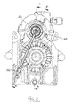
Figure 2 shows a transverse section on the line C-C ofFigure 1 ; -
Figure 3 shows a longitudinal section on the line B-B ofFigure 2 ; -
Figure 3A shows part ofFigure 3 on a larger scale for clarity; -
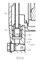
Figure 4 shows detail D ofFigure 3 on a larger scale; -
Figure 5 shows detail E ofFigure 1 on a larger scale; -
Figure 6 shows a perspective view of a wet clutch assembly used in the driveline, and -
Figure 7 shows an end view of the wet clutch assembly ofFigure 6 viewed in the direction of the arrow Z ofFigure 6 . - Referring to the drawings, a
front PTO driveline 10 for an agricultural tractor has aninput shaft 11 supported within ahousing 25 which is in three parts viabearings 25a. Shaft 11 drives a PTOwet clutch 12 which, when engaged, drives aPTO output shaft 13, supported inhousing 25 viabearings 25b. Shaft 13 is driven fromclutch 12 via meshinggears protective cover 13a. -
Wet clutch 12 includes a first set ofannular clutch plates 16 which are splined at their inner peripheries to apiston 17 which is in turn splined at 18 to inputshaft 11. A second set ofannular clutch plates 19 are interleaved withplates 16 and are splined at their outer peripheries to anouter clutch housing 20 which has anoutput tube 21 which surroundsinput shaft 11 and which is splined togear 14.Clutch plates reaction ring 22 which is splined ontohousing 20 and apressure plate 23 which is splined ontopiston 17. Clutch 12 is engaged by an actuatingpiston 24 which is displaceable relative toouter housing 25 by pressurising ahydraulic chamber 26. Actuatingpiston 24 presses onpiston 17 via bearing 27 and is prevented from rotating relative tohousing 25 bypin 28. Aspring 29 acts betweenpiston 17 and anabutment ring 30 located onshaft 11 by asplit ring 30a to movepiston 17 to the right relative toshaft 11 to disengage the clutch whenchamber 26 is not pressurised. - Thus
clutch 12 is engaged by pressurisingchamber 26 which movespistons pressure plate 23 to pressplates reaction ring 22 to transmit drive frominput shaft 11 tooutput tube 21 and hence togears PTO output shaft 13. - In accordance with the Applicant's co-pending
UK patent application No. 1218234.1 wet clutch 12 is provided with a supply of pressurised cooling/lubricating fluid by a reciprocatingpiston 31 which is carried on the lower end of apipe 32 connected to aring 33 which surrounds aneccentric formation 34 formed on or carried by theinput shaft 11. Ring 33 is sealed toformation 34 byseals 33a. - As can be seen from
Figures 2 and4 , asformation 34 rotates withshaft 11piston 31 oscillates inside achamber 31 a formed in the lower part ofhousing 25 and thus draws fluid from areservoir 25c, having an oil level L, formed by the interior of the lower part ofhousing 25. - Piston 31 draws fluid into
chamber 31 a vianon-return valve 35 and then forces fluid uptube 32 via a furthernon-return valve 36. Fluid exits from the top oftube 32 into the interior ofring 33 and hence viaradial drillings 37 in theeccentric formation 33 into anaxial passage 38 in theinput shaft 11. - If the clutch is not engaged, oil passes from
passage 38 viaradial drilling 39 inshaft 11 and drillings 40 inabutment ring 30 into the area where theclutch plates 16/19 are housed. The oil can flow to the passage 41 c on the left side ofplates 16/19 and hence return to thereservoir 25c viadrilling 42a without excessive drag losses (see arrows X inFigure 1A ). - If the clutch is engaged,
control edge 17a (seeFigure 3A ) ofpiston 17 blocks the oil flow into drilling 40 so that oil enters thechamber housing spring 29. The centrifugal forces throw the oil through theholes 17b into the area betweenclutch plates 16 andclutch plates 19 to provide optimum cooling. After passing theclutch plates 16/19, oil exits through the outer periphery of the clutch housing viaholes 41 a and returns toreservoir 25c viaclearance 42 and drilling 42a (see arrows Y inFig. 3A ). - Fluid also flows from
passage 38 tobearings 25a viadrilling 39a. - In accordance with the present invention the PTO drive arrangement is also provided with a brake facility to brake the
PTO output shaft 13 when theclutch 12 is disengaged. This brake takes the form of abrake disc 50 which is splined bylugs 51 for rotation withhousing 20.Brake disc 50 is located betweenhousing 25 and aflange 52 provided on actuatingpiston 24 so that whenchamber 26 is not pressurisedspring 29forces piston 17 to bringbraking disc 50 into contact withhousing 25 and thus holdhousing 20 and henceoutput shaft 13 against rotation .Lugs 51 engage circumferentially long cut outs 53 (seeFigures 6 and7 ) in the end ofhousing 20. Thus whenPTO output shaft 13 is held stationary by the above brake arrangement it is still possible for the tractor operator to rotate the output shaft by hand due through a limited angle (typically 120 degrees) due to the rotational free play between thelugs 51 and theends 53a of thecut outs 53. This free play greatly facilitates coupling of the output shaft to the implement or attachment which the PTO shaft is to drive. - By locating the free play device on the input side of the reduction gearing 14 and 15 the torque experienced by
lugs 51 is reduced sincehousing 20 is rotating at a higher speed than theoutput shaft 13. Thuslugs 51 can be of a less robust construction. - Also the
brake disc 50 and thelugs 51 is of a simple flat construction and the free play function can be provided simply by machining circumferentially long cutouts 53 in the end ofhousing 20. Thus the brake and free play function can be provided simply, cheaply and efficiently.
Claims (11)
- A vehicle PTO driveline in which a PTO input shaft drives a PTO clutch which when engaged drives a PTO output shaft via reduction gearing, the driveline being characterised in that a limited rotational free play device is provided in the driveline on the input side of the reduction gearing which allows limited manual rotation of the output shaft by a vehicle operator when the output shaft is not driven by the clutch.
- A driveline according to claim 1 in which the PTO clutch includes a brake which has a brake disc rotatable with the output shaft and which, when the clutch is not engaged, is held against a braking surface on a housing of the driveline to stop rotation of the PTO output shaft.
- A driveline according to claim 2 in which the brake disc is splined to an output member of the clutch by lugs which engage circumferentially extending cut outs in the output member, the limited rotation of the PTO output shaft being limited by the circumferential extent of the cut outs.
- A driveline according to claim any one of claims 1 to 3 in which the clutch is engaged by a hydraulic piston and disengaged by a spring, the spring automatically applying the brake when the hydraulic piston is not pressurised.
- A driveline according to any one of claims 1 to 4 in which the clutch is coaxial with the input shaft and the output shaft rotates about an axis laterally displaced from the axis of rotation of the input shaft and is connected thereto by the reduction gearing.
- A driveline according to any one of claims 1 to 5 in which the clutch is a wet clutch and an eccentric formation on the input shaft oscillates a pumping piston when the input shaft rotates, the oscillating piston pumping cooling/lubricating fluid to the wet clutch.
- A driveline according to claim 6 in which the cooling/lubricating fluid is pumped around a circuit which includes a fluid reservoir provided by part of a housing which encloses the driveline.
- A driveline according to claim 7 in which the oscillating piston draws the fluid from the reservoir via a non-return valve arrangement.
- A driveline according to claim 7 or 8 in which the piston is connected with the eccentric formation by a ring which surrounds the eccentric formation and a hollow tube which is attached to the ring and which carries the piston at a lower end, the piston oscillating inside a chamber when the input shaft rotates, said chamber being connected with the fluid reservoir and the oscillating piston pumping the fluid along the hollow tube into the ring which then delivers the fluid into internal passages in the input shaft from where the fluid flows to the wet clutch.
- A driveline according to any one of claims 6 to 9 in which the wet clutch is a multi-plate clutch engaged by an end pressure plate which is moved hydraulically or mechanically to engage the clutch and thus drive the PTO output shaft.
- A driveline according to any one of claims 1 to 5 in which when the PTO wet clutch is disengaged flow of fluid to the wet clutch is cut-off to reduce drag across the wet clutch.
Applications Claiming Priority (1)
| Application Number | Priority Date | Filing Date | Title |
|---|---|---|---|
| GBGB1218237.4A GB201218237D0 (en) | 2012-10-11 | 2012-10-11 | PTO drivelines |
Publications (1)
| Publication Number | Publication Date |
|---|---|
| EP2719570A1 true EP2719570A1 (en) | 2014-04-16 |
Family
ID=47324598
Family Applications (1)
| Application Number | Title | Priority Date | Filing Date |
|---|---|---|---|
| EP13185024.0A Withdrawn EP2719570A1 (en) | 2012-10-11 | 2013-09-18 | PTO driveline |
Country Status (3)
| Country | Link |
|---|---|
| US (1) | US20140102228A1 (en) |
| EP (1) | EP2719570A1 (en) |
| GB (1) | GB201218237D0 (en) |
Cited By (2)
| Publication number | Priority date | Publication date | Assignee | Title |
|---|---|---|---|---|
| CN104191970A (en) * | 2014-09-11 | 2014-12-10 | 陕西法士特汽车传动集团有限责任公司 | Power takeoff |
| EP2719912A3 (en) * | 2012-10-11 | 2018-01-03 | AGCO International GmbH | PTO Drivelines |
Families Citing this family (11)
| Publication number | Priority date | Publication date | Assignee | Title |
|---|---|---|---|---|
| US20120207620A1 (en) | 2007-07-12 | 2012-08-16 | Odyne Systems, LLC. | Hybrid vehicle drive system and method and idle reduction system and method |
| US8408341B2 (en) | 2007-07-12 | 2013-04-02 | Odyne Systems, Llc | Hybrid vehicle drive system and method and idle reduction system and method |
| US12330657B2 (en) | 2011-12-02 | 2025-06-17 | Power Technology Holdings Llc | Hybrid vehicle drive system and method for fuel reduction during idle |
| US11225240B2 (en) * | 2011-12-02 | 2022-01-18 | Power Technology Holdings, Llc | Hybrid vehicle drive system and method for fuel reduction during idle |
| ES2569199T3 (en) * | 2012-01-10 | 2016-05-09 | Parker-Hannifin Corporation | PTO unit with integrated connector |
| US9752624B2 (en) * | 2014-10-22 | 2017-09-05 | Deere & Company | Tractor/implement PTO connection mechanism |
| PL3416847T3 (en) * | 2016-02-18 | 2024-01-22 | Twin Disc, Inc. | Hydraulic power take-off with brake disconnect system for industrial drives |
| CN107882855B (en) * | 2016-09-29 | 2021-07-09 | 乔治费歇尔金属成型科技(昆山)有限公司 | Transfer case ring gear shaft, manufacturing method thereof and apparatus including the same |
| CN109253194B (en) * | 2018-10-23 | 2023-10-27 | 天津大学 | Mechanical clutch and brake function system and clutch and brake function conversion method |
| CN109442017B (en) * | 2018-12-19 | 2024-01-02 | 绍兴前进齿轮箱有限公司 | Rear axle transmission system of multifunctional cleaning vehicle |
| GB202019371D0 (en) * | 2020-12-09 | 2021-01-20 | Agco Int Gmbh | Compression roll housing |
Citations (2)
| Publication number | Priority date | Publication date | Assignee | Title |
|---|---|---|---|---|
| GB2277358A (en) * | 1993-04-19 | 1994-10-26 | Kubota Kk | Clutch/brake combination |
| US20020079180A1 (en) * | 1998-10-16 | 2002-06-27 | Mohan Sankar K. | Hydraulic coupling with multi-function control valve |
Family Cites Families (9)
| Publication number | Priority date | Publication date | Assignee | Title |
|---|---|---|---|---|
| US3209872A (en) * | 1962-04-19 | 1965-10-05 | Int Harvester Co | Independent power take-off with clutch and anti-creep brake |
| US3698524A (en) * | 1971-02-19 | 1972-10-17 | Int Harvester Co | I.p.t.o brake unit |
| DE2924939C2 (en) * | 1979-06-21 | 1985-05-23 | Zahnradfabrik Friedrichshafen Ag, 7990 Friedrichshafen | PTO drive for motor vehicles that can be used in agriculture and / or construction |
| US6142274A (en) * | 1996-12-30 | 2000-11-07 | Dana Corporation | Power take-off unit with selectively engaged brake |
| GB2336640B (en) * | 1998-04-21 | 2003-02-19 | Agco Gmbh & Co | Auxiliary drive for utility vehicle & method of operation thereof |
| US6497313B1 (en) * | 2001-03-28 | 2002-12-24 | Parker Hannifin Corporation | Power take-off unit with automatically actuated drag brake |
| US20040211274A1 (en) * | 2003-04-25 | 2004-10-28 | Seipold John M. | Power takeoff assembly and method |
| WO2005033554A1 (en) * | 2003-10-01 | 2005-04-14 | Yanmar Co.,Ltd. | Travel working machine |
| US7684918B2 (en) * | 2007-07-12 | 2010-03-23 | Deere & Company | PTO brake control system |
-
2012
- 2012-10-11 GB GBGB1218237.4A patent/GB201218237D0/en not_active Ceased
-
2013
- 2013-09-18 EP EP13185024.0A patent/EP2719570A1/en not_active Withdrawn
- 2013-10-11 US US14/051,736 patent/US20140102228A1/en not_active Abandoned
Patent Citations (2)
| Publication number | Priority date | Publication date | Assignee | Title |
|---|---|---|---|---|
| GB2277358A (en) * | 1993-04-19 | 1994-10-26 | Kubota Kk | Clutch/brake combination |
| US20020079180A1 (en) * | 1998-10-16 | 2002-06-27 | Mohan Sankar K. | Hydraulic coupling with multi-function control valve |
Cited By (2)
| Publication number | Priority date | Publication date | Assignee | Title |
|---|---|---|---|---|
| EP2719912A3 (en) * | 2012-10-11 | 2018-01-03 | AGCO International GmbH | PTO Drivelines |
| CN104191970A (en) * | 2014-09-11 | 2014-12-10 | 陕西法士特汽车传动集团有限责任公司 | Power takeoff |
Also Published As
| Publication number | Publication date |
|---|---|
| GB201218237D0 (en) | 2012-11-28 |
| US20140102228A1 (en) | 2014-04-17 |
Similar Documents
| Publication | Publication Date | Title |
|---|---|---|
| EP2719912B1 (en) | PTO Drivelines | |
| US20140102228A1 (en) | PTO Drivelines | |
| DE102008033434B4 (en) | Vehicle powertrain with direct power source | |
| KR101774673B1 (en) | Lubricating structure for friction engagement element of automatic transmission | |
| DE102005040771A1 (en) | Powertrain of a hybrid vehicle | |
| US9297426B2 (en) | Power take-off with remotely mounted clutch assembly and lubricated spline | |
| KR102658685B1 (en) | Clutch device for hybrid drive system | |
| CN103052831A (en) | Work vehicle | |
| EP2802473B1 (en) | Power take-off unit (pto) with integral shifter | |
| CN106715178A (en) | Power take-off unit with hydraulic disconnect | |
| EP2116743B1 (en) | Variable belt drive | |
| EP2981727B1 (en) | A hydraulic system with a dog clutch | |
| DE102005040770A1 (en) | Drive section for use in hybrid vehicle, has rotor support with bearing support at radial inner side of rotor support, and bearing support directly supported in oil pump housing by pivot bearing and directly driving impeller of oil pump | |
| EP0952027B1 (en) | Auxiliary drive for utility vehicle and method of operation thereof | |
| US9746062B2 (en) | Power transmission device for vehicle | |
| US9482290B2 (en) | Transmission gear engagement mechanism and method of operation | |
| CN107848412B (en) | Clutch group for power output device | |
| US2725963A (en) | Clutch-control driving mechanism | |
| CN220248724U (en) | Wet clutch PTO | |
| US2627763A (en) | Power transmission | |
| JP2003194196A (en) | Power take-out device | |
| JP2017150499A (en) | Power transmission device | |
| JP2003240016A (en) | Outer ring structure of hydraulic clutch | |
| SE437247B (en) | HYDRAULIC POWER TRANSMISSION DEVICE FOR DIESEL LOCK |
Legal Events
| Date | Code | Title | Description |
|---|---|---|---|
| PUAI | Public reference made under article 153(3) epc to a published international application that has entered the european phase |
Free format text: ORIGINAL CODE: 0009012 |
|
| AK | Designated contracting states |
Kind code of ref document: A1 Designated state(s): AL AT BE BG CH CY CZ DE DK EE ES FI FR GB GR HR HU IE IS IT LI LT LU LV MC MK MT NL NO PL PT RO RS SE SI SK SM TR |
|
| AX | Request for extension of the european patent |
Extension state: BA ME |
|
| 17P | Request for examination filed |
Effective date: 20141016 |
|
| RBV | Designated contracting states (corrected) |
Designated state(s): AL AT BE BG CH CY CZ DE DK EE ES FI FR GB GR HR HU IE IS IT LI LT LU LV MC MK MT NL NO PL PT RO RS SE SI SK SM TR |
|
| STAA | Information on the status of an ep patent application or granted ep patent |
Free format text: STATUS: THE APPLICATION IS DEEMED TO BE WITHDRAWN |
|
| 18D | Application deemed to be withdrawn |
Effective date: 20141017 |