EP2719367A2 - Face massaging device - Google Patents
Face massaging device Download PDFInfo
- Publication number
- EP2719367A2 EP2719367A2 EP12811402.2A EP12811402A EP2719367A2 EP 2719367 A2 EP2719367 A2 EP 2719367A2 EP 12811402 A EP12811402 A EP 12811402A EP 2719367 A2 EP2719367 A2 EP 2719367A2
- Authority
- EP
- European Patent Office
- Prior art keywords
- mask
- battery
- vibration
- massage device
- drive
- Prior art date
- Legal status (The legal status is an assumption and is not a legal conclusion. Google has not performed a legal analysis and makes no representation as to the accuracy of the status listed.)
- Granted
Links
Images


Classifications
-
- A—HUMAN NECESSITIES
- A61—MEDICAL OR VETERINARY SCIENCE; HYGIENE
- A61H—PHYSICAL THERAPY APPARATUS, e.g. DEVICES FOR LOCATING OR STIMULATING REFLEX POINTS IN THE BODY; ARTIFICIAL RESPIRATION; MASSAGE; BATHING DEVICES FOR SPECIAL THERAPEUTIC OR HYGIENIC PURPOSES OR SPECIFIC PARTS OF THE BODY
- A61H23/00—Percussion or vibration massage, e.g. using supersonic vibration; Suction-vibration massage; Massage with moving diaphragms
- A61H23/02—Percussion or vibration massage, e.g. using supersonic vibration; Suction-vibration massage; Massage with moving diaphragms with electric or magnetic drive
-
- A—HUMAN NECESSITIES
- A45—HAND OR TRAVELLING ARTICLES
- A45D—HAIRDRESSING OR SHAVING EQUIPMENT; EQUIPMENT FOR COSMETICS OR COSMETIC TREATMENTS, e.g. FOR MANICURING OR PEDICURING
- A45D44/00—Other cosmetic or toiletry articles, e.g. for hairdressers' rooms
- A45D44/22—Face shaping devices, e.g. chin straps; Wrinkle removers, e.g. stretching the skin
-
- A—HUMAN NECESSITIES
- A61—MEDICAL OR VETERINARY SCIENCE; HYGIENE
- A61H—PHYSICAL THERAPY APPARATUS, e.g. DEVICES FOR LOCATING OR STIMULATING REFLEX POINTS IN THE BODY; ARTIFICIAL RESPIRATION; MASSAGE; BATHING DEVICES FOR SPECIAL THERAPEUTIC OR HYGIENIC PURPOSES OR SPECIFIC PARTS OF THE BODY
- A61H23/00—Percussion or vibration massage, e.g. using supersonic vibration; Suction-vibration massage; Massage with moving diaphragms
- A61H23/006—Percussion or tapping massage
-
- A—HUMAN NECESSITIES
- A61—MEDICAL OR VETERINARY SCIENCE; HYGIENE
- A61H—PHYSICAL THERAPY APPARATUS, e.g. DEVICES FOR LOCATING OR STIMULATING REFLEX POINTS IN THE BODY; ARTIFICIAL RESPIRATION; MASSAGE; BATHING DEVICES FOR SPECIAL THERAPEUTIC OR HYGIENIC PURPOSES OR SPECIFIC PARTS OF THE BODY
- A61H23/00—Percussion or vibration massage, e.g. using supersonic vibration; Suction-vibration massage; Massage with moving diaphragms
- A61H23/02—Percussion or vibration massage, e.g. using supersonic vibration; Suction-vibration massage; Massage with moving diaphragms with electric or magnetic drive
- A61H23/0254—Percussion or vibration massage, e.g. using supersonic vibration; Suction-vibration massage; Massage with moving diaphragms with electric or magnetic drive with rotary motor
- A61H23/0263—Percussion or vibration massage, e.g. using supersonic vibration; Suction-vibration massage; Massage with moving diaphragms with electric or magnetic drive with rotary motor using rotating unbalanced masses
-
- A—HUMAN NECESSITIES
- A61—MEDICAL OR VETERINARY SCIENCE; HYGIENE
- A61H—PHYSICAL THERAPY APPARATUS, e.g. DEVICES FOR LOCATING OR STIMULATING REFLEX POINTS IN THE BODY; ARTIFICIAL RESPIRATION; MASSAGE; BATHING DEVICES FOR SPECIAL THERAPEUTIC OR HYGIENIC PURPOSES OR SPECIFIC PARTS OF THE BODY
- A61H39/00—Devices for locating or stimulating specific reflex points of the body for physical therapy, e.g. acupuncture
- A61H39/04—Devices for pressing such points, e.g. Shiatsu or Acupressure
-
- A—HUMAN NECESSITIES
- A61—MEDICAL OR VETERINARY SCIENCE; HYGIENE
- A61H—PHYSICAL THERAPY APPARATUS, e.g. DEVICES FOR LOCATING OR STIMULATING REFLEX POINTS IN THE BODY; ARTIFICIAL RESPIRATION; MASSAGE; BATHING DEVICES FOR SPECIAL THERAPEUTIC OR HYGIENIC PURPOSES OR SPECIFIC PARTS OF THE BODY
- A61H7/00—Devices for suction-kneading massage; Devices for massaging the skin by rubbing or brushing not otherwise provided for
- A61H7/002—Devices for suction-kneading massage; Devices for massaging the skin by rubbing or brushing not otherwise provided for by rubbing or brushing
- A61H7/004—Devices for suction-kneading massage; Devices for massaging the skin by rubbing or brushing not otherwise provided for by rubbing or brushing power-driven, e.g. electrical
-
- A—HUMAN NECESSITIES
- A61—MEDICAL OR VETERINARY SCIENCE; HYGIENE
- A61H—PHYSICAL THERAPY APPARATUS, e.g. DEVICES FOR LOCATING OR STIMULATING REFLEX POINTS IN THE BODY; ARTIFICIAL RESPIRATION; MASSAGE; BATHING DEVICES FOR SPECIAL THERAPEUTIC OR HYGIENIC PURPOSES OR SPECIFIC PARTS OF THE BODY
- A61H2201/00—Characteristics of apparatus not provided for in the preceding codes
- A61H2201/01—Constructive details
- A61H2201/0188—Illumination related features
-
- A—HUMAN NECESSITIES
- A61—MEDICAL OR VETERINARY SCIENCE; HYGIENE
- A61H—PHYSICAL THERAPY APPARATUS, e.g. DEVICES FOR LOCATING OR STIMULATING REFLEX POINTS IN THE BODY; ARTIFICIAL RESPIRATION; MASSAGE; BATHING DEVICES FOR SPECIAL THERAPEUTIC OR HYGIENIC PURPOSES OR SPECIFIC PARTS OF THE BODY
- A61H2201/00—Characteristics of apparatus not provided for in the preceding codes
- A61H2201/16—Physical interface with patient
- A61H2201/1602—Physical interface with patient kind of interface, e.g. head rest, knee support or lumbar support
- A61H2201/165—Wearable interfaces
-
- A—HUMAN NECESSITIES
- A61—MEDICAL OR VETERINARY SCIENCE; HYGIENE
- A61H—PHYSICAL THERAPY APPARATUS, e.g. DEVICES FOR LOCATING OR STIMULATING REFLEX POINTS IN THE BODY; ARTIFICIAL RESPIRATION; MASSAGE; BATHING DEVICES FOR SPECIAL THERAPEUTIC OR HYGIENIC PURPOSES OR SPECIFIC PARTS OF THE BODY
- A61H2201/00—Characteristics of apparatus not provided for in the preceding codes
- A61H2201/50—Control means thereof
- A61H2201/5002—Means for controlling a set of similar massage devices acting in sequence at different locations on a patient
-
- A—HUMAN NECESSITIES
- A61—MEDICAL OR VETERINARY SCIENCE; HYGIENE
- A61H—PHYSICAL THERAPY APPARATUS, e.g. DEVICES FOR LOCATING OR STIMULATING REFLEX POINTS IN THE BODY; ARTIFICIAL RESPIRATION; MASSAGE; BATHING DEVICES FOR SPECIAL THERAPEUTIC OR HYGIENIC PURPOSES OR SPECIFIC PARTS OF THE BODY
- A61H2201/00—Characteristics of apparatus not provided for in the preceding codes
- A61H2201/50—Control means thereof
- A61H2201/5005—Control means thereof for controlling frequency distribution, modulation or interference of a driving signal
-
- A—HUMAN NECESSITIES
- A61—MEDICAL OR VETERINARY SCIENCE; HYGIENE
- A61H—PHYSICAL THERAPY APPARATUS, e.g. DEVICES FOR LOCATING OR STIMULATING REFLEX POINTS IN THE BODY; ARTIFICIAL RESPIRATION; MASSAGE; BATHING DEVICES FOR SPECIAL THERAPEUTIC OR HYGIENIC PURPOSES OR SPECIFIC PARTS OF THE BODY
- A61H2205/00—Devices for specific parts of the body
- A61H2205/02—Head
- A61H2205/022—Face
Abstract
Description
- The present invention relates to a massage device for human face, and more particularly, to a massage device for human face for driving vibration modules of a mask individually even without an external power supply to massage local or overall area of the human face and for driving vibrators of the vibration modules in various vibration pattern of pulse width modulation (PWM) to provide various massage functions such as appeasing, rubbing, picking, pressing, and knocking similar to massage carried out by human hands.
- In general, in order to improve elasticity of skin and to prevent aging, various cosmetics and functional cosmetics such as massage cream are used and professional massage shops performing skin care using the functional cosmetics are increased.
- Moreover, a massage device (hereinafter, referred to as a "facial massage device") stimulating human face is provided and is configured to attach a vibration motor to a face-shaped mask to apply vibration to the human face such that blood can be easily circulated and skin aging can be delayed.
-
FIG. 1 shows an existing facial massage device, and as illustrated inFIGS. 1 the existing skin facial massage device includes amask 10, an electrode node (not shown) installed to themask 10, anLED indicators 20, aninput terminal 30, acontroller 40, and wearingbands 50. - The
mask 10 is made of very soft silicon material having a standard face shape enough to cover human face. - The electrode node is installed inside the
mask 10 and stimulates the human face by making electric current flow through the human face. - The
LED indicators 20 are installed on the outer side of themask 10 to visually indicate whether the electrode node is operated normally. - The
input terminal 30 receives electric power and various control signals required to drive the electrode node and theLED indicators 20 from thecontroller 40. - The
controller 40 supplies driving electric power to themask 10, allows a user to input various preset values, and transmits various control signals to a driving circuit board (not shown) according to the input preset values. - Finally, the wearing
bands 50 are attached to lateral sides of themask 10 such that a user can wear the mask on his/her face. - However, the existing facial massage device is operated only when being provided with the controller because the mask is electrically connected through coupling between the input terminal of the mask and a connector of the controller and electric power is applied from the controller to the electrode node of the mask. In other words, in order to operate the electrode node of the mask for use of the facial massage functions, the facial massage device must be provided with the controller, and due to this it is inconvenient to use and carry the existing facial massage device and overall operation of the facial massage device is impossible when the battery mounted to the controller is discharged.
- Moreover, since the existing facial massage device is a device in which the electrode node is driven or stopped by the electric power supplied from the controller, it is impossible to apply massage functions to a specific portion of face or vice versa. For example, it is impossible for a user to receive the massage functions to portions of his/her face excluding a wound. Due to this, a user must avoid using the existing massage device or must be massaged while avoiding the massage device.
- Moreover, the existing facial massage device controls stimulation strength to a portion of face by adjusting current applied to the electrode node but cannot provide various stimulations like massage carried out by hands, resulting in providing only simple massage functions.
- The present invention has been made to overcome the above problem and provide a facial massage device including a plurality of vibration modules independently driven by own power supplies and operated with only a mask regardless of an external power supply.
- The present invention also provides a facial massage device allowing a user to select a portion to which massage function is applied such as to select a specific portion of user's face or to exclude the other portion of the face.
- The present invention also provides a facial massage device for providing various massage functions such as appeasing, rubbing, picking, pressing, and knocking by controlling vibration patterns of the vibration modules.
- In order to achieve the foregoing and/or other aspects of the present invention, there is provided a facial massage device, including: a mask having an accommodation space therein; and at least one vibration module accommodated in the accommodation space of the mask and having own power supply for allowing an independent operation.
- The mask comprises a first mask and a second mask circumstances of which are fixed to each other to form the accommodation space therein, and at least one of the first mask and the second mask has at least one of insertion holes for insertion and withdraw of the vibration module.
- Moreover, the vibration module includes: a printed circuit board; a vibrator installed on the printed circuit board; a drive mounted on the printed circuit board to provide vibration force of the vibrator when electric power is supplied; a battery supplying the electric power to the drive; a supporting plate integrally connecting the printed circuit board to the battery; a power connecting member electrically connecting power terminals of the battery to power terminals of the drive on the printed circuit board; and an insulator attached to a contact region between the power terminals of the battery and the power connecting member and allowing contact between the power terminals of the battery and the power connecting member when the vibration module is separated from the battery.
- The vibration module further includes a controller controlling the drive to control the vibration state of the vibrator, and the controller controls the drive in pulse width modulation (PWM) such that at least two different pulses are output to the drive while the at least two different pulses are sequentially output according to a preset reference or only one pulse is continuously output.
- The facial massage device further includes a wearing unit for allowing the mask to be put on human head.
- The facial massage device of the present invention can exhibit massage functions by driving a plurality of vibration modules of a mask which are independently driven by own power supply even without a separated external power supply so that user convenience and mobility can be improved.
- Moreover, since a specific portion of human face is massaged or the other portion excluding the specific portion is massaged by user's choice, the facial massage device of the present invention can provide proper massage functions according to face skin conditions and personal tendency.
- In addition, the facial massage device of the present invention can provide various massage function such as appeasing, rubbing, picking, pressing, and knocking by controlling vibration patterns of the vibration modules so that massage functions and effects thereof can be maximized.
-
-
FIG. 1 is a perspective view illustrating an existing facial massage device; -
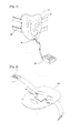
FIG. 2 is a perspective view illustrating a facial massage device according to an exemplary embodiment of the present invention; -
FIG. 3 is an exploded perspective view illustrating the facial massage device according to the exemplary embodiment of the present invention; -
FIG. 4 is a sectional view taken along the line A-A ofFIG. 2 ; -
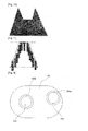
FIG. 5 is a perspective view illustrating a vibration module of the facial massage device according to the exemplary embodiment of the present invention; -
FIG. 6 is a side view of the vibration module ofFIG. 5 ; -
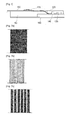
FIGS. 7A to 7E are views showing output pulses from a controller of the vibration module of the facial massage device according to the exemplary embodiment of the present invention; and -
FIG. 8 is a rear side view illustrating the vibration module of the facial massage device according to the exemplary embodiment of the present invention. - Hereinafter, a facial massage device according to an exemplary embodiment of the present invention will be described in detail with reference to the accompanying drawings.
-
FIG. 2 is a perspective view illustrating a facial massage device according to an exemplary embodiment of the present invention,FIG. 3 is an exploded perspective view illustrating the facial massage device according to the exemplary embodiment of the present invention,FIG. 4 is a sectional view taken along the line A-A ofFIG. 2 ,FIG. 5 is a perspective view illustrating a vibration module of the facial massage device according to the exemplary embodiment of the present invention,FIGS. 7A to 7E are views showing output pulses from a controller of the vibration module of the facial massage device according to the exemplary embodiment of the present invention, andFIG. 8 is a rear side view illustrating the vibration module of the facial massage device according to the exemplary embodiment of the present invention. - As illustrated in
FIG. 2 , a facial massage device according to an exemplary embodiment of the present invention includes amask 200 and a plurality ofvibration modules 100 and configurations and operations of elements thereof will be described with reference toFIG. 2 . - The
mask 200 forms an accommodation space for thevibration modules 100 such that thevibration modules 100 are accommodated in the accommodation space of themask 200 and provide massage function to human face during vibration. At least onevibration module 100 may be provided and has own power supply to be driven independently. Due to this, the facial massage device drives thevibration modules 100 of themask 200 without an external power supply to provide various massage functions and massages a specific portion of human face or the other portion excluding the specific portion. - The facial massage device according to the exemplary embodiment of the present invention will be described with reference to
FIGS. 2 to 8 . - Referring to
FIGS. 2 to 4 , the facial massage device includes afirst mask 210, asecond mask 220, andvibration modules 100. The facial massage device may further include a wearingunit 300. - The
first mask 210 and thesecond mask 220 are fixed by the circumstance of the mask to form the accommodation space therein. At least one of thefirst mask 210 and thesecond mask 220 has insertion holes allowing thevibration modules 100 to be inserted or withdrawn therethrough orinsertion holes 210a through whichinsulators 180 of the vibration modules are withdrawn out. In this embodiment, thefirst mask 210 has theinsertion holes 210a for withdraw of theinsulators 180. - The
vibration modules 100 will be described withFIGS. 5 to 8 . Referring toFIGS. 5 and6 , each of thevibration modules 100 includes a printedcircuit board 110, avibrator 120, adrive 130, acontroller 140, abattery 150, a supportingplate 160, apower connecting member 170, and aninsulator 180. - The printed
circuit board 110 is configured such that thevibrator 120 is installed on a side thereof and thedrive 130 and thecontroller 140 are mounted thereon. Thus, the printedcircuit board 110 has a circuit pattern for electrical connection between thebattery 150, thedrive 120, and thecontroller 130. The printedcircuit board 110 may be a flexible printed circuit board (FPCB) for the purpose of allowing thevibration modules 100 being bent along contours of a user's face and closed attached thereto. - The
vibrator 120 is installed on the printedcircuit board 110 and vibrates by receiving an electric power by thedrive 130. Thevibrator 120 is a device stimulating user's skin with vibration therefrom. That is, thevibrator 120 is not only a device of thevibration module 100 directly performing facial massage but also a device transmitting power the facial massage to thewhole vibration module 100. Thevibrator 120 may be inserted intovibrator holes 160a formed in the printedcircuit board 110 and the supportingplate 160. - This is because of reduction of overall thickness of the vibration module of the
facial massage device 100, and in other words, the overall thickness of thevibration module 100, when thevibrator 120 is installed on a side of the printedcircuit board 110, becomes sum of the thickness of thevibrator 120 and the thicknesses of the printedcircuit board 110 and the supportingplate 160. Thus, thevibrator holes 160a are formed in the printedcircuit board 110 and the supportingplate 160 and thevibrator 120 is inserted into thevibrator holes 160a and the thicknesses of the printedcircuit board 110 and the supportingplate 160 is subtracted from the overall thickness of thevibration module 100 so that the overall thickness of thevibration module 100 can be reduced. - The
drive 130 is mounted on the printedcircuit board 110 and received electric power from thebattery 150 to supply the received electric power to thevibrator 120. Thedrive 130 may be any one of a vibration motor, a solenoid, a piezo device, and a linear vibrator. - The
controller 140 is mounted on the printedcircuit board 110 and controls thedrive 130 to adjust vibration of thevibrator 120. Thecontroller 140 controls thedrive 130 in pulse width modulation (PWM). That is, thecontroller 140 operates thedrive 130 in various modes through the PWM, while outputting at least two different pulses wherein the different output pulses are sequentially output or only a preset one type pulse is continuously output. Thevibrator 120 may vibrate to provide various massage functions such as appeasing, rubbing, picking, pressing, knocking, etc., according to the various output pulses and the operating conditions of thedrive 130. - As illustrated in
FIG. 7, FIGS. 7A to 7I are views showing massage operations of the vibrator which vibrates in different types according to output pulses output from thecontroller 140 to thedrive 130. That is, the colored portions in the drawings are portions to which vibration of the vibrator is transmitted and the other portion is portion where the vibrator is stopped or not attached. -
FIG. 7A shows a case where relatively strong vibration continues same intensity for a preset time,FIG. 7B shows relatively strong vibration of same intensity repeated every preset short time interval, andFIG. 7C shows relatively strong vibration of same intensity repeated for a preset time every short time interval. Moreover,FIG. 7D shows visually weak vibration being gradually stronger for a preset time after starting andFIG. 7E shows strong vibration being gradually weakening for a preset time after starting contrary to the case ofFIG. 7D. FIG. 7F shows early weak vibration is gradually stronger to the peak and is gradually weakened again. The description for the rest drawings,FIGS. 7G to 7I is omitted. - Return to
FIGS. 5 and6 , thebattery 150 is installed on the supportingplate 160 and supplies electric power to thedrive 130 and thecontroller 140 through thepower connecting member 170. Thebattery 150 may be inserted into abattery hole 160b formed in the supportingplate 160 so as to reduce the overall thickness of thevibration module 100 and its description is omitted because this is substantially identical to the insertion of thevibrator 120 into thevibrator holes 160a. - The supporting
plate 160 is provided to connect the printedcircuit board 110 to thebattery 150 integrally. The supportingplate 160 may be made of a flexible material such that flexibility of thevibration module 100 can be guaranteed. Moreover, the supportingplate 160 may be configured such that thebattery 150 and thevibrator 120 are mounted at the ends in the major axis on an oval side of the supportingplate 160, respectively. Thus, devices are not mounted at the middle portion of the major axis and due to this the supportingplate 160 can exhibit elasticity and higher flexibility. - The
power connecting member 170 electrically connects the power terminals (not shown) of thebattery 150 to the power terminals (not shown) of thedrive 130 on the printedcircuit board 110. In other words, thedrive 130 receives electric power from thebattery 150 through thepower connecting member 170. Moreover, the power terminals of the printedcircuit board 110 may supply electric power to thecontroller 140 and in this case the printedcircuit board 110 has circuit patterns connecting the power terminals to thedrive 130 and thecontroller 140 in parallel. - The
insulator 180 is attached to a contact area between the power terminals of thebattery 150 and thepower connecting member 170. That is, theinsulator 180 is attached to thebattery 150 to interrupt the electrical connection between the power terminals of thebattery 150 and thepower connecting member 170 and the electrical connection between the power terminals of thebattery 150 and theinsulator 180 is made when theinsulator 180 is separated from thebattery 150. Theinsulator 180 is detachably attached to thebattery 150 and controls the electrical connection between the power terminals of thebattery 150 and thepower connection member 170 through the attachment and detachment of theinsulator 180 to control the electric power to be supplied from thebattery 150 to thedrive 130 or not. - In other words, the
insulator 180 can switch the electrical connection between the power terminals of thebattery 150 and thepower connecting member 170 and in this case thevibration module 100 can spend the electric power of thebattery 150 only by the switching function of theinsulator 180 even without a separated switch. That is, omission of the switch allows reduction of volume of thevibration module 100 and the electric power of thebattery 150 may be spent only when thevibrator 120 is operated. - Although in this exemplary embodiment a thin sheet of the
insulator 180 is detachably attached to thebattery 150 to screen the power terminals, the present invention is not limited thereto but theinsulator 180 may be attached to and detached from power terminal regions of thebattery 150 and may be modified under the conditions of applying electric power between the power terminals of thebattery 150 and thepower connecting member 170. -
FIG. 8 is a rear side view of the vibration module of the facial massage device according to the exemplary embodiment of the present invention in which thebattery 150 and thevibrator 120 are inserted into thebattery hole 160b and the vibrator holes 160a that are formed in the printedcircuit board 110 and the supportingplate 160 and are fixed thereto. A buffering pad (not shown) may be attached to the rear side of the vibration module 100 (the rear side of the supporting plate) and may prevent direct contact between thevibrator 120 and human skin. InFIG. 8 , the buffering pad is omitted for the purpose of showing thebattery hole 160b and the vibrator holes 160a and ones of sides of thebattery 150 and thevibrator 120 which are inserted thereinto. Moreover, the buffering pad may be made in various types such as nonwoven fabric or a sheet containing liquid material. - Referring to
FIGS. 2 to 4 again, the wearingunit 300 puts the mask on human head and is like a hair band in this embodiment, but the present invention is not limited thereto. The wearingunit 300 consists of a pair of bands one ends of which are fixed to lateral sides of themask 200 and the other ends of which are provided withVelcro tapes 310 for connecting each other. Lengths of theVelcro tapes 310 are relatively long such that length of the wearingunit 300 can be adjusted by contact portions between theVelcro tapes 310. - As described with reference to
FIGS. 2 to 8 , the facial massage device of the present invention can exhibit massage functions by driving a plurality ofvibration modules 100 of themask 200 which are independently driven by own power supply even without a separated external power supply. Moreover, since a plurality ofvibration modules 100 massage a specific portion of human face or the other portion excluding the specific portion by user's choice, the facial massage device of the present invention can provide proper massage functions according to face skin conditions and personal tendency. - In addition, since the drives of the
vibration modules 100 are controlled in pulse width modulation (PWM) to drive the vibrators receiving power from the drives to be operated in various vibration patterns, the facial massage device of the present invention can provide various massage function such as appeasing, rubbing, picking, pressing, and knocking by controlling vibration patterns of the vibration modules. - While this invention has been particularly shown and described with reference to preferred embodiments thereof, these embodiments are provided so that this disclosure will be thorough and complete, and will fully convey the concept of the invention to those skilled in the art. It will be understood by those skilled in the art that various changes in form and details may be made therein without departing from the spirit and scope of the invention as defined by the appended claims.
-
- 100: a vibration module for skin massage 110: a printed circuit board
- 120: a vibrator 130: a drive
- 140: a controller 150: a battery
- 160: a supporting
plate 160a: a vibrator hole - 160b: a battery hole 170: a power connecting member
- 180: an insulator 200: a mask
- 210: a
first mask 210a: an insertion hole - 220: a second mask 300: a wearing unit
- 310: a Velcro tape
Claims (5)
- A facial massage device, comprising:a mask having an accommodation space therein; andat least one vibration module accommodate in the accommodation space of the mask and having own power supply for allowing an independent operation.
- The facial massage device of claim 1, wherein the mask comprises a first mask and a second mask circumstances of which are fixed to each other to form the accommodation space therein, and at least one of the first mask and the second mask has at least one of insertion holes for insertion and withdraw of the vibration module.
- The facial massage device of claim 1, wherein the vibration module comprises:a printed circuit board;a vibrator installed on the printed circuit board;a drive mounted on the printed circuit board to provide vibration force of the vibrator when electric power is supplied;a battery supplying the electric power to the drive;a supporting plate integrally connecting the printed circuit board to the battery;a power connecting member electrically connecting power terminals of the battery to power terminals of the drive on the printed circuit board; andan insulator attached to a contact region between the power terminals of the battery and the power connecting member and allowing contact between the power terminals of the battery and the power connecting member when the vibration module is separated from the battery.
- The facial massage device of claim 3, wherein the vibration module further comprises a controller controlling the drive to control the vibration state of the vibrator, and
the controller controls the drive in pulse width modulation (PWM) such that at least two different pulses are output to the drive while the at least two different pulses are sequentially output according to a preset reference or only one pulse is continuously output. - The facial massage device of claim 1, further comprising a wearing unit for allowing the mask to be put on human head.
Applications Claiming Priority (2)
| Application Number | Priority Date | Filing Date | Title |
|---|---|---|---|
| KR2020110006379U KR200466320Y1 (en) | 2011-07-13 | 2011-07-13 | Massage device for face |
| PCT/KR2012/005555 WO2013009119A2 (en) | 2011-07-13 | 2012-07-13 | Face massaging device |
Publications (3)
| Publication Number | Publication Date |
|---|---|
| EP2719367A2 true EP2719367A2 (en) | 2014-04-16 |
| EP2719367A4 EP2719367A4 (en) | 2015-03-25 |
| EP2719367B1 EP2719367B1 (en) | 2017-09-06 |
Family
ID=47506731
Family Applications (1)
| Application Number | Title | Priority Date | Filing Date |
|---|---|---|---|
| EP12811402.2A Not-in-force EP2719367B1 (en) | 2011-07-13 | 2012-07-13 | Face massaging device |
Country Status (8)
| Country | Link |
|---|---|
| US (2) | US9744096B2 (en) |
| EP (1) | EP2719367B1 (en) |
| JP (1) | JP5832648B2 (en) |
| KR (1) | KR200466320Y1 (en) |
| CN (1) | CN203763473U (en) |
| HK (1) | HK1195196A2 (en) |
| TW (1) | TWM444837U (en) |
| WO (1) | WO2013009119A2 (en) |
Families Citing this family (24)
| Publication number | Priority date | Publication date | Assignee | Title |
|---|---|---|---|---|
| KR101348554B1 (en) * | 2012-09-26 | 2014-01-09 | 김종택 | Beauty massage apparatus |
| NL1040380C2 (en) | 2013-09-07 | 2015-03-10 | Anthonius Fredericus Maria Bende | Face masks and software/application for activating no production in sinuses. |
| JP6425124B2 (en) * | 2014-01-31 | 2018-11-21 | パナソニックIpマネジメント株式会社 | Massage device |
| JP2015186568A (en) * | 2014-03-13 | 2015-10-29 | パナソニックIpマネジメント株式会社 | massage device and massage method |
| JP6358532B2 (en) * | 2014-03-13 | 2018-07-18 | パナソニックIpマネジメント株式会社 | Massage measuring device and massage measuring method |
| TW201544093A (en) * | 2014-05-28 | 2015-12-01 | Chi-Mou Chao | A vibrating massage apparatus and a bluetooth headset |
| KR101537487B1 (en) * | 2014-11-03 | 2015-07-22 | 민치훈 | A Mask Vibration cleansing Apparatus |
| TWI569742B (en) * | 2015-10-08 | 2017-02-11 | 楊志鴻 | Piezoelectric stimulation element, piezoelectric stimulator and insole having piezoelectric stimulation element |
| KR101713579B1 (en) * | 2015-12-22 | 2017-03-09 | (주)아모레퍼시픽 | Massage apparatus to be skin lifting |
| US20170181923A1 (en) * | 2015-12-29 | 2017-06-29 | HCT Group Holdings Limited | Facial massaging mask |
| US11031117B2 (en) * | 2016-04-18 | 2021-06-08 | Vmas Solutions, Inc. | Systems and methods for reducing stress |
| US20170296429A1 (en) * | 2016-04-18 | 2017-10-19 | VMAS Solutions LLC | System and method for reducing chronic and acute stress |
| CN107231186A (en) * | 2017-07-14 | 2017-10-03 | 北斗民用战略新兴产业(重庆)研究院有限公司 | A kind of carry-on communication apparatus and its manufacture craft |
| US20190053949A1 (en) * | 2017-08-16 | 2019-02-21 | Sylvia Morris | Eye Mask and Method of Using Same |
| CN108144193A (en) * | 2017-12-28 | 2018-06-12 | 武汉爱迪斯工业设计有限公司 | Portable red blue light beauty instrument, cosmetic system and its beauty method |
| KR101861509B1 (en) * | 2018-02-28 | 2018-05-28 | (주)피앤씨산업 | Electronic mask pack set |
| KR102128022B1 (en) | 2018-10-12 | 2020-06-30 | 주식회사 안온 | Complex type head beauty device |
| KR102025131B1 (en) * | 2019-01-17 | 2019-09-25 | 김유곤 | Micro current and vibration mask |
| KR102212087B1 (en) | 2019-02-22 | 2021-02-05 | 장현아 | Head beauty device sets |
| KR20200132182A (en) * | 2019-05-16 | 2020-11-25 | 주식회사 엘지생활건강 | A skin care device |
| KR102441833B1 (en) * | 2019-06-14 | 2022-09-13 | 주식회사 아모센스 | Mask for Skincare |
| CN113384816A (en) * | 2020-03-13 | 2021-09-14 | 邵玉忠 | Touch simulation device, masturbation device, face massager and face massage system |
| CN111840039B (en) * | 2020-07-05 | 2022-07-05 | 深圳市赢运顾问咨询有限公司 | Automated face-thinning treatment system using parameter detection |
| CN113489322A (en) * | 2021-07-30 | 2021-10-08 | 阿木(深圳)新科技有限公司 | Power supply circuit, power supply device and micro-current mask |
Family Cites Families (52)
| Publication number | Priority date | Publication date | Assignee | Title |
|---|---|---|---|---|
| US2755803A (en) * | 1955-01-05 | 1956-07-24 | Dorsey Stella | Eyeshield |
| US3557781A (en) * | 1969-01-21 | 1971-01-26 | Kavibro Ind Inc | Vibratory facial mask |
| US4052981A (en) * | 1976-08-03 | 1977-10-11 | Bachmann Robert J | Massaging method and apparatus |
| US5099829A (en) * | 1990-04-25 | 1992-03-31 | Wu An Chuan | Massage device good for eyes |
| US5072724A (en) * | 1990-11-23 | 1991-12-17 | Joseph Marcus | Vibrational liquid-wave stimulating therapy mask apparatus for facial health and beauty care |
| JP2858715B2 (en) * | 1992-07-23 | 1999-02-17 | 富士写真フイルム株式会社 | Film unit with lens |
| US5302806A (en) * | 1992-12-08 | 1994-04-12 | Thermo-Cool Products Inc. | Heated vest with pouches for accommodating inserted heating packets |
| US5344437A (en) * | 1993-05-10 | 1994-09-06 | Sub I.P., Inc. | Massaging therapeutic pillow with removable ice pack |
| US5583478A (en) * | 1995-03-01 | 1996-12-10 | Renzi; Ronald | Virtual environment tactile system |
| JPH11213974A (en) * | 1998-01-22 | 1999-08-06 | Sharp Corp | Battery insulating device |
| US6093164A (en) * | 1998-07-17 | 2000-07-25 | William M. Davis | Vibratory sleeve and method for the treatment of repetitive trauma syndrome |
| KR100291011B1 (en) * | 1998-09-16 | 2001-06-01 | 전병헌 | Mask for cosmetic massage |
| US6554787B1 (en) * | 1999-08-30 | 2003-04-29 | Brand N. Griffin | Headband for treatment of headaches |
| KR200184898Y1 (en) * | 1999-12-29 | 2000-06-01 | 신석균 | Massage glass mask |
| US6537308B2 (en) * | 2000-04-14 | 2003-03-25 | Alma D. Burkhart | Cosmetic and therapeutic face mask |
| KR200219489Y1 (en) * | 2000-10-31 | 2001-04-02 | 이양희 | A massage type mask |
| KR200219490Y1 (en) * | 2000-10-31 | 2001-04-02 | 이양희 | A massage for vibration of skin |
| JP3089625U (en) * | 2002-04-26 | 2002-10-31 | 林建豐 | Safety condom |
| US7147610B2 (en) * | 2003-06-19 | 2006-12-12 | Tarek Maalouf | Multiple combination heat/massage devices |
| US6907883B2 (en) * | 2003-10-16 | 2005-06-21 | Jerome Lin | Electric condom ring |
| US20050234373A1 (en) * | 2004-04-20 | 2005-10-20 | Khalaf Naila K | Seat belt massager |
| CN2721086Y (en) * | 2004-08-03 | 2005-08-31 | 卓文水 | Auxiliary device for male sextual function |
| US20060178602A1 (en) * | 2005-02-09 | 2006-08-10 | Wen-Chang Teng | Vibratory penis ring |
| TWI290463B (en) * | 2005-03-04 | 2007-12-01 | Bing-Hung Lin | Structure of massager |
| WO2006097266A1 (en) * | 2005-03-16 | 2006-09-21 | Unilever Plc | A device for washing and creating massaging vibrations within a bar of soap |
| US7300409B2 (en) * | 2005-05-12 | 2007-11-27 | S.C. Johnson & Son, Inc. | Therapy patch |
| US7182739B2 (en) * | 2005-05-12 | 2007-02-27 | S.C. Johnson & Son, Inc. | Therapy patch |
| US20060287615A1 (en) * | 2005-06-15 | 2006-12-21 | Tsung-I Yu | Massaging mask |
| WO2007046081A2 (en) * | 2005-10-16 | 2007-04-26 | Eran Izhak Prizant | Bandage |
| US7815582B2 (en) * | 2006-02-01 | 2010-10-19 | Jimmyjane, Inc. | Networkable personal care device |
| US20070255187A1 (en) * | 2006-04-26 | 2007-11-01 | Branch Alan P | Vibrating therapy device |
| IL176025A0 (en) * | 2006-05-30 | 2007-08-19 | Nexense Ltd | Force or displacement sensor |
| GB0613455D0 (en) * | 2006-07-06 | 2006-08-16 | Lrc Products | Sexual stimulation device |
| US20080027363A1 (en) * | 2006-07-25 | 2008-01-31 | Sarah Louisa Brueckmann | Therapeutic vibrating unit |
| US20080139943A1 (en) * | 2006-12-07 | 2008-06-12 | Industrial Technology Research Institute | Ultrasonic wave device |
| US7766849B2 (en) * | 2007-02-27 | 2010-08-03 | Nanma Manufacturing Co., Ltd. | Disposable massage apparatus |
| US7871386B2 (en) * | 2007-03-16 | 2011-01-18 | Nanma Manufacturing Co., Ltd. | Miniature massage vibrator |
| US8840573B2 (en) * | 2007-08-28 | 2014-09-23 | Stryker Corporation | Apparatuses for and method of preventing decubitus ulcers |
| TW200908945A (en) * | 2007-08-31 | 2009-03-01 | Kuo Nao Co Ltd | Eyes cover capable of being adjusted according to the face shape |
| US20100249637A1 (en) * | 2008-05-08 | 2010-09-30 | Lotus Magnus, Llc | Systems, devices, and methods for treating restless leg syndrome and periodic limb movement disorder |
| KR100995427B1 (en) * | 2008-06-13 | 2010-11-18 | 원테크놀로지 주식회사 | Hair Growth Stimulation Laser Treatment Device |
| JP2012501175A (en) * | 2008-08-28 | 2012-01-19 | ネステク ソシエテ アノニム | Gene expression profiles associated with lean phenotypes and their use |
| US7630203B1 (en) * | 2008-09-17 | 2009-12-08 | Ardi Technology Corporation | IC card |
| EP2358266A4 (en) * | 2008-11-20 | 2012-10-03 | Bodymedia Inc | Method and apparatus for determining critical care parameters |
| US20100236130A1 (en) * | 2009-03-23 | 2010-09-23 | Basso Paul T | Simulated insect top water fishing lure |
| CN102548518A (en) * | 2009-10-08 | 2012-07-04 | 丘奇和德怀特有限公司 | Vibrating band |
| JP3156656U (en) * | 2009-10-16 | 2010-01-14 | 弓長 薫 | Vibration massage ship or affixed sheet and its product structure |
| US20110208279A1 (en) * | 2010-02-19 | 2011-08-25 | Daniel Allen Sanker | Method and therapeutic apparatus for normalizing function of sinus cilia using heat |
| GB201007153D0 (en) * | 2010-04-29 | 2010-06-09 | Auris Medical Ltd | Desensitising apparatus |
| US20120023785A1 (en) * | 2010-06-05 | 2012-02-02 | Nathaniel K. Barnes | Wireless remote controlled massaging footwear system |
| US20120022411A1 (en) * | 2010-07-23 | 2012-01-26 | Top-Bound Enterprise Co. Ltd. | Skin-cover Structure |
| US20120116273A1 (en) * | 2010-11-08 | 2012-05-10 | Nanma Manufacturing Co., Ltd. | Finger-mounted massage apparatus |
-
2011
- 2011-07-13 KR KR2020110006379U patent/KR200466320Y1/en active IP Right Grant
-
2012
- 2012-07-13 JP JP2014520130A patent/JP5832648B2/en not_active Expired - Fee Related
- 2012-07-13 TW TW101213565U patent/TWM444837U/en not_active IP Right Cessation
- 2012-07-13 EP EP12811402.2A patent/EP2719367B1/en not_active Not-in-force
- 2012-07-13 HK HK14104123.6A patent/HK1195196A2/en not_active IP Right Cessation
- 2012-07-13 US US14/232,471 patent/US9744096B2/en not_active Expired - Fee Related
- 2012-07-13 WO PCT/KR2012/005555 patent/WO2013009119A2/en active Application Filing
- 2012-07-13 US US14/232,545 patent/US20140163438A1/en not_active Abandoned
- 2012-07-13 CN CN201290000652.XU patent/CN203763473U/en not_active Expired - Fee Related
Non-Patent Citations (2)
| Title |
|---|
| No further relevant documents disclosed * |
| See also references of WO2013009119A2 * |
Also Published As
| Publication number | Publication date |
|---|---|
| EP2719367A4 (en) | 2015-03-25 |
| JP2014530640A (en) | 2014-11-20 |
| CN203763473U (en) | 2014-08-13 |
| JP5832648B2 (en) | 2015-12-16 |
| US9744096B2 (en) | 2017-08-29 |
| HK1195196A2 (en) | 2014-10-31 |
| US20140163438A1 (en) | 2014-06-12 |
| US20140142477A1 (en) | 2014-05-22 |
| KR200466320Y1 (en) | 2013-04-12 |
| WO2013009119A2 (en) | 2013-01-17 |
| WO2013009119A3 (en) | 2013-04-11 |
| KR20130000537U (en) | 2013-01-23 |
| TWM444837U (en) | 2013-01-11 |
| EP2719367B1 (en) | 2017-09-06 |
Similar Documents
| Publication | Publication Date | Title |
|---|---|---|
| EP2719367B1 (en) | Face massaging device | |
| EP2730311B1 (en) | Facial massager | |
| JP4852198B2 (en) | Relaxation equipment | |
| WO2021014784A1 (en) | Cosmetic mask for eyes | |
| KR20130068331A (en) | Beauty care device controlled by mobile phone | |
| EP2719366B1 (en) | Vibration module for massaging skin | |
| KR20080043709A (en) | Treatment apparatus using a low frequency | |
| KR200185058Y1 (en) | Face massager | |
| EP2730312B1 (en) | Electric module for stimulating skin | |
| KR200327533Y1 (en) | Massagist of the face | |
| JP2722357B2 (en) | Biological stimulator | |
| CN103764090B (en) | The vibration module of skin massaging | |
| JP7148195B1 (en) | stimulation system | |
| KR20040103601A (en) | Massagist of the face | |
| JP2002000684A (en) | Ultrasonic beauty device |
Legal Events
| Date | Code | Title | Description |
|---|---|---|---|
| PUAI | Public reference made under article 153(3) epc to a published international application that has entered the european phase |
Free format text: ORIGINAL CODE: 0009012 |
|
| 17P | Request for examination filed |
Effective date: 20140113 |
|
| AK | Designated contracting states |
Kind code of ref document: A2 Designated state(s): AL AT BE BG CH CY CZ DE DK EE ES FI FR GB GR HR HU IE IS IT LI LT LU LV MC MK MT NL NO PL PT RO RS SE SI SK SM TR |
|
| DAX | Request for extension of the european patent (deleted) | ||
| A4 | Supplementary search report drawn up and despatched |
Effective date: 20150220 |
|
| RIC1 | Information provided on ipc code assigned before grant |
Ipc: A61H 23/00 20060101ALI20150216BHEP Ipc: A61H 39/04 20060101ALI20150216BHEP Ipc: A61H 7/00 20060101ALI20150216BHEP Ipc: A61H 23/02 20060101AFI20150216BHEP |
|
| 17Q | First examination report despatched |
Effective date: 20160308 |
|
| GRAP | Despatch of communication of intention to grant a patent |
Free format text: ORIGINAL CODE: EPIDOSNIGR1 |
|
| INTG | Intention to grant announced |
Effective date: 20170405 |
|
| GRAS | Grant fee paid |
Free format text: ORIGINAL CODE: EPIDOSNIGR3 |
|
| GRAA | (expected) grant |
Free format text: ORIGINAL CODE: 0009210 |
|
| AK | Designated contracting states |
Kind code of ref document: B1 Designated state(s): AL AT BE BG CH CY CZ DE DK EE ES FI FR GB GR HR HU IE IS IT LI LT LU LV MC MK MT NL NO PL PT RO RS SE SI SK SM TR |
|
| REG | Reference to a national code |
Ref country code: GB Ref legal event code: FG4D |
|
| REG | Reference to a national code |
Ref country code: CH Ref legal event code: EP Ref country code: AT Ref legal event code: REF Ref document number: 925080 Country of ref document: AT Kind code of ref document: T Effective date: 20170915 |
|
| REG | Reference to a national code |
Ref country code: IE Ref legal event code: FG4D |
|
| REG | Reference to a national code |
Ref country code: DE Ref legal event code: R096 Ref document number: 602012037065 Country of ref document: DE |
|
| REG | Reference to a national code |
Ref country code: NL Ref legal event code: MP Effective date: 20170906 |
|
| REG | Reference to a national code |
Ref country code: LT Ref legal event code: MG4D |
|
| PG25 | Lapsed in a contracting state [announced via postgrant information from national office to epo] |
Ref country code: SE Free format text: LAPSE BECAUSE OF FAILURE TO SUBMIT A TRANSLATION OF THE DESCRIPTION OR TO PAY THE FEE WITHIN THE PRESCRIBED TIME-LIMIT Effective date: 20170906 Ref country code: NO Free format text: LAPSE BECAUSE OF FAILURE TO SUBMIT A TRANSLATION OF THE DESCRIPTION OR TO PAY THE FEE WITHIN THE PRESCRIBED TIME-LIMIT Effective date: 20171206 Ref country code: FI Free format text: LAPSE BECAUSE OF FAILURE TO SUBMIT A TRANSLATION OF THE DESCRIPTION OR TO PAY THE FEE WITHIN THE PRESCRIBED TIME-LIMIT Effective date: 20170906 Ref country code: LT Free format text: LAPSE BECAUSE OF FAILURE TO SUBMIT A TRANSLATION OF THE DESCRIPTION OR TO PAY THE FEE WITHIN THE PRESCRIBED TIME-LIMIT Effective date: 20170906 Ref country code: HR Free format text: LAPSE BECAUSE OF FAILURE TO SUBMIT A TRANSLATION OF THE DESCRIPTION OR TO PAY THE FEE WITHIN THE PRESCRIBED TIME-LIMIT Effective date: 20170906 |
|
| REG | Reference to a national code |
Ref country code: AT Ref legal event code: MK05 Ref document number: 925080 Country of ref document: AT Kind code of ref document: T Effective date: 20170906 |
|
| PG25 | Lapsed in a contracting state [announced via postgrant information from national office to epo] |
Ref country code: RS Free format text: LAPSE BECAUSE OF FAILURE TO SUBMIT A TRANSLATION OF THE DESCRIPTION OR TO PAY THE FEE WITHIN THE PRESCRIBED TIME-LIMIT Effective date: 20170906 Ref country code: LV Free format text: LAPSE BECAUSE OF FAILURE TO SUBMIT A TRANSLATION OF THE DESCRIPTION OR TO PAY THE FEE WITHIN THE PRESCRIBED TIME-LIMIT Effective date: 20170906 Ref country code: GR Free format text: LAPSE BECAUSE OF FAILURE TO SUBMIT A TRANSLATION OF THE DESCRIPTION OR TO PAY THE FEE WITHIN THE PRESCRIBED TIME-LIMIT Effective date: 20171207 Ref country code: BG Free format text: LAPSE BECAUSE OF FAILURE TO SUBMIT A TRANSLATION OF THE DESCRIPTION OR TO PAY THE FEE WITHIN THE PRESCRIBED TIME-LIMIT Effective date: 20171206 Ref country code: ES Free format text: LAPSE BECAUSE OF FAILURE TO SUBMIT A TRANSLATION OF THE DESCRIPTION OR TO PAY THE FEE WITHIN THE PRESCRIBED TIME-LIMIT Effective date: 20170906 |
|
| PG25 | Lapsed in a contracting state [announced via postgrant information from national office to epo] |
Ref country code: NL Free format text: LAPSE BECAUSE OF FAILURE TO SUBMIT A TRANSLATION OF THE DESCRIPTION OR TO PAY THE FEE WITHIN THE PRESCRIBED TIME-LIMIT Effective date: 20170906 |
|
| PG25 | Lapsed in a contracting state [announced via postgrant information from national office to epo] |
Ref country code: CZ Free format text: LAPSE BECAUSE OF FAILURE TO SUBMIT A TRANSLATION OF THE DESCRIPTION OR TO PAY THE FEE WITHIN THE PRESCRIBED TIME-LIMIT Effective date: 20170906 Ref country code: RO Free format text: LAPSE BECAUSE OF FAILURE TO SUBMIT A TRANSLATION OF THE DESCRIPTION OR TO PAY THE FEE WITHIN THE PRESCRIBED TIME-LIMIT Effective date: 20170906 Ref country code: PL Free format text: LAPSE BECAUSE OF FAILURE TO SUBMIT A TRANSLATION OF THE DESCRIPTION OR TO PAY THE FEE WITHIN THE PRESCRIBED TIME-LIMIT Effective date: 20170906 |
|
| PG25 | Lapsed in a contracting state [announced via postgrant information from national office to epo] |
Ref country code: AT Free format text: LAPSE BECAUSE OF FAILURE TO SUBMIT A TRANSLATION OF THE DESCRIPTION OR TO PAY THE FEE WITHIN THE PRESCRIBED TIME-LIMIT Effective date: 20170906 Ref country code: SM Free format text: LAPSE BECAUSE OF FAILURE TO SUBMIT A TRANSLATION OF THE DESCRIPTION OR TO PAY THE FEE WITHIN THE PRESCRIBED TIME-LIMIT Effective date: 20170906 Ref country code: IS Free format text: LAPSE BECAUSE OF FAILURE TO SUBMIT A TRANSLATION OF THE DESCRIPTION OR TO PAY THE FEE WITHIN THE PRESCRIBED TIME-LIMIT Effective date: 20180106 Ref country code: IT Free format text: LAPSE BECAUSE OF FAILURE TO SUBMIT A TRANSLATION OF THE DESCRIPTION OR TO PAY THE FEE WITHIN THE PRESCRIBED TIME-LIMIT Effective date: 20170906 Ref country code: EE Free format text: LAPSE BECAUSE OF FAILURE TO SUBMIT A TRANSLATION OF THE DESCRIPTION OR TO PAY THE FEE WITHIN THE PRESCRIBED TIME-LIMIT Effective date: 20170906 Ref country code: SK Free format text: LAPSE BECAUSE OF FAILURE TO SUBMIT A TRANSLATION OF THE DESCRIPTION OR TO PAY THE FEE WITHIN THE PRESCRIBED TIME-LIMIT Effective date: 20170906 |
|
| REG | Reference to a national code |
Ref country code: DE Ref legal event code: R097 Ref document number: 602012037065 Country of ref document: DE |
|
| REG | Reference to a national code |
Ref country code: FR Ref legal event code: PLFP Year of fee payment: 7 |
|
| PLBE | No opposition filed within time limit |
Free format text: ORIGINAL CODE: 0009261 |
|
| STAA | Information on the status of an ep patent application or granted ep patent |
Free format text: STATUS: NO OPPOSITION FILED WITHIN TIME LIMIT |
|
| PG25 | Lapsed in a contracting state [announced via postgrant information from national office to epo] |
Ref country code: DK Free format text: LAPSE BECAUSE OF FAILURE TO SUBMIT A TRANSLATION OF THE DESCRIPTION OR TO PAY THE FEE WITHIN THE PRESCRIBED TIME-LIMIT Effective date: 20170906 |
|
| 26N | No opposition filed |
Effective date: 20180607 |
|
| PG25 | Lapsed in a contracting state [announced via postgrant information from national office to epo] |
Ref country code: SI Free format text: LAPSE BECAUSE OF FAILURE TO SUBMIT A TRANSLATION OF THE DESCRIPTION OR TO PAY THE FEE WITHIN THE PRESCRIBED TIME-LIMIT Effective date: 20170906 |
|
| REG | Reference to a national code |
Ref country code: DE Ref legal event code: R119 Ref document number: 602012037065 Country of ref document: DE |
|
| REG | Reference to a national code |
Ref country code: CH Ref legal event code: PL |
|
| GBPC | Gb: european patent ceased through non-payment of renewal fee |
Effective date: 20180713 |
|
| PG25 | Lapsed in a contracting state [announced via postgrant information from national office to epo] |
Ref country code: LU Free format text: LAPSE BECAUSE OF NON-PAYMENT OF DUE FEES Effective date: 20180713 Ref country code: MC Free format text: LAPSE BECAUSE OF FAILURE TO SUBMIT A TRANSLATION OF THE DESCRIPTION OR TO PAY THE FEE WITHIN THE PRESCRIBED TIME-LIMIT Effective date: 20170906 |
|
| REG | Reference to a national code |
Ref country code: BE Ref legal event code: MM Effective date: 20180731 |
|
| REG | Reference to a national code |
Ref country code: IE Ref legal event code: MM4A |
|
| PG25 | Lapsed in a contracting state [announced via postgrant information from national office to epo] |
Ref country code: CH Free format text: LAPSE BECAUSE OF NON-PAYMENT OF DUE FEES Effective date: 20180731 Ref country code: GB Free format text: LAPSE BECAUSE OF NON-PAYMENT OF DUE FEES Effective date: 20180713 Ref country code: LI Free format text: LAPSE BECAUSE OF NON-PAYMENT OF DUE FEES Effective date: 20180731 Ref country code: IE Free format text: LAPSE BECAUSE OF NON-PAYMENT OF DUE FEES Effective date: 20180713 Ref country code: DE Free format text: LAPSE BECAUSE OF NON-PAYMENT OF DUE FEES Effective date: 20190201 |
|
| PG25 | Lapsed in a contracting state [announced via postgrant information from national office to epo] |
Ref country code: BE Free format text: LAPSE BECAUSE OF NON-PAYMENT OF DUE FEES Effective date: 20180731 |
|
| PGFP | Annual fee paid to national office [announced via postgrant information from national office to epo] |
Ref country code: FR Payment date: 20190624 Year of fee payment: 8 |
|
| PG25 | Lapsed in a contracting state [announced via postgrant information from national office to epo] |
Ref country code: MT Free format text: LAPSE BECAUSE OF NON-PAYMENT OF DUE FEES Effective date: 20180713 |
|
| PG25 | Lapsed in a contracting state [announced via postgrant information from national office to epo] |
Ref country code: TR Free format text: LAPSE BECAUSE OF FAILURE TO SUBMIT A TRANSLATION OF THE DESCRIPTION OR TO PAY THE FEE WITHIN THE PRESCRIBED TIME-LIMIT Effective date: 20170906 |
|
| PG25 | Lapsed in a contracting state [announced via postgrant information from national office to epo] |
Ref country code: PT Free format text: LAPSE BECAUSE OF FAILURE TO SUBMIT A TRANSLATION OF THE DESCRIPTION OR TO PAY THE FEE WITHIN THE PRESCRIBED TIME-LIMIT Effective date: 20170906 Ref country code: HU Free format text: LAPSE BECAUSE OF FAILURE TO SUBMIT A TRANSLATION OF THE DESCRIPTION OR TO PAY THE FEE WITHIN THE PRESCRIBED TIME-LIMIT; INVALID AB INITIO Effective date: 20120713 |
|
| PG25 | Lapsed in a contracting state [announced via postgrant information from national office to epo] |
Ref country code: CY Free format text: LAPSE BECAUSE OF FAILURE TO SUBMIT A TRANSLATION OF THE DESCRIPTION OR TO PAY THE FEE WITHIN THE PRESCRIBED TIME-LIMIT Effective date: 20170906 Ref country code: MK Free format text: LAPSE BECAUSE OF NON-PAYMENT OF DUE FEES Effective date: 20170906 |
|
| PG25 | Lapsed in a contracting state [announced via postgrant information from national office to epo] |
Ref country code: AL Free format text: LAPSE BECAUSE OF FAILURE TO SUBMIT A TRANSLATION OF THE DESCRIPTION OR TO PAY THE FEE WITHIN THE PRESCRIBED TIME-LIMIT Effective date: 20170906 |
|
| PG25 | Lapsed in a contracting state [announced via postgrant information from national office to epo] |
Ref country code: FR Free format text: LAPSE BECAUSE OF NON-PAYMENT OF DUE FEES Effective date: 20200731 |