EP2718543B1 - Methods and apparatus for determining downhole parameters - Google Patents
Methods and apparatus for determining downhole parameters Download PDFInfo
- Publication number
- EP2718543B1 EP2718543B1 EP12800169.0A EP12800169A EP2718543B1 EP 2718543 B1 EP2718543 B1 EP 2718543B1 EP 12800169 A EP12800169 A EP 12800169A EP 2718543 B1 EP2718543 B1 EP 2718543B1
- Authority
- EP
- European Patent Office
- Prior art keywords
- fluid
- well
- sensor
- heater
- depth
- Prior art date
- Legal status (The legal status is an assumption and is not a legal conclusion. Google has not performed a legal analysis and makes no representation as to the accuracy of the status listed.)
- Active
Links
- 238000000034 method Methods 0.000 title claims description 65
- 239000012530 fluid Substances 0.000 claims description 158
- 238000010438 heat treatment Methods 0.000 claims description 8
- 238000005259 measurement Methods 0.000 description 47
- 238000011144 upstream manufacturing Methods 0.000 description 25
- 238000002347 injection Methods 0.000 description 23
- 239000007924 injection Substances 0.000 description 23
- 238000004891 communication Methods 0.000 description 21
- 239000013307 optical fiber Substances 0.000 description 20
- 230000006870 function Effects 0.000 description 10
- 238000001514 detection method Methods 0.000 description 7
- 229910052751 metal Inorganic materials 0.000 description 7
- 239000002184 metal Substances 0.000 description 7
- 238000004519 manufacturing process Methods 0.000 description 6
- IJGRMHOSHXDMSA-UHFFFAOYSA-N Atomic nitrogen Chemical compound N#N IJGRMHOSHXDMSA-UHFFFAOYSA-N 0.000 description 4
- 230000015572 biosynthetic process Effects 0.000 description 4
- 239000000835 fiber Substances 0.000 description 4
- XLYOFNOQVPJJNP-UHFFFAOYSA-N water Substances O XLYOFNOQVPJJNP-UHFFFAOYSA-N 0.000 description 4
- 239000004593 Epoxy Substances 0.000 description 3
- XQCFHQBGMWUEMY-ZPUQHVIOSA-N Nitrovin Chemical compound C=1C=C([N+]([O-])=O)OC=1\C=C\C(=NNC(=N)N)\C=C\C1=CC=C([N+]([O-])=O)O1 XQCFHQBGMWUEMY-ZPUQHVIOSA-N 0.000 description 3
- 239000002253 acid Substances 0.000 description 3
- 239000000853 adhesive Substances 0.000 description 3
- 230000001070 adhesive effect Effects 0.000 description 3
- 230000008859 change Effects 0.000 description 3
- 230000001276 controlling effect Effects 0.000 description 3
- 239000000463 material Substances 0.000 description 3
- 229910052757 nitrogen Inorganic materials 0.000 description 3
- 238000012545 processing Methods 0.000 description 3
- 230000004044 response Effects 0.000 description 3
- 239000000758 substrate Substances 0.000 description 3
- 238000003466 welding Methods 0.000 description 3
- 238000012935 Averaging Methods 0.000 description 2
- KDLHZDBZIXYQEI-UHFFFAOYSA-N Palladium Chemical compound [Pd] KDLHZDBZIXYQEI-UHFFFAOYSA-N 0.000 description 2
- 239000000919 ceramic Substances 0.000 description 2
- 230000009977 dual effect Effects 0.000 description 2
- 238000001595 flow curve Methods 0.000 description 2
- -1 for example Substances 0.000 description 2
- 239000007789 gas Substances 0.000 description 2
- 229930195733 hydrocarbon Natural products 0.000 description 2
- 150000002430 hydrocarbons Chemical class 0.000 description 2
- 229910052739 hydrogen Inorganic materials 0.000 description 2
- 239000001257 hydrogen Substances 0.000 description 2
- 238000003384 imaging method Methods 0.000 description 2
- 239000011261 inert gas Substances 0.000 description 2
- 238000000691 measurement method Methods 0.000 description 2
- 239000007769 metal material Substances 0.000 description 2
- 239000000203 mixture Substances 0.000 description 2
- 238000012986 modification Methods 0.000 description 2
- 230000004048 modification Effects 0.000 description 2
- 238000012544 monitoring process Methods 0.000 description 2
- BASFCYQUMIYNBI-UHFFFAOYSA-N platinum Chemical compound [Pt] BASFCYQUMIYNBI-UHFFFAOYSA-N 0.000 description 2
- 229910052709 silver Inorganic materials 0.000 description 2
- 239000004332 silver Substances 0.000 description 2
- 239000010409 thin film Substances 0.000 description 2
- UFHFLCQGNIYNRP-UHFFFAOYSA-N Hydrogen Chemical compound [H][H] UFHFLCQGNIYNRP-UHFFFAOYSA-N 0.000 description 1
- 244000261422 Lysimachia clethroides Species 0.000 description 1
- 239000004696 Poly ether ether ketone Substances 0.000 description 1
- BQCADISMDOOEFD-UHFFFAOYSA-N Silver Chemical compound [Ag] BQCADISMDOOEFD-UHFFFAOYSA-N 0.000 description 1
- 150000007513 acids Chemical class 0.000 description 1
- 230000004075 alteration Effects 0.000 description 1
- 238000004458 analytical method Methods 0.000 description 1
- 238000003491 array Methods 0.000 description 1
- 230000000712 assembly Effects 0.000 description 1
- 238000000429 assembly Methods 0.000 description 1
- 230000006399 behavior Effects 0.000 description 1
- 238000005452 bending Methods 0.000 description 1
- JUPQTSLXMOCDHR-UHFFFAOYSA-N benzene-1,4-diol;bis(4-fluorophenyl)methanone Chemical compound OC1=CC=C(O)C=C1.C1=CC(F)=CC=C1C(=O)C1=CC=C(F)C=C1 JUPQTSLXMOCDHR-UHFFFAOYSA-N 0.000 description 1
- 230000002457 bidirectional effect Effects 0.000 description 1
- 238000005219 brazing Methods 0.000 description 1
- 239000003795 chemical substances by application Substances 0.000 description 1
- 230000000295 complement effect Effects 0.000 description 1
- 230000006835 compression Effects 0.000 description 1
- 238000007906 compression Methods 0.000 description 1
- 230000008878 coupling Effects 0.000 description 1
- 238000010168 coupling process Methods 0.000 description 1
- 238000005859 coupling reaction Methods 0.000 description 1
- 230000005611 electricity Effects 0.000 description 1
- 239000010408 film Substances 0.000 description 1
- 238000010304 firing Methods 0.000 description 1
- 230000004907 flux Effects 0.000 description 1
- 230000005251 gamma ray Effects 0.000 description 1
- 230000017525 heat dissipation Effects 0.000 description 1
- 230000020169 heat generation Effects 0.000 description 1
- 229910001026 inconel Inorganic materials 0.000 description 1
- 238000002955 isolation Methods 0.000 description 1
- 230000007246 mechanism Effects 0.000 description 1
- 238000000465 moulding Methods 0.000 description 1
- 238000010606 normalization Methods 0.000 description 1
- 230000003287 optical effect Effects 0.000 description 1
- 238000004806 packaging method and process Methods 0.000 description 1
- 229910052763 palladium Inorganic materials 0.000 description 1
- 229910052698 phosphorus Inorganic materials 0.000 description 1
- 238000000053 physical method Methods 0.000 description 1
- 229910052697 platinum Inorganic materials 0.000 description 1
- 229920000647 polyepoxide Polymers 0.000 description 1
- 229920002530 polyetherether ketone Polymers 0.000 description 1
- 230000001681 protective effect Effects 0.000 description 1
- 230000001105 regulatory effect Effects 0.000 description 1
- 238000005070 sampling Methods 0.000 description 1
- 239000004576 sand Substances 0.000 description 1
- 229910052594 sapphire Inorganic materials 0.000 description 1
- 239000010980 sapphire Substances 0.000 description 1
- 229910001220 stainless steel Inorganic materials 0.000 description 1
- 239000010935 stainless steel Substances 0.000 description 1
- 230000000638 stimulation Effects 0.000 description 1
- 229910052715 tantalum Inorganic materials 0.000 description 1
- GUVRBAGPIYLISA-UHFFFAOYSA-N tantalum atom Chemical compound [Ta] GUVRBAGPIYLISA-UHFFFAOYSA-N 0.000 description 1
- 238000012360 testing method Methods 0.000 description 1
- 230000035899 viability Effects 0.000 description 1
Images


Classifications
-
- G—PHYSICS
- G01—MEASURING; TESTING
- G01V—GEOPHYSICS; GRAVITATIONAL MEASUREMENTS; DETECTING MASSES OR OBJECTS; TAGS
- G01V9/00—Prospecting or detecting by methods not provided for in groups G01V1/00 - G01V8/00
- G01V9/005—Prospecting or detecting by methods not provided for in groups G01V1/00 - G01V8/00 by thermal methods, e.g. after generation of heat by chemical reactions
-
- E—FIXED CONSTRUCTIONS
- E21—EARTH DRILLING; MINING
- E21B—EARTH DRILLING, e.g. DEEP DRILLING; OBTAINING OIL, GAS, WATER, SOLUBLE OR MELTABLE MATERIALS OR A SLURRY OF MINERALS FROM WELLS
- E21B47/00—Survey of boreholes or wells
-
- E—FIXED CONSTRUCTIONS
- E21—EARTH DRILLING; MINING
- E21B—EARTH DRILLING, e.g. DEEP DRILLING; OBTAINING OIL, GAS, WATER, SOLUBLE OR MELTABLE MATERIALS OR A SLURRY OF MINERALS FROM WELLS
- E21B47/00—Survey of boreholes or wells
- E21B47/06—Measuring temperature or pressure
- E21B47/07—Temperature
-
- E—FIXED CONSTRUCTIONS
- E21—EARTH DRILLING; MINING
- E21B—EARTH DRILLING, e.g. DEEP DRILLING; OBTAINING OIL, GAS, WATER, SOLUBLE OR MELTABLE MATERIALS OR A SLURRY OF MINERALS FROM WELLS
- E21B47/00—Survey of boreholes or wells
- E21B47/10—Locating fluid leaks, intrusions or movements
-
- E—FIXED CONSTRUCTIONS
- E21—EARTH DRILLING; MINING
- E21B—EARTH DRILLING, e.g. DEEP DRILLING; OBTAINING OIL, GAS, WATER, SOLUBLE OR MELTABLE MATERIALS OR A SLURRY OF MINERALS FROM WELLS
- E21B47/00—Survey of boreholes or wells
- E21B47/10—Locating fluid leaks, intrusions or movements
- E21B47/103—Locating fluid leaks, intrusions or movements using thermal measurements
-
- E—FIXED CONSTRUCTIONS
- E21—EARTH DRILLING; MINING
- E21B—EARTH DRILLING, e.g. DEEP DRILLING; OBTAINING OIL, GAS, WATER, SOLUBLE OR MELTABLE MATERIALS OR A SLURRY OF MINERALS FROM WELLS
- E21B49/00—Testing the nature of borehole walls; Formation testing; Methods or apparatus for obtaining samples of soil or well fluids, specially adapted to earth drilling or wells
- E21B49/08—Obtaining fluid samples or testing fluids, in boreholes or wells
Definitions
- a well may be drilled through a subterranean formation to extract hydrocarbons.
- a dimension (e.g., a cross-sectional area) of the well may vary with a depth of the well.
- conditions in the well may be harsh. For example, temperatures inside the well may be from about negative 25 °C to about positive 150°C and pressures may be up to or exceed about 12,500 psi.
- Conventional calorimetric flow measuring methods like in US 2006/0010973 are not suitable to provide such information, while other techniques like in EP 1435430 require more cost intensive methods.
- An example method disclosed herein includes disposing a downhole tool in a well.
- the downhole tool includes a sensor having a heater and a temperature sensor.
- the example method further includes flowing a fluid in the well.
- the example method also includes determining a first velocity of the fluid at a first depth via the sensor and, based on the first velocity of the fluid, determining a first parameter of the well at the first depth.
- Another example method disclosed herein includes determining a first depth of a sensor of a downhole tool disposed in a well.
- the sensor includes a heater and a temperature sensor.
- the example method further includes determining a first velocity of a fluid in the well via the sensor and determining a first parameter of the well based on the first velocity of the fluid.
- the example method also includes associating the first parameter with the first depth and generating a profile of the well based on the first parameter.
- Another example method disclosed herein includes disposing a heater and a temperature sensor at a first depth.
- the example method further includes heating the fluid via the heater and determining a temperature of the fluid via the temperature sensor. Based on a thermal property between the heater and the fluid, a first velocity of the fluid at the first depth is determined.
- the example method also includes determining a first parameter of the well at the first depth based on the first velocity of the fluid.
- first and second features are formed in direct contact
- additional features may be formed interposing the first and second features such that the first and second features may not be in direct contact.
- fluid sensing systems disclosed herein are discussed as being positioned on treatment tools of a coiled tubing system, other examples are employed with and/or without treatment tools.
- a fluid sensing element may be employed apart from the coiled tubing system.
- the fluid sensing system may be deployed by a drill pipe, a drill string or any other suitable conveyance device.
- Example apparatus and methods disclosed herein may be used to determine downhole parameters.
- An example method disclosed herein may include disposing a downhole tool in a well.
- the downhole tool includes a sensing element including a heater and a temperature sensor.
- the example method may include flowing a fluid in a well and determining a depth of the sensing element.
- the heater heats the fluid and a temperature of the fluid is determined via the temperature sensor. Based on a thermal property between the heater and the fluid, a velocity of the fluid at the depth may be determined.
- a parameter e.g., a width, a diameter, a cross-sectional area, etc.
- of the well at the depth may be determined based on the velocity.
- parameter is associated with the depth and logged (e.g., stored in a database). Based on the parameter of the well, a profile (e.g., a chart, a graph, a map, a model,a table, etc.) of the well may be generated.
- a profile e.g., a chart, a graph, a map, a model,a table, etc.
- FIG. 1A is a schematic depiction of a wellsite 100 with a coiled tubing system 102 deployed into a well 104.
- the coiled tubing system 102 includes surface delivery equipment 106, including a coiled tubing truck 108 with reel 110, positioned adjacent the well 104 at the wellsite 100.
- the coiled tubing system 102 also includes coiled tubing 114.
- a pump 115 is used to pump a fluid into the well 104 via the coiled tubing.
- the coiled tubing 114 run through a conventional gooseneck injector 116 supported by a mast 118 over the well 104, the coiled tubing 114 may be advanced into the well 104.
- the coiled tubing 114 may be forced down through valving and pressure control equipment 120 and into the well 104.
- a treatment device 122 is provided for delivering fluids downhole during a treatment application.
- the treatment device 122 is deployable into the well 104 to carry fluids, such as an acidizing agent or other treatment fluid, and disperse the fluids through at least one injection port 124 of the treatment device 122.
- the example treatment device 122 is optional and its use will depend on the various applications.
- the coiled tubing system 102 of FIG. 1A is depicted as having a fluid sensing system 126 positioned about the injection port 124 for determining parameters of fluids in the well 104.
- the fluid sensing system 126 is configured to determine fluid parameters, such as fluid direction and/or velocity. In other examples, other downhole parameters are determined.
- the coiled tubing system 102 includes a logging tool 128 for collecting downhole data.
- the logging tool 128 as shown is provided near a downhole end of the coiled tubing 114.
- the logging tool 128 acquires a variety of logging data from the well 104 and surrounding formation layers 130, 132 such as those depicted in FIG. 1A .
- the logging tool 128 is provided with a host of well profile generating equipment or implements configured for production logging to acquire well fluids and formation measurements from which an overall production profile may be developed.
- Other logging, data acquisition, monitoring, imaging and/or other devices and/or capabilities may be provided to acquire data relative to a variety of well characteristics.
- Information gathered may be acquired at the surface in a high speed manner, and, where appropriate, put to immediate real-time use (e.g. via a treatment application). Some examples do not employ the logging tool 128.
- the coiled tubing 114 with the treatment device 122, the fluid sensing system 126 and the logging tool 128 thereon is deployed downhole.
- treatment, sensing and/or logging applications may be directed by way of a control unit 136 at the surface.
- the treatment device 122 may be activated to release fluid from the injection port 124; the fluid sensing system 126 may be activated to collect fluid measurements; and/or the logging tool 128 may be activated to log downhole data, as desired.
- the treatment device 122, the fluid sensing system 126 and the logging tool 128 are in communication with the control unit 136 via a communication link ( FIGS.
- the communication link is located in the logging tool 128 and/or any other suitable location. As described in greater detail below, the communication link may be a hardwire link or an optical link.
- control unit 136 is computerized equipment secured to the truck 108.
- control unit 136 may be portable computerized equipment such as, for example, a smartphone, a laptop computer, etc.
- powered controlling of the application may be hydraulic, pneumatic and/or electrical.
- the control unit 136 controls the operation, even in circumstances where subsequent different application assemblies are deployed downhole. That is, subsequent mobilization of control equipment may not be included.
- the control unit 136 may be configured to wirelessly communicate with a transceiver hub 138 of the coiled tubing reel 110.
- the receiver hub 138 is configured for communication onsite (surface and/or downhole) and/or offsite as desired.
- the control unit 136 communicates with the sensing system 126 and/or logging tool 128 for conveying data therebetween.
- the control unit 136 may be provided with and/or coupled to databases, processors, and/or communicators for collecting, storing, analyzing, and/or processing data collected from the sensing system and/or logging tool.
- the communication link between the treatment device 122, fluid sensing system 126 and/or logging tool 128 and the surface or control unit 136 may be implemented using a fiber optic or wired telemetry system.
- the communication link/system may include tubing that provides and/or possesses a certain amount of stiffness in compression, similar to coiled tubing.
- a fiber optic tube is disposed inside coiled tubing.
- a cross-sectional area of the fiber optic tube may be small relative to an inner area defined by the coiled tubing to limit a physical influence of the fiber optic tube on mechanical behavior of the coiled tubing during deployment and retrieval, thereby preventing "bird-nesting" or bundling within the coiled tubing.
- optical fiber equipped coiled tubing is deployed into and retrieved from a wellbore at a greater speed than coiled tubing with wireline.
- FIG. 1B illustrates an example communication link 200 between the treatment device 122, the fluid sensing system 126, the logging tool 128, and/or the surface or control unit 136.
- the communication link 200 includes a tubular 105 within which a duct or tube 203 is disposed.
- an optical fiber 201 is disposed in the tube 203.
- more than one optical fiber is disposed in the tube 203.
- a surface termination 301 and a downhole termination 207 are provided to couple the optical fiber 201 to one or more devices or sensors 209.
- the optical fiber 201 is a multi-mode optical fiber. In other examples, the optical fiber 201 is a single-mode optical fiber.
- the devices or sensors 209 are, for example, gauges, valves, sampling devices, temperature sensors, pressure sensors, distributed temperature sensors, distributed pressure sensors, flow-control devices, flow rate measurement devices, oil/water/gas ratio measurement devices, scale detectors, actuators, locks, release mechanisms, equipment sensors (e.g., vibration sensors), sand detection sensors, water detection sensors, data recorders, viscosity sensors, density sensors, bubble point sensors, composition sensors, resistivity array devices and sensors, acoustic devices and sensors, other telemetry devices, near infrared sensors, gamma ray detectors, H 2 S detectors, CO 2 detectors, downhole memory units, downhole controllers, perforating devices, shape charges, firing heads, locators, and other devices.
- equipment sensors e.g., vibration sensors
- sand detection sensors e.g., water detection sensors, data recorders, viscosity sensors, density sensors, bubble point sensors, composition sensors, resistivity array devices and sensors, acoustic devices and sensors, other telemetry devices,
- FIG. 1C is a cross-sectional view of the communication link 200 of FIG 1B .
- an inert gas such as nitrogen may be used to fill the space between the optical fiber or fibers 201 and the interior of the tube 203.
- the fluid is pressurized to prevent the tube 203 from buckling.
- a laser-welding technique is performed in an enclosed environment filled with an inert gas such as, for example, nitrogen to avoid exposing the optical fiber 201 to water or hydrogen during manufacturing.
- the tube 203 is constructed by bending a metal strip around the optical fiber 201 and then welding that strip to form the tube 203.
- the tube 203 is a metallic material and the tube 203 may include metal materials such as, for example, InconelTM, stainless steel, or HasetloyTM.
- the tube 203 has an outer diameter of about 0.071 inches to about 0.125 inches. In some examples, the tube 203 is less than or equal to about 0.020 inches (0.508 mm) thick.
- the above-noted dimensions are merely examples and, thus, other dimensions may be used without departing from the scope of this disclosure
- FIG. 1D illustrates another example communication link 212.
- the communication link 212 includes a tubular 105 and a first tube 203 and a second tube 203.
- a first optical fiber 201 is disposed in the first tube.
- a second optical fiber 201 and a third optical fiber 201 are disposed in the second tube 203.
- the first optical fiber 201 is coupled to one of the devices 209, and the second optical fiber 201 and the third optical fiber 201 are coupled to one or more other ones of the devices 209.
- more than one of the devices 209 may be coupled to a single optical fiber 201.
- FIGS. 2A-2C are schematic views of a portion of a coiled tubing system 202 with a treatment device 222 and fluid sensing system 226 on a coiled tubing 214 thereof, which may be used to implement the coiled tubing system 102, the treatment device 122 and/or the fluid sensing system 126 of FIG. 1A .
- FIG. 2A is a longitudinal view, partially in cross-section, depicting the fluid sensing system 226 positioned about the treatment device 222.
- the treatment device 222 has injection ports 224 for dispersing injection fluids into a well 204 as schematically depicted by the dashed arrows.
- the injection fluid may be dispersed to treat a portion of a well 204, such as pay zone 240, to enhance production of fluid therefrom.
- stimulation fluid such as acid
- the acid is intended for the pay zone 240, but is shown positioned downhole therefrom.
- Precisely positioning the injection ports 224 against a zone of interest may be a challenging task due to uncertainties that may exist in target depth and/or tool position.
- the sensing system 226 around the injection port 224 may be tailored to measure a flow split upstream and downstream of the injection ports 224 in the well 204. Fluid movement may be used to indicate where the pay zone 240 is located relative to the injection port 224. Once known, the position of the treatment device 222 and the injection ports 224 may be positioned to affect treatment as desired.
- the flow of the fluid is split with an upstream portion of the fluid moving upstream and a downstream portion of the injection fluid moving downstream.
- the upstream portion of the injection fluid travels upstream at a given velocity as indicated by the arrows labeled V1.
- the downstream portion of the injection fluid travels downstream at a given velocity as indicated by the arrows labeled V2. While the fluid is depicted as flowing in a specific direction, it will be appreciated that the flow of the fluid may vary with operating conditions.
- sensing system 226 illustrated in FIGS. 1 and 2A-2C is described in conjunction with the coiled tubing system 102 for determining fluid parameters, the sensing system 226 may also be used in other fluid flow applications such as, for example, detection of fluid cross-flow between zones, production logging (e.g., for single phase velocity, or in conjunction with Flow Scanner Imaging (FSI) complementary to a spinner in a low velocity range), downhole or surface testing in conjunction with use of a flowmeter (e.g., low speed Venturi based flowmeter applications), leakage detection (e.g., with dynamic seals), with other tools where flow velocity measurements is desired, among others.
- the sensing system 226 may be positioned on any surface, downhole and/or other movable equipment, such as a downhole tool, and/or in fixed equipment, such as a casing (not shown).
- the sensing system 226 is depicted in FIG. 2A as having a plurality of sensor elements 242a,b positioned about the treatment device 222.
- one or more sensor elements 242 a,b are positioned about the coiled tubing system 102 to perform fluid and/or other downhole measurements.
- the sensor elements 242a,b are positioned about the injection port(s) 224 to measure fluid parameters.
- the fluid measured is the injection fluid dispersed from the treatment device 222, but may also include other fluids in the well (e.g., water, hydrocarbons, gases, etc.) that mix with the injection fluid as it is dispersed.
- An upstream portion of the sensor elements 242a are depicted as being positioned on the treatment device 222 a distance upstream therefrom.
- a downstream portion of the sensor elements 242b are depicted as being positioned on the treatment device 222 a distance downstream therefrom.
- the upstream sensor elements 242a and/or the downstream sensor elements 242b may be arranged radially about the treatment apparatus 222.
- the sensor elements 242a,b are positioned at various radial locations x,y,z about the treatment apparatus 222. While a specific configuration for the sensor elements 242a,b is depicted in FIGS. 2A and 2B , it will be appreciated that one or more sensor elements may be positioned at various locations (longitudinally and/or radially) about the coiled tubing system 202 and/or well 204.
- At least some of the sensor elements 242a,b are capable of sensing fluid parameters, such as fluid direction and velocity. In some examples, more than one of the sensor elements 242a,b may be capable of measuring the fluid parameters. In some examples, at least one of the sensor elements 242a for measuring fluid parameters is positioned upstream from the injection port 224, and at least one of the sensor elements 242b for measuring fluid parameters is positioned downstream from the injection port 224. In this configuration, the measurements of the upstream and the downstream fluid sensors 242a,b may be compared to determine fluid parameters, such as fluid direction and/or fluid velocity.
- the ratio between upper and lower velocities and fluid direction obtained from measurements of the upstream and downstream sensing elements 242a,b may be used to generate real-time monitoring of where the fluid is flowing during the treatment, as will be described further herein.
- Other downhole parameters may also optionally be measured with the fluid sensing system 226 and/or other sensors positioned about the well.
- Comparison of multiple sensing elements 242a,b may be used to account for differences in measurements taken by the various sensing elements 242a,b.
- multiple sensing elements 242a,b are used to provide sufficient redundancy and confidence in the measurement results. This redundancy may also reduce the severity of impact where one or more sensor elements 242a,b fails, such as in harsh downhole environments involving the use of acids.
- the multiple sensing elements 242a,b may also be used to generate fluid direction and/or velocity information. In such cases, at least one upstream sensor element 242a and at least one downstream sensor element 242b may be used. In some examples, additional sensor elements 242a,b are provided to enhance reliability of the values generated.
- the sensing element 242a,b may be useful to consider the position of the sensing element 242a,b about the treatment tool 222.
- the number of arrays (or sets of sensing elements 242a,b), as well as the number of sensing elements 242a,b per array, may vary.
- the sensing elements 242a,b are positioned upstream and downstream to measure fluid as it passes upstream and downstream from the injection ports 224.
- the corresponding sensing elements 242a,b are positioned at equal distances from the injection port 224.
- corresponding sensing elements 242a,b are identically matched. Matched sensing elements may be spaced at equal distances.
- multiple sensing elements 242a,b are also positioned about the circumference of the tool at 90-degree intervals x, y, and z as shown in FIG. 2B .
- the sensing elements 242b are positioned at radial locations x, y and z about the treatment device 222.
- the sensing element 242b at position x is against a wall 205 of the well 204.
- the azimuthal arrangement of sensing elements 242a,b at positions x, y, and z provides redundancy in case one side of measurements is impeded.
- the tool body e.g., the treatment tool 222
- the sensing element 242b x located closer to the wall 205 of the well 204 may read a lower flow value than the sensing elements 242b y , 242b z positioned farther from the wall. In such cases, it may be desirable to ignore or remove measurements from potential obstructed sensing elements, such as the sensing element 242b x .
- the sensing elements 242b are positioned on an outer surface 223 of the treatment tool 222.
- the sensing elements 242b may be flush with the outer surface 223, recessed below the outer surface 223 or extended a distance therefrom.
- the sensing elements 242b are positioned such that each sensing element 242b contacts fluid for measurement thereof, but remains protected. To prevent damage in harsh downhole conditions, protrusion of the sensing elements 242b from the treatment tool may be reduced.
- the sensing elements 242b may also be positioned inside the treatment tool 222, for example, on an inner surface 225 thereof.
- FIGS. 2D and 2E illustrate other portions of the coiled tubing system 202 including the fluid sensing system 226, which may be used to implement the example coiled tubing system 102 of FIG. 1A .
- the example sensing system 226 is disposed at a lower end of the coiled tubing 114.
- the example sensing system 226 is disposed between the logging tool 128 and the treatment tool 122.
- the logging tool 128 is disposed above the sensing system 226 and the treatment tool 122 is disposed below the sensing system 226 in the orientation of FIG. 2E .
- the fluid enters the well 104 as shown by arrows V3.
- the sensing system 226 is disposed at one or more other locations on the coiled tubing 114.
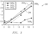
- FIG. 3 is a graph 350 depicting sensor data taken from the example sensing elements 242b of FIG. 2B .
- the graph 350 plots flow velocity (x-axis) as a function of sensor output (y-axis) for sensing elements 242b x , 242b y , and 242b z at positions x, y and z, respectively.
- the flow velocity of the sensing elements 242b y and 242b z at positions y and z are different from the flow velocity of the sensing element 242b x at position x.
- readings of the top sensing element 242b z and the 90-degree sensing element 242b y are substantially consistent in determining the flow velocity.
- the bottom sensing element 242b x has a flow velocity that is lower.
- the graph 350 indicates that the sensing element 242b x at position x is pressed against the wall 205 of the well 204 and is unable to obtain proper readings.
- the measurements depicted by line 242b x taken by sensing element 242b at position x may be disregarded.
- the measurements depicted as lines 242b y and 242b z taken by sensing elements 242b at positions y and z, respectively, may be combined using conventional analytical techniques (e.g., curve fitting, averaging, etc.) to generate an imposed flow 244.
- the azimuth of a flow obstruction may be determined.
- the sensing element located opposite to the lowest-reading sensing element (e.g., 242b y ), or combinations of other sensing elements, may then be used to perform the flow measurement.
- FIGS. 4A and 4B are schematic views of sensing elements 442p and 442q usable as the sensing elements 242a,b of FIGS. 2A and 2B .
- Each of the sensing elements 442p,q has a heater 454p,q and a sensor 456p,q, respectively, positioned in a sensor base 452.
- the sensor 456p,q is a temperature sensor (or temperature sensor) capable of measuring fluid temperature.
- the sensor elements 442p,q are calorimetric type flow sensors (or flow meters) that have two sensing elements such as, for example, a sensor for velocity measurement (scalar sensor) and a sensor for directional measurement (vector sensor).
- the heater 454p,q and the temperature sensor 456p,q interact to operate as velocity (or scalar) and directional (or vector) sensors.
- the sensing elements 442p,q act as calorimetric sensors.
- the heater 454p,q (or hot body) of each sensor elements 442p,q is placed in thermal contact with the fluid in the well 104.
- the rate of heat loss of the heater 454p,q to the fluid is a function of the fluid velocity as well as thermal properties.
- a heat dissipation rate of the heater 454p,q may be measured, and a flow velocity can be determined for a known fluid.
- the heater 454p,q generates heat (e.g., from electricity), and dissipates the heat to the fluid in contact. The rate of heat generation and the temperature may be readily measurable during operation.
- the temperature sensor 456p,q may be used to monitor ambient temperature of the fluid, while the heater 454p,q measures its own temperature during heating.
- the difference between the temperature of the heater 454p,q and the ambient temperature of the fluid is defined as temperature excursion.
- T a represents the ambient temperature of the fluid as measured by the temperature sensor
- T h represents the temperature of the heater
- the temperature excursion is proportional to the heater power at a given flow condition.
- Equation 2 P represents the heater power in steady state.
- the inverse of this proportionality correlates the flow velocity V flow because V flow is a function of G th .
- the thermal conductance is determined from three quantities: P (the heater power), T h (the temperature of the heater) and T a (the temperature of the fluid ambient). The quantities may be measured in steady state. Theoretically, the amount of power or temperature excursion used during measurement is immaterial to resultant thermal conductance. However, power and temperature excursion may affect accuracy because physical measurements have limits. In some cases, such as the configuration of FIG. 4B , a ⁇ T of a few degrees in Kelvin (K) may be considered appropriate.
- a normalized power dissipation is calculated to determine the flow velocity.
- the normalized power dissipation may be calculated according to the following expression: P S T h ⁇ T a .
- the normalized power dissipation is calculated by dividing the power of the heater by the temperature excursion and an area of a heating surface of the sensor, S.
- the measurements taken by the calorimetric sensing elements 454p,q may be used obtain the heater-fluid thermal conductance, the normalized dissipated power, and/or other thermal properties.
- a measurement technique may involve either constant excursion or constant power.
- power sent to the heater may be regulated by electronics (e.g., the control unit 136) such that the heater temperature may be maintained at a constant excursion above the fluid ambient temperature. In steady state, the power measured is monotonically related to the thermal conductance, the normalized power dissipation, and/or other thermal properties.
- the heater may be supplied with a constant and predetermined power, while the heater temperature T h varies and may be determined by flow velocity.
- FIG. 5A is a graph 657 depicting a flow response of a calorimetric sensor, such as the sensing elements 442a,b depicted in FIGS. 4A and 4B .
- the resulting thermal conductance verses flow curve 658 demonstrates that thermal conductance is non-linear relative to the flow velocity. However, the thermal conductance verses flow curve 658 is monotonic. Therefore, a correlation can be established to invert the measurement, and the flow velocity can be obtained as described in conjunction with Equations 1-2.
- the measurement of flow velocity is a measurement of the thermal conductance, the normalized power dissipation, and/or other thermal properties between the heater 454p,q and the fluid.
- the measurement of thermal conductance and/or the normalized power dissipation may be determined with constant temperature excursion ( ⁇ T) or constant heater power.
- the constant temperature excursion may regulate temperature.
- the constant heater power may regulate power. Either measurement technique may involve the heater 454p,q and the temperature sensor 456p,q.
- the sensing elements 442p,q may also act as scalar sensors to determine fluid direction.
- the sensing elements 442p,q are capable of acting as both calorimetric sensors for determining fluid velocity and vector sensors for measuring fluid direction.
- Calorimetric sensors may be unable to determine fluid direction.
- the calorimetric sensors may respond to fluid velocity regardless of direction.
- Fluid direction may be acquired by a second measurement, such as by using vector sensors capable of fluid direction detection. Fluid direction may also be acquired by, for example, the sensing elements 442p,q of FIGS. 4A and 4B configured for measurement of both fluid velocity and direction.
- Physics that enables directional detection may also involve detection of asymmetry in temperature between upstream and downstream sensing elements (e.g., caused by heat from the heater 454p of the upstream sensing element), such as the upstream sensing elements 242a and the downstream sensing elements 242b of FIG. 2A .
- FIGS. 4A and 4B depict configurations of the sensing element 442p,q capable of detecting both fluid flow rate and direction.
- FIG. 4A depicts a thermocouple (TC) sensing element 442p.
- FIG. 4B depicts a dual sensing element 442q.
- the base 452 for each sensing element 442p,q is sized for hosting the heater 454p,q, the sensor 456p,q and/or other devices therein.
- the base 452 has a minimum thickness, or is recessed in the downhole tool, to prevent damage in the well 104.
- the sensor base 452 is positionable downhole, for example, on the treatment device 122, 222 and/or the coiled tubing 114, 214 ( FIGS. 1 , 2A, 2B ).
- the base 452 may be round as shown in FIG. 4A or rectangular as shown in FIG. 4B .
- the base 452 may be made of epoxy, PEEK molding and/or any other material.
- the heater 454p,q and the temperature sensor 456p,q may be positioned in close proximity in base 452, but are thermally isolated from each other. In the illustrated example, because the heater 454p,q creates a temperature gradient in the fluid, the temperature sensor 456p,q is provided with sufficient thermal isolation from the heater 454p,q to prevent the temperature sensor 456p,q from being disturbed by the heat flux of the heater 454p,q or thermally coupling with the heater 454p,q, which may result in an erroneous measurement value.
- the temperature sensor 456p,q may optionally be positioned in a separate package spaced from the heater 454p,q.
- the TC sensing element 442p of FIG. 4A is depicted as having a pair of TC junctions (or sensors) 456p 1,2 on either side of a heating pad (or heater) 454p.
- the TC junctions 456p 1,2 are linked by a metal wire 460.
- Each TC junction 456p 1,2 has a TC pad with leads 462a,b extending therefrom.
- the leads 462 are also wires operatively coupled to a controller 436 for operation therewith.
- the TC junctions 456p positioned on either side of the heater 454p may be used to detect a temperature imbalance therebetween, and convert it into a TC voltage. A small voltage is present if the two TC junctions 456p 1,2 are at a different temperatures.
- the TC junctions 456p 1,2 are positioned very close to the heater 454p (one on each side) for maximum contrast of temperature. At zero flow, the heater 454p may heat up both TC junctions 456p 1,2 . However, the heating does not produce voltage.
- Two metal pads 464p are depicted as supporting the TC junctions 456p 1,2 .
- the metal pads 464p may be provided to improve the thermal contact between the TC junctions 456p 1,2 and the fluid.
- the metal pads 464p may be useful in cases where the TC junctions 456p 1,2 are of a small size.
- the metal pads 464p and the TC junctions 456p 1,2 may be held together by thermal adhesives such as silver epoxies or any other thermally conductive adhesives.
- the metal pads 464p are positioned in alignment with the heater 454p, thereby defining a flowline 466p along the sensing element 442p as indicated by the arrow.
- TC voltage (y-axis) as a function of flow velocity (x-axis) is show in a graph 659 of FIG. 5B .
- the graph 659 exhibits an odd function of the flow velocity measured by the TC junctions 456p 1,2 .
- the magnitude of a maxima near zero flow tapers off gradually with increasing velocity.
- the TC signal output undergoes an abrupt change in polarity from negative to positive as indicated by curves 661a,b, respectively. This change in signal polarity may be used to detect the fluid direction as described in greater detail below.
- FIG. 6 is a graph 663 depicting temperature (y-axis) versus velocity (x-axis).
- the heater 454p generates a constant heat T h measurable by the TC junction 456p 1,2 on either side thereof.
- Heat from the heater 454p is carried downstream by the fluid forming a hot stream.
- the velocity V1, V2 and V3 are measured at, for example, different time intervals. Visibility of the thermal gradient may depend on the velocity.
- the thermal gradient between upstream and downstream is detectable with the sensor element 442p. This creates a temperature contrast between the upstream and downstream TC junctions 456p 1,2 . This indicates that the flow is moving towards the TC junctions 456p 2 , thereby indicating fluid flow direction.
- the fluid direction can be determined as indicated by the arrow.
- the dual-element sensing element 442q of FIG. 4B is depicted as having two identical elements (sensors/heaters) 456q/454q.
- the sensors/heaters 456q/454q are depicted as Element M and Element N in the sensing element 442q.
- the heater 454q and the sensor 456q (and, therefore, Elements M and N) are interchangeable in function and operation.
- the sensor 456q is capable of performing the functions of the heater and the heater 454q is capable of performing the functions of the sensor.
- the Elements M and N are operatively linked via links 455 to the controller 436 for operation therewith.
- a desired measurement may be operated in self-referenced mode in which a single Element M or N plays a dual role, both as heater and as temperature sensor.
- the heater and the temperature sensor may utilize a time multiplexing technique.
- the role of the heater 454q and temperature sensor 456q may be reassigned at anytime. This measurement scheme may be used to provide flexibility in designing and/or operating the sensor element 442q, which may be tailored to a particular application.
- An asymmetry of temperature between the identical Elements M and N is detectable by the dual-element sensor 442q.
- the two identical Elements M and N are positioned along a line of flow of the fluid as indicated by the arrow.
- the Elements M and N may be positioned in close proximity, for example, within the same base (or package) 452.
- Measurement by the sensor element of FIG. 4B may be achieved using various methods.
- a first method involves measuring the heater power in flow using Element M as the heater and Element N as the temperature sensor. After a stable reading is attained, the roles of Elements M and N interchange and the measurement is repeated. Comparing the power of the two measurements, fluid direction can be ascertained. The heater that consumes more power is located upstream, provided that the flow does not vary in the meantime.
- a second method that may be used involves measuring by heating both elements M and N simultaneously with the same amount of power. The measurements of each element may be compared. Whichever element reveals a higher temperature is downstream in the direction of the fluid flow.
- a third method that may be used involves watching the temperature of Element M while switching on and off Element N at a certain power level. If an alteration of temperature is noticed, Element N may be assumed to be upstream of Element M. No change may suggest otherwise.
- the temperature sensor 456p,q and the heater 454p,q of FIGS. 4A and 4B reside in the same package (for instance, due to space constraint)
- the temperature sensor 456p,q is positioned upstream of the heater 454p,q (or element M is upstream of Element N). If flow goes in both directions, the temperature sensor 456p,q and heater 454p,q (or Elements M and N) may be positioned in a side-by-side (or flowline) configuration in line with the flow of the fluid as shown in the sensing elements 442p,q of FIGS. 4A and4B.
- FIG. 4A depicts a single heater 454p with a pair of TC junctions 456p and FIG. 4B depicts a single heater 454p with a single temperature sensor 456q
- other examples employ multiple heaters 454p,q and/or sensors 456p,q. Additional sensors and/or other devices may be incorporated into the sensing elements 442p,q and/or used in combination therewith.
- one temperature sensor 456p,q can serve multiple heaters 454p,q.
- Some multi-elements sensors have more than two elements (e.g., M, N, P, D ... ).
- a third element O may be provided.
- the three or more elements e.g., M, N, O
- the three or more elements may be used to detect fluid direction by heating a middle element and comparing the temperature between upstream and downstream elements thereabout.
- the sensing elements 442p,q of FIGS. 4A and 4B are operatively coupled to the controller 436 for providing power, collecting data, controlling and/or otherwise operating the sensing element 442p,q.
- the controller 436 may be, for example, the logging tool 128, the control unit 136 and/or other electronics capable of providing power, collecting data, controlling and/or otherwise operating the temperature sensors 456p,q, heater 456p,q and/or other elements of the sensing elements 442p,q.
- the power sources may be batteries, power supplies and/or other devices internal to and/or external to the sensing elements.
- other devices such as the logging tool 128 of FIG. 1A may provide power thereto.
- Such electronic devices may be internal and/or external to the sensing elements.
- Communication devices may be provided to wire and/or wirelessly coupled the sensing elements to downhole and/or surface communication devices for communication therewith.
- communication devices such as transceivers may be provided in the sensing elements.
- the sensing elements may be linked to the logging tool 128 ( FIG. 1A ) or other devices for communication as desired.
- the sensing elements are also operatively coupled to and/or in communication with databases, processors, analyzers, and/or other electronic devices for manipulating the data collected thereby.
- the power, electronic and/or communication devices may be used to manipulate data from the sensing elements, as well as other sources.
- the analyzed data may be used to make decisions concerning the wellsite and operation thereof. In some cases, the data may be used to control the well operation. Some such control may be done automatically and/or manually as desired.
- FIG. 7 depicts the sensor 770 usable as an element of the sensor elements 454p,q of FIGS. 4A and/or 4B.
- FIG. 7 depicts the sensor 770 usable as the heater 454q and/or the temperature sensor 456q, as elements M, N and/or O, or in combination therewith.
- the sensor 770 is positionable in the base 452.
- the sensor 770 may be operatively coupled to the controller 436 via wires 774 for operation therewith in the same manner as previously described for the sensor elements 442p,q.
- the example sensor 770 of FIG. 7 is an RTD type sensor with a resistance that varies with temperature.
- the sensor 770 is used for temperature sensing purposes.
- the sensor 770 may generate heat when current passes through the sensor 770.
- the example sensor 770 can be used both as a heater and a temperature sensor (e.g., 454p,q and 456p,q of FIG. 4B ).
- a thin-film type RTD capable of use as both a heater and temperature sensor may be used so that it can interchangeably operate as the Element M, N and/or O of FIG. 4B .
- the sensor 770 positioned in the base 452 has a front surface (or contact surface) 772 positionable adjacent the fluid for taking measurements therefrom.
- the sensor 770 employs platinum in the form of either wire or thin film (or resistor) 774 deposited on a heat-conductive substrate 776, such as sapphire or ceramic.
- the wire 774 is positioned in the film 776 and extends therefrom for operative linkage with the controller 436.
- the heat-conductive substrate 776 may be adhered or bonded to a thin pad 778 (made of, for example, Inconel or ceramic substrate) by a thermally conductive adhesive 780, such as silver epoxy, or by brazing. In some examples, such bonding provides low thermal resistance.
- the sensor 770 is wrapped in protective packaging, but they may differ by thermal mass and, hence, response time.
- the shape of the pad 778 may be square, circular or any other shape capable of supporting the RTD in the base 452.
- the pad 778 has a dimension of about 10 mm (or more or less), and a thickness sufficient for mechanical viability. The thickness and material selected may determine the performance of heater-fluid thermal contact.
- the example sensor 770 may be configured with a large surface area for contact with the fluid and/or large thermal mass for passage of heat therethrough. A larger thermal mass may result in a relatively slower measurement response. However, the thermal mass may also assist in reducing (e.g., averaging out) spurious variations in readings caused by turbulence. Sensor electronics may also be provided to reduce spurious variations.
- the sensor 770 and/or the sensing element 442q may be configured in a surface (or non-intrusive) form with a low profile (or thickness) as shown in FIGS. 7 and 4B .
- the sensor 770 and/or the sensing element 442q may be positionable downhole via a downhole tool (e.g., coiled tubing system 102 of FIG. 1A ) extending a small distance (if any) therefrom.
- This low profile or non-intrusive surface form may be provided to reduce the disturbance to the fluid flowing across the sensor, while still allowing for measurement of the fluid.
- the low profile surface form may also be configured to limit the amount of protrusion from the downhole the tool and, therefore, potential damage thereto.
- FIG. 8 illustrates the example sensing system 226, which may be used to determine a parameter of the well 104 (e.g., a cross-sectional area of the well 104, a width of the well 104, a distance from the example sensing system 226 to the wall 205 of the well 104, a diameter of the well 104, etc.) at a given depth.
- a form e.g., a shape of the well such as, for example, round, oblong, asymmetric, irregularly-shaped, etc.
- well dimensions may vary with the depth.
- a first cross-sectional area of the well 104 at a first depth 800 is greater than a second cross-sectional area of the well 104 at a second depth 802.
- the pump 115 pumps fluid through the well 104.
- the fluid flows through the well 104 in a direction of arrow 804.
- the fluid flows in other directions (e.g., toward a surface of Earth).
- the pump 115 pumps the fluid through the well 104 at a substantially constant flow rate.
- the fluid is pumped into the well via coiled tubing 806 and/or any other conveyance tool.
- the fluid is pumped through a sealed portion of the well 104 (e.g., a portion of the well 104 in which the fluid is not escaping into a production zone).
- a velocity of the fluid flowing through the well 104 varies as a function of the form and/or one or more dimensions of the well 104 such as, for example, the cross-sectional area of the well 104.
- the velocity of the fluid at the first depth 800 is less than the velocity of the fluid at the second depth 802.
- FIG. 9 is a cross-sectional view of the example well 104 of FIG. 8 at the first depth 800.
- the well 104 has an amebic cross-sectional shape.
- Other examples have other shapes (e.g., circular).
- the example sensing system 226 includes four of the sensing elements 242a disposed about a circumference of the coiled tubing system 102.
- Other examples include other numbers of the sensing elements 242a (e.g., 1, 2, 3, 5, 6, etc.), which may disposed about the circumference of the coiled tubing system 102 at other positions.
- the parameter of the well 104 at a given depth may be determined via one or more of the sensing elements 242a,b of the example sensing system 226 of FIG. 8 .
- the sensing system 226 may be lowered into the well 104 such that the sensing element 242a is positioned at the first depth 800.
- the sensing element 242a includes a heater and a temperature sensor (e.g., the example heater 454 of FIG. 4 , the example temperature sensor 456 of FIG. 4 , the example RTD sensor 770 of FIG. 7 ), which are used to determine a first velocity of the fluid at the first depth 800. Based on the first velocity of the fluid, a first parameter of the well 104 at the first depth 800 is determined.
- the first parameter of the well is associated with the first depth 800.
- the first depth 800 of the example sensing element 242a may be determined based on an amount (e.g., length) of the coiled tubing 114 deployed into the well 104 and/or via any suitable depth measuring device.
- the example sensing system 226 may be used to determine a plurality of parameters of the well 104 at a plurality of depths. Based on the plurality of parameters at the plurality of depths, a profile, (e.g., an image, a map, a model, a graph, a chart, a log, a table etc.) of a portion of the well 104 may be generated.
- a profile e.g., an image, a map, a model, a graph, a chart, a log, a table etc.
- FIGS. 10-11 are flowcharts representative of example methods disclosed herein. At least some of the example methods of FIGS. 10-11 may be carried out by a processor, the logging tool 128, the controller 436 and/or any other suitable processing device. In some examples, at least some of the example methods of FIGS. 10-11 are embodied in coded instructions stored on a tangible machine accessible or readable medium such as a flash memory, a ROM and/or random-access memory RAM associated with a processor. Some of the example methods of FIGS.
- FIGS. 10-11 may be implemented using any combination(s) of application specific integrated circuit(s) (ASIC(s)), programmable logic device(s) (PLD(s)), field programmable logic device(s) (FPLD(s)), discrete logic, hardware, firmware, etc. Also, one or more of the operations depicted in FIGS. 10-11 may be implemented manually or as any combination of any of the foregoing techniques, for example, any combination of firmware, software, discrete logic and/or hardware.
- ASIC application specific integrated circuit
- PLD programmable logic device
- FPLD field programmable logic device
- any of the example methods of FIGS. 10-11 may be carried out sequentially and/or carried out in parallel by, for example, separate processing threads, processors, devices, discrete logic, circuits, etc.
- FIG. 10 illustrates an example method 1000 disclosed herein that may be used to determine one or more fluid parameters.
- a downhole system such as, for example, the coiled tubing system 100 of FIG. 1A is deployed into a well with a sensor (e.g., one of the example sensor elements 242a,b of FIG. 2A ) thereon.
- the sensor includes a heater (e.g., the example heater 454 of FIG. 4 , the example RTD sensor 770 of FIG. 7 ) and a temperature sensor (e.g., the example temperature sensor 456 of FIG. 4 , the example RTD sensor 770 of FIG. 7 ).
- fluid is injected from the downhole system into the well via an injection port (e.g., the example injection port 224 of FIG. 2 ) of the downhole system.
- an injection port e.g., the example injection port 224 of FIG. 2
- a first measurement e.g., a temperature of the fluid
- a second measurement e.g., power dissipated via the heater, a temperature of the heater, etc.
- a fluid parameter e.g., a fluid velocity, a direction of fluid flow
- the fluid parameter is analyzed. In some examples, the measurements and/or the parameter are stored, processed, reported, and/or manipulated, etc.
- FIG. 11 illustrates another example method 1100 disclosed herein, which may be used to generate a profile of the well 104.
- the example method 1100 of FIG. 11 begins by disposing a sensor (e.g., the example sensor element 242a) of a downhole tool (e.g., the example coiled tubing system 102) in a well (block 1102).
- the sensor includes a heater (e.g., the example heater 454 of FIG. 4 ) and a temperature sensor (e.g., the example temperature sensor 456 of FIG. 4 ).
- fluid is flowed in the wellbore.
- the fluid is flowed (e.g., by the pump 115) at a substantially constant flow rate.
- a depth of the sensor is determined. In some examples, the depth of the sensor is determined based on an amount (e.g., length) of coiled tubing deployed into the well and/or via any suitable depth measuring device.
- the fluid is heated via the heater and, at block 1110, the temperature of the fluid is determined via the temperature sensor.
- a thermal property e.g., normalized power dissipation, thermal conductance, thermal resistance, etc.
- a velocity of the fluid at the depth is determined (block 1114).
- the velocity of the fluid varies as a function of a form (e.g., shape) of the well and/or one or more dimensions (e.g., a cross-sectional area) of the well.
- a parameter of the well e.g., a cross-section, the cross-sectional area, a width, a diameter, etc.
- the parameter of the well is associated with the depth (block 1118). For example, if a width of the well is one foot at one thousand feet below the surface, the width of one foot is associated with the depth of one thousand feet.
- the parameter associated with the depth is logged.
- the parameter associated with the depth may be stored in a database.
- a profile of the well is generated based on the parameter.
- an image, a map, a model, a graph, a chart, a table and/or any other profile of the well is generated based on the parameter associated with the depth stored in the database and/or any other information.
- the downhole tool is moved to position the sensing element at another depth in the well, and the example method returns to block 1106.
- the downhole tool may be traversed through a portion of the well and used to determine a first parameter of the well at a first depth, a second parameter of the well at a second depth, a third parameter of the well at a third depth, etc.
- a profile of the portion of the well through which the downhole tool is traversed may be generated.
Description
- A well may be drilled through a subterranean formation to extract hydrocarbons. A dimension (e.g., a cross-sectional area) of the well may vary with a depth of the well. Further, conditions in the well may be harsh. For example, temperatures inside the well may be from about negative 25 °C to about positive 150°C and pressures may be up to or exceed about 12,500 psi. Conventional calorimetric flow measuring methods like in
US 2006/0010973 are not suitable to provide such information, while other techniques like inEP 1435430 require more cost intensive methods. - This summary is provided to introduce a selection of concepts that are further described below in the detailed description. This summary is not intended to identify key or essential features of the claimed subject matter, nor is it intended to be used as an aid in limiting the scope of the claimed subject matter.
- An example method disclosed herein includes disposing a downhole tool in a well. The downhole tool includes a sensor having a heater and a temperature sensor. The example method further includes flowing a fluid in the well. The example method also includes determining a first velocity of the fluid at a first depth via the sensor and, based on the first velocity of the fluid, determining a first parameter of the well at the first depth.
- Another example method disclosed herein includes determining a first depth of a sensor of a downhole tool disposed in a well. The sensor includes a heater and a temperature sensor. The example method further includes determining a first velocity of a fluid in the well via the sensor and determining a first parameter of the well based on the first velocity of the fluid. The example method also includes associating the first parameter with the first depth and generating a profile of the well based on the first parameter.
- Another example method disclosed herein includes disposing a heater and a temperature sensor at a first depth. The example method further includes heating the fluid via the heater and determining a temperature of the fluid via the temperature sensor. Based on a thermal property between the heater and the fluid, a first velocity of the fluid at the first depth is determined. The example method also includes determining a first parameter of the well at the first depth based on the first velocity of the fluid.
- Embodiments of methods and apparatus for determining downhole parameters are described with reference to the following figures. The same numbers are used throughout the figures to reference like features and components.
-
FIG. 1A illustrates an example system in which embodiments of methods and apparatus for determining downhole parameters can be implemented. -
FIG. 1B illustrates various components of an example device that can implement embodiments of the methods and apparatus for determining downhole parameters. -
FIG. 1C illustrates various components of the example device ofFIG. 1B that can implement embodiments of the example methods and apparatus for determining downhole parameters. -
FIG. 1D illustrates various components of another example device that can implement embodiments of the methods and apparatus for determining downhole parameters. -
FIG. 2A illustrates various components of an example device that can implement embodiments of the methods and apparatus for determining downhole parameters. -
FIG. 2B illustrates various components of the example device ofFIG. 2A that can implement embodiments of the methods and apparatus for determining downhole parameters. -
FIG. 2C illustrates various components of the example device ofFIG. 2A that can implement embodiments of the methods and apparatus for determining downhole parameters. -
FIG. 2D illustrates various components of another example device that can implement embodiments of the methods and apparatus for determining downhole parameters. -
FIG. 2E illustrates various components of yet another example device that can implement embodiments of the methods and apparatus for determining downhole parameters. -
FIG. 3 is a graph depicting sensor measurements taken using the example device ofFIG. 2B . -
FIG. 4A illustrates various components of an example device that can implement embodiments of the methods and apparatus for determining downhole parameters. -
FIG. 4B illustrates various components of an example device that can implement embodiments of the methods and apparatus for determining downhole parameters. -
FIG. 5A is a graph illustrating sensor measurements. -
FIG. 5B is another graph illustrating sensor measurements. -
FIG. 6 is a graph of sensor measurements and fluid flow based on the sensor measurements. -
FIG. 7 illustrates various components of an example device that can implement embodiments of the methods and apparatus for determining downhole parameters. -
FIG. 8 illustrates various components of the example device ofFIG. 2E that can implement embodiments of the methods and apparatus for determining downhole parameters. -
FIG. 9 illustrates various components of the example device ofFIG. 8 that can implement embodiments of the methods and apparatus for determining downhole parameters. -
FIG. 10 illustrates example method(s) for determining downhole parameters in accordance with one or more embodiments. -
FIG. 11 illustrates example method(s) for determining downhole parameters in accordance with one or more embodiments. - It is to be understood that the following disclosure provides many different embodiments or examples for implementing different features of various embodiments. Specific examples of components and arrangements are described below to simplify the present disclosure. These are, of course, merely examples and are not intended to be limiting. In addition, the present disclosure may repeat reference numerals and/or letters in the various examples. This repetition is for the purpose of simplicity and clarity and does not in itself dictate a relationship between the various embodiments and/or configurations discussed. Moreover, the formation of a first feature over or on a second feature in the description that follows may include embodiments in which the first and second features are formed in direct contact, and may also include embodiments in which additional features may be formed interposing the first and second features such that the first and second features may not be in direct contact.
- Although some example fluid sensing systems disclosed herein are discussed as being positioned on treatment tools of a coiled tubing system, other examples are employed with and/or without treatment tools. For example, a fluid sensing element may be employed apart from the coiled tubing system. Thus, in some examples, the fluid sensing system may be deployed by a drill pipe, a drill string or any other suitable conveyance device.
- Example apparatus and methods disclosed herein may be used to determine downhole parameters. An example method disclosed herein may include disposing a downhole tool in a well. In some examples, the downhole tool includes a sensing element including a heater and a temperature sensor. The example method may include flowing a fluid in a well and determining a depth of the sensing element. In some examples, the heater heats the fluid and a temperature of the fluid is determined via the temperature sensor. Based on a thermal property between the heater and the fluid, a velocity of the fluid at the depth may be determined. A parameter (e.g., a width, a diameter, a cross-sectional area, etc.) of the well at the depth may be determined based on the velocity. In some examples, parameter is associated with the depth and logged (e.g., stored in a database). Based on the parameter of the well, a profile (e.g., a chart, a graph, a map, a model,a table, etc.) of the well may be generated.
-
FIG. 1A is a schematic depiction of a wellsite 100 with acoiled tubing system 102 deployed into a well 104. Thecoiled tubing system 102 includessurface delivery equipment 106, including a coiledtubing truck 108 withreel 110, positioned adjacent the well 104 at thewellsite 100. Thecoiled tubing system 102 also includes coiledtubing 114. In some examples, apump 115 is used to pump a fluid into the well 104 via the coiled tubing. With the coiledtubing 114 run through aconventional gooseneck injector 116 supported by amast 118 over the well 104, thecoiled tubing 114 may be advanced into thewell 104. That is, thecoiled tubing 114 may be forced down through valving andpressure control equipment 120 and into thewell 104. In thecoiled tubing system 102 as shown, atreatment device 122 is provided for delivering fluids downhole during a treatment application. Thetreatment device 122 is deployable into the well 104 to carry fluids, such as an acidizing agent or other treatment fluid, and disperse the fluids through at least oneinjection port 124 of thetreatment device 122. - The
example treatment device 122 is optional and its use will depend on the various applications. Thecoiled tubing system 102 ofFIG. 1A is depicted as having afluid sensing system 126 positioned about theinjection port 124 for determining parameters of fluids in thewell 104. Thefluid sensing system 126 is configured to determine fluid parameters, such as fluid direction and/or velocity. In other examples, other downhole parameters are determined. - In some examples, the
coiled tubing system 102 includes alogging tool 128 for collecting downhole data. Thelogging tool 128 as shown is provided near a downhole end of the coiledtubing 114. Thelogging tool 128 acquires a variety of logging data from the well 104 and surrounding formation layers 130, 132 such as those depicted inFIG. 1A . Thelogging tool 128 is provided with a host of well profile generating equipment or implements configured for production logging to acquire well fluids and formation measurements from which an overall production profile may be developed. Other logging, data acquisition, monitoring, imaging and/or other devices and/or capabilities may be provided to acquire data relative to a variety of well characteristics. Information gathered may be acquired at the surface in a high speed manner, and, where appropriate, put to immediate real-time use (e.g. via a treatment application). Some examples do not employ thelogging tool 128. - With reference still to
FIG. 1A , thecoiled tubing 114 with thetreatment device 122, thefluid sensing system 126 and thelogging tool 128 thereon is deployed downhole. As these components are deployed, treatment, sensing and/or logging applications may be directed by way of acontrol unit 136 at the surface. For example, thetreatment device 122 may be activated to release fluid from theinjection port 124; thefluid sensing system 126 may be activated to collect fluid measurements; and/or thelogging tool 128 may be activated to log downhole data, as desired. Thetreatment device 122, thefluid sensing system 126 and thelogging tool 128 are in communication with thecontrol unit 136 via a communication link (FIGS. 1B-1D ), which conveys signals (e.g., power, communication, control, etc.) therebetween. In some examples, the communication link is located in thelogging tool 128 and/or any other suitable location. As described in greater detail below, the communication link may be a hardwire link or an optical link. - In the illustrated example, the
control unit 136 is computerized equipment secured to thetruck 108. However, thecontrol unit 136 may be portable computerized equipment such as, for example, a smartphone, a laptop computer, etc. Additionally, powered controlling of the application may be hydraulic, pneumatic and/or electrical. In some examples, thecontrol unit 136 controls the operation, even in circumstances where subsequent different application assemblies are deployed downhole. That is, subsequent mobilization of control equipment may not be included. - The
control unit 136 may be configured to wirelessly communicate with atransceiver hub 138 of thecoiled tubing reel 110. Thereceiver hub 138 is configured for communication onsite (surface and/or downhole) and/or offsite as desired. In some examples, thecontrol unit 136 communicates with thesensing system 126 and/orlogging tool 128 for conveying data therebetween. Thecontrol unit 136 may be provided with and/or coupled to databases, processors, and/or communicators for collecting, storing, analyzing, and/or processing data collected from the sensing system and/or logging tool. - In one example, the communication link between the
treatment device 122,fluid sensing system 126 and/orlogging tool 128 and the surface orcontrol unit 136 may be implemented using a fiber optic or wired telemetry system. As such, the communication link/system may include tubing that provides and/or possesses a certain amount of stiffness in compression, similar to coiled tubing. In some such examples, a fiber optic tube is disposed inside coiled tubing. In some examples, a cross-sectional area of the fiber optic tube may be small relative to an inner area defined by the coiled tubing to limit a physical influence of the fiber optic tube on mechanical behavior of the coiled tubing during deployment and retrieval, thereby preventing "bird-nesting" or bundling within the coiled tubing. In some examples, optical fiber equipped coiled tubing is deployed into and retrieved from a wellbore at a greater speed than coiled tubing with wireline. -
FIG. 1B illustrates anexample communication link 200 between thetreatment device 122, thefluid sensing system 126, thelogging tool 128, and/or the surface orcontrol unit 136. In the illustrated example, thecommunication link 200 includes a tubular 105 within which a duct ortube 203 is disposed. In the illustrated example, anoptical fiber 201 is disposed in thetube 203. In some examples, more than one optical fiber is disposed in thetube 203. In the illustrated example, asurface termination 301 and adownhole termination 207 are provided to couple theoptical fiber 201 to one or more devices orsensors 209. In some examples, theoptical fiber 201 is a multi-mode optical fiber. In other examples, theoptical fiber 201 is a single-mode optical fiber. The devices orsensors 209 are, for example, gauges, valves, sampling devices, temperature sensors, pressure sensors, distributed temperature sensors, distributed pressure sensors, flow-control devices, flow rate measurement devices, oil/water/gas ratio measurement devices, scale detectors, actuators, locks, release mechanisms, equipment sensors (e.g., vibration sensors), sand detection sensors, water detection sensors, data recorders, viscosity sensors, density sensors, bubble point sensors, composition sensors, resistivity array devices and sensors, acoustic devices and sensors, other telemetry devices, near infrared sensors, gamma ray detectors, H2S detectors, CO2 detectors, downhole memory units, downhole controllers, perforating devices, shape charges, firing heads, locators, and other devices. -
FIG. 1C is a cross-sectional view of thecommunication link 200 ofFIG 1B . Inside thetube 203, an inert gas such as nitrogen may be used to fill the space between the optical fiber orfibers 201 and the interior of thetube 203. In some examples, the fluid is pressurized to prevent thetube 203 from buckling. In some examples, a laser-welding technique is performed in an enclosed environment filled with an inert gas such as, for example, nitrogen to avoid exposing theoptical fiber 201 to water or hydrogen during manufacturing. In some examples, thetube 203 is constructed by bending a metal strip around theoptical fiber 201 and then welding that strip to form thetube 203. An example laser-welding technique is described inUS Patent No 4,852,790 , which is hereby incorporated herein by reference in its entirety. In some examples, gel including palladium or tantalum is inserted into an end of thetube 203 to separate hydrogen ions from theoptical fiber 201 during transportation of thecommunication link 200. - Materials suitable for use in the
tube 203 provide stiffness to thetube 203, are resistant to fluids encountered in oilfield applications, and/or are rated to withstand the high temperature and high pressure conditions found in some wellbore environments. In some examples, thetube 203 is a metallic material and thetube 203 may include metal materials such as, for example, InconelTM, stainless steel, or HasetloyTM. - In some examples, the
tube 203 has an outer diameter of about 0.071 inches to about 0.125 inches. In some examples, thetube 203 is less than or equal to about 0.020 inches (0.508 mm) thick. The above-noted dimensions are merely examples and, thus, other dimensions may be used without departing from the scope of this disclosure -
FIG. 1D illustrates anotherexample communication link 212. In the illustrated example, thecommunication link 212 includes a tubular 105 and afirst tube 203 and asecond tube 203. A firstoptical fiber 201 is disposed in the first tube. A secondoptical fiber 201 and a thirdoptical fiber 201 are disposed in thesecond tube 203. In some example, the firstoptical fiber 201 is coupled to one of thedevices 209, and the secondoptical fiber 201 and the thirdoptical fiber 201 are coupled to one or more other ones of thedevices 209. In some examples, more than one of thedevices 209 may be coupled to a singleoptical fiber 201. -
FIGS. 2A-2C are schematic views of a portion of acoiled tubing system 202 with atreatment device 222 andfluid sensing system 226 on acoiled tubing 214 thereof, which may be used to implement the coiledtubing system 102, thetreatment device 122 and/or thefluid sensing system 126 ofFIG. 1A .FIG. 2A is a longitudinal view, partially in cross-section, depicting thefluid sensing system 226 positioned about thetreatment device 222. As shown, thetreatment device 222 hasinjection ports 224 for dispersing injection fluids into a well 204 as schematically depicted by the dashed arrows. - The injection fluid may be dispersed to treat a portion of a well 204, such as
pay zone 240, to enhance production of fluid therefrom. As illustrated inFIG. 2A , stimulation fluid, such as acid, may be injected into the well 204 nearby the pay (or oil producing)zone 240 by means of thetreatment tool 222. The acid is intended for thepay zone 240, but is shown positioned downhole therefrom. Precisely positioning theinjection ports 224 against a zone of interest may be a challenging task due to uncertainties that may exist in target depth and/or tool position. Thesensing system 226 around theinjection port 224 may be tailored to measure a flow split upstream and downstream of theinjection ports 224 in thewell 204. Fluid movement may be used to indicate where thepay zone 240 is located relative to theinjection port 224. Once known, the position of thetreatment device 222 and theinjection ports 224 may be positioned to affect treatment as desired. - As the fluid is released from the
treatment device 222, the flow of the fluid is split with an upstream portion of the fluid moving upstream and a downstream portion of the injection fluid moving downstream. The upstream portion of the injection fluid travels upstream at a given velocity as indicated by the arrows labeled V1. The downstream portion of the injection fluid travels downstream at a given velocity as indicated by the arrows labeled V2. While the fluid is depicted as flowing in a specific direction, it will be appreciated that the flow of the fluid may vary with operating conditions. - While the
example sensing system 226 illustrated inFIGS. 1 and2A-2C is described in conjunction with thecoiled tubing system 102 for determining fluid parameters, thesensing system 226 may also be used in other fluid flow applications such as, for example, detection of fluid cross-flow between zones, production logging (e.g., for single phase velocity, or in conjunction with Flow Scanner Imaging (FSI) complementary to a spinner in a low velocity range), downhole or surface testing in conjunction with use of a flowmeter (e.g., low speed Venturi based flowmeter applications), leakage detection (e.g., with dynamic seals), with other tools where flow velocity measurements is desired, among others. Thesensing system 226 may be positioned on any surface, downhole and/or other movable equipment, such as a downhole tool, and/or in fixed equipment, such as a casing (not shown). - The
sensing system 226 is depicted inFIG. 2A as having a plurality ofsensor elements 242a,b positioned about thetreatment device 222. In some examples, one ormore sensor elements 242 a,b are positioned about the coiledtubing system 102 to perform fluid and/or other downhole measurements. In some such examples, thesensor elements 242a,b are positioned about the injection port(s) 224 to measure fluid parameters. The fluid measured is the injection fluid dispersed from thetreatment device 222, but may also include other fluids in the well (e.g., water, hydrocarbons, gases, etc.) that mix with the injection fluid as it is dispersed. - An upstream portion of the
sensor elements 242a are depicted as being positioned on the treatment device 222 a distance upstream therefrom. A downstream portion of thesensor elements 242b are depicted as being positioned on the treatment device 222 a distance downstream therefrom. Theupstream sensor elements 242a and/or thedownstream sensor elements 242b may be arranged radially about thetreatment apparatus 222. In the illustrated example ofFIG. 2B , thesensor elements 242a,b are positioned at various radial locations x,y,z about thetreatment apparatus 222. While a specific configuration for thesensor elements 242a,b is depicted inFIGS. 2A and 2B , it will be appreciated that one or more sensor elements may be positioned at various locations (longitudinally and/or radially) about the coiledtubing system 202 and/or well 204. - At least some of the
sensor elements 242a,b are capable of sensing fluid parameters, such as fluid direction and velocity. In some examples, more than one of thesensor elements 242a,b may be capable of measuring the fluid parameters. In some examples, at least one of thesensor elements 242a for measuring fluid parameters is positioned upstream from theinjection port 224, and at least one of thesensor elements 242b for measuring fluid parameters is positioned downstream from theinjection port 224. In this configuration, the measurements of the upstream and thedownstream fluid sensors 242a,b may be compared to determine fluid parameters, such as fluid direction and/or fluid velocity. The ratio between upper and lower velocities and fluid direction obtained from measurements of the upstream anddownstream sensing elements 242a,b may be used to generate real-time monitoring of where the fluid is flowing during the treatment, as will be described further herein. Other downhole parameters may also optionally be measured with thefluid sensing system 226 and/or other sensors positioned about the well. - Comparison of
multiple sensing elements 242a,b may be used to account for differences in measurements taken by thevarious sensing elements 242a,b. In some examples,multiple sensing elements 242a,b are used to provide sufficient redundancy and confidence in the measurement results. This redundancy may also reduce the severity of impact where one ormore sensor elements 242a,b fails, such as in harsh downhole environments involving the use of acids. Themultiple sensing elements 242a,b may also be used to generate fluid direction and/or velocity information. In such cases, at least oneupstream sensor element 242a and at least onedownstream sensor element 242b may be used. In some examples,additional sensor elements 242a,b are provided to enhance reliability of the values generated. - In some examples, it may be useful to consider the position of the
sensing element 242a,b about thetreatment tool 222. The number of arrays (or sets ofsensing elements 242a,b), as well as the number ofsensing elements 242a,b per array, may vary. As shown inFIG. 2A , thesensing elements 242a,b are positioned upstream and downstream to measure fluid as it passes upstream and downstream from theinjection ports 224. In some examples, when using corresponding upstream anddownstream sensing elements 242a,b, the correspondingsensing elements 242a,b, are positioned at equal distances from theinjection port 224. In some examples, correspondingsensing elements 242a,b are identically matched. Matched sensing elements may be spaced at equal distances. - In the illustrated example,
multiple sensing elements 242a,b are also positioned about the circumference of the tool at 90-degree intervals x, y, and z as shown inFIG. 2B . As shown inFIG. 2B , thesensing elements 242b are positioned at radial locations x, y and z about thetreatment device 222. Thesensing element 242b at position x is against awall 205 of thewell 204. The azimuthal arrangement ofsensing elements 242a,b at positions x, y, and z provides redundancy in case one side of measurements is impeded. - An issue may appear when the tool body (e.g., the treatment tool 222) is eccentric (or not concentric) with the well 204 as shown in
FIG. 2B . In the illustrated example, thesensing element 242bx located closer to thewall 205 of the well 204 may read a lower flow value than thesensing elements sensing element 242bx. - As shown in
FIG. 2B , thesensing elements 242b are positioned on anouter surface 223 of thetreatment tool 222. Thesensing elements 242b may be flush with theouter surface 223, recessed below theouter surface 223 or extended a distance therefrom. In some examples, thesensing elements 242b are positioned such that eachsensing element 242b contacts fluid for measurement thereof, but remains protected. To prevent damage in harsh downhole conditions, protrusion of thesensing elements 242b from the treatment tool may be reduced. As shown inFIG. 2C , thesensing elements 242b may also be positioned inside thetreatment tool 222, for example, on aninner surface 225 thereof. -
FIGS. 2D and 2E illustrate other portions of the coiledtubing system 202 including thefluid sensing system 226, which may be used to implement the example coiledtubing system 102 ofFIG. 1A . InFIG. 2D , theexample sensing system 226 is disposed at a lower end of the coiledtubing 114. - In
FIG. 2E , theexample sensing system 226 is disposed between thelogging tool 128 and thetreatment tool 122. In the illustrated example, thelogging tool 128 is disposed above thesensing system 226 and thetreatment tool 122 is disposed below thesensing system 226 in the orientation ofFIG. 2E . In some examples, the fluid enters the well 104 as shown by arrows V3. In other examples, thesensing system 226 is disposed at one or more other locations on thecoiled tubing 114. -
FIG. 3 is agraph 350 depicting sensor data taken from theexample sensing elements 242b ofFIG. 2B . Thegraph 350 plots flow velocity (x-axis) as a function of sensor output (y-axis) for sensingelements graph 350, the flow velocity of thesensing elements sensing element 242bx at position x. In other words, readings of thetop sensing element 242bz and the 90-degree sensing element 242by are substantially consistent in determining the flow velocity. However thebottom sensing element 242bx has a flow velocity that is lower. - The
graph 350 indicates that thesensing element 242bx at position x is pressed against thewall 205 of the well 204 and is unable to obtain proper readings. Thus, the measurements depicted byline 242bx taken by sensingelement 242b at position x may be disregarded. The measurements depicted aslines elements 242b at positions y and z, respectively, may be combined using conventional analytical techniques (e.g., curve fitting, averaging, etc.) to generate an imposedflow 244. Thus, by placingseveral sensing elements 242a,b azimuthally around the circumference of a tool and detecting the lowest reading sensing element (e.g., 242bx), the azimuth of a flow obstruction may be determined. The sensing element located opposite to the lowest-reading sensing element (e.g., 242by), or combinations of other sensing elements, may then be used to perform the flow measurement. -
FIGS. 4A and 4B are schematic views of sensing elements 442p and 442q usable as thesensing elements 242a,b ofFIGS. 2A and 2B . Each of the sensing elements 442p,q has aheater 454p,q and a sensor 456p,q, respectively, positioned in asensor base 452. In the illustrated example, the sensor 456p,q is a temperature sensor (or temperature sensor) capable of measuring fluid temperature. - In some examples, the sensor elements 442p,q are calorimetric type flow sensors (or flow meters) that have two sensing elements such as, for example, a sensor for velocity measurement (scalar sensor) and a sensor for directional measurement (vector sensor). The
heater 454p,q and the temperature sensor 456p,q interact to operate as velocity (or scalar) and directional (or vector) sensors. - To determine fluid velocity, the sensing elements 442p,q act as calorimetric sensors. The
heater 454p,q (or hot body) of each sensor elements 442p,q is placed in thermal contact with the fluid in thewell 104. The rate of heat loss of theheater 454p,q to the fluid is a function of the fluid velocity as well as thermal properties. A heat dissipation rate of theheater 454p,q may be measured, and a flow velocity can be determined for a known fluid. Theheater 454p,q generates heat (e.g., from electricity), and dissipates the heat to the fluid in contact. The rate of heat generation and the temperature may be readily measurable during operation. - The temperature sensor 456p,q may be used to monitor ambient temperature of the fluid, while the
heater 454p,q measures its own temperature during heating. The difference between the temperature of theheater 454p,q and the ambient temperature of the fluid is defined as temperature excursion. The temperature excursion, ΔT, may be written as follows:
- In
Equation 1, Ta represents the ambient temperature of the fluid as measured by the temperature sensor; Th represents the temperature of the heater; and the temperature excursion is proportional to the heater power at a given flow condition. A thermal property between the heater and the fluid such as, for example, thermal conductance, Gth, may be calculated according to following expression:
- In
Equation 2, P represents the heater power in steady state. The inverse of this proportionality (or the thermal conductance) correlates the flow velocity Vflow because Vflow is a function of Gth. As provided byEquation 1, the thermal conductance is determined from three quantities: P (the heater power), Th (the temperature of the heater) and Ta (the temperature of the fluid ambient). The quantities may be measured in steady state. Theoretically, the amount of power or temperature excursion used during measurement is immaterial to resultant thermal conductance. However, power and temperature excursion may affect accuracy because physical measurements have limits. In some cases, such as the configuration ofFIG. 4B , a ΔT of a few degrees in Kelvin (K) may be considered appropriate. - In other examples, other thermal properties such as, for example, a normalized power dissipation are calculated to determine the flow velocity. The normalized power dissipation may be calculated according to the following expression:

Equation 3, the normalized power dissipation is calculated by dividing the power of the heater by the temperature excursion and an area of a heating surface of the sensor, S. - The measurements taken by the
calorimetric sensing elements 454p,q may be used obtain the heater-fluid thermal conductance, the normalized dissipated power, and/or other thermal properties. A measurement technique may involve either constant excursion or constant power. For the constant excursion technique, power sent to the heater may be regulated by electronics (e.g., the control unit 136) such that the heater temperature may be maintained at a constant excursion above the fluid ambient temperature. In steady state, the power measured is monotonically related to the thermal conductance, the normalized power dissipation, and/or other thermal properties. For the constant power technique, the heater may be supplied with a constant and predetermined power, while the heater temperature Th varies and may be determined by flow velocity. -
FIG. 5A is a graph 657 depicting a flow response of a calorimetric sensor, such as the sensing elements 442a,b depicted inFIGS. 4A and 4B . The resulting thermal conductance verses flowcurve 658 demonstrates that thermal conductance is non-linear relative to the flow velocity. However, the thermal conductance verses flowcurve 658 is monotonic. Therefore, a correlation can be established to invert the measurement, and the flow velocity can be obtained as described in conjunction with Equations 1-2. - The measurement of flow velocity is a measurement of the thermal conductance, the normalized power dissipation, and/or other thermal properties between the
heater 454p,q and the fluid. The measurement of thermal conductance and/or the normalized power dissipation may be determined with constant temperature excursion (ΔT) or constant heater power. The constant temperature excursion may regulate temperature. The constant heater power may regulate power. Either measurement technique may involve theheater 454p,q and the temperature sensor 456p,q. - Referring back to
FIGS. 4A and 4B , the sensing elements 442p,q may also act as scalar sensors to determine fluid direction. In the illustrated example, the sensing elements 442p,q are capable of acting as both calorimetric sensors for determining fluid velocity and vector sensors for measuring fluid direction. Calorimetric sensors may be unable to determine fluid direction. In such examples, the calorimetric sensors may respond to fluid velocity regardless of direction. Fluid direction may be acquired by a second measurement, such as by using vector sensors capable of fluid direction detection. Fluid direction may also be acquired by, for example, the sensing elements 442p,q ofFIGS. 4A and 4B configured for measurement of both fluid velocity and direction. Physics that enables directional detection may also involve detection of asymmetry in temperature between upstream and downstream sensing elements (e.g., caused by heat from theheater 454p of the upstream sensing element), such as theupstream sensing elements 242a and thedownstream sensing elements 242b ofFIG. 2A . -
FIGS. 4A and 4B depict configurations of the sensing element 442p,q capable of detecting both fluid flow rate and direction.FIG. 4A depicts a thermocouple (TC) sensing element 442p.FIG. 4B depicts a dual sensing element 442q. Thebase 452 for each sensing element 442p,q is sized for hosting theheater 454p,q, the sensor 456p,q and/or other devices therein. - In some examples, the
base 452 has a minimum thickness, or is recessed in the downhole tool, to prevent damage in thewell 104. Thesensor base 452 is positionable downhole, for example, on thetreatment device coiled tubing 114, 214 (FIGS. 1 ,2A, 2B ). The base 452 may be round as shown inFIG. 4A or rectangular as shown inFIG. 4B . The base 452 may be made of epoxy, PEEK molding and/or any other material. - The
heater 454p,q and the temperature sensor 456p,q may be positioned in close proximity inbase 452, but are thermally isolated from each other. In the illustrated example, because theheater 454p,q creates a temperature gradient in the fluid, the temperature sensor 456p,q is provided with sufficient thermal isolation from theheater 454p,q to prevent the temperature sensor 456p,q from being disturbed by the heat flux of theheater 454p,q or thermally coupling with theheater 454p,q, which may result in an erroneous measurement value. The temperature sensor 456p,q may optionally be positioned in a separate package spaced from theheater 454p,q. - The TC sensing element 442p of
FIG. 4A is depicted as having a pair of TC junctions (or sensors) 456p1,2 on either side of a heating pad (or heater) 454p. The TC junctions 456p1,2 are linked by ametal wire 460. Each TC junction 456p1,2 has a TC pad with leads 462a,b extending therefrom. In some examples, the leads 462 are also wires operatively coupled to acontroller 436 for operation therewith. - The TC junctions 456p positioned on either side of the
heater 454p may be used to detect a temperature imbalance therebetween, and convert it into a TC voltage. A small voltage is present if the two TC junctions 456p1,2 are at a different temperatures. The TC junctions 456p1,2 are positioned very close to theheater 454p (one on each side) for maximum contrast of temperature. At zero flow, theheater 454p may heat up both TC junctions 456p1,2. However, the heating does not produce voltage. - Two
metal pads 464p are depicted as supporting the TC junctions 456p1,2. Themetal pads 464p may be provided to improve the thermal contact between the TC junctions 456p1,2 and the fluid. Themetal pads 464p may be useful in cases where the TC junctions 456p1,2 are of a small size. Themetal pads 464p and the TC junctions 456p1,2 may be held together by thermal adhesives such as silver epoxies or any other thermally conductive adhesives. Themetal pads 464p are positioned in alignment with theheater 454p, thereby defining aflowline 466p along the sensing element 442p as indicated by the arrow. - TC voltage (y-axis) as a function of flow velocity (x-axis) is show in a
graph 659 ofFIG. 5B . Thegraph 659 exhibits an odd function of the flow velocity measured by the TC junctions 456p1,2. The magnitude of a maxima near zero flow tapers off gradually with increasing velocity. At zero crossing, the TC signal output undergoes an abrupt change in polarity from negative to positive as indicated bycurves 661a,b, respectively. This change in signal polarity may be used to detect the fluid direction as described in greater detail below. - The temperature profile along a flow stream of, for example, the sensing element 442p is shown schematically in
FIG. 6. FIG. 6 is agraph 663 depicting temperature (y-axis) versus velocity (x-axis). As depicted by this graph, theheater 454p generates a constant heat Th measurable by the TC junction 456p1,2 on either side thereof. Heat from theheater 454p is carried downstream by the fluid forming a hot stream. The velocity V1, V2 and V3 are measured at, for example, different time intervals. Visibility of the thermal gradient may depend on the velocity. The thermal gradient between upstream and downstream is detectable with the sensor element 442p. This creates a temperature contrast between the upstream and downstream TC junctions 456p1,2. This indicates that the flow is moving towards the TC junctions 456p2, thereby indicating fluid flow direction. By detecting asymmetry between the TC junctions 456p1,2, the fluid direction can be determined as indicated by the arrow. - The dual-element sensing element 442q of
FIG. 4B is depicted as having two identical elements (sensors/heaters) 456q/454q. The sensors/heaters 456q/454q are depicted as Element M and Element N in the sensing element 442q. In some examples, the heater 454q and thesensor 456q (and, therefore, Elements M and N) are interchangeable in function and operation. In some such cases, thesensor 456q is capable of performing the functions of the heater and the heater 454q is capable of performing the functions of the sensor. The Elements M and N are operatively linked vialinks 455 to thecontroller 436 for operation therewith. - In some examples, a desired measurement may be operated in self-referenced mode in which a single Element M or N plays a dual role, both as heater and as temperature sensor. In some such cases, the heater and the temperature sensor may utilize a time multiplexing technique. In some examples, the role of the heater 454q and
temperature sensor 456q may be reassigned at anytime. This measurement scheme may be used to provide flexibility in designing and/or operating the sensor element 442q, which may be tailored to a particular application. - An asymmetry of temperature between the identical Elements M and N is detectable by the dual-element sensor 442q. The two identical Elements M and N are positioned along a line of flow of the fluid as indicated by the arrow. The Elements M and N may be positioned in close proximity, for example, within the same base (or package) 452.
- Measurement by the sensor element of
FIG. 4B may be achieved using various methods. A first method involves measuring the heater power in flow using Element M as the heater and Element N as the temperature sensor. After a stable reading is attained, the roles of Elements M and N interchange and the measurement is repeated. Comparing the power of the two measurements, fluid direction can be ascertained. The heater that consumes more power is located upstream, provided that the flow does not vary in the meantime. A second method that may be used involves measuring by heating both elements M and N simultaneously with the same amount of power. The measurements of each element may be compared. Whichever element reveals a higher temperature is downstream in the direction of the fluid flow. A third method that may be used involves watching the temperature of Element M while switching on and off Element N at a certain power level. If an alteration of temperature is noticed, Element N may be assumed to be upstream of Element M. No change may suggest otherwise. - With the first two methods, where quantities are compared across Elements M and N, a good match of characteristics of the two elements M, N reduces potential errors. The match of elements may be achieved by calibration and normalization. The third method, on the other hand, may be used without as good of a match. Dual-element sensors are usable, for example, for bidirectional flow.
- When the temperature sensor 456p,q and the
heater 454p,q ofFIGS. 4A and 4B reside in the same package (for instance, due to space constraint), the temperature sensor 456p,q is positioned upstream of theheater 454p,q (or element M is upstream of Element N). If flow goes in both directions, the temperature sensor 456p,q andheater 454p,q (or Elements M and N) may be positioned in a side-by-side (or flowline) configuration in line with the flow of the fluid as shown in the sensing elements 442p,q ofFIGS. 4A and4B. - While
FIG. 4A depicts asingle heater 454p with a pair of TC junctions 456p andFIG. 4B depicts asingle heater 454p with asingle temperature sensor 456q, other examples employmultiple heaters 454p,q and/or sensors 456p,q. Additional sensors and/or other devices may be incorporated into the sensing elements 442p,q and/or used in combination therewith. In sensor systems includingmultiple heaters 454p,q, one temperature sensor 456p,q can servemultiple heaters 454p,q. Some multi-elements sensors have more than two elements (e.g., M, N, P, D ... ). As shown inFIG. 4B , a third element O may be provided. In another method of measurement, the three or more elements (e.g., M, N, O) may be used to detect fluid direction by heating a middle element and comparing the temperature between upstream and downstream elements thereabout. - As shown, the sensing elements 442p,q of
FIGS. 4A and 4B (and/or the sensors, heaters, elements and/or other components used therein and/or therewith) are operatively coupled to thecontroller 436 for providing power, collecting data, controlling and/or otherwise operating the sensing element 442p,q. Thecontroller 436 may be, for example, thelogging tool 128, thecontrol unit 136 and/or other electronics capable of providing power, collecting data, controlling and/or otherwise operating the temperature sensors 456p,q, heater 456p,q and/or other elements of the sensing elements 442p,q. The power sources may be batteries, power supplies and/or other devices internal to and/or external to the sensing elements. In some cases, other devices such as thelogging tool 128 ofFIG. 1A may provide power thereto. Such electronic devices may be internal and/or external to the sensing elements. Communication devices may be provided to wire and/or wirelessly coupled the sensing elements to downhole and/or surface communication devices for communication therewith. In some cases, communication devices, such as transceivers may be provided in the sensing elements. In other cases, the sensing elements may be linked to the logging tool 128 (FIG. 1A ) or other devices for communication as desired. - The sensing elements are also operatively coupled to and/or in communication with databases, processors, analyzers, and/or other electronic devices for manipulating the data collected thereby. The power, electronic and/or communication devices may be used to manipulate data from the sensing elements, as well as other sources. The analyzed data may be used to make decisions concerning the wellsite and operation thereof. In some cases, the data may be used to control the well operation. Some such control may be done automatically and/or manually as desired.
- While elements of the heater and the temperature sensor may be physically identical, the sensor can have a variety of types, forms and/or shapes.
FIG. 7 depicts thesensor 770 usable as an element of thesensor elements 454p,q ofFIGS. 4A and/or 4B.FIG. 7 depicts thesensor 770 usable as the heater 454q and/or thetemperature sensor 456q, as elements M, N and/or O, or in combination therewith. A shown, thesensor 770 is positionable in thebase 452. Thesensor 770 may be operatively coupled to thecontroller 436 viawires 774 for operation therewith in the same manner as previously described for the sensor elements 442p,q. - The
example sensor 770 ofFIG. 7 is an RTD type sensor with a resistance that varies with temperature. In some examples, thesensor 770 is used for temperature sensing purposes. However, thesensor 770 may generate heat when current passes through thesensor 770. Thus, theexample sensor 770 can be used both as a heater and a temperature sensor (e.g., 454p,q and 456p,q ofFIG. 4B ). - A thin-film type RTD capable of use as both a heater and temperature sensor may be used so that it can interchangeably operate as the Element M, N and/or O of
FIG. 4B . As shown inFIG. 7 , thesensor 770 positioned in thebase 452 has a front surface (or contact surface) 772 positionable adjacent the fluid for taking measurements therefrom. In some examples, thesensor 770 employs platinum in the form of either wire or thin film (or resistor) 774 deposited on a heat-conductive substrate 776, such as sapphire or ceramic. Thewire 774 is positioned in thefilm 776 and extends therefrom for operative linkage with thecontroller 436. The heat-conductive substrate 776 may be adhered or bonded to a thin pad 778 (made of, for example, Inconel or ceramic substrate) by a thermallyconductive adhesive 780, such as silver epoxy, or by brazing. In some examples, such bonding provides low thermal resistance. - In the illustrated example, the
sensor 770 is wrapped in protective packaging, but they may differ by thermal mass and, hence, response time. The shape of thepad 778 may be square, circular or any other shape capable of supporting the RTD in thebase 452. In some examples, thepad 778 has a dimension of about 10 mm (or more or less), and a thickness sufficient for mechanical viability. The thickness and material selected may determine the performance of heater-fluid thermal contact. - The
example sensor 770 may be configured with a large surface area for contact with the fluid and/or large thermal mass for passage of heat therethrough. A larger thermal mass may result in a relatively slower measurement response. However, the thermal mass may also assist in reducing (e.g., averaging out) spurious variations in readings caused by turbulence. Sensor electronics may also be provided to reduce spurious variations. - The
sensor 770 and/or the sensing element 442q may be configured in a surface (or non-intrusive) form with a low profile (or thickness) as shown inFIGS. 7 and4B . Thesensor 770 and/or the sensing element 442q may be positionable downhole via a downhole tool (e.g.,coiled tubing system 102 ofFIG. 1A ) extending a small distance (if any) therefrom. This low profile or non-intrusive surface form may be provided to reduce the disturbance to the fluid flowing across the sensor, while still allowing for measurement of the fluid. Moreover, the low profile surface form may also be configured to limit the amount of protrusion from the downhole the tool and, therefore, potential damage thereto. -
FIG. 8 illustrates theexample sensing system 226, which may be used to determine a parameter of the well 104 (e.g., a cross-sectional area of the well 104, a width of the well 104, a distance from theexample sensing system 226 to thewall 205 of the well 104, a diameter of the well 104, etc.) at a given depth. In some examples, a form (e.g., a shape of the well such as, for example, round, oblong, asymmetric, irregularly-shaped, etc.) of the well 104 varies with depth. As a result, well dimensions may vary with the depth. In the illustrated example, a first cross-sectional area of the well 104 at afirst depth 800 is greater than a second cross-sectional area of the well 104 at asecond depth 802. - In some examples, the
pump 115 pumps fluid through thewell 104. In the illustrated example, the fluid flows through the well 104 in a direction ofarrow 804. In other examples, the fluid flows in other directions (e.g., toward a surface of Earth). In some examples, thepump 115 pumps the fluid through the well 104 at a substantially constant flow rate. In some examples, the fluid is pumped into the well via coiledtubing 806 and/or any other conveyance tool. In some such examples, the fluid is pumped through a sealed portion of the well 104 (e.g., a portion of the well 104 in which the fluid is not escaping into a production zone). As a result, a velocity of the fluid flowing through the well 104 varies as a function of the form and/or one or more dimensions of the well 104 such as, for example, the cross-sectional area of thewell 104. For example, because the cross-sectional area of the well 104 at thefirst depth 800 is greater than the cross-sectional area of the well 104 at the second depth, the velocity of the fluid at thefirst depth 800 is less than the velocity of the fluid at thesecond depth 802. -
FIG. 9 is a cross-sectional view of the example well 104 ofFIG. 8 at thefirst depth 800. In the illustrated example, the well 104 has an amebic cross-sectional shape. Other examples have other shapes (e.g., circular). Theexample sensing system 226 includes four of thesensing elements 242a disposed about a circumference of the coiledtubing system 102. Other examples include other numbers of thesensing elements 242a (e.g., 1, 2, 3, 5, 6, etc.), which may disposed about the circumference of the coiledtubing system 102 at other positions. - The parameter of the well 104 at a given depth may be determined via one or more of the
sensing elements 242a,b of theexample sensing system 226 ofFIG. 8 . For example, thesensing system 226 may be lowered into the well 104 such that thesensing element 242a is positioned at thefirst depth 800. In some examples, thesensing element 242a includes a heater and a temperature sensor (e.g., the example heater 454 ofFIG. 4 , the example temperature sensor 456 ofFIG. 4 , theexample RTD sensor 770 ofFIG. 7 ), which are used to determine a first velocity of the fluid at thefirst depth 800. Based on the first velocity of the fluid, a first parameter of the well 104 at thefirst depth 800 is determined. In some examples, the first parameter of the well is associated with thefirst depth 800. Thefirst depth 800 of theexample sensing element 242a may be determined based on an amount (e.g., length) of the coiledtubing 114 deployed into the well 104 and/or via any suitable depth measuring device. - In some examples, the
example sensing system 226 may be used to determine a plurality of parameters of the well 104 at a plurality of depths. Based on the plurality of parameters at the plurality of depths, a profile, (e.g., an image, a map, a model, a graph, a chart, a log, a table etc.) of a portion of the well 104 may be generated. -
FIGS. 10-11 are flowcharts representative of example methods disclosed herein. At least some of the example methods ofFIGS. 10-11 may be carried out by a processor, thelogging tool 128, thecontroller 436 and/or any other suitable processing device. In some examples, at least some of the example methods ofFIGS. 10-11 are embodied in coded instructions stored on a tangible machine accessible or readable medium such as a flash memory, a ROM and/or random-access memory RAM associated with a processor. Some of the example methods ofFIGS. 10-11 may be implemented using any combination(s) of application specific integrated circuit(s) (ASIC(s)), programmable logic device(s) (PLD(s)), field programmable logic device(s) (FPLD(s)), discrete logic, hardware, firmware, etc. Also, one or more of the operations depicted inFIGS. 10-11 may be implemented manually or as any combination of any of the foregoing techniques, for example, any combination of firmware, software, discrete logic and/or hardware. - Further, although the example methods are described in reference to the flowcharts illustrated in
FIGS. 10-11 , many other methods of implementing the example methods may be employed. For example, the order of execution of the blocks may be changed, and/or some of the blocks described may be changed, removed, sub-divided, or combined. Additionally, any of the example methods ofFIGS. 10-11 may be carried out sequentially and/or carried out in parallel by, for example, separate processing threads, processors, devices, discrete logic, circuits, etc. -
FIG. 10 illustrates anexample method 1000 disclosed herein that may be used to determine one or more fluid parameters. Atblock 1002, a downhole system such as, for example, thecoiled tubing system 100 ofFIG. 1A is deployed into a well with a sensor (e.g., one of theexample sensor elements 242a,b ofFIG. 2A ) thereon. In some examples, the sensor includes a heater (e.g., the example heater 454 ofFIG. 4 , theexample RTD sensor 770 ofFIG. 7 ) and a temperature sensor (e.g., the example temperature sensor 456 ofFIG. 4 , theexample RTD sensor 770 ofFIG. 7 ). Atblock 1004, fluid is injected from the downhole system into the well via an injection port (e.g., theexample injection port 224 ofFIG. 2 ) of the downhole system. - At
block 1006, a first measurement (e.g., a temperature of the fluid) is taken with the temperature sensor. Atblock 1008, a second measurement (e.g., power dissipated via the heater, a temperature of the heater, etc.) is taken with the heater. Atblock 1010, a fluid parameter (e.g., a fluid velocity, a direction of fluid flow) is determined based on the first measurement and the second measurement. Atblock 1012, the fluid parameter is analyzed. In some examples, the measurements and/or the parameter are stored, processed, reported, and/or manipulated, etc. -
FIG. 11 illustrates anotherexample method 1100 disclosed herein, which may be used to generate a profile of thewell 104. Theexample method 1100 ofFIG. 11 begins by disposing a sensor (e.g., theexample sensor element 242a) of a downhole tool (e.g., the example coiled tubing system 102) in a well (block 1102). The sensor includes a heater (e.g., the example heater 454 ofFIG. 4 ) and a temperature sensor (e.g., the example temperature sensor 456 ofFIG. 4 ). Atblock 1104, fluid is flowed in the wellbore. In some examples, the fluid is flowed (e.g., by the pump 115) at a substantially constant flow rate. Atblock 1106, a depth of the sensor is determined. In some examples, the depth of the sensor is determined based on an amount (e.g., length) of coiled tubing deployed into the well and/or via any suitable depth measuring device. Atblock 1108, the fluid is heated via the heater and, atblock 1110, the temperature of the fluid is determined via the temperature sensor. A thermal property (e.g., normalized power dissipation, thermal conductance, thermal resistance, etc.) between the heater and the fluid is determined (block 1112) and, based on the thermal property, a velocity of the fluid at the depth is determined (block 1114). - The velocity of the fluid varies as a function of a form (e.g., shape) of the well and/or one or more dimensions (e.g., a cross-sectional area) of the well. Thus, at
block 1116, a parameter of the well (e.g., a cross-section, the cross-sectional area, a width, a diameter, etc.) at the depth is determined based on the velocity. The parameter of the well is associated with the depth (block 1118). For example, if a width of the well is one foot at one thousand feet below the surface, the width of one foot is associated with the depth of one thousand feet. Atblock 1120, the parameter associated with the depth is logged. For example, the parameter associated with the depth may be stored in a database. Atblock 1122, a profile of the well is generated based on the parameter. In some examples, an image, a map, a model, a graph, a chart, a table and/or any other profile of the well is generated based on the parameter associated with the depth stored in the database and/or any other information. Atblock 1124, the downhole tool is moved to position the sensing element at another depth in the well, and the example method returns to block 1106. Thus, the downhole tool may be traversed through a portion of the well and used to determine a first parameter of the well at a first depth, a second parameter of the well at a second depth, a third parameter of the well at a third depth, etc. As a result, a profile of the portion of the well through which the downhole tool is traversed may be generated. - Although only a few example embodiments have been described in detail above, those skilled in the art will readily appreciate that many modifications are possible in the example embodiments without materially departing from this disclosure. Accordingly, such modifications are intended to be included within the scope of this disclosure as defined in the following claims.
- The Abstract at the end of this disclosure is provided to comply with 37 C.F.R. §1.72(b) to allow the reader to quickly ascertain the nature of the technical disclosure. It is submitted with the understanding that it will not be used to interpret or limit the scope or meaning of the claims.
Claims (7)
- A method, comprising:disposing a downhole tool (222) in a well (104), the downhole tool including a sensor (226) having a heater (454) and a temperature sensor (456), the heater and the temperature sensor positioned about the downhole tool and in thermal contact with a fluid in the well;flowing a fluid in the well;determining a first velocity of the fluid at a first depth via the sensor, wherein determining the first velocity of the fluid at the first depth comprises heating the fluid about the tool and determining a temperature of the fluid; anddetermining a first parameter of the well at the first depth based on the first velocity of the fluid.
- The method of claim 1 further comprising determining a thermal property between the heater (454) and the fluid.
- The method of claim 1 further comprising determining the first depth and associating the first depth with the first parameter.
- The method claim 1 further comprising:moving the downhole tool (222) to move the sensor (226) from the first depth to a second depth;determining a second velocity of the fluid at the second depth;determining a second parameter of the well (104) at the second depth based on the second velocity of the fluid;determining the second depth; and associating the second depth with the second parameter.
- The method of claim 1 further comprising generating a profile of the well (104) based on the first parameter.
- The method of claim 1 wherein the first parameter is a cross-section of the well (104).
- The method of claim 1 wherein the sensor is disposed on an exterior surface of the downhole tool
Applications Claiming Priority (2)
| Application Number | Priority Date | Filing Date | Title |
|---|---|---|---|
| US201161496180P | 2011-06-13 | 2011-06-13 | |
| PCT/US2012/042147 WO2012174046A2 (en) | 2011-06-13 | 2012-06-13 | Methods and apparatus for determining downhole parameters |
Publications (3)
| Publication Number | Publication Date |
|---|---|
| EP2718543A2 EP2718543A2 (en) | 2014-04-16 |
| EP2718543A4 EP2718543A4 (en) | 2015-01-14 |
| EP2718543B1 true EP2718543B1 (en) | 2017-08-09 |
Family
ID=46331713
Family Applications (2)
| Application Number | Title | Priority Date | Filing Date |
|---|---|---|---|
| EP12800169.0A Active EP2718543B1 (en) | 2011-06-13 | 2012-06-13 | Methods and apparatus for determining downhole parameters |
| EP12729296.9A Active EP2718544B1 (en) | 2011-06-13 | 2012-06-13 | Methods and apparatus for determining downhole fluid parameters |
Family Applications After (1)
| Application Number | Title | Priority Date | Filing Date |
|---|---|---|---|
| EP12729296.9A Active EP2718544B1 (en) | 2011-06-13 | 2012-06-13 | Methods and apparatus for determining downhole fluid parameters |
Country Status (7)
| Country | Link |
|---|---|
| US (7) | US20140130591A1 (en) |
| EP (2) | EP2718543B1 (en) |
| BR (2) | BR112013032103B8 (en) |
| DK (2) | DK2718543T3 (en) |
| MX (2) | MX368620B (en) |
| NO (1) | NO2834239T3 (en) |
| WO (7) | WO2012174051A2 (en) |
Families Citing this family (23)
| Publication number | Priority date | Publication date | Assignee | Title |
|---|---|---|---|---|
| BR102014011707B1 (en) | 2013-05-17 | 2021-06-15 | Schlumberger Technology B.V. | MEASUREMENT DEVICE, WELL BOTTOM TOOL, AND METHOD |
| US9593565B2 (en) * | 2013-09-18 | 2017-03-14 | Schlumberger Technology Corporation | Wellsite handling system for packaged wellsite materials and method of using same |
| US10464071B2 (en) | 2013-09-18 | 2019-11-05 | Schlumberger Technology Corporation | System and method for preparing a treatment fluid |
| US10634536B2 (en) * | 2013-12-23 | 2020-04-28 | Exxonmobil Research And Engineering Company | Method and system for multi-phase flow measurement |
| US9574438B2 (en) * | 2014-04-15 | 2017-02-21 | Baker Hughes Incorporated | Fluid velocity flow meter for a wellbore |
| EP2985410A1 (en) * | 2014-08-12 | 2016-02-17 | Services Petroliers Schlumberger | Methods and apparatus for determining downhole fluid parameters |
| EP2985409A1 (en) * | 2014-08-12 | 2016-02-17 | Services Petroliers Schlumberger | Methods and apparatus of adjusting matrix acidizing procedures |
| BR112017020887B1 (en) | 2015-04-30 | 2022-06-14 | Halliburton Energy Services, Inc | BOTTOM OF WELL CONTROL METHOD AND BOTTOM COMPLETION EQUIPMENT |
| US10718181B2 (en) | 2015-04-30 | 2020-07-21 | Halliburton Energy Services, Inc. | Casing-based intelligent completion assembly |
| US10393921B2 (en) * | 2015-09-16 | 2019-08-27 | Schlumberger Technology Corporation | Method and system for calibrating a distributed vibration sensing system |
| WO2017116423A1 (en) * | 2015-12-29 | 2017-07-06 | Halliburton Energy Services, Inc. | Coiled tubing apllication having vibration-based feedback |
| WO2017151694A1 (en) | 2016-03-01 | 2017-09-08 | Schlumberger Technology Corporation | Well treatment methods |
| US10301903B2 (en) | 2016-05-16 | 2019-05-28 | Schlumberger Technology Corporation | Well treatment |
| EP3258060B1 (en) * | 2016-06-13 | 2019-12-11 | Services Petroliers Schlumberger | Fluid component determination using thermal properties |
| US10961847B2 (en) * | 2017-05-02 | 2021-03-30 | Eng+Rd, Llc | Acoustic flow meter tool and related methods |
| CN106979005B (en) * | 2017-05-11 | 2023-04-07 | 中国地质大学(武汉) | Working fluid level height sensor suitable for gas-liquid two-phase flow and use method thereof |
| CN107893653A (en) * | 2017-08-14 | 2018-04-10 | 东方宝麟科技发展(北京)有限公司 | A kind of method using coiled tubing optical fiber technology testing level well production profile |
| WO2019143929A1 (en) * | 2018-01-18 | 2019-07-25 | In-Situ, Inc. | Fast response temperature sensors |
| FR3082224B1 (en) * | 2018-06-07 | 2020-05-22 | Openfield | MINI-TURBINE FLOWMETER AND DOWNHOLE TOOL COMPRISING A MINI-TURBINE FLOWMETER ARRAY FOR OPERATING IN A HYDROCARBON WELL. |
| US10669810B2 (en) | 2018-06-11 | 2020-06-02 | Saudi Arabian Oil Company | Controlling water inflow in a wellbore |
| US20230175393A1 (en) * | 2021-12-08 | 2023-06-08 | Halliburton Energy Services, Inc. | Estimating composition of drilling fluid in a wellbore using direct and indirect measurements |
| US11821301B2 (en) | 2022-01-04 | 2023-11-21 | Halliburton Energy Services, Inc. | Preventing cement casing failures based on casing acoustic impedance |
| US11976550B1 (en) | 2022-11-10 | 2024-05-07 | Halliburton Energy Services, Inc. | Calorimetric control of downhole tools |
Citations (1)
| Publication number | Priority date | Publication date | Assignee | Title |
|---|---|---|---|---|
| EP1435430A1 (en) * | 2002-12-31 | 2004-07-07 | Services Petroliers Schlumberger | Measuring mud flow velocity using pulsed neutrons |
Family Cites Families (53)
| Publication number | Priority date | Publication date | Assignee | Title |
|---|---|---|---|---|
| US4547080A (en) | 1984-01-09 | 1985-10-15 | The United States Of America As Represented By The United States Department Of Energy | Convective heat flow probe |
| US4759487A (en) | 1987-03-09 | 1988-07-26 | K-Tube Corporation | Apparatus for continuous manufacture of armored optical fiber cable |
| US4979112A (en) * | 1988-05-11 | 1990-12-18 | Baker Hughes Incorporated | Method and apparatus for acoustic measurement of mud flow downhole |
| DE4233284C2 (en) | 1992-10-02 | 1997-01-30 | Kobold Klaus | Calorimetric flow switch |
| US5415037A (en) | 1992-12-04 | 1995-05-16 | Chevron Research And Technology Company | Method and apparatus for monitoring downhole temperatures |
| US5551287A (en) | 1995-02-02 | 1996-09-03 | Mobil Oil Corporation | Method of monitoring fluids entering a wellbore |
| US5610331A (en) * | 1995-06-01 | 1997-03-11 | Western Atlas International, Inc. | Thermal imager for fluids in a wellbore |
| US5890538A (en) | 1997-04-14 | 1999-04-06 | Amoco Corporation | Reverse circulation float equipment tool and process |
| US20040043501A1 (en) | 1997-05-02 | 2004-03-04 | Baker Hughes Incorporated | Monitoring of downhole parameters and chemical injection utilizing fiber optics |
| AU8164898A (en) * | 1997-06-27 | 1999-01-19 | Baker Hughes Incorporated | Drilling system with sensors for determining properties of drilling fluid downhole |
| US6169965B1 (en) | 1997-12-31 | 2001-01-02 | Honeywell International Inc. | Fluid property and flow sensing via a common frequency generator and FFT |
| US5965813A (en) * | 1998-07-23 | 1999-10-12 | Industry Technology Research Institute | Integrated flow sensor |
| US6470974B1 (en) | 1999-04-14 | 2002-10-29 | Western Well Tool, Inc. | Three-dimensional steering tool for controlled downhole extended-reach directional drilling |
| US6736210B2 (en) | 2001-02-06 | 2004-05-18 | Weatherford/Lamb, Inc. | Apparatus and methods for placing downhole tools in a wellbore |
| US6227045B1 (en) | 1999-09-16 | 2001-05-08 | Us Army Corps Of Engineers As Represented By The Secretary Of The Army | Groundwater flow measuring system |
| US6631638B2 (en) * | 2001-01-30 | 2003-10-14 | Rosemount Aerospace Inc. | Fluid flow sensor |
| US6856909B2 (en) | 2001-03-20 | 2005-02-15 | Shell Oil Company | Detecting a boundary in a formation |
| ES2331466T3 (en) | 2001-06-15 | 2010-01-05 | Kuraray Co., Ltd. | COMPOSITE FIBER. |
| US7003405B1 (en) | 2001-10-25 | 2006-02-21 | Sandia Corporation | Methods for characterizing subsurface volatile contaminants using in-situ sensors |
| GB2395969B (en) | 2002-02-15 | 2005-11-23 | Schlumberger Holdings | Interactive and/or secure activation of a tool |
| US20030234921A1 (en) | 2002-06-21 | 2003-12-25 | Tsutomu Yamate | Method for measuring and calibrating measurements using optical fiber distributed sensor |
| JP3650384B2 (en) * | 2002-08-29 | 2005-05-18 | 三菱電機株式会社 | Thermal flow detector |
| US6926083B2 (en) | 2002-11-06 | 2005-08-09 | Homer L. Spencer | Cement heating tool for oil and gas well completion |
| US6997256B2 (en) * | 2002-12-17 | 2006-02-14 | Sensor Highway Limited | Use of fiber optics in deviated flows |
| WO2004106417A1 (en) | 2003-05-27 | 2004-12-09 | Asahi Kasei Kabushiki Kaisha | Biodegradable resin film or sheet and process for producing the same |
| US20040252748A1 (en) | 2003-06-13 | 2004-12-16 | Gleitman Daniel D. | Fiber optic sensing systems and methods |
| WO2005035944A1 (en) | 2003-10-10 | 2005-04-21 | Schlumberger Surenco Sa | System and method for determining a flow profile in a deviated injection well |
| GB2426332B (en) | 2003-12-24 | 2007-07-11 | Shell Int Research | Method of determining a fluid flow inflow profile of a wellbore |
| US7617873B2 (en) | 2004-05-28 | 2009-11-17 | Schlumberger Technology Corporation | System and methods using fiber optics in coiled tubing |
| JP2006019511A (en) * | 2004-07-01 | 2006-01-19 | Fujitsu Ltd | Semiconductor device and its manufacturing method |
| GB2416394B (en) * | 2004-07-17 | 2006-11-22 | Sensor Highway Ltd | Method and apparatus for measuring fluid properties |
| US7380600B2 (en) | 2004-09-01 | 2008-06-03 | Schlumberger Technology Corporation | Degradable material assisted diversion or isolation |
| US20100294021A1 (en) * | 2006-03-28 | 2010-11-25 | Mitsui Mining & Smelting Co., Ltd. | Fluid Identification Device and Fluid Identification Method |
| RU2306416C1 (en) * | 2006-06-09 | 2007-09-20 | Schlumberger Technology B.V., | Method and device to determine fluid flow parameters |
| US7341105B2 (en) | 2006-06-20 | 2008-03-11 | Holcim (Us) Inc. | Cementitious compositions for oil well cementing applications |
| US7412881B2 (en) | 2006-07-31 | 2008-08-19 | Chevron U.S.A. Inc. | Fluid flowrate determination |
| US8230915B2 (en) | 2007-03-28 | 2012-07-31 | Schlumberger Technology Corporation | Apparatus, system, and method for determining injected fluid vertical placement |
| US8297353B2 (en) | 2007-04-02 | 2012-10-30 | Halliburton Energy Services, Inc. | Use of micro-electro-mechanical systems (MEMS) in well treatments |
| US7717172B2 (en) | 2007-05-30 | 2010-05-18 | Schlumberger Technology Corporation | Methods and apparatus to sample heavy oil from a subteranean formation |
| US8230919B2 (en) | 2007-05-30 | 2012-07-31 | Schlumberger Technology Corporation | Well thermal insulation for formation sampling of viscous fluids and methods of use thereof |
| US20080308272A1 (en) | 2007-06-12 | 2008-12-18 | Thomeer Hubertus V | Real Time Closed Loop Interpretation of Tubing Treatment Systems and Methods |
| US7731421B2 (en) | 2007-06-25 | 2010-06-08 | Schlumberger Technology Corporation | Fluid level indication system and technique |
| WO2009032000A1 (en) * | 2007-09-07 | 2009-03-12 | Halliburton Energy Services, Inc. | Monoconductor data-power transmission |
| US7804296B2 (en) | 2007-10-05 | 2010-09-28 | Schlumberger Technology Corporation | Methods and apparatus for monitoring a property of a formation fluid |
| US7963323B2 (en) | 2007-12-06 | 2011-06-21 | Schlumberger Technology Corporation | Technique and apparatus to deploy a cement plug in a well |
| CN101952491A (en) | 2008-02-14 | 2011-01-19 | 博爱科罗温有限公司 | Bicomponent fibers, textile sheets and use thereof |
| CA2715094C (en) | 2008-02-15 | 2017-01-24 | Shell Internationale Research Maatschappij B.V. | Method of producing hydrocarbons through a smart well |
| JP5608347B2 (en) * | 2008-08-08 | 2014-10-15 | 株式会社半導体エネルギー研究所 | Semiconductor device and manufacturing method of semiconductor device |
| US20100051264A1 (en) | 2008-08-29 | 2010-03-04 | Baker Hughes Incorporated | Method and system for monitoring downhole completion operations |
| US8571798B2 (en) | 2009-03-03 | 2013-10-29 | Baker Hughes Incorporated | System and method for monitoring fluid flow through an electrical submersible pump |
| US8672031B2 (en) | 2009-03-13 | 2014-03-18 | Schlumberger Technology Corporation | Perforating with wired drill pipe |
| EP2449206A2 (en) | 2009-06-29 | 2012-05-09 | Halliburton Energy Services, Inc. | Wellbore laser operations |
| US8616282B2 (en) | 2010-06-28 | 2013-12-31 | Schlumberger Technology Corporation | System and method for determining downhole fluid parameters |
-
2012
- 2012-05-13 US US14/125,303 patent/US20140130591A1/en not_active Abandoned
- 2012-06-13 WO PCT/US2012/042155 patent/WO2012174051A2/en active Application Filing
- 2012-06-13 BR BR112013032103A patent/BR112013032103B8/en active IP Right Grant
- 2012-06-13 WO PCT/US2012/042147 patent/WO2012174046A2/en active Application Filing
- 2012-06-13 WO PCT/US2012/042135 patent/WO2012174038A2/en active Application Filing
- 2012-06-13 DK DK12800169.0T patent/DK2718543T3/en active
- 2012-06-13 BR BR112013032100-8A patent/BR112013032100B1/en active IP Right Grant
- 2012-06-13 MX MX2013014652A patent/MX368620B/en active IP Right Grant
- 2012-06-13 WO PCT/US2012/042132 patent/WO2012174036A2/en active Application Filing
- 2012-06-13 WO PCT/US2012/042129 patent/WO2012174034A2/en active Application Filing
- 2012-06-13 US US14/125,296 patent/US20140231074A1/en not_active Abandoned
- 2012-06-13 US US14/125,300 patent/US20140165715A1/en not_active Abandoned
- 2012-06-13 US US14/125,291 patent/US9753179B2/en active Active
- 2012-06-13 EP EP12800169.0A patent/EP2718543B1/en active Active
- 2012-06-13 WO PCT/US2012/042149 patent/WO2012174048A2/en active Application Filing
- 2012-06-13 MX MX2013014651A patent/MX369151B/en active IP Right Grant
- 2012-06-13 US US14/125,288 patent/US10393919B2/en active Active
- 2012-06-13 US US14/125,293 patent/US9804291B2/en active Active
- 2012-06-13 WO PCT/US2012/042153 patent/WO2012174050A1/en active Application Filing
- 2012-06-13 DK DK12729296.9T patent/DK2718544T3/en active
- 2012-06-13 EP EP12729296.9A patent/EP2718544B1/en active Active
- 2012-06-13 US US14/125,295 patent/US10365400B2/en active Active
-
2013
- 2013-04-02 NO NO13715426A patent/NO2834239T3/no unknown
Patent Citations (1)
| Publication number | Priority date | Publication date | Assignee | Title |
|---|---|---|---|---|
| EP1435430A1 (en) * | 2002-12-31 | 2004-07-07 | Services Petroliers Schlumberger | Measuring mud flow velocity using pulsed neutrons |
Also Published As
Similar Documents
| Publication | Publication Date | Title |
|---|---|---|
| EP2718543B1 (en) | Methods and apparatus for determining downhole parameters | |
| EP2572171B1 (en) | System and method for determining downhole fluid parameters | |
| US10309814B2 (en) | Methods and apparatus for determining downhole fluid parameters | |
| US9790782B2 (en) | Identification of thermal conductivity properties of formation fluid | |
| US7810564B2 (en) | Memory logging system for determining the condition of a sliding sleeve | |
| US20150103869A1 (en) | Methods and Apparatus for Determining Fluid Characteristics | |
| CA2460079C (en) | Deployable mandrel for downhole measurements | |
| US9791595B2 (en) | Identification of heat capacity properties of formation fluid |
Legal Events
| Date | Code | Title | Description |
|---|---|---|---|
| PUAI | Public reference made under article 153(3) epc to a published international application that has entered the european phase |
Free format text: ORIGINAL CODE: 0009012 |
|
| 17P | Request for examination filed |
Effective date: 20140108 |
|
| AK | Designated contracting states |
Kind code of ref document: A2 Designated state(s): AL AT BE BG CH CY CZ DE DK EE ES FI FR GB GR HR HU IE IS IT LI LT LU LV MC MK MT NL NO PL PT RO RS SE SI SK SM TR |
|
| R17D | Deferred search report published (corrected) |
Effective date: 20140501 |
|
| REG | Reference to a national code |
Ref country code: DE Ref legal event code: R079 Ref document number: 602012035747 Country of ref document: DE Free format text: PREVIOUS MAIN CLASS: E21B0047060000 Ipc: E21B0047100000 |
|
| A4 | Supplementary search report drawn up and despatched |
Effective date: 20141211 |
|
| RIC1 | Information provided on ipc code assigned before grant |
Ipc: E21B 47/10 20120101AFI20141205BHEP |
|
| 17Q | First examination report despatched |
Effective date: 20141223 |
|
| DAX | Request for extension of the european patent (deleted) | ||
| GRAP | Despatch of communication of intention to grant a patent |
Free format text: ORIGINAL CODE: EPIDOSNIGR1 |
|
| INTG | Intention to grant announced |
Effective date: 20170515 |
|
| GRAS | Grant fee paid |
Free format text: ORIGINAL CODE: EPIDOSNIGR3 |
|
| GRAA | (expected) grant |
Free format text: ORIGINAL CODE: 0009210 |
|
| AK | Designated contracting states |
Kind code of ref document: B1 Designated state(s): AL AT BE BG CH CY CZ DE DK EE ES FI FR GB GR HR HU IE IS IT LI LT LU LV MC MK MT NL NO PL PT RO RS SE SI SK SM TR |
|
| REG | Reference to a national code |
Ref country code: GB Ref legal event code: FG4D |
|
| REG | Reference to a national code |
Ref country code: CH Ref legal event code: EP Ref country code: AT Ref legal event code: REF Ref document number: 917073 Country of ref document: AT Kind code of ref document: T Effective date: 20170815 |
|
| REG | Reference to a national code |
Ref country code: IE Ref legal event code: FG4D |
|
| REG | Reference to a national code |
Ref country code: DE Ref legal event code: R096 Ref document number: 602012035747 Country of ref document: DE |
|
| REG | Reference to a national code |
Ref country code: DK Ref legal event code: T3 Effective date: 20171113 |
|
| REG | Reference to a national code |
Ref country code: NL Ref legal event code: MP Effective date: 20170809 |
|
| REG | Reference to a national code |
Ref country code: LT Ref legal event code: MG4D |
|
| REG | Reference to a national code |
Ref country code: AT Ref legal event code: MK05 Ref document number: 917073 Country of ref document: AT Kind code of ref document: T Effective date: 20170809 |
|
| REG | Reference to a national code |
Ref country code: NO Ref legal event code: T2 Effective date: 20170809 |
|
| PG25 | Lapsed in a contracting state [announced via postgrant information from national office to epo] |
Ref country code: HR Free format text: LAPSE BECAUSE OF FAILURE TO SUBMIT A TRANSLATION OF THE DESCRIPTION OR TO PAY THE FEE WITHIN THE PRESCRIBED TIME-LIMIT Effective date: 20170809 Ref country code: NL Free format text: LAPSE BECAUSE OF FAILURE TO SUBMIT A TRANSLATION OF THE DESCRIPTION OR TO PAY THE FEE WITHIN THE PRESCRIBED TIME-LIMIT Effective date: 20170809 Ref country code: AT Free format text: LAPSE BECAUSE OF FAILURE TO SUBMIT A TRANSLATION OF THE DESCRIPTION OR TO PAY THE FEE WITHIN THE PRESCRIBED TIME-LIMIT Effective date: 20170809 Ref country code: LT Free format text: LAPSE BECAUSE OF FAILURE TO SUBMIT A TRANSLATION OF THE DESCRIPTION OR TO PAY THE FEE WITHIN THE PRESCRIBED TIME-LIMIT Effective date: 20170809 Ref country code: FI Free format text: LAPSE BECAUSE OF FAILURE TO SUBMIT A TRANSLATION OF THE DESCRIPTION OR TO PAY THE FEE WITHIN THE PRESCRIBED TIME-LIMIT Effective date: 20170809 Ref country code: SE Free format text: LAPSE BECAUSE OF FAILURE TO SUBMIT A TRANSLATION OF THE DESCRIPTION OR TO PAY THE FEE WITHIN THE PRESCRIBED TIME-LIMIT Effective date: 20170809 |
|
| PG25 | Lapsed in a contracting state [announced via postgrant information from national office to epo] |
Ref country code: GR Free format text: LAPSE BECAUSE OF FAILURE TO SUBMIT A TRANSLATION OF THE DESCRIPTION OR TO PAY THE FEE WITHIN THE PRESCRIBED TIME-LIMIT Effective date: 20171110 Ref country code: LV Free format text: LAPSE BECAUSE OF FAILURE TO SUBMIT A TRANSLATION OF THE DESCRIPTION OR TO PAY THE FEE WITHIN THE PRESCRIBED TIME-LIMIT Effective date: 20170809 Ref country code: BG Free format text: LAPSE BECAUSE OF FAILURE TO SUBMIT A TRANSLATION OF THE DESCRIPTION OR TO PAY THE FEE WITHIN THE PRESCRIBED TIME-LIMIT Effective date: 20171109 Ref country code: RS Free format text: LAPSE BECAUSE OF FAILURE TO SUBMIT A TRANSLATION OF THE DESCRIPTION OR TO PAY THE FEE WITHIN THE PRESCRIBED TIME-LIMIT Effective date: 20170809 Ref country code: IS Free format text: LAPSE BECAUSE OF FAILURE TO SUBMIT A TRANSLATION OF THE DESCRIPTION OR TO PAY THE FEE WITHIN THE PRESCRIBED TIME-LIMIT Effective date: 20171209 Ref country code: ES Free format text: LAPSE BECAUSE OF FAILURE TO SUBMIT A TRANSLATION OF THE DESCRIPTION OR TO PAY THE FEE WITHIN THE PRESCRIBED TIME-LIMIT Effective date: 20170809 Ref country code: PL Free format text: LAPSE BECAUSE OF FAILURE TO SUBMIT A TRANSLATION OF THE DESCRIPTION OR TO PAY THE FEE WITHIN THE PRESCRIBED TIME-LIMIT Effective date: 20170809 |
|
| PG25 | Lapsed in a contracting state [announced via postgrant information from national office to epo] |
Ref country code: RO Free format text: LAPSE BECAUSE OF FAILURE TO SUBMIT A TRANSLATION OF THE DESCRIPTION OR TO PAY THE FEE WITHIN THE PRESCRIBED TIME-LIMIT Effective date: 20170809 Ref country code: CZ Free format text: LAPSE BECAUSE OF FAILURE TO SUBMIT A TRANSLATION OF THE DESCRIPTION OR TO PAY THE FEE WITHIN THE PRESCRIBED TIME-LIMIT Effective date: 20170809 |
|
| REG | Reference to a national code |
Ref country code: DE Ref legal event code: R097 Ref document number: 602012035747 Country of ref document: DE |
|
| PG25 | Lapsed in a contracting state [announced via postgrant information from national office to epo] |
Ref country code: SM Free format text: LAPSE BECAUSE OF FAILURE TO SUBMIT A TRANSLATION OF THE DESCRIPTION OR TO PAY THE FEE WITHIN THE PRESCRIBED TIME-LIMIT Effective date: 20170809 Ref country code: IT Free format text: LAPSE BECAUSE OF FAILURE TO SUBMIT A TRANSLATION OF THE DESCRIPTION OR TO PAY THE FEE WITHIN THE PRESCRIBED TIME-LIMIT Effective date: 20170809 Ref country code: SK Free format text: LAPSE BECAUSE OF FAILURE TO SUBMIT A TRANSLATION OF THE DESCRIPTION OR TO PAY THE FEE WITHIN THE PRESCRIBED TIME-LIMIT Effective date: 20170809 Ref country code: EE Free format text: LAPSE BECAUSE OF FAILURE TO SUBMIT A TRANSLATION OF THE DESCRIPTION OR TO PAY THE FEE WITHIN THE PRESCRIBED TIME-LIMIT Effective date: 20170809 |
|
| PLBE | No opposition filed within time limit |
Free format text: ORIGINAL CODE: 0009261 |
|
| STAA | Information on the status of an ep patent application or granted ep patent |
Free format text: STATUS: NO OPPOSITION FILED WITHIN TIME LIMIT |
|
| REG | Reference to a national code |
Ref country code: FR Ref legal event code: PLFP Year of fee payment: 7 |
|
| 26N | No opposition filed |
Effective date: 20180511 |
|
| PG25 | Lapsed in a contracting state [announced via postgrant information from national office to epo] |
Ref country code: SI Free format text: LAPSE BECAUSE OF FAILURE TO SUBMIT A TRANSLATION OF THE DESCRIPTION OR TO PAY THE FEE WITHIN THE PRESCRIBED TIME-LIMIT Effective date: 20170809 |
|
| REG | Reference to a national code |
Ref country code: DE Ref legal event code: R119 Ref document number: 602012035747 Country of ref document: DE |
|
| REG | Reference to a national code |
Ref country code: CH Ref legal event code: PL |
|
| REG | Reference to a national code |
Ref country code: BE Ref legal event code: MM Effective date: 20180630 |
|
| REG | Reference to a national code |
Ref country code: IE Ref legal event code: MM4A |
|
| PG25 | Lapsed in a contracting state [announced via postgrant information from national office to epo] |
Ref country code: MC Free format text: LAPSE BECAUSE OF FAILURE TO SUBMIT A TRANSLATION OF THE DESCRIPTION OR TO PAY THE FEE WITHIN THE PRESCRIBED TIME-LIMIT Effective date: 20170809 Ref country code: LU Free format text: LAPSE BECAUSE OF NON-PAYMENT OF DUE FEES Effective date: 20180613 |
|
| PG25 | Lapsed in a contracting state [announced via postgrant information from national office to epo] |
Ref country code: CH Free format text: LAPSE BECAUSE OF NON-PAYMENT OF DUE FEES Effective date: 20180630 Ref country code: DE Free format text: LAPSE BECAUSE OF NON-PAYMENT OF DUE FEES Effective date: 20190101 Ref country code: LI Free format text: LAPSE BECAUSE OF NON-PAYMENT OF DUE FEES Effective date: 20180630 Ref country code: IE Free format text: LAPSE BECAUSE OF NON-PAYMENT OF DUE FEES Effective date: 20180613 |
|
| PG25 | Lapsed in a contracting state [announced via postgrant information from national office to epo] |
Ref country code: BE Free format text: LAPSE BECAUSE OF NON-PAYMENT OF DUE FEES Effective date: 20180630 |
|
| PGFP | Annual fee paid to national office [announced via postgrant information from national office to epo] |
Ref country code: DK Payment date: 20190613 Year of fee payment: 8 |
|
| PG25 | Lapsed in a contracting state [announced via postgrant information from national office to epo] |
Ref country code: MT Free format text: LAPSE BECAUSE OF NON-PAYMENT OF DUE FEES Effective date: 20180613 |
|
| PG25 | Lapsed in a contracting state [announced via postgrant information from national office to epo] |
Ref country code: TR Free format text: LAPSE BECAUSE OF FAILURE TO SUBMIT A TRANSLATION OF THE DESCRIPTION OR TO PAY THE FEE WITHIN THE PRESCRIBED TIME-LIMIT Effective date: 20170809 |
|
| PG25 | Lapsed in a contracting state [announced via postgrant information from national office to epo] |
Ref country code: PT Free format text: LAPSE BECAUSE OF FAILURE TO SUBMIT A TRANSLATION OF THE DESCRIPTION OR TO PAY THE FEE WITHIN THE PRESCRIBED TIME-LIMIT Effective date: 20170809 Ref country code: HU Free format text: LAPSE BECAUSE OF FAILURE TO SUBMIT A TRANSLATION OF THE DESCRIPTION OR TO PAY THE FEE WITHIN THE PRESCRIBED TIME-LIMIT; INVALID AB INITIO Effective date: 20120613 |
|
| PG25 | Lapsed in a contracting state [announced via postgrant information from national office to epo] |
Ref country code: MK Free format text: LAPSE BECAUSE OF NON-PAYMENT OF DUE FEES Effective date: 20170809 Ref country code: CY Free format text: LAPSE BECAUSE OF FAILURE TO SUBMIT A TRANSLATION OF THE DESCRIPTION OR TO PAY THE FEE WITHIN THE PRESCRIBED TIME-LIMIT Effective date: 20170809 |
|
| PG25 | Lapsed in a contracting state [announced via postgrant information from national office to epo] |
Ref country code: AL Free format text: LAPSE BECAUSE OF FAILURE TO SUBMIT A TRANSLATION OF THE DESCRIPTION OR TO PAY THE FEE WITHIN THE PRESCRIBED TIME-LIMIT Effective date: 20170809 |
|
| REG | Reference to a national code |
Ref country code: DK Ref legal event code: EBP Effective date: 20200630 |
|
| PG25 | Lapsed in a contracting state [announced via postgrant information from national office to epo] |
Ref country code: DK Free format text: LAPSE BECAUSE OF NON-PAYMENT OF DUE FEES Effective date: 20200630 |
|
| REG | Reference to a national code |
Ref country code: FR Ref legal event code: PLFP Year of fee payment: 12 |
|
| PGFP | Annual fee paid to national office [announced via postgrant information from national office to epo] |
Ref country code: NO Payment date: 20230608 Year of fee payment: 12 Ref country code: FR Payment date: 20230411 Year of fee payment: 12 |
|
| PGFP | Annual fee paid to national office [announced via postgrant information from national office to epo] |
Ref country code: GB Payment date: 20230420 Year of fee payment: 12 |