EP2985410A1 - Methods and apparatus for determining downhole fluid parameters - Google Patents
Methods and apparatus for determining downhole fluid parameters Download PDFInfo
- Publication number
- EP2985410A1 EP2985410A1 EP14290247.7A EP14290247A EP2985410A1 EP 2985410 A1 EP2985410 A1 EP 2985410A1 EP 14290247 A EP14290247 A EP 14290247A EP 2985410 A1 EP2985410 A1 EP 2985410A1
- Authority
- EP
- European Patent Office
- Prior art keywords
- fluid
- temperature
- heater
- sensor
- downhole
- Prior art date
- Legal status (The legal status is an assumption and is not a legal conclusion. Google has not performed a legal analysis and makes no representation as to the accuracy of the status listed.)
- Withdrawn
Links
Images


Classifications
-
- E—FIXED CONSTRUCTIONS
- E21—EARTH DRILLING; MINING
- E21B—EARTH DRILLING, e.g. DEEP DRILLING; OBTAINING OIL, GAS, WATER, SOLUBLE OR MELTABLE MATERIALS OR A SLURRY OF MINERALS FROM WELLS
- E21B47/00—Survey of boreholes or wells
- E21B47/10—Locating fluid leaks, intrusions or movements
- E21B47/103—Locating fluid leaks, intrusions or movements using thermal measurements
-
- E—FIXED CONSTRUCTIONS
- E21—EARTH DRILLING; MINING
- E21B—EARTH DRILLING, e.g. DEEP DRILLING; OBTAINING OIL, GAS, WATER, SOLUBLE OR MELTABLE MATERIALS OR A SLURRY OF MINERALS FROM WELLS
- E21B47/00—Survey of boreholes or wells
- E21B47/06—Measuring temperature or pressure
- E21B47/07—Temperature
Definitions
- This disclosure relates generally to hydrocarbon production and exploration and, more particularly, to methods and apparatus to determine downhole fluid parameters.
- Some fluid properties include viscosity, density, composition, etc.
- An example method includes measuring a first temperature of a downhole fluid and providing power to a heater comprising a surface exposed to the downhole fluid to heat the surface to a second temperature. The second temperature higher than the first temperature. The example method also includes monitoring the following parameters:an amount of power provided to the heater; and a temperature excursion between the first and second temperatures. The example method includes, based on at least one of these parameters, identifying a composition of the downhole fluid.
- An example apparatus comprising a downhole tool; at least a sensor to , be exposed to a downhole fluid and a processor to cause the or one of the sensors to measure a first temperature of the downhole fluid and, to heat a surface of the or one of the sensors exposed to the downhole fluid to a second temperature.
- the processor to monitor an amount of power provided to the heating sensor and a temperature excursion between the first and second temperatures, and based on at least one of the amount of power provided or the temperature excursion, the processor to identify a composition of the downhole fluid.
- downhole fluids such as oil, gas and/or water may be differentiated and/or identified by exposing a thermal sensor to a fluid, measuring a temperature of the fluid using the thermal sensor and heating the fluid using the thermal sensor.
- the methods according to the disclosed examples can be used in connection with a fluid having substantially a zero velocity (also referred to as "stagnant") or with a fluid having a non-negligible velocity.
- fluids having a non-negligible velocity may be a fluid in which global movement or convection of the downhole fluid is forced with the help of a pump or other injection or suction device(s).
- stagnant fluid may be fluid in which local movements are induced based on interactions of the fluid with its surroundings.
- the fluid thermally expands and its density changes causing gravity driven convection, natural convection and/or buoyancy driven flow.
- the rate of heat transfer between the thermal sensor and the fluid may vary. For example, if the downhole fluid is a gas, a relatively small amount of heat may dissipate from the thermal sensor. If the downhole fluid is an oil, more heat may dissipate from the thermal sensor than if the downhole fluid were a gas. If the downhole fluid is water, more heat may dissipate from the thermal senor than if the downhole fluid were a gas or an oil.
- a substantially constant temperature is within about 5-degrees or units of a given temperature.
- the more heat that dissipates from the thermal sensor the lower the temperature the thermal sensor will be if a constant amount of power is supplied to the thermal sensor.
- properties of the fluid may be determined using the examples disclosed herein.
- FIG. 1 is a schematic illustration of an example wellsite 100 including an example coiled tubing system 102 deployed into a well 104 that can be used to implement the examples disclosed herein.
- the coiled tubing system 102 has surface delivery equipment 106 including a coiled tubing truck 108 with a reel 110.
- the surface delivery equipment 106 is positioned adjacent the well 104 at the wellsite 100.
- the example coiled tubing system 102 also includes coiled tubing 114 that may be used to pump fluid into the well 104.
- the coiled tubing 114 may be advanced into the well 104. That is, the coiled tubing 114 may be forced down through valving and pressure control equipment 120 and into the well 104.
- the gooseneck injector 116 is supported by a mast 118 over the well 104.
- an example treatment device 122 is provided for delivering fluids downhole during a treatment application.
- the treatment device 122 is deployable into the well 104 to carry fluids such as, for example, an acidizing agent or other treatment fluid.
- the example treatment device 122 may disperse the fluids through at least one injection port or nozzle 124 of the treatment device 122 into, for example, the formation.
- the coiled tubing system 102 of FIG. 1 is depicted as having a fluid sensing system 126 positioned about the injection port 124 for determining parameters of fluids in the well 104.
- the fluid sensing system 126 may be positioned within the coiled tubing 114 for determining parameters of fluids in the coiled tubing 112.
- the fluid sensing system 126 is preferably configured to determine fluid parameters, such as the composition of the downhole fluid (e.g., oil, water, gas), the state of the downhole fluid and/or fluid direction and/or velocity. Other downhole parameters (e.g., temperature) may also be determined using the fluid sensing system 126, if desired.
- the example fluid sensing system 126 determines parameters of the fluid within the well 104.
- the example fluid sensing system 126 determines parameters of the fluid within a flowline and/or chamber of the coiled tubing system 102.
- the coiled tubing system 102 is optionally provided with a logging tool 128 for collecting downhole data.
- the logging tool 128 is positioned adjacent a downhole end of the coiled tubing 114.
- the example logging tool 128 may be configured to acquire a variety of logging data from the well 104 and surrounding formation layers 130, 132 such as those depicted in FIG. 1 .
- the example logging tool 128 may be provided with well profile generating equipment or implements configured for production logging directed at acquiring well fluids and formation measurements from which an overall production profile may be developed.
- Other logging, data acquisition, monitoring, imaging and/or other devices and/or capabilities may be provided to acquire data relative to a variety of well characteristics. Information gathered may be acquired at the surface in a high speed manner and, where appropriate, put to immediate real-time use (e.g. via a treatment application).
- the coiled tubing 114 of FIG. 1 including the treatment device 122, the fluid sensing system 126 and the logging tool 128 is shown as being deployed downhole.
- treatment, sensing and/or logging applications may be directed by an example control unit 136 at the surface.
- the example control unit 136 may cause the treatment device 122 to be activated to release fluid from the injection port 124; the example control unit 136 may cause the fluid sensing system 126 to be activated to collect fluid measurements; and/or the example control unit 136 may cause the logging tool 128 to be activated to log downhole data, as desired.
- the treatment device 122, the fluid sensing system 126 and/or the logging tool 128 communicate with the control unit 136 via a communication link for passing signals (e.g., power, communication, control, etc.) therebetween.
- the example control unit 136 of FIG. 1 is depicted as computerized equipment secured to a truck 108.
- the control unit 136 may be a laptop computer or any other type of mobile or stationary computing and/or processing device at the wellsite 100 or remote to the wellsite 100.
- the coiled tubing system 102 may be controlled by hydraulic, pneumatic and/or electrical signals. Regardless, the wireless nature of the communication enables the control unit 136 to control the operation of the coiled tubing system 102, even in circumstances where subsequent different application assemblies may be deployed downhole. That is, in some examples, the need for a subsequent mobilization of control equipment may be eliminated.
- the example control unit 136 may be configured to wirelessly communicate with an example transceiver hub 138 of the coiled tubing reel 110.
- the transceiver hub 138 may be configured for communication onsite (surface and/or downhole) and/or offsite as desired.
- the control unit 136 communicates with the sensing system 126 and/or the logging tool 128 to pass data therebetween.
- the control unit 136 may be provided with and/or coupled to databases, processors, and/or communicators for collecting, storing, analyzing, and/or processing data collected from the sensing system and/or logging tool.
- FIG. 2 illustrates a wellsite system in which the examples disclosed herein can be employed.
- the wellsite can be onshore or offshore.
- a borehole 211 is formed in subsurface formations by rotary drilling.
- the examples disclosed herein can also use directional drilling, for example.
- a drill string 212 is suspended within the borehole 211 and has a bottom hole assembly 200 that includes a drill bit 205 at its lower end.
- the surface system includes a platform and derrick assembly 210 positioned over the borehole 211.
- the assembly 210 includes a rotary table 216, a kelly 217, a hook 218 and a rotary swivel 219.
- the drill string 212 is rotated by the rotary table 216.
- the rotatory table 216 may be energized by a device or system not shown.
- the rotary table 216 may engage the kelly 217 at the upper end of the drill string 212.
- the drill string 212 is suspended from the hook 218, which is attached to a traveling block.
- the drill string 212 is positioned through the kelly 217 and the rotary swivel 219, which permits rotation of the drill string 212 relative to the hook 218. Additionally or alternatively, a top drive system may be used to impart rotation to the drill string 212.
- the surface system further includes drilling fluid or mud 226 stored in a pit 227 formed at the well site.
- a pump 229 delivers the drilling fluid 226 to the interior of the drill string 212 via a port in the swivel 219, causing the drilling fluid 226 to flow downwardly through the drill string 212 as indicated by the directional arrow 208.
- the drilling fluid 226 exits the drill string 212 via ports in the drill bit 205, and then circulates upwardly through the annulus region between the outside of the drill string 212 and the wall of the borehole 211, as indicated by the directional arrows 209. In this manner, the drilling fluid 226 lubricates the drill bit 205 and carries formation cuttings up to the surface as it is returned to the pit 227 for recirculation.
- the bottom hole assembly 200 of the example illustrated in FIG. 2 includes a logging-while-drilling (LWD) module 220, a measuring-while-drilling (MWD) module 230, a roto-steerable system and motor 250, and the drill bit 205.
- LWD logging-while-drilling
- MWD measuring-while-drilling
- the LWD module 220 may be housed in a special type of drill collar and can contain one or more logging tools.
- the bottom hole assembly 200 may include additional LWD and/or MWD modules.
- references throughout this description to reference numeral 220 may additionally or alternatively include 220A.
- the LWD module 220 may include capabilities for measuring, processing, and storing information, as well as for communicating with the surface equipment. Additionally or alternatively, the LWD module 220 includes a sonic measuring device.
- the MWD module 230 may also be housed in a drill collar and can contain one or more devices for measuring characteristics of the drill string 212 and/or drill bit 205.
- the MWD module 230 may further include an apparatus for generating electrical power for at least portions of the bottom hole assembly 200.
- the apparatus for generating electrical power may include a mud turbine generator powered by the flow of the drilling fluid.
- the MWD module 230 includes one or more of the following types of measuring devices: a weight-on-bit measuring device, a torque measuring device, a vibration measuring device, a shock measuring device, a stick slip measuring device, a direction measuring device and/or an inclination measuring device.
- FIG. 2 Although the components of FIG. 2 are shown and described as being implemented in a particular conveyance type, the examples disclosed herein are not limited to a particular conveyance type but, instead, may be implemented in connection with different conveyance types including, for example, coiled tubing, wireline wired drillpipe and/or any other conveyance types known in the industry.
- FIG. 3 is a simplified diagram of a sampling-while-drilling logging device and/or apparatus 300 of a type described in U.S. Patent 7,114,562 , incorporated herein by reference in its entirety, that can be used to implement the LWD tools 220 or 220A and, more generally, can be used to implement the examples disclosed herein.
- the example apparatus of FIG. 3 is provided with a probe 306 for establishing fluid communication with the formation and drawing fluid 321 into the tool, as indicated by the arrows.
- the probe 306 may be positioned, for example, in a stabilizer blade 323 of the apparatus 300 and extend therefrom to engage a borehole wall 302.
- the stabilizer blade 323 comprises one or more blades that are in contact with the borehole wall 302.
- the fluid drawn into the apparatus 300 using the probe 306 may be measured to determine, for example, pretest and/or pressure parameters.
- the apparatus 300 may include one or more sensors (e.g., a thermal sensor, a temperature sensor, a heater) that are used to differentiate between and/or identify the composition of downhole fluids.
- the sensors may be implemented in a single module. Alternatively, the sensors may be implemented by separately-spaced devices. In some examples, one or more of these sensors are positioned adjacent a chamber or flowline of the apparatus 300 to determine properties of the fluid within the chamber or flowline. In other examples, one or more of these sensors may be positioned adjacent an exterior surface of the apparatus 300 to determine properties of the fluid within the borehole 211.
- the fluid being analyzed may or may not be moving (e.g., zero-velocity, negligible velocity, non-zero velocity). Additionally or alternatively, the apparatus 300 may be provided with devices, such as sample chambers for collecting fluid samples for retrieval at the surface. Backup pistons 381 may also be provided to assist in applying force to push the drilling tool and/or probe against the borehole wall 302.
- FIG. 4 shows an example wireline tool 400 that may be another environment in which aspects of the present disclosure may be implemented.
- the example wireline tool 400 is suspended in a wellbore 402 from the lower end of a multiconductor cable 404 that is spooled on a winch at the Earth's surface.
- the cable 404 is communicatively coupled to an electronics and processing system 406.
- the example wireline tool 400 includes an elongated body 408 that includes a formation tester 414 having a selectively extendable probe assembly 416 and a selectively extendable tool anchoring member 418 that are arranged on opposite sides of the elongated body 408. Additional components (e.g., 410) may also be included in the tool 400.
- the extendable probe assembly 416 is configured to selectively seal off or isolate selected portions of the wall of the wellbore 402 to fluidly couple to the adjacent formation F and/or to draw fluid samples from the formation F.
- the extendable probe assembly 416 may be provided with a probe having an embedded plate, for example.
- the electronics and processing system 406 and/or a downhole control system are configured to control the extendable probe assembly 416 and/or the drawing of a fluid sample from the formation F.
- the formation fluid may be expelled through a port or it may be sent to first and/or second fluid collecting chambers 426 and 428.
- a first sensor acting as a heater and/or a temperature sensor 430 and a second sensor acting as a temperature sensor and/or a heater 432 are positioned within the first fluid collecting chamber 426 and/or the second fluid collecting chamber 428.
- the temperature sensor 430 and the heater 432 may be incorporated into a thermal sensor implemented as a single module.
- a single sensor module may be positioned within the fluid collection chamber 426 or 428. Alternatively, multiple modules may be included in the fluid collection chamber 426 or 428.
- the temperature sensor 430 and/or the heater 432 and/or the sensor module may be used to determine a property of the fluid (e.g., gas, water, oil, etc.) and/or a composition of the fluid. For example, based on the temperature of the fluid, a rate of heat dissipated into the fluid, Q, and/or an amount of power, P, consumed by the heater 432 when heating the fluid, the different fluids may be identified.
- a property of the fluid e.g., gas, water, oil, etc.
- One or more of the sensors 430, 432 may be a Resistance Temperature Detector (RTD).
- RTD Resistance Temperature Detector
- the RTD sensor can be used as a temperature detector and as a heater because the electrical resistance of the RTD sensor is a function of temperature and because the temperature of the filament of the RTD sensor increases up when subjected to a large current.
- An example of a thermal sensor e.g., sensor module
- PCT publication WO2012/000654 which is hereby incorporated herein by reference in its entirety.
- the first temperature sensor 430 may measure a first temperature of the fluid and the heater 432 may be provided power, P , to heat the heater 432 to a second temperature greater than the first temperature.
- the first temperature sensor 430 may measure a first temperature of the fluid before, while and/or after power is provided to the heater 432.
- a second temperature may be measured at the heater 432.
- the heater 432 and/or another sensor adjacent thereto measures a first temperature before power is provided to the heater 432 and measures a second temperature after power is provided to the heater 432.
- the heater 432 also includes a temperature sensor and may be, for example, a RTD sensor.
- different amounts of heat may dissipate into the fluid from the heater 432 and/or different amounts of power, P , may be consumed by the heater 432 to maintain the heater 432 at a particular temperature.
- the electronics and processing unit 406 monitors an amount of power, P , consumed by the heater 432 to maintain the heater 432 at a particular temperature.
- the electronics and processing unit 406 monitors temperature, T , of the heater 432 when being provided a substantially constant or consistent power, P.
- the amount of power consumed by the heater 432 to maintain the heater 432 at a substantially constant temperature and/or the temperature of the heater 432 after being provided a substantially constant amount of power relates to a rate of heat dissipation of the heater 432.
- the electronics and processing system 406 may reference a look-up table and/or a database to compare data and identify the composition, type and/or parameters of the corresponding fluid.
- the electronics and processing system 406 compares a magnitude of the values (e.g., a temperature value, a power consumed value, a velocity of the fluid, etc.) obtained by the sensors (e.g., a single thermal sensor, a sensor module, the temperature sensor 430, the heater 432) to the magnitude of values for reference fluids to identify the composition, parameters and/or other characteristics of the corresponding fluid.
- the comparison may be used to determine if the fluid is associated with a gas, an oil-based fluid or a water-based fluid.
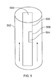
- FIG. 5 illustrates an example downhole tool 500 that can be used to implement any of the examples disclosed herein.
- the downhole tool 500 is positioned within a borehole 502 and includes a thermal sensor 504 positioned on and/or adjacent an exterior surface 506 of the downhole tool 500.
- the thermal sensor 504 may be exposed to fluid within the borehole 502 to determine properties of the fluid.
- the thermal sensor 504 may include a temperature sensor such as the temperature sensor 430 and/or a heater such as the heater 432.
- Equation 1 shows a linear approximating relationship of density, ⁇ , as a function of temperature, T, that may apply to fluids such as aqueous solutions, oils and/or gasses encountered in oilfield applications.
- T f is a reference temperature of the downhole fluid
- ⁇ f is the density of the fluid at the temperature
- T f is the thermal volume expansion coefficient.
- ⁇ ⁇ f ( 1 - ⁇ T - T f
- Equation 1 describes a realistic model for the behavior of a stagnant fluid.
- stagnant fluids may be modeled by other models and equations, which can be used to implement the examples disclosed herein.
- the downhole fluid may be considered as a Boussinecq flow.
- Equation 2 shows the rate of heat transfer from the surface 508 of the thermal sensor 504 to the fluid, in the dimensionless form
- Nu represented by Equation 3
- Ra represented by Equation 4
- Pr represented by Equation 5
- S is the surface 508 of the thermal sensor 504 (e.g., m 2 ) acting as a heater
- P the power for heating the fluid
- ⁇ T temperature excursion
- k the fluid thermal conductivity
- ⁇ is the dynamic viscosity and c p is the fluid specific heat.
- ⁇ is the thermal expansion coefficient
- L is the characteristic size of the heated surface
- g is the acceleration due to gravity
- ⁇ is the thermal diffusivity
- ⁇ is the kinematic viscosity.
- Equation 8 shows an analytical two-dimensional similarity solution for a vertical isothermal wall when the fluid is in natural convection
- A is a function of a Prandl number
- Ra is a Rayleigh number.
- the model on which this similarity solution is based may be appropriate for modeling a situation where the collection chamber, the flowline and/or the borehole containing the fluid is relatively larger than the heater (e.g., the thermal sensor 504, the surface 508).
- the heater e.g., the thermal sensor 504, the surface 508
- other models may be used to determine other similarity solutions that can be used to implement the examples disclosed herein.
- Equation 8 can be used to illustrate the differences in power consumption in various fluids (e.g., water, oil, air, gas) when the surface 508 is kept at a predefined temperature excursion, ⁇ T , over the temperature of the bulk fluid.
- Nu ARa 1 / 4
- Table 1 shows properties for some fluids at 23°C such as dry air, engine oil and ordinary water.
- ⁇ is the part of the Rayleigh number depending from the properties of the fluid and A is a function of the Prandt number.
- Equation 9 defines a ratio of dissipated power for a given temperature excursion, ⁇ T .
- the dissipated amount of power for each type of downhole fluid is determined using Equation 3 relative to the rate of heat transfer and Equation 8. Therefore, in this example, the ratio of power (P 1 and P 2 ) dissipated in fluids 1 and 2 by a predetermined heater and for a predetermined temperature excursion, is given by Equation 9.
- P 1 P 2 k 1 k 2 A 1 A 2 ⁇ 2 ⁇ 2
- the theoretical values P ⁇ , P w , and P ⁇ for a given temperature excursion, ⁇ T, for a fluid of a given composition may be used to compare the measured value of the dissipated amount of power into the fluid to identify the composition or the type of the fluid.
- the theoretical values P ⁇ , P w and P ⁇ are calculated using properties of the respective fluids.
- the thermal sensor 504 measures the value of the dissipated amount of power.
- the temperature excursion may be determined by measuring the temperature of the thermal sensor 504 corresponding to the second temperature, and by measuring the temperature at the sensor 430 remote from the heater 432 corresponding to the first temperature.
- the first temperature can be determined by measuring the temperature at the heater 432 before providing power to the heater 432 (e.g., corresponding to the temperature of the fluid).
- a value of a magnitude, P/ ⁇ T is calculated using the parameters obtained from the thermal sensor 504, the heater 432 and/or the sensor 430 and compared to characteristic values of this magnitude stored in a look-up database or table for different types of fluids (e.g. water, oil, air).
- the fluid composition can be identified using the above-mentioned example method and/or equations.
- heat transfer between the heated surface at temperature T heater (corresponding to the second temperature measured by the sensor 432) and the fluid at temperature T fluid (corresponding to the first temperature measured by the sensor 430) is governed by the Newton's law of cooling.
- the heat dissipation into the fluid is proportional to the temperature excursion, as is shown by Equation 10 below, in which Q is the rate of heat dissipation into the fluid, S is the surface of the sensor and h is the heat transfer coefficient.
- the heat transfer coefficient depends on the flow geometry, the fluid properties and the fluid velocity where the flow geometry is known and the velocity may be measured.
- a magnitude, P/ ⁇ T may be determined by, for example, either choosing ⁇ T constant and measuring variation of P or by choosing P constant and measuring variations of ⁇ T.
- Q depends on P even if P includes the back leakage (portion of the energy wasted to heat the sensor body), which depends on the properties of the sensor. Therefore, the magnitude, P/ ⁇ T, is a function of the known sensor properties; the known flow geometry; the fluid velocity; and the fluid properties.
- the fluid velocity may be determined using an appropriate sensor such as an ultrasonic or electromagnetic velocity sensor.
- the measured value of the magnitude of the power provided to the heater 432 and/or the thermal sensor 504 and/or the temperature excursion can be compared with a value stored in a database for each type or composition of fluid to identify the type of composition of fluid based on the comparison.
- the database stores different values of the magnitude for different fluids or different velocities and/or stores an expression of the magnitude for each fluid as a function of the velocity.
- the reference values may be compared to the measured values to determine the composition of the measured fluid. For example, the characteristic value of the magnitude for each type of fluid being calculated for the measured velocity before may be compared to the measured value of the magnitude.
- FIG. 6 illustrates a portion of an example downhole tool 600 that may be used to implement any of the examples disclosed herein.
- the downhole tool 600 includes the thermal sensor 504 positioned within and/or adjacent a flowline 602.
- the thermal sensor 504 may be used to identify the fluid within the flowline 602 drawn from the formation and/or a borehole in which the downhole tool 600 is positioned.
- the thermal sensor 504 measures the fluid in the flowline 602
- the fluid may be moving (e.g., non-zero velocity) or the fluid may not be moving (e.g., zero velocity).
- FIG. 7 illustrates a portion ,of an example downhole tool 700 that may be used to implement any of the examples disclosed herein.
- the downhole tool 700 includes the thermal sensor 504 positioned within and/or adjacent a chamber 702.
- the thermal sensor 504 may be used to determine properties of the fluid within the chamber 702.
- the fluid within the chamber 702 may be obtained by drawing fluid from the formation and/or a borehole in which the downhole tool 700 is positioned.
- FIG. 8 shows a graph 800 of natural convection occurring near a linear vertical isothermal wall when using a heater in a stagnant fluid where arrows 802, 804 represent the flow of the fluid relative to a heated wall 806.
- FIG. 9 shows a graph 900 of results of placing a thermal sensor in various stagnant fluids one after another where the x-axis 902 corresponds to / time and the y-axis 904 corresponds to Power, P , over a temperature difference, ⁇ T .
- the temperature difference is the difference in the temperature between the temperature of the heated surface 508, 806 and the bulk fluid temperature.
- the thermal sensor was placed in water, then air, then oil and then water again.
- the results of placing the thermal sensor in the water prior to being exposed to oil (e.g., uncontaminated water) and then after being exposed to oil (e.g., contaminated water) are approximately the same.
- the measurements obtained by the thermal sensor remains substantially constant even if the thermal sensor is repeatedly exposed to different fluid types (e.g., oil, water, etc.).
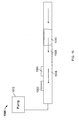
- FIG. 10 illustrates a portion of an example downhole tool 1000 that may be used to implement the examples disclosed herein when fluid has a non-negligible velocity.
- FIG. 11 shows results obtained using the example downhole tool 1000 of FIG. 10 .
- the downhole tool 1000 includes a first thermal sensor 1002 and a second thermal sensor 1004 positioned within and/or adjacent a flowline 1006.
- the thermal sensors 1002, 1004 each include a heater and a temperature sensor.
- the flowline 1006 is filled with water 1008 and an oil slug 1010.
- the fluid velocity is initially zero as represented by reference number 1102 of FIG. 11 .
- the mean fluid velocity is approximately 9 centimeters / second, as represented by reference number 1104 of FIG. 11 .
- the oil slug 1010 passes the second thermal sensor 1004 after approximately 425 seconds and, thereafter, passes the first thermal sensor 1002 as represented by reference number 1106.
- the magnitude P/ ⁇ T determined in view of the measurements taken by the sensor(s) 1002, 1004 decreases as represented by reference number 1108 of FIG. 11 .
- Equation 10 When the velocity of the fluid is caused by the pump 1012, the heat transfer between the heated surface of the sensors 1002, 1004 at temperature, T heater , is governed by Newton's law of cooling where the heat dissipated into the fluid is proportional to the temperature excursion represented by Equation 10, where, Q is the rate of heat dissipation into the fluid, [W] and k is the heat transfer coefficient, [W/m 2 K]. As shown in Equation 11, the heat transfer coefficient is a function of the thermo-physical properties of the fluid (e.g., thermal conductivity, viscosity, etc.) and the mean fluid velocity.
- Equation 10 the heat transfer coefficient is a function of the thermo-physical properties of the fluid (e.g., thermal conductivity, viscosity, etc.) and the mean fluid velocity.
- the fluid type can be identified by measuring h and comparing the result against the values in a look-up table or in a database.
- the sensors 1002, 1004 instead of measuring the heat dissipated into the fluid, the sensors 1002, 1004 measure the power consumption, P , which includes the back leakage (portion of energy wasted to heat the sensor body).
- the sensor window, S remains constant and the shape of the flow conduit remains constant.
- the relationship between power consumption and the temperature difference is a function of the fluid properties and the fluid density.
- V P T heater - T fluid f fluidproperties V
- FIGS. 12 and 13 While an example manner of implementing the coiled tubing system 100 of FIG. 1 , the apparatus 300 of FIG. 3 , the wireline tool 400 of FIG. 4 and/or the downhole tools 500, 600, 700 and 1000 of FIGS. 5 - 7 and 10 are illustrated in FIGS. 12 and 13 , one or more of the elements, processes and/or devices illustrated in FIGS. 12 and 13 may be combined, divided, re-arranged, omitted, eliminated and/or implemented in any other way. Further, one or more aspects of the coiled tubing system 100 of FIG. 1 , the apparatus 300 of FIG. 3 , the wireline tool 400 of FIG. 4 and/or the downhole tools 500, 600, 700 and 1000 of FIGS.
- 5 - 7 and 10 may be implemented by hardware, software, firmware and/or any combination of hardware, software and/or firmware.
- one or more aspects of the coiled tubing system 100 of FIG. 1 , the apparatus 300 of FIG. 3 , the wireline tool 400 of FIG. 4 and/or the downhole tools 500, 600, 700 and 1000 of FIGS. 5 - 7 and 10 could be implemented by one or more analog or digital circuit(s), logic circuits, programmable processor(s), application specific integrated circuit(s) (ASIC(s)), programmable logic device(s) (PLD(s)) and/or field programmable logic device(s) (FPLD(s)).
- ASIC application specific integrated circuit
- PLD programmable logic device
- FPLD field programmable logic device
- At least one or more aspects of the coiled tubing system 100 of FIG. 1 , the apparatus 300 of FIG. 3 , the wireline tool 400 of FIG. 4 and/or the downhole tools 500, 600, 700 and 1000 of FIGS. 5 - 7 and 10 is/are hereby expressly defined to include a tangible computer readable storage device or storage disk such as a memory, a digital versatile disk (DVD), a compact disk (CD), a Blu-ray disk, etc. storing the software and/or firmware.
- a tangible computer readable storage device or storage disk such as a memory, a digital versatile disk (DVD), a compact disk (CD), a Blu-ray disk, etc.
- the downhole tools 500, 600, 700 and 1000 of FIGS. 5 - 7 and 10 may include one or more elements, processes and/or devices in addition to, or instead of, those illustrated in FIGS. 12 and 13 , and/or may include more than one of any or all of the illustrated elements, processes and devices.
- FIGS. 12 and 13 A flowchart representative of example methods for implementing the coiled tubing system 100 of FIG. 1 , the apparatus 300 of FIG. 3 , the wireline tool 400 of FIG. 4 and/or the downhole tools 500, 600, 700 and 1000 of FIGS. 5 - 7 and 10 are shown in FIGS. 12 and 13 .
- the methods may be implemented using machine readable instructions that comprise a program for execution by a processor such as the processor 1412 shown in the example processor platform 1400 discussed below in connection with FIG. 14 .
- the program may be embodied in software stored on a tangible computer readable storage medium such as a CD-ROM, a floppy disk, a hard drive, a digital versatile disk (DVD), a Blu-ray disk, or a memory associated with the processor 1412, but the entire program and/or parts thereof could alternatively be executed by a device other than the processor 1412 and/or embodied in firmware or dedicated hardware.
- a tangible computer readable storage medium such as a CD-ROM, a floppy disk, a hard drive, a digital versatile disk (DVD), a Blu-ray disk, or a memory associated with the processor 1412, but the entire program and/or parts thereof could alternatively be executed by a device other than the processor 1412 and/or embodied in firmware or dedicated hardware.
- FIGS. 12 and 13 many other methods of implementing the coiled tubing system 100 of FIG. 1 , the apparatus 300 of FIG. 3 , the wireline tool 400 of FIG. 4 and/or the downhole tools 500, 600, 700 and
- FIGS. 12 and 13 may be implemented using coded instructions (e.g., computer and/or machine readable instructions) stored on a tangible computer readable storage medium such as a hard disk drive, a flash memory, a read-only memory (ROM), a compact disk (CD), a digital versatile disk (DVD), a cache, a random-access memory (RAM) and/or any other storage device or storage disk in which information is stored for any duration (e.g., for extended time periods, permanently, for brief instances, for temporarily buffering, and/or for caching of the information).
- a tangible computer readable storage medium such as a hard disk drive, a flash memory, a read-only memory (ROM), a compact disk (CD), a digital versatile disk (DVD), a cache, a random-access memory (RAM) and/or any other storage device or storage disk in which information is stored for any duration (e.g., for extended time periods, permanently, for brief instances, for temporarily buffering, and/or for caching of the information).
- tangible computer readable storage medium and “tangible machine readable storage medium” are used interchangeably. Additionally or alternatively, the example methods of FIGS. 12 and 13 may be implemented using coded instructions (e.g., computer and/or machine readable instructions) stored on a non-transitory computer and/or machine readable medium such as a hard disk drive, a flash memory, a read-only memory, a compact disk, a digital versatile disk, a cache, a random-access memory and/or any other storage device or storage disk in which information is stored for any duration (e.g., for extended time periods, permanently, for brief instances, for temporarily buffering, and/or for caching of the information).
- coded instructions e.g., computer and/or machine readable instructions
- a non-transitory computer and/or machine readable medium such as a hard disk drive, a flash memory, a read-only memory, a compact disk, a digital versatile disk, a cache, a random-access memory and/or any other storage device or storage disk in
- non-transitory computer readable medium is expressly defined to include any type of computer readable storage device and/or storage disk and to exclude propagating signals and transmission media.
- phrase “at least” is used as the transition term in a preamble of a claim, it is open-ended in the same manner as the term “comprising" is open ended.
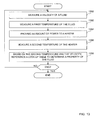
- the example method of FIG. 12 begins by measuring a first temperature at the surface of a heater using the temperature sensor 432 or at another location remote from the heater using the temperature sensor 430 (block 1202). If the sensor is remote from the heater, the sensor 430 may be chosen so that it is in the vicinity of the first location but not influenced by the heater.
- the fluid is a wellbore fluid and/or formation fluid within the coiled tubing system 100, the apparatus 300, the wireline tool 400, the downhole tools 500, 600, 700 and 1000 of FIGS.
- the fluid collecting chamber 426 and/or 428, the flowline 602 and/or the chamber 702 and, thus, the temperature sensor 430 and/or the thermal sensor 504 are positioned within the coiled tubing system 100, the apparatus 300, the wireline tool 400 and/or the downhole tools 500, 600, 700 and 1000 of FIGS. 5 - 7 and 10 adjacent, for example, the fluid collecting chamber 426 and/or 428, the flowline 602 and/or the chamber 702.
- the fluid is a fluid within the borehole 211, 402 and, thus, the temperature sensor 430 and/or the thermal sensor 504 are positioned on and/or adjacent an exterior surface of the coiled tubing system 100, the apparatus 300, the wireline tool 400 and/or the downhole tools 500, 600, 700 and 1000 of FIGS. 5 - 7 and 10 .
- Power may be provided to the heater 432 and/or the thermal sensor 504 to maintain the surface of the heater 432 and/or the thermal sensor 504 at a predefined second temperature greater than the first temperature (block 1204).
- the difference between the first and second temperatures is approximately ten degrees (e.g., +/- 3 degrees and/or units).
- the difference between the first and second temperatures may be any suitable temperature difference (e.g., 5-degrees, 13-degrees, 22-degrees, 27-degrees, etc.).
- the example control unit 136, a logging and control system 252 and/or the electronics and processing system 406 may be used to monitor an amount of power consumed by the heater 432 and/or the thermal sensor 504 to maintain the heater at the second temperature (block 1206). If more heat dissipates from the temperature sensor 430 and/or the thermal sensor 504, the amount of power consumed by the temperature sensor 430 and/or the thermal sensor 504 is higher to maintain the temperature sensor 430 and/or the thermal sensor 504 at the second temperature.
- the example control unit 136 may reference a look-up table and/or a database to compare a magnitude obtained from the amount of power dissipated P and/or the temperature excursion ⁇ T (block 1208) to characteristic values of this magnitude for reference fluids and identify the type or composition of the fluid.
- the logging and control system 252 and the electronic and processing system 406 may use the value of the amount of power consumed by the thermal sensor 504, to differentiate between the fluid being a gas, an oil-based fluid or a water-based fluid.
- the example method of FIG. 13 begins by determining a velocity of the fluid (block 1301).
- the velocity may be determined using a sensor.
- WO 2012/174078 which is hereby incorporated herein by reference in its entirety, describes an exemplary process of determining velocity of the fluid. Other methods and sensors for determining the velocity of a fluid may of course be used.
- the method measures a temperature at the surface of a heater using the temperature sensor 432 or at another location remote from the heater using the temperature sensor 430 (blocks 1302).
- the sensor 430 may be positioned so that it is in the vicinity of the first location but not influenced by the heater.
- the fluid is a wellbore fluid and/or a formation fluid within the coiled tubing system 100, the apparatus 300, the wireline tool 400, the downhole tools 500, 600, 700 and/or 1000, the fluid collecting chamber 426 and/or 428, the flowline 602 and/or the chamber 702 and, thus, the temperature sensor 430 and/or the thermal sensor 504 are positioned within the apparatus 300, the wireline tool 400 and/or the downhole tool 500, 600, 700 and/or 1000 adjacent, for example, the fluid collecting chamber 426 and/or 428, the flowline 602 and/or the chamber 702.
- the fluid is a fluid within the borehole 211, 502 and, thus, the temperature sensor 430 and/or the thermal sensor 504 are positioned on and/or adjacent an exterior surface of the coiled tubing system 100, the apparatus 300, the wireline tool 400 and/or the downhole tool 500, 600, 700 and/or 1000.
- a substantially constant amount of power may be provided to the heater 432 and/or the thermal sensor 504 (block 1304).
- a substantially constant amount of power and a substantially constant amount of power means between about +/- 50 milliWatts and/or +/-5% of a particular wattage).
- different amounts of heat may dissipate from the heater 432 and/or the thermal sensor 504 into the fluid. For example, if the fluid is water, more heat will dissipate into the fluid than if the fluid is a gas.
- control unit 136, the logging and control system 252 and/or the electronics and processing system 406 may be used to monitor a temperature of the heater 432 and/or the thermal sensor 504 (block 1306).
- a temperature excursion in view of the monitored temperature at the second location may be determined and the control unit 136, the logging and control system 252 and/or the electronics and processing system 406 may reference a look-up table and/or a database to compare a magnitude obtained from the amount of power dissipated P and/or the temperature excursion ⁇ T and/or the measured velocity to characteristic values of this magnitude for reference fluids and identify the type or composition of the fluid (block 1308).
- the characteristic values of the magnitude for the reference fluids are calculated as a function of the measured velocity of the fluid.
- FIG. 14 is a block diagram of an example processor platform 1400 capable of executing the instructions to implement the methods of FIG. 12 and 13 and one or more aspects of the apparatus 300 of FIG. 3 , the wireline tool 400 of FIG. 4 and/or downhole tools 500, 600 and 700 of FIGS. 5-7 .
- the processor platform 1400 can be, for example, a server, a personal computer, a mobile device (e.g., a cell phone, a smart phone, a tablet such as an iPad TM ), a personal digital assistant (PDA), an Internet appliance, or any other type of computing device.
- a mobile device e.g., a cell phone, a smart phone, a tablet such as an iPad TM
- PDA personal digital assistant
- the processor platform 1400 of the illustrated example includes a processor 1412.
- the processor 1412 of the illustrated example is hardware.
- the processor 1412 can be implemented by one or more integrated circuits, logic circuits, microprocessors or controllers from any desired family or manufacturer.
- the processor 1412 of the illustrated example includes a local memory 1413 (e.g., a cache).
- the processor 1412 of the illustrated example is in communication with a main memory including a volatile memory 1414 and a non-volatile memory 1416 via a bus 1418.
- the volatile memory 1414 may be implemented by Synchronous Dynamic Random Access Memory (SDRAM), Dynamic Random Access Memory (DRAM), RAMBUS Dynamic Random Access Memory (RDRAM) and/or any other type of random access memory device.
- the non-volatile memory 1416 may be implemented by flash memory and/or any other desired type of memory device. Access to the main memory 1414, 1416 is controlled by a memory controller.
- the processor platform 1400 of the illustrated example also includes an interface circuit 1420.
- the interface circuit 1420 may be implemented by any type of interface standard, such as an Ethernet interface, a universal serial bus (USB), and/or a PCI express interface.
- one or more input devices 1422 are connected to the interface circuit 1420.
- the input device(s) 1422 permit(s) a user to enter data and commands into the processor 1412.
- the input device(s) can be implemented by, for example, an audio sensor, a microphone, a camera (still or video), a keyboard, a button, a mouse, a touchscreen, a track-pad, a trackball, and/or a voice recognition system.
- One or more output devices 1424 are also connected to the interface circuit 1420 of the illustrated example.
- the output devices 1424 can be implemented, for example, by display devices (e.g., a light emitting diode (LED), an organic light emitting diode (OLED), a liquid crystal display, a cathode ray tube display (CRT), a touchscreen, a tactile output device, a light emitting diode (LED), a printer and/or speakers).
- the interface circuit 1420 of the illustrated example thus, typically includes a graphics driver card, a graphics driver chip or a graphics driver processor.
- the interface circuit 1420 of the illustrated example also includes a communication device such as a transmitter, a receiver, a transceiver, a modem and/or network interface card to facilitate exchange of data with external machines (e.g., computing devices of any kind) via a network 1426 (e.g., an Ethernet connection, a digital subscriber line (DSL), a telephone line, coaxial cable, a cellular telephone system, etc.).
- a communication device such as a transmitter, a receiver, a transceiver, a modem and/or network interface card to facilitate exchange of data with external machines (e.g., computing devices of any kind) via a network 1426 (e.g., an Ethernet connection, a digital subscriber line (DSL), a telephone line, coaxial cable, a cellular telephone system, etc.).
- DSL digital subscriber line
- the processor platform 1400 of the illustrated example also includes one or more mass storage devices 1428 for storing software and/or data.
- mass storage devices 1428 include floppy disk drives, hard drive disks, compact disk drives, Blu-ray disk drives, RAID systems, and digital versatile disk (DVD) drives.
- Coded instructions 1432 to implement the methods of FIGS. 12 and 13 may be stored in the mass storage device 1428, in the volatile memory 1414, in the non-volatile memory 1416, and/or on a removable tangible computer readable storage medium such as a CD or DVD.
- a property of a fluid within a chamber, a flowline, borehole, etc. can be determined by measuring the fluid temperature using a temperature sensor and determining an amount of power consumed by the heater to maintain the heater at a predetermined temperature above the measured temperature of fluid. Based on the amount of power consumed, the velocity of the fluid and/or the geometry of the chamber and/or flowline, a processor may reference a look-up table and/or a database to determine if the fluid is an oil-based fluid, a gas or a water-based fluid.
- a substantially constant amount of power is provided to the heater and the temperature of the heater is monitored.
- the processor may reference a look-up table and/or a database to determine if the fluid is an oil-based fluid, a gas or a water-based fluid.
- an example method includes measuring a first temperature of a downhole fluid and providing power to a heater to maintain substantially constant temperature of a surface of a heater exposed to the downhole fluid at a second temperature. The second temperature higher than the first temperature. The method also includes monitoring an amount of power provided to the heater and, based on the amount of power provided, determining a property of the downhole fluid. In some examples, determining the property comprises identifying the downhole fluid as a water-based fluid, an oil-based fluid, or a gas.
- determining the property is further based on a velocity of the downhole fluid.
- the dowhole fluid is within a chamber, a flowline, or a borehole.
- providing the power includes varying the amount of power based on an amount of heat that dissipates into the downhole fluid.
- the amount of power provided to the heater is associated with heat dissipating from the surface into the downhole fluid.
- determining the property of the downhole fluid comprises referencing a look-up table or a database.
- An example method includes measuring a first temperature of a downhole fluid, providing a substantially constant amount of power to a heater to heat a surface of a heater exposed to the downhole fluid and monitoring a second temperature of the surface. The method includes, based on the second temperature of the surface, determining a property of the downhole fluid. In some examples, determining the property includes identifying the downhole fluid as a water-based fluid, an oil-based fluid, or a gas. In some examples, determining the property is further based on the velocity of the downhole fluid. In some examples, the dowhole fluid is within a chamber, a flowline, or a borehole. In some examples, the temperature of the surface is based on heat dissipating into the downhole fluid. In some examples, determining the property comprises referencing a look-up table or a database.
- An example apparatus includes a downhole tool and a first sensor and a second sensor.
- the first and second sensors are to be exposed to a downhole fluid.
- the apparatus includes a processor to cause the first sensor to measure a first temperature of the downhole fluid. Based on the first temperature, the processor is to maintain a temperature of a surface of the second sensor exposed to the downhole fluid at a second temperature.
- the processor is to monitor an amount of power provided to the second sensor to substantially maintain the temperature of the surface at the second temperature, and based on the amount of power provided, the processor to determine a property of the downhole fluid.
- the processor is to reference a look-up table or a database to determine the property of the downhole fluid.
- the first sensor and the second sensor are positioned adjacent a flowline of the downhole tool, the downhole fluid to be within the flowline.
- the first sensor and the second sensor are positioned adjacent a chamber of the downhole tool where he downhole fluid to be within the chamber.
- the first sensor and the second sensor are positioned adjacent an exterior surface of the downhole tool, the downhole fluid to be within the chamber.
- the first sensor and the second sensor are the same sensor.
- the first sensor and the second sensor are part of a single sensor module (RTD sensor).
- the first sensor and the second sensor are immediately adjacent one another.
- the first sensor and the second sensor are spaced apart from one another.
- An example apparatus includes a first sensor and a second sensor where the first and second sensors to be exposed to a downhole fluid.
- the apparatus includes a processor to cause the first sensor to measure a first temperature of the downhole fluid and, based on the first temperature, to provide a substantially constant amount of power to the second sensor to heat a surface of the second sensor exposed to the downhole fluid.
- the processor is to monitor a second temperature of the surface and, based on the second temperature, the processor to determine a property of the downhole fluid.
- the processor is to reference a look-up table or a database to determine the property of the downhole fluid.
- the first sensor and the second sensor are the same sensor.
- the first sensor and the second sensor are part of a single sensor module (RTD sensor).
- the first sensor and the second sensor are immediately adjacent one another.
- the first sensor and the second sensor are spaced apart from one another.
Abstract
Description
- This disclosure relates generally to hydrocarbon production and exploration and, more particularly, to methods and apparatus to determine downhole fluid parameters.
- During hydrocarbon production and/or exploration, it may be advantageous to know the properties of the fluids downhole. Some fluid properties include viscosity, density, composition, etc.
- An example method includes measuring a first temperature of a downhole fluid and providing power to a heater comprising a surface exposed to the downhole fluid to heat the surface to a second temperature. The second temperature higher than the first temperature. The example method also includes monitoring the following parameters:an amount of power provided to the heater; and a temperature excursion between the first and second temperatures. The example method includes, based on at least one of these parameters, identifying a composition of the downhole fluid.
- An example apparatus, comprising a downhole tool; at least a sensor to , be exposed to a downhole fluid and a processor to cause the or one of the sensors to measure a first temperature of the downhole fluid and, to heat a surface of the or one of the sensors exposed to the downhole fluid to a second temperature. The processor to monitor an amount of power provided to the heating sensor and a temperature excursion between the first and second temperatures, and based on at least one of the amount of power provided or the temperature excursion, the processor to identify a composition of the downhole fluid.
-
-
FIG. 1 illustrates an example system in which embodiments of the methods and apparatus to determine downhole fluid parameters can be implemented. -
FIG. 2 illustrates an example system in which embodiments of the methods and apparatus to determine downhole fluid parameters can be implemented. -
FIG. 3 illustrates an example system in which embodiments of the methods and apparatus to determine downhole fluid parameters can be implemented. -
FIG. 4 illustrates an example system in which embodiments of the methods and apparatus to determine downhole fluid parameters can be implemented. -
FIG. 5 illustrates an example system in which embodiments of the methods and apparatus to determine downhole fluid parameters can be implemented. -
FIG. 6 illustrates an example system in which embodiments of the methods and apparatus to determine downhole fluid parameters can be implemented. -
FIG. 7 illustrates an example system in which embodiments of the methods and apparatus to determine downhole fluid parameters can be implemented. -
FIG. 8 shows a graph of natural convection near a vertical isothermal wall generated based on the examples disclosed herein. -
FIG. 9 shows results obtained using the examples disclosed herein. -
FIG.10 illustrates an example system in which embodiments of the methods and apparatus to determine downhole fluid parameters can be implemented. -
FIG. 11 shows results obtained using the examples disclosed herein. -
FIGS. 12 and13 are example processes that can be implemented using the methods and apparatus to determine downhole fluid parameters. -
FIG. 14 is a schematic illustration of an example processor platform that may be used and/or programmed to implement any or all of the example methods and apparatus described herein. - The figures are not to scale. Wherever possible, the same reference numbers will be used throughout the drawing(s) and accompanying written description to refer to the same or like parts.
- During a well treatment and/or a production operation, it may be advantageous to identify the type of fluid within a wellbore, the downhole tool and/or production system, etc. Using the examples disclosed herein, downhole fluids such as oil, gas and/or water may be differentiated and/or identified by exposing a thermal sensor to a fluid, measuring a temperature of the fluid using the thermal sensor and heating the fluid using the thermal sensor. The methods according to the disclosed examples can be used in connection with a fluid having substantially a zero velocity (also referred to as "stagnant") or with a fluid having a non-negligible velocity. However, the disclosed examples may be used in connection with fluids have any velocity (e.g., zero velocity, non-negligible velocity, non-zero velocity, etc.). According to this disclosure, fluid having a non-negligible velocity may be a fluid in which global movement or convection of the downhole fluid is forced with the help of a pump or other injection or suction device(s). According to this disclosure, stagnant fluid may be fluid in which local movements are induced based on interactions of the fluid with its surroundings.
- In some examples, as the temperature of the fluid adjacent the thermal sensor increases, the fluid thermally expands and its density changes causing gravity driven convection, natural convection and/or buoyancy driven flow. Based on properties of the fluid, the rate of heat transfer between the thermal sensor and the fluid may vary. For example, if the downhole fluid is a gas, a relatively small amount of heat may dissipate from the thermal sensor. If the downhole fluid is an oil, more heat may dissipate from the thermal sensor than if the downhole fluid were a gas. If the downhole fluid is water, more heat may dissipate from the thermal senor than if the downhole fluid were a gas or an oil. The more heat that dissipates from the thermal sensor, the more power is consumed by the thermal sensor to maintain the thermal sensor at a relatively constant and/or substantially constant temperature. As used herein, a substantially constant temperature is within about 5-degrees or units of a given temperature. Additionally, the more heat that dissipates from the thermal sensor, the lower the temperature the thermal sensor will be if a constant amount of power is supplied to the thermal sensor. Thus, based on an amount of power provided to the thermal sensor and/or a temperature of the thermal sensor, properties of the fluid may be determined using the examples disclosed herein.
-
FIG. 1 is a schematic illustration of anexample wellsite 100 including an example coiledtubing system 102 deployed into awell 104 that can be used to implement the examples disclosed herein. The coiledtubing system 102 hassurface delivery equipment 106 including a coiledtubing truck 108 with areel 110. In this example, thesurface delivery equipment 106 is positioned adjacent thewell 104 at thewellsite 100. The example coiledtubing system 102 also includescoiled tubing 114 that may be used to pump fluid into thewell 104. By running thecoiled tubing 114 through agooseneck injector 116, thecoiled tubing 114 may be advanced into thewell 104. That is, thecoiled tubing 114 may be forced down through valving andpressure control equipment 120 and into thewell 104. In this example, thegooseneck injector 116 is supported by amast 118 over thewell 104. - In the example coiled
tubing system 102 ofFIG. 1 , anexample treatment device 122 is provided for delivering fluids downhole during a treatment application. Thetreatment device 122 is deployable into thewell 104 to carry fluids such as, for example, an acidizing agent or other treatment fluid. Theexample treatment device 122 may disperse the fluids through at least one injection port ornozzle 124 of thetreatment device 122 into, for example, the formation. - The coiled
tubing system 102 ofFIG. 1 is depicted as having afluid sensing system 126 positioned about theinjection port 124 for determining parameters of fluids in thewell 104. Alternatively, thefluid sensing system 126 may be positioned within thecoiled tubing 114 for determining parameters of fluids in the coiled tubing 112. Thefluid sensing system 126 is preferably configured to determine fluid parameters, such as the composition of the downhole fluid (e.g., oil, water, gas), the state of the downhole fluid and/or fluid direction and/or velocity. Other downhole parameters (e.g., temperature) may also be determined using thefluid sensing system 126, if desired. In some examples, the examplefluid sensing system 126 determines parameters of the fluid within thewell 104. In some examples, the examplefluid sensing system 126 determines parameters of the fluid within a flowline and/or chamber of the coiledtubing system 102. - In some examples, the coiled
tubing system 102 is optionally provided with alogging tool 128 for collecting downhole data. In this example, thelogging tool 128 is positioned adjacent a downhole end of the coiledtubing 114. Theexample logging tool 128 may be configured to acquire a variety of logging data from the well 104 and surroundingformation layers FIG. 1 . Theexample logging tool 128 may be provided with well profile generating equipment or implements configured for production logging directed at acquiring well fluids and formation measurements from which an overall production profile may be developed. Other logging, data acquisition, monitoring, imaging and/or other devices and/or capabilities may be provided to acquire data relative to a variety of well characteristics. Information gathered may be acquired at the surface in a high speed manner and, where appropriate, put to immediate real-time use (e.g. via a treatment application). - The
coiled tubing 114 ofFIG. 1 including thetreatment device 122, thefluid sensing system 126 and thelogging tool 128 is shown as being deployed downhole. As the coiledtubing 114 and the associated components are deployed downhole, treatment, sensing and/or logging applications may be directed by anexample control unit 136 at the surface. For example, theexample control unit 136 may cause thetreatment device 122 to be activated to release fluid from theinjection port 124; theexample control unit 136 may cause thefluid sensing system 126 to be activated to collect fluid measurements; and/or theexample control unit 136 may cause thelogging tool 128 to be activated to log downhole data, as desired. In some examples, thetreatment device 122, thefluid sensing system 126 and/or thelogging tool 128 communicate with thecontrol unit 136 via a communication link for passing signals (e.g., power, communication, control, etc.) therebetween. - The
example control unit 136 ofFIG. 1 is depicted as computerized equipment secured to atruck 108. However, thecontrol unit 136 may be a laptop computer or any other type of mobile or stationary computing and/or processing device at the wellsite 100 or remote to thewellsite 100. Additionally, thecoiled tubing system 102 may be controlled by hydraulic, pneumatic and/or electrical signals. Regardless, the wireless nature of the communication enables thecontrol unit 136 to control the operation of the coiledtubing system 102, even in circumstances where subsequent different application assemblies may be deployed downhole. That is, in some examples, the need for a subsequent mobilization of control equipment may be eliminated. - The
example control unit 136 may be configured to wirelessly communicate with anexample transceiver hub 138 of thecoiled tubing reel 110. Thetransceiver hub 138 may be configured for communication onsite (surface and/or downhole) and/or offsite as desired. In some examples, thecontrol unit 136 communicates with thesensing system 126 and/or thelogging tool 128 to pass data therebetween. Thecontrol unit 136 may be provided with and/or coupled to databases, processors, and/or communicators for collecting, storing, analyzing, and/or processing data collected from the sensing system and/or logging tool. -
FIG. 2 illustrates a wellsite system in which the examples disclosed herein can be employed. The wellsite can be onshore or offshore. In this example system, aborehole 211 is formed in subsurface formations by rotary drilling. However, the examples disclosed herein can also use directional drilling, for example. - A
drill string 212 is suspended within theborehole 211 and has abottom hole assembly 200 that includes adrill bit 205 at its lower end. The surface system includes a platform andderrick assembly 210 positioned over theborehole 211. Theassembly 210 includes a rotary table 216, akelly 217, ahook 218 and arotary swivel 219. Thedrill string 212 is rotated by the rotary table 216. The rotatory table 216 may be energized by a device or system not shown. The rotary table 216 may engage thekelly 217 at the upper end of thedrill string 212. Thedrill string 212 is suspended from thehook 218, which is attached to a traveling block. Additionally, thedrill string 212 is positioned through thekelly 217 and therotary swivel 219, which permits rotation of thedrill string 212 relative to thehook 218. Additionally or alternatively, a top drive system may be used to impart rotation to thedrill string 212. - In this example, the surface system further includes drilling fluid or
mud 226 stored in apit 227 formed at the well site. Apump 229 delivers thedrilling fluid 226 to the interior of thedrill string 212 via a port in theswivel 219, causing thedrilling fluid 226 to flow downwardly through thedrill string 212 as indicated by thedirectional arrow 208. Thedrilling fluid 226 exits thedrill string 212 via ports in thedrill bit 205, and then circulates upwardly through the annulus region between the outside of thedrill string 212 and the wall of theborehole 211, as indicated by thedirectional arrows 209. In this manner, thedrilling fluid 226 lubricates thedrill bit 205 and carries formation cuttings up to the surface as it is returned to thepit 227 for recirculation. - The
bottom hole assembly 200 of the example illustrated inFIG. 2 includes a logging-while-drilling (LWD)module 220, a measuring-while-drilling (MWD)module 230, a roto-steerable system andmotor 250, and thedrill bit 205. - The
LWD module 220 may be housed in a special type of drill collar and can contain one or more logging tools. In some examples, thebottom hole assembly 200 may include additional LWD and/or MWD modules. As such, references throughout this description to reference numeral 220 may additionally or alternatively include 220A. TheLWD module 220 may include capabilities for measuring, processing, and storing information, as well as for communicating with the surface equipment. Additionally or alternatively, theLWD module 220 includes a sonic measuring device. - The
MWD module 230 may also be housed in a drill collar and can contain one or more devices for measuring characteristics of thedrill string 212 and/ordrill bit 205. TheMWD module 230 may further include an apparatus for generating electrical power for at least portions of thebottom hole assembly 200. The apparatus for generating electrical power may include a mud turbine generator powered by the flow of the drilling fluid. However, other power and/or battery systems may be employed. In this example, theMWD module 230 includes one or more of the following types of measuring devices: a weight-on-bit measuring device, a torque measuring device, a vibration measuring device, a shock measuring device, a stick slip measuring device, a direction measuring device and/or an inclination measuring device. - Although the components of
FIG. 2 are shown and described as being implemented in a particular conveyance type, the examples disclosed herein are not limited to a particular conveyance type but, instead, may be implemented in connection with different conveyance types including, for example, coiled tubing, wireline wired drillpipe and/or any other conveyance types known in the industry. -
FIG. 3 is a simplified diagram of a sampling-while-drilling logging device and/orapparatus 300 of a type described inU.S. Patent 7,114,562 , incorporated herein by reference in its entirety, that can be used to implement theLWD tools FIG. 3 is provided with aprobe 306 for establishing fluid communication with the formation and drawingfluid 321 into the tool, as indicated by the arrows. Theprobe 306 may be positioned, for example, in astabilizer blade 323 of theapparatus 300 and extend therefrom to engage aborehole wall 302. Thestabilizer blade 323 comprises one or more blades that are in contact with theborehole wall 302. - The fluid drawn into the
apparatus 300 using theprobe 306 may be measured to determine, for example, pretest and/or pressure parameters. In some examples, theapparatus 300 may include one or more sensors (e.g., a thermal sensor, a temperature sensor, a heater) that are used to differentiate between and/or identify the composition of downhole fluids. The sensors may be implemented in a single module. Alternatively, the sensors may be implemented by separately-spaced devices. In some examples, one or more of these sensors are positioned adjacent a chamber or flowline of theapparatus 300 to determine properties of the fluid within the chamber or flowline. In other examples, one or more of these sensors may be positioned adjacent an exterior surface of theapparatus 300 to determine properties of the fluid within theborehole 211. Regardless of the position of the one or more sensors, the fluid being analyzed may or may not be moving (e.g., zero-velocity, negligible velocity, non-zero velocity). Additionally or alternatively, theapparatus 300 may be provided with devices, such as sample chambers for collecting fluid samples for retrieval at the surface.Backup pistons 381 may also be provided to assist in applying force to push the drilling tool and/or probe against theborehole wall 302. -
FIG. 4 shows anexample wireline tool 400 that may be another environment in which aspects of the present disclosure may be implemented. Theexample wireline tool 400 is suspended in awellbore 402 from the lower end of amulticonductor cable 404 that is spooled on a winch at the Earth's surface. At the surface, thecable 404 is communicatively coupled to an electronics andprocessing system 406. Theexample wireline tool 400 includes anelongated body 408 that includes aformation tester 414 having a selectivelyextendable probe assembly 416 and a selectively extendabletool anchoring member 418 that are arranged on opposite sides of theelongated body 408. Additional components (e.g., 410) may also be included in thetool 400. - In this example, the
extendable probe assembly 416 is configured to selectively seal off or isolate selected portions of the wall of thewellbore 402 to fluidly couple to the adjacent formation F and/or to draw fluid samples from the formation F. Accordingly, theextendable probe assembly 416 may be provided with a probe having an embedded plate, for example. In the illustrated example, the electronics andprocessing system 406 and/or a downhole control system are configured to control theextendable probe assembly 416 and/or the drawing of a fluid sample from the formation F. The formation fluid may be expelled through a port or it may be sent to first and/or secondfluid collecting chambers - In some examples, a first sensor acting as a heater and/or a
temperature sensor 430 and a second sensor acting as a temperature sensor and/or aheater 432, are positioned within the firstfluid collecting chamber 426 and/or the secondfluid collecting chamber 428. Thetemperature sensor 430 and theheater 432 may be incorporated into a thermal sensor implemented as a single module. In examples in which thesensors fluid collection chamber fluid collection chamber temperature sensor 430 and/or theheater 432 and/or the sensor module may be used to determine a property of the fluid (e.g., gas, water, oil, etc.) and/or a composition of the fluid. For example, based on the temperature of the fluid, a rate of heat dissipated into the fluid, Q, and/or an amount of power, P, consumed by theheater 432 when heating the fluid, the different fluids may be identified. - One or more of the
sensors PCT publication WO2012/000654 , which is hereby incorporated herein by reference in its entirety. - In some examples, when determining a property of the fluid, the
first temperature sensor 430 may measure a first temperature of the fluid and theheater 432 may be provided power, P, to heat theheater 432 to a second temperature greater than the first temperature. Thefirst temperature sensor 430 may measure a first temperature of the fluid before, while and/or after power is provided to theheater 432. A second temperature may be measured at theheater 432. In other examples, theheater 432 and/or another sensor adjacent thereto measures a first temperature before power is provided to theheater 432 and measures a second temperature after power is provided to theheater 432. In such examples, theheater 432 also includes a temperature sensor and may be, for example, a RTD sensor. Depending on properties of the fluid, different amounts of heat may dissipate into the fluid from theheater 432 and/or different amounts of power, P, may be consumed by theheater 432 to maintain theheater 432 at a particular temperature. In some examples, the electronics andprocessing unit 406 monitors an amount of power, P, consumed by theheater 432 to maintain theheater 432 at a particular temperature. In other examples, the electronics andprocessing unit 406 monitors temperature, T, of theheater 432 when being provided a substantially constant or consistent power, P. The amount of power consumed by theheater 432 to maintain theheater 432 at a substantially constant temperature and/or the temperature of theheater 432 after being provided a substantially constant amount of power relates to a rate of heat dissipation of theheater 432. Based on the temperature excursion and/or an amount of power consumed by theheater 432 along with other parameters (e.g., the velocity of the fluid, etc.), the electronics andprocessing system 406 may reference a look-up table and/or a database to compare data and identify the composition, type and/or parameters of the corresponding fluid. In some examples, the electronics andprocessing system 406 compares a magnitude of the values (e.g., a temperature value, a power consumed value, a velocity of the fluid, etc.) obtained by the sensors (e.g., a single thermal sensor, a sensor module, thetemperature sensor 430, the heater 432) to the magnitude of values for reference fluids to identify the composition, parameters and/or other characteristics of the corresponding fluid. For example, the comparison may be used to determine if the fluid is associated with a gas, an oil-based fluid or a water-based fluid. -
FIG. 5 illustrates an exampledownhole tool 500 that can be used to implement any of the examples disclosed herein. In this example, thedownhole tool 500 is positioned within aborehole 502 and includes athermal sensor 504 positioned on and/or adjacent anexterior surface 506 of thedownhole tool 500. Thus, thethermal sensor 504 may be exposed to fluid within theborehole 502 to determine properties of the fluid. Thethermal sensor 504 may include a temperature sensor such as thetemperature sensor 430 and/or a heater such as theheater 432. - In some examples, in particular when the fluid is a stagnant fluid, heating a
surface 508 of thethermal sensor 504 heats the fluid adjacent thereto causing temperature variations within the fluid that induce density variations and buoyancy driven flow.Equation 1 shows a linear approximating relationship of density, ρ, as a function of temperature, T, that may apply to fluids such as aqueous solutions, oils and/or gasses encountered in oilfield applications. Referring toEquation 1, Tf is a reference temperature of the downhole fluid, ρf is the density of the fluid at the temperature, Tf , and β is the thermal volume expansion coefficient.
-
Equation 1 describes a realistic model for the behavior of a stagnant fluid. However, stagnant fluids may be modeled by other models and equations, which can be used to implement the examples disclosed herein. - In some examples, if the maximum relative density difference,

- Equation 2 shows the rate of heat transfer from the
surface 508 of thethermal sensor 504 to the fluid, in the dimensionless form where Nu, represented by Equation 3, is the Nusselt number averaged over thesurface 508, Ra, represented by Equation 4, is the Rayleigh number and Pr, represented byEquation 5, is the Prandtl number. Referring to Equation 3, S is thesurface 508 of the thermal sensor 504 (e.g., m2) acting as a heater, P is the power for heating the fluid, ΔT (temperature excursion) is the difference between the temperature of thesurface 508 corresponding at the second temperature measured atheater 432 and the temperature of the bulk fluid corresponding to the first temperature measured atfirst sensor 430 and k is the fluid thermal conductivity. Referring to Equation 4, µ is the dynamic viscosity and cp is the fluid specific heat. Referring toEquation 5, β is the thermal expansion coefficient, L is the characteristic size of the heated surface, g is the acceleration due to gravity, α is the thermal diffusivity and ν is the kinematic viscosity.


- Equation 6 defines the thermal diffusivity, α, where k is the thermal conductivity and ρ is the density.

- Equation 7 defines the kinematic viscosity, ν, where µ is the dynamic viscosity and ρ is the density.

- Equation 8 shows an analytical two-dimensional similarity solution for a vertical isothermal wall when the fluid is in natural convection where A is a function of a Prandl number and Ra is a Rayleigh number. The model on which this similarity solution is based may be appropriate for modeling a situation where the collection chamber, the flowline and/or the borehole containing the fluid is relatively larger than the heater (e.g., the
thermal sensor 504, the surface 508). However, other models may be used to determine other similarity solutions that can be used to implement the examples disclosed herein. In some examples, Equation 8 can be used to illustrate the differences in power consumption in various fluids (e.g., water, oil, air, gas) when thesurface 508 is kept at a predefined temperature excursion, ΔT, over the temperature of the bulk fluid.
- Table 1 shows properties for some fluids at 23°C such as dry air, engine oil and ordinary water.
Table 1: Fluids at 23 degC Thermal conductivity, k, [W/m] 
Prandt1 number Pr A water 0.590 1.52 1010 7.00 0.601 oil 0.144 1.47 108 6.45 103 0.665 air 0.025 1.07 108 0.72 0.516 - In the table above, θ is the part of the Rayleigh number depending from the properties of the fluid and A is a function of the Prandt number.
-
Equation 9 defines a ratio of dissipated power for a given temperature excursion, ΔT. In this example, the dissipated amount of power for each type of downhole fluid is determined using Equation 3 relative to the rate of heat transfer and Equation 8. Therefore, in this example, the ratio of power (P1 and P2) dissipated influids 1 and 2 by a predetermined heater and for a predetermined temperature excursion, is given byEquation 9.
- Using table 1 and
Equation 9, the following ratios of the power dissipated in a water-based fluid, Pw , an oil-based fluid, Pσ , and air, Pα may be determined.


- The theoretical values Pσ , Pw , and Pα for a given temperature excursion, ΔT, for a fluid of a given composition may be used to compare the measured value of the dissipated amount of power into the fluid to identify the composition or the type of the fluid. In some examples, the theoretical values Pσ, Pw and Pα are calculated using properties of the respective fluids. In some examples, the
thermal sensor 504 measures the value of the dissipated amount of power. In some examples, the temperature excursion may be determined by measuring the temperature of thethermal sensor 504 corresponding to the second temperature, and by measuring the temperature at thesensor 430 remote from theheater 432 corresponding to the first temperature. Alternatively, the first temperature can be determined by measuring the temperature at theheater 432 before providing power to the heater 432 (e.g., corresponding to the temperature of the fluid). - In some examples, for identifying the fluid type or composition when the fluid is stagnant, a value of a magnitude, P/ΔT, is calculated using the parameters obtained from the
thermal sensor 504, theheater 432 and/or thesensor 430 and compared to characteristic values of this magnitude stored in a look-up database or table for different types of fluids (e.g. water, oil, air). - As the response of the
thermal sensor 504 for water is one order of magnitude higher than for oil and two orders of magnitude higher than for air and the response of thethermal sensor 504 for air is one order of magnitude smaller than for oil, the fluid composition can be identified using the above-mentioned example method and/or equations. - In other examples, in particular, when the fluid has a non-negligible velocity, heat transfer between the heated surface at temperature Theater (corresponding to the second temperature measured by the sensor 432) and the fluid at temperature Tfluid (corresponding to the first temperature measured by the sensor 430) is governed by the Newton's law of cooling. The heat dissipation into the fluid is proportional to the temperature excursion, as is shown by
Equation 10 below, in which Q is the rate of heat dissipation into the fluid, S is the surface of the sensor andh is the heat transfer coefficient. The heat transfer coefficient depends on the flow geometry, the fluid properties and the fluid velocity where the flow geometry is known and the velocity may be measured.
- Regardless of the chosen model (zero or non-negligible velocity), a magnitude, P/ΔT, may be determined by, for example, either choosing ΔT constant and measuring variation of P or by choosing P constant and measuring variations of ΔT. As shown, Q depends on P even if P includes the back leakage (portion of the energy wasted to heat the sensor body), which depends on the properties of the sensor. Therefore, the magnitude, P/ΔT, is a function of the known sensor properties; the known flow geometry; the fluid velocity; and the fluid properties. The fluid velocity may be determined using an appropriate sensor such as an ultrasonic or electromagnetic velocity sensor.
- As explained in the first examples, the measured value of the magnitude of the power provided to the
heater 432 and/or thethermal sensor 504 and/or the temperature excursion can be compared with a value stored in a database for each type or composition of fluid to identify the type of composition of fluid based on the comparison. In some examples, the database stores different values of the magnitude for different fluids or different velocities and/or stores an expression of the magnitude for each fluid as a function of the velocity. The reference values may be compared to the measured values to determine the composition of the measured fluid. For example, the characteristic value of the magnitude for each type of fluid being calculated for the measured velocity before may be compared to the measured value of the magnitude. -
FIG. 6 illustrates a portion of an exampledownhole tool 600 that may be used to implement any of the examples disclosed herein. In this example, thedownhole tool 600 includes thethermal sensor 504 positioned within and/or adjacent aflowline 602. Thus, thethermal sensor 504 may be used to identify the fluid within theflowline 602 drawn from the formation and/or a borehole in which thedownhole tool 600 is positioned. When thethermal sensor 504 measures the fluid in theflowline 602, the fluid may be moving (e.g., non-zero velocity) or the fluid may not be moving (e.g., zero velocity). -
FIG. 7 illustrates a portion ,of an exampledownhole tool 700 that may be used to implement any of the examples disclosed herein. In this example, thedownhole tool 700 includes thethermal sensor 504 positioned within and/or adjacent achamber 702. Thus, thethermal sensor 504 may be used to determine properties of the fluid within thechamber 702. The fluid within thechamber 702 may be obtained by drawing fluid from the formation and/or a borehole in which thedownhole tool 700 is positioned. -
FIG. 8 shows agraph 800 of natural convection occurring near a linear vertical isothermal wall when using a heater in a stagnant fluid wherearrows heated wall 806. -
FIG. 9 shows agraph 900 of results of placing a thermal sensor in various stagnant fluids one after another where thex-axis 902 corresponds to / time and the y-axis 904 corresponds to Power, P, over a temperature difference, ΔT. In this example, the temperature difference is the difference in the temperature between the temperature of theheated surface -
FIG. 10 illustrates a portion of an exampledownhole tool 1000 that may be used to implement the examples disclosed herein when fluid has a non-negligible velocity.FIG. 11 shows results obtained using the exampledownhole tool 1000 ofFIG. 10 . In this example, thedownhole tool 1000 includes a firstthermal sensor 1002 and a secondthermal sensor 1004 positioned within and/or adjacent aflowline 1006. In this example, thethermal sensors flowline 1006 is filled withwater 1008 and anoil slug 1010. In this example, the fluid velocity is initially zero as represented byreference number 1102 ofFIG. 11 . When pumping begins using apump 1012, the mean fluid velocity is approximately 9 centimeters / second, as represented byreference number 1104 ofFIG. 11 . As shown inFIG. 11 , theoil slug 1010 passes the secondthermal sensor 1004 after approximately 425 seconds and, thereafter, passes the firstthermal sensor 1002 as represented byreference number 1106. When theoil slug 1010 passes thesensors reference number 1108 ofFIG. 11 . - When the velocity of the fluid is caused by the
pump 1012, the heat transfer between the heated surface of thesensors Equation 10, where, Q is the rate of heat dissipation into the fluid, [W] andk is the heat transfer coefficient, [W/m2 K]. As shown in Equation 11, the heat transfer coefficient is a function of the thermo-physical properties of the fluid (e.g., thermal conductivity, viscosity, etc.) and the mean fluid velocity. Thus, if the fluid velocity is known, the fluid type can be identified by measuringh and comparing the result against the values in a look-up table or in a database. In practice and as represented by Equation 12, instead of measuring the heat dissipated into the fluid, thesensors 


- While an example manner of implementing the
coiled tubing system 100 ofFIG. 1 , theapparatus 300 ofFIG. 3 , thewireline tool 400 ofFIG. 4 and/or thedownhole tools FIGS. 5 - 7 and10 are illustrated inFIGS. 12 and13 , one or more of the elements, processes and/or devices illustrated inFIGS. 12 and13 may be combined, divided, re-arranged, omitted, eliminated and/or implemented in any other way. Further, one or more aspects of the coiledtubing system 100 ofFIG. 1 , theapparatus 300 ofFIG. 3 , thewireline tool 400 ofFIG. 4 and/or thedownhole tools FIGS. 5 - 7 and10 may be implemented by hardware, software, firmware and/or any combination of hardware, software and/or firmware. Thus, for example, one or more aspects of the coiledtubing system 100 ofFIG. 1 , theapparatus 300 ofFIG. 3 , thewireline tool 400 ofFIG. 4 and/or thedownhole tools FIGS. 5 - 7 and10 could be implemented by one or more analog or digital circuit(s), logic circuits, programmable processor(s), application specific integrated circuit(s) (ASIC(s)), programmable logic device(s) (PLD(s)) and/or field programmable logic device(s) (FPLD(s)). When reading any of the apparatus or system claims of this patent to cover a purely software and/or firmware implementation, at least one or more aspects of the coiledtubing system 100 ofFIG. 1 , theapparatus 300 ofFIG. 3 , thewireline tool 400 ofFIG. 4 and/or thedownhole tools FIGS. 5 - 7 and10 is/are hereby expressly defined to include a tangible computer readable storage device or storage disk such as a memory, a digital versatile disk (DVD), a compact disk (CD), a Blu-ray disk, etc. storing the software and/or firmware. Further still, one or more aspects of the coiledtubing system 100 ofFIG. 1 , theapparatus 300 ofFIG. 3 , thewireline tool 400 ofFIG. 4 and/or thedownhole tools FIGS. 5 - 7 and10 may include one or more elements, processes and/or devices in addition to, or instead of, those illustrated inFIGS. 12 and13 , and/or may include more than one of any or all of the illustrated elements, processes and devices. - A flowchart representative of example methods for implementing the
coiled tubing system 100 ofFIG. 1 , theapparatus 300 ofFIG. 3 , thewireline tool 400 ofFIG. 4 and/or thedownhole tools FIGS. 5 - 7 and10 are shown inFIGS. 12 and13 . In this example, the methods may be implemented using machine readable instructions that comprise a program for execution by a processor such as theprocessor 1412 shown in theexample processor platform 1400 discussed below in connection withFIG. 14 . The program may be embodied in software stored on a tangible computer readable storage medium such as a CD-ROM, a floppy disk, a hard drive, a digital versatile disk (DVD), a Blu-ray disk, or a memory associated with theprocessor 1412, but the entire program and/or parts thereof could alternatively be executed by a device other than theprocessor 1412 and/or embodied in firmware or dedicated hardware. Further, although the example program is described with reference to the flowchart illustrated inFIGS. 12 and13 , many other methods of implementing thecoiled tubing system 100 ofFIG. 1 , theapparatus 300 ofFIG. 3 , thewireline tool 400 ofFIG. 4 and/or thedownhole tools FIGS. 5 - 7 and10 may alternatively be used. For example, the order of execution of the blocks may be changed, and/or some of the blocks described may be changed, eliminated, or combined. - As mentioned above, the example methods of
FIGS. 12 and13 may be implemented using coded instructions (e.g., computer and/or machine readable instructions) stored on a tangible computer readable storage medium such as a hard disk drive, a flash memory, a read-only memory (ROM), a compact disk (CD), a digital versatile disk (DVD), a cache, a random-access memory (RAM) and/or any other storage device or storage disk in which information is stored for any duration (e.g., for extended time periods, permanently, for brief instances, for temporarily buffering, and/or for caching of the information). As used herein, the term tangible computer readable storage medium is expressly defined to include any type of computer readable storage device and/or storage disk and to exclude propagating signals and transmission media. As used herein, "tangible computer readable storage medium" and "tangible machine readable storage medium" are used interchangeably. Additionally or alternatively, the example methods ofFIGS. 12 and13 may be implemented using coded instructions (e.g., computer and/or machine readable instructions) stored on a non-transitory computer and/or machine readable medium such as a hard disk drive, a flash memory, a read-only memory, a compact disk, a digital versatile disk, a cache, a random-access memory and/or any other storage device or storage disk in which information is stored for any duration (e.g., for extended time periods, permanently, for brief instances, for temporarily buffering, and/or for caching of the information). As used herein, the term non-transitory computer readable medium is expressly defined to include any type of computer readable storage device and/or storage disk and to exclude propagating signals and transmission media. As used herein, when the phrase "at least" is used as the transition term in a preamble of a claim, it is open-ended in the same manner as the term "comprising" is open ended. - The example method of
FIG. 12 begins by measuring a first temperature at the surface of a heater using thetemperature sensor 432 or at another location remote from the heater using the temperature sensor 430 (block 1202). If the sensor is remote from the heater, thesensor 430 may be chosen so that it is in the vicinity of the first location but not influenced by the heater. In some examples, the fluid is a wellbore fluid and/or formation fluid within the coiledtubing system 100, theapparatus 300, thewireline tool 400, thedownhole tools FIGS. 5 - 7 and10 , thefluid collecting chamber 426 and/or 428, theflowline 602 and/or thechamber 702 and, thus, thetemperature sensor 430 and/or thethermal sensor 504 are positioned within the coiledtubing system 100, theapparatus 300, thewireline tool 400 and/or thedownhole tools FIGS. 5 - 7 and 10 adjacent, for example, thefluid collecting chamber 426 and/or 428, theflowline 602 and/or thechamber 702. In other examples, the fluid is a fluid within theborehole temperature sensor 430 and/or thethermal sensor 504 are positioned on and/or adjacent an exterior surface of the coiledtubing system 100, theapparatus 300, thewireline tool 400 and/or thedownhole tools FIGS. 5 - 7 and10 . - Power may be provided to the
heater 432 and/or thethermal sensor 504 to maintain the surface of theheater 432 and/or thethermal sensor 504 at a predefined second temperature greater than the first temperature (block 1204). In some examples, the difference between the first and second temperatures is approximately ten degrees (e.g., +/- 3 degrees and/or units). However, the difference between the first and second temperatures may be any suitable temperature difference (e.g., 5-degrees, 13-degrees, 22-degrees, 27-degrees, etc.). Atblock 1206, theexample control unit 136, a logging andcontrol system 252 and/or the electronics andprocessing system 406 may be used to monitor an amount of power consumed by theheater 432 and/or thethermal sensor 504 to maintain the heater at the second temperature (block 1206). If more heat dissipates from thetemperature sensor 430 and/or thethermal sensor 504, the amount of power consumed by thetemperature sensor 430 and/or thethermal sensor 504 is higher to maintain thetemperature sensor 430 and/or thethermal sensor 504 at the second temperature. In some examples, based on the amount of power consumed by theheater 432 and/or thethermal sensor 504, theexample control unit 136, the logging andcontrol system 252 and/or the electronics andprocessing system 406 may reference a look-up table and/or a database to compare a magnitude obtained from the amount of power dissipated P and/or the temperature excursion ΔT (block 1208) to characteristic values of this magnitude for reference fluids and identify the type or composition of the fluid. For example, the logging andcontrol system 252 and the electronic andprocessing system 406 may use the value of the amount of power consumed by thethermal sensor 504, to differentiate between the fluid being a gas, an oil-based fluid or a water-based fluid. - The example method of
FIG. 13 begins by determining a velocity of the fluid (block 1301). The velocity may be determined using a sensor.WO 2012/174078 , which is hereby incorporated herein by reference in its entirety, describes an exemplary process of determining velocity of the fluid. Other methods and sensors for determining the velocity of a fluid may of course be used. The method then measures a temperature at the surface of a heater using thetemperature sensor 432 or at another location remote from the heater using the temperature sensor 430 (blocks 1302). Thesensor 430 may be positioned so that it is in the vicinity of the first location but not influenced by the heater. In some examples, the fluid is a wellbore fluid and/or a formation fluid within the coiledtubing system 100, theapparatus 300, thewireline tool 400, thedownhole tools fluid collecting chamber 426 and/or 428, theflowline 602 and/or thechamber 702 and, thus, thetemperature sensor 430 and/or thethermal sensor 504 are positioned within theapparatus 300, thewireline tool 400 and/or thedownhole tool fluid collecting chamber 426 and/or 428, theflowline 602 and/or thechamber 702. In other examples, the fluid is a fluid within theborehole temperature sensor 430 and/or thethermal sensor 504 are positioned on and/or adjacent an exterior surface of the coiledtubing system 100, theapparatus 300, thewireline tool 400 and/or thedownhole tool - A substantially constant amount of power may be provided to the
heater 432 and/or the thermal sensor 504 (block 1304). As used herein, a substantially constant amount of power and a substantially constant amount of power means between about +/- 50 milliWatts and/or +/-5% of a particular wattage). Based on properties of the fluid adjacent thetemperature sensor 430 and/or thethermal sensor 504, if a constant amount of power is provided to theheater 432 and/or thethermal sensor 504, different amounts of heat may dissipate from theheater 432 and/or thethermal sensor 504 into the fluid. For example, if the fluid is water, more heat will dissipate into the fluid than if the fluid is a gas. Atblock 1306, thecontrol unit 136, the logging andcontrol system 252 and/or the electronics andprocessing system 406 may be used to monitor a temperature of theheater 432 and/or the thermal sensor 504 (block 1306). In some examples, based on the temperature of theheater 432 and/or the thermal sensor 504 a temperature excursion in view of the monitored temperature at the second location may be determined and thecontrol unit 136, the logging andcontrol system 252 and/or the electronics andprocessing system 406 may reference a look-up table and/or a database to compare a magnitude obtained from the amount of power dissipated P and/or the temperature excursionΔT and/or the measured velocity to characteristic values of this magnitude for reference fluids and identify the type or composition of the fluid (block 1308). In some examples, the characteristic values of the magnitude for the reference fluids are calculated as a function of the measured velocity of the fluid. -
FIG. 14 is a block diagram of anexample processor platform 1400 capable of executing the instructions to implement the methods ofFIG. 12 and13 and one or more aspects of theapparatus 300 ofFIG. 3 , thewireline tool 400 ofFIG. 4 and/ordownhole tools FIGS. 5-7 . Theprocessor platform 1400 can be, for example, a server, a personal computer, a mobile device (e.g., a cell phone, a smart phone, a tablet such as an iPad™), a personal digital assistant (PDA), an Internet appliance, or any other type of computing device. - The
processor platform 1400 of the illustrated example includes aprocessor 1412. Theprocessor 1412 of the illustrated example is hardware. For example, theprocessor 1412 can be implemented by one or more integrated circuits, logic circuits, microprocessors or controllers from any desired family or manufacturer. - The
processor 1412 of the illustrated example includes a local memory 1413 (e.g., a cache). Theprocessor 1412 of the illustrated example is in communication with a main memory including avolatile memory 1414 and anon-volatile memory 1416 via abus 1418. Thevolatile memory 1414 may be implemented by Synchronous Dynamic Random Access Memory (SDRAM), Dynamic Random Access Memory (DRAM), RAMBUS Dynamic Random Access Memory (RDRAM) and/or any other type of random access memory device. Thenon-volatile memory 1416 may be implemented by flash memory and/or any other desired type of memory device. Access to themain memory - The
processor platform 1400 of the illustrated example also includes aninterface circuit 1420. Theinterface circuit 1420 may be implemented by any type of interface standard, such as an Ethernet interface, a universal serial bus (USB), and/or a PCI express interface. - In the illustrated example, one or
more input devices 1422 are connected to theinterface circuit 1420. The input device(s) 1422 permit(s) a user to enter data and commands into theprocessor 1412. The input device(s) can be implemented by, for example, an audio sensor, a microphone, a camera (still or video), a keyboard, a button, a mouse, a touchscreen, a track-pad, a trackball, and/or a voice recognition system. - One or
more output devices 1424 are also connected to theinterface circuit 1420 of the illustrated example. Theoutput devices 1424 can be implemented, for example, by display devices (e.g., a light emitting diode (LED), an organic light emitting diode (OLED), a liquid crystal display, a cathode ray tube display (CRT), a touchscreen, a tactile output device, a light emitting diode (LED), a printer and/or speakers). Theinterface circuit 1420 of the illustrated example, thus, typically includes a graphics driver card, a graphics driver chip or a graphics driver processor. - The
interface circuit 1420 of the illustrated example also includes a communication device such as a transmitter, a receiver, a transceiver, a modem and/or network interface card to facilitate exchange of data with external machines (e.g., computing devices of any kind) via a network 1426 (e.g., an Ethernet connection, a digital subscriber line (DSL), a telephone line, coaxial cable, a cellular telephone system, etc.). - The
processor platform 1400 of the illustrated example also includes one or moremass storage devices 1428 for storing software and/or data. Examples of suchmass storage devices 1428 include floppy disk drives, hard drive disks, compact disk drives, Blu-ray disk drives, RAID systems, and digital versatile disk (DVD) drives. -
Coded instructions 1432 to implement the methods ofFIGS. 12 and13 may be stored in themass storage device 1428, in thevolatile memory 1414, in thenon-volatile memory 1416, and/or on a removable tangible computer readable storage medium such as a CD or DVD. - From the foregoing, it will be appreciated that the above disclosed methods, apparatus and articles of manufacture can be used to determine fluid properties downhole. In some examples, a property of a fluid within a chamber, a flowline, borehole, etc. can be determined by measuring the fluid temperature using a temperature sensor and determining an amount of power consumed by the heater to maintain the heater at a predetermined temperature above the measured temperature of fluid. Based on the amount of power consumed, the velocity of the fluid and/or the geometry of the chamber and/or flowline, a processor may reference a look-up table and/or a database to determine if the fluid is an oil-based fluid, a gas or a water-based fluid. In other examples, instead of maintaining the heater at a substantially constant temperature, a substantially constant amount of power is provided to the heater and the temperature of the heater is monitored. Based on the temperature of the heater, the velocity of the fluid and/or the geometry of the collecting chamber and/or flowline, the processor may reference a look-up table and/or a database to determine if the fluid is an oil-based fluid, a gas or a water-based fluid.
- As disclosed herein, an example method includes measuring a first temperature of a downhole fluid and providing power to a heater to maintain substantially constant temperature of a surface of a heater exposed to the downhole fluid at a second temperature. The second temperature higher than the first temperature. The method also includes monitoring an amount of power provided to the heater and, based on the amount of power provided, determining a property of the downhole fluid. In some examples, determining the property comprises identifying the downhole fluid as a water-based fluid, an oil-based fluid, or a gas.
- In some examples, determining the property is further based on a velocity of the downhole fluid. In some examples, the dowhole fluid is within a chamber, a flowline, or a borehole. In some examples, providing the power includes varying the amount of power based on an amount of heat that dissipates into the downhole fluid. In some examples, the amount of power provided to the heater is associated with heat dissipating from the surface into the downhole fluid. In some examples, determining the property of the downhole fluid comprises referencing a look-up table or a database.
- An example method includes measuring a first temperature of a downhole fluid, providing a substantially constant amount of power to a heater to heat a surface of a heater exposed to the downhole fluid and monitoring a second temperature of the surface. The method includes, based on the second temperature of the surface, determining a property of the downhole fluid. In some examples, determining the property includes identifying the downhole fluid as a water-based fluid, an oil-based fluid, or a gas. In some examples, determining the property is further based on the velocity of the downhole fluid. In some examples, the dowhole fluid is within a chamber, a flowline, or a borehole. In some examples, the temperature of the surface is based on heat dissipating into the downhole fluid. In some examples, determining the property comprises referencing a look-up table or a database.
- An example apparatus includes a downhole tool and a first sensor and a second sensor. The first and second sensors are to be exposed to a downhole fluid. The apparatus includes a processor to cause the first sensor to measure a first temperature of the downhole fluid. Based on the first temperature, the processor is to maintain a temperature of a surface of the second sensor exposed to the downhole fluid at a second temperature. The processor is to monitor an amount of power provided to the second sensor to substantially maintain the temperature of the surface at the second temperature, and based on the amount of power provided, the processor to determine a property of the downhole fluid.
- In some examples, the processor is to reference a look-up table or a database to determine the property of the downhole fluid. In some examples, the first sensor and the second sensor are positioned adjacent a flowline of the downhole tool, the downhole fluid to be within the flowline. In some examples, the first sensor and the second sensor are positioned adjacent a chamber of the downhole tool where he downhole fluid to be within the chamber. In some examples, the first sensor and the second sensor are positioned adjacent an exterior surface of the downhole tool, the downhole fluid to be within the chamber. In some examples, the first sensor and the second sensor are the same sensor. In some examples, the first sensor and the second sensor are part of a single sensor module (RTD sensor). In some examples, the first sensor and the second sensor are immediately adjacent one another. In some examples, the first sensor and the second sensor are spaced apart from one another.
- An example apparatus includes a first sensor and a second sensor where the first and second sensors to be exposed to a downhole fluid. The apparatus includes a processor to cause the first sensor to measure a first temperature of the downhole fluid and, based on the first temperature, to provide a substantially constant amount of power to the second sensor to heat a surface of the second sensor exposed to the downhole fluid. The processor is to monitor a second temperature of the surface and, based on the second temperature, the processor to determine a property of the downhole fluid.
- In some examples, the processor is to reference a look-up table or a database to determine the property of the downhole fluid. In some examples, the first sensor and the second sensor are the same sensor. In some examples, the first sensor and the second sensor are part of a single sensor module (RTD sensor). In some examples, the first sensor and the second sensor are immediately adjacent one another. In some examples, the first sensor and the second sensor are spaced apart from one another.
- Although certain example methods, apparatus and articles of manufacture have been disclosed herein, the scope of coverage of this patent is not limited thereto. On the contrary, this patent covers all methods, apparatus and articles of manufacture fairly falling within the scope of the claims of this patent.
Claims (15)
- A method, comprising:measuring a first temperature of a downhole fluid;providing power to a heater comprising a surface exposed to the downhole fluid to heat the surface to a second temperature, the second temperature higher than the first temperature;monitoring the following parameters:an amount of power provided to the heater; anda temperature excursion between the first and second temperatures;based on at least one of these parameters, identifying a composition of the downhole fluid.
- The method of claim 1, wherein identifying a composition of the downhole fluid comprises identifying the downhole fluid as a water-based fluid, an oil-based fluid, or a gas.
- The method of claim 1 or 2, wherein the downhole fluid is a stagnant fluid, having substantially a zero velocity, and providing power to the heater induces a natural convection movement of the fluid
- The method of claim 1 or 2, wherein the downhole fluid is in a forced convection regime and has a non-negligible velocity.
- The method of any of the preceding claims, wherein identifying the downhole fluid comprises comparing a value of a magnitude based on at least one of the monitored parameters to characteristic values of this magnitude for reference fluids having predetermined composition.
- The method of claim 5, wherein the characteristic values of this magnitude for reference fluids are calculated on the basis of parameters relative to the reference fluid and parameters relative to the geometry of the heater and its surroundings.
- The method of claim 6 in combination with claim 4, comprising measuring a velocity of the fluid, the characteristic values of the magnitude for reference fluids being calculated as a function of the measured velocity of the fluid.
- The method of any of claims 5 to 7, wherein the magnitude comprises:

wherein P is the power provided to the heater and ΔT is the temperature excursion. - The method of any of the preceding claims, wherein providing the power comprises varying the amount of power based on the temperature excursion.
- The method of any of the preceding claims, wherein providing the amount of power comprises varying the amount of power so that the temperature excursion remains substantially constant.
- The method of any of the claims 1 to 8, wherein providing the amount of power comprises providing a constant amount of power, the method also comprising measuring the variation of the temperature excursion.
- The method of any of the preceding claims, wherein measuring the first temperature of the fluid is performed at the heater before providing power to the heater.
- The method of any of the preceding claims, wherein measuring the first temperature of the fluid is performed while providing power to the heater remotely from the heater.
- An apparatus, comprising:a downhole tool;at least a sensor to be exposed to a downhole fluid;a processor to cause the or one of the sensors to measure a first temperature of the downhole fluid and, to heat a surface of the or one of the sensors exposed to the downhole fluid to a second temperature, the processor to monitor an amount of power provided to the heating sensor and a temperature excursion between the first and second temperatures, and based on at least one of the amount of power provided or the temperature excursion, the processor to identify a composition of the downhole fluid.
- The apparatus of claim 14, comprising a first and a second sensors, the processor being configured to cause the first sensor to measure the temperature of the fluid and to heat the surface of the second sensor.
Priority Applications (2)
| Application Number | Priority Date | Filing Date | Title |
|---|---|---|---|
| EP14290247.7A EP2985410A1 (en) | 2014-08-12 | 2014-08-12 | Methods and apparatus for determining downhole fluid parameters |
| PCT/US2015/044582 WO2016025435A1 (en) | 2014-08-12 | 2015-08-11 | Methods and apparatus to determine downhole fluid parameters |
Applications Claiming Priority (1)
| Application Number | Priority Date | Filing Date | Title |
|---|---|---|---|
| EP14290247.7A EP2985410A1 (en) | 2014-08-12 | 2014-08-12 | Methods and apparatus for determining downhole fluid parameters |
Publications (1)
| Publication Number | Publication Date |
|---|---|
| EP2985410A1 true EP2985410A1 (en) | 2016-02-17 |
Family
ID=51429227
Family Applications (1)
| Application Number | Title | Priority Date | Filing Date |
|---|---|---|---|
| EP14290247.7A Withdrawn EP2985410A1 (en) | 2014-08-12 | 2014-08-12 | Methods and apparatus for determining downhole fluid parameters |
Country Status (2)
| Country | Link |
|---|---|
| EP (1) | EP2985410A1 (en) |
| WO (1) | WO2016025435A1 (en) |
Cited By (1)
| Publication number | Priority date | Publication date | Assignee | Title |
|---|---|---|---|---|
| EP3258060A1 (en) * | 2016-06-13 | 2017-12-20 | Services Pétroliers Schlumberger | Fluid component determination using thermal properties |
Families Citing this family (2)
| Publication number | Priority date | Publication date | Assignee | Title |
|---|---|---|---|---|
| CN109736797B (en) * | 2019-01-17 | 2022-01-28 | 西南石油大学 | Intelligent fan blade gear rack landing leg suction type sampler |
| CN109763816B (en) * | 2019-01-17 | 2022-01-28 | 西南石油大学 | Intelligence blade lead screw spring landing leg vacuum type sampler |
Citations (8)
| Publication number | Priority date | Publication date | Assignee | Title |
|---|---|---|---|---|
| WO2004094961A1 (en) * | 2003-04-23 | 2004-11-04 | Sensor Highway Limited | Fluid flow measurement using optical fibres |
| US20060010973A1 (en) * | 2004-07-17 | 2006-01-19 | Schlumberger Technology Corporation | Method and Apparatus for Measuring Fluid Properties |
| US7114562B2 (en) | 2003-11-24 | 2006-10-03 | Schlumberger Technology Corporation | Apparatus and method for acquiring information while drilling |
| US20070295081A1 (en) * | 2006-06-09 | 2007-12-27 | Schlumberger Technology Bv | Method and device for fluid flow parameters determination |
| US20110315375A1 (en) * | 2010-06-28 | 2011-12-29 | Tullio Moscato | System and method for determining downhole fluid parameters |
| GB2484990A (en) * | 2010-11-01 | 2012-05-02 | Zenith Oilfield Technology Ltd | Distributed Fluid Velocity Sensor and Associated Method |
| WO2012174078A1 (en) | 2011-06-16 | 2012-12-20 | Parkin Leonard Paul | Device for loosening and untying knots |
| WO2013092909A1 (en) * | 2011-12-20 | 2013-06-27 | Bp Exploration Operating Company Limited | Estimating flow rates from multiple hydrocarbon reservoir layers into a production well |
Family Cites Families (3)
| Publication number | Priority date | Publication date | Assignee | Title |
|---|---|---|---|---|
| US5984641A (en) * | 1997-05-05 | 1999-11-16 | 1273941 Ontario Inc. | Controller for oil wells using a heated probe sensor |
| US20140130591A1 (en) * | 2011-06-13 | 2014-05-15 | Schlumberger Technology Corporation | Methods and Apparatus for Determining Downhole Parameters |
| WO2013171721A1 (en) * | 2012-05-18 | 2013-11-21 | Services Petroliers Schlumberger | Methods and apparatus for determining downhole fluid parameters |
-
2014
- 2014-08-12 EP EP14290247.7A patent/EP2985410A1/en not_active Withdrawn
-
2015
- 2015-08-11 WO PCT/US2015/044582 patent/WO2016025435A1/en active Application Filing
Patent Citations (9)
| Publication number | Priority date | Publication date | Assignee | Title |
|---|---|---|---|---|
| WO2004094961A1 (en) * | 2003-04-23 | 2004-11-04 | Sensor Highway Limited | Fluid flow measurement using optical fibres |
| US7114562B2 (en) | 2003-11-24 | 2006-10-03 | Schlumberger Technology Corporation | Apparatus and method for acquiring information while drilling |
| US20060010973A1 (en) * | 2004-07-17 | 2006-01-19 | Schlumberger Technology Corporation | Method and Apparatus for Measuring Fluid Properties |
| US20070295081A1 (en) * | 2006-06-09 | 2007-12-27 | Schlumberger Technology Bv | Method and device for fluid flow parameters determination |
| US20110315375A1 (en) * | 2010-06-28 | 2011-12-29 | Tullio Moscato | System and method for determining downhole fluid parameters |
| WO2012000654A1 (en) | 2010-06-28 | 2012-01-05 | Services Petroliers Schlumberger (Sps) | System and method for determining downhole fluid parameters |
| GB2484990A (en) * | 2010-11-01 | 2012-05-02 | Zenith Oilfield Technology Ltd | Distributed Fluid Velocity Sensor and Associated Method |
| WO2012174078A1 (en) | 2011-06-16 | 2012-12-20 | Parkin Leonard Paul | Device for loosening and untying knots |
| WO2013092909A1 (en) * | 2011-12-20 | 2013-06-27 | Bp Exploration Operating Company Limited | Estimating flow rates from multiple hydrocarbon reservoir layers into a production well |
Cited By (2)
| Publication number | Priority date | Publication date | Assignee | Title |
|---|---|---|---|---|
| EP3258060A1 (en) * | 2016-06-13 | 2017-12-20 | Services Pétroliers Schlumberger | Fluid component determination using thermal properties |
| US11692859B2 (en) | 2016-06-13 | 2023-07-04 | Schlumberger Technology Corporation | Fluid component determination using thermal properties |
Also Published As
| Publication number | Publication date |
|---|---|
| WO2016025435A1 (en) | 2016-02-18 |
Similar Documents
| Publication | Publication Date | Title |
|---|---|---|
| US8434356B2 (en) | Fluid density from downhole optical measurements | |
| CA2805460C (en) | Small core generation and analysis at-bit as lwd tool | |
| US9557312B2 (en) | Determining properties of OBM filtrates | |
| US10731460B2 (en) | Determining formation fluid variation with pressure | |
| EP3019689B1 (en) | System and method for operating a pump in a downhole tool | |
| US10012074B2 (en) | Asphaltene content of heavy oil | |
| AU2014374464B2 (en) | Method and apparatus for casing thickness estimation | |
| WO2010036599A2 (en) | System and method for modeling fluid flow profiles in a wellbore | |
| AU2014287672A1 (en) | System and method for operating a pump in a downhole tool | |
| US20170002644A1 (en) | Predicting Pump Performance in Downhole Tools | |
| EP2985410A1 (en) | Methods and apparatus for determining downhole fluid parameters | |
| US10472912B2 (en) | Systems and methods for core recovery | |
| US10458233B2 (en) | Sensors for in-situ formation fluid analysis | |
| US20230108851A1 (en) | Downhole pressure calculation based on strain gauge measurements | |
| CN111386383B (en) | Tool for determining thermal response of downhole fluid | |
| US20170152735A1 (en) | Thermal Management via Flowline Heat Dissipation | |
| US20170284199A1 (en) | Systems and Methods for Pump Control Based on Estimated Saturation Pressure of Flow-Line Fluid with its Associated Uncertainty During Sampling Operations and Application Thereof | |
| EP3012671A1 (en) | System and method for estimating properties of geological formations drilled using underreamer | |
| US10436019B2 (en) | Methods and apparatus of adjusting matrix acidizing procedures | |
| US20190368339A1 (en) | Wellbore Skin Effect Calculation using Temperature Measurements | |
| CA2961722C (en) | Increasing borehole wall permeability to facilitate fluid sampling |
Legal Events
| Date | Code | Title | Description |
|---|---|---|---|
| PUAI | Public reference made under article 153(3) epc to a published international application that has entered the european phase |
Free format text: ORIGINAL CODE: 0009012 |
|
| AK | Designated contracting states |
Kind code of ref document: A1 Designated state(s): AL AT BE BG CH CY CZ DE DK EE ES FI FR GB GR HR HU IE IS IT LI LT LU LV MC MK MT NL NO PL PT RO RS SE SI SK SM TR |
|
| AX | Request for extension of the european patent |
Extension state: BA ME |
|
| 17P | Request for examination filed |
Effective date: 20160816 |
|
| RBV | Designated contracting states (corrected) |
Designated state(s): AL AT BE BG CH CY CZ DE DK EE ES FI FR GB GR HR HU IE IS IT LI LT LU LV MC MK MT NL NO PL PT RO RS SE SI SK SM TR |
|
| STAA | Information on the status of an ep patent application or granted ep patent |
Free format text: STATUS: THE APPLICATION IS DEEMED TO BE WITHDRAWN |
|
| 18D | Application deemed to be withdrawn |
Effective date: 20160818 |