EP2717650A1 - Shaft-equipped heater unit, and method for producing shaft-equipped heater unit - Google Patents
Shaft-equipped heater unit, and method for producing shaft-equipped heater unit Download PDFInfo
- Publication number
- EP2717650A1 EP2717650A1 EP12792834.9A EP12792834A EP2717650A1 EP 2717650 A1 EP2717650 A1 EP 2717650A1 EP 12792834 A EP12792834 A EP 12792834A EP 2717650 A1 EP2717650 A1 EP 2717650A1
- Authority
- EP
- European Patent Office
- Prior art keywords
- shaft
- heater plate
- heater
- heater unit
- material powder
- Prior art date
- Legal status (The legal status is an assumption and is not a legal conclusion. Google has not performed a legal analysis and makes no representation as to the accuracy of the status listed.)
- Withdrawn
Links
Images




Classifications
-
- H—ELECTRICITY
- H05—ELECTRIC TECHNIQUES NOT OTHERWISE PROVIDED FOR
- H05B—ELECTRIC HEATING; ELECTRIC LIGHT SOURCES NOT OTHERWISE PROVIDED FOR; CIRCUIT ARRANGEMENTS FOR ELECTRIC LIGHT SOURCES, IN GENERAL
- H05B3/00—Ohmic-resistance heating
- H05B3/68—Heating arrangements specially adapted for cooking plates or analogous hot-plates
-
- C—CHEMISTRY; METALLURGY
- C23—COATING METALLIC MATERIAL; COATING MATERIAL WITH METALLIC MATERIAL; CHEMICAL SURFACE TREATMENT; DIFFUSION TREATMENT OF METALLIC MATERIAL; COATING BY VACUUM EVAPORATION, BY SPUTTERING, BY ION IMPLANTATION OR BY CHEMICAL VAPOUR DEPOSITION, IN GENERAL; INHIBITING CORROSION OF METALLIC MATERIAL OR INCRUSTATION IN GENERAL
- C23C—COATING METALLIC MATERIAL; COATING MATERIAL WITH METALLIC MATERIAL; SURFACE TREATMENT OF METALLIC MATERIAL BY DIFFUSION INTO THE SURFACE, BY CHEMICAL CONVERSION OR SUBSTITUTION; COATING BY VACUUM EVAPORATION, BY SPUTTERING, BY ION IMPLANTATION OR BY CHEMICAL VAPOUR DEPOSITION, IN GENERAL
- C23C24/00—Coating starting from inorganic powder
- C23C24/02—Coating starting from inorganic powder by application of pressure only
- C23C24/04—Impact or kinetic deposition of particles
-
- H—ELECTRICITY
- H05—ELECTRIC TECHNIQUES NOT OTHERWISE PROVIDED FOR
- H05B—ELECTRIC HEATING; ELECTRIC LIGHT SOURCES NOT OTHERWISE PROVIDED FOR; CIRCUIT ARRANGEMENTS FOR ELECTRIC LIGHT SOURCES, IN GENERAL
- H05B3/00—Ohmic-resistance heating
- H05B3/10—Heating elements characterised by the composition or nature of the materials or by the arrangement of the conductor
-
- H—ELECTRICITY
- H05—ELECTRIC TECHNIQUES NOT OTHERWISE PROVIDED FOR
- H05B—ELECTRIC HEATING; ELECTRIC LIGHT SOURCES NOT OTHERWISE PROVIDED FOR; CIRCUIT ARRANGEMENTS FOR ELECTRIC LIGHT SOURCES, IN GENERAL
- H05B3/00—Ohmic-resistance heating
- H05B3/10—Heating elements characterised by the composition or nature of the materials or by the arrangement of the conductor
- H05B3/12—Heating elements characterised by the composition or nature of the materials or by the arrangement of the conductor characterised by the composition or nature of the conductive material
-
- H—ELECTRICITY
- H05—ELECTRIC TECHNIQUES NOT OTHERWISE PROVIDED FOR
- H05B—ELECTRIC HEATING; ELECTRIC LIGHT SOURCES NOT OTHERWISE PROVIDED FOR; CIRCUIT ARRANGEMENTS FOR ELECTRIC LIGHT SOURCES, IN GENERAL
- H05B3/00—Ohmic-resistance heating
- H05B3/10—Heating elements characterised by the composition or nature of the materials or by the arrangement of the conductor
- H05B3/18—Heating elements characterised by the composition or nature of the materials or by the arrangement of the conductor the conductor being embedded in an insulating material
-
- H—ELECTRICITY
- H05—ELECTRIC TECHNIQUES NOT OTHERWISE PROVIDED FOR
- H05B—ELECTRIC HEATING; ELECTRIC LIGHT SOURCES NOT OTHERWISE PROVIDED FOR; CIRCUIT ARRANGEMENTS FOR ELECTRIC LIGHT SOURCES, IN GENERAL
- H05B3/00—Ohmic-resistance heating
- H05B3/20—Heating elements having extended surface area substantially in a two-dimensional [2D] plane, e.g. plate-heater
- H05B3/22—Heating elements having extended surface area substantially in a two-dimensional [2D] plane, e.g. plate-heater non-flexible
- H05B3/28—Heating elements having extended surface area substantially in a two-dimensional [2D] plane, e.g. plate-heater non-flexible heating conductor embedded in insulating material
- H05B3/283—Heating elements having extended surface area substantially in a two-dimensional [2D] plane, e.g. plate-heater non-flexible heating conductor embedded in insulating material the insulating material being an inorganic material, e.g. ceramic
-
- H—ELECTRICITY
- H05—ELECTRIC TECHNIQUES NOT OTHERWISE PROVIDED FOR
- H05B—ELECTRIC HEATING; ELECTRIC LIGHT SOURCES NOT OTHERWISE PROVIDED FOR; CIRCUIT ARRANGEMENTS FOR ELECTRIC LIGHT SOURCES, IN GENERAL
- H05B3/00—Ohmic-resistance heating
- H05B3/68—Heating arrangements specially adapted for cooking plates or analogous hot-plates
- H05B3/688—Fabrication of the plates
-
- H—ELECTRICITY
- H10—SEMICONDUCTOR DEVICES; ELECTRIC SOLID-STATE DEVICES NOT OTHERWISE PROVIDED FOR
- H10P—GENERIC PROCESSES OR APPARATUS FOR THE MANUFACTURE OR TREATMENT OF DEVICES COVERED BY CLASS H10
- H10P72/00—Handling or holding of wafers, substrates or devices during manufacture or treatment thereof
- H10P72/04—Apparatus for manufacture or treatment
- H10P72/0431—Apparatus for thermal treatment
- H10P72/0432—Apparatus for thermal treatment mainly by conduction
-
- H—ELECTRICITY
- H10—SEMICONDUCTOR DEVICES; ELECTRIC SOLID-STATE DEVICES NOT OTHERWISE PROVIDED FOR
- H10P—GENERIC PROCESSES OR APPARATUS FOR THE MANUFACTURE OR TREATMENT OF DEVICES COVERED BY CLASS H10
- H10P72/00—Handling or holding of wafers, substrates or devices during manufacture or treatment thereof
- H10P72/70—Handling or holding of wafers, substrates or devices during manufacture or treatment thereof for supporting or gripping
- H10P72/76—Handling or holding of wafers, substrates or devices during manufacture or treatment thereof for supporting or gripping using mechanical means, e.g. clamps or pinches
- H10P72/7604—Handling or holding of wafers, substrates or devices during manufacture or treatment thereof for supporting or gripping using mechanical means, e.g. clamps or pinches the wafers being placed on a susceptor, stage or support
- H10P72/7626—Handling or holding of wafers, substrates or devices during manufacture or treatment thereof for supporting or gripping using mechanical means, e.g. clamps or pinches the wafers being placed on a susceptor, stage or support characterised by the construction of the shaft
-
- H—ELECTRICITY
- H05—ELECTRIC TECHNIQUES NOT OTHERWISE PROVIDED FOR
- H05B—ELECTRIC HEATING; ELECTRIC LIGHT SOURCES NOT OTHERWISE PROVIDED FOR; CIRCUIT ARRANGEMENTS FOR ELECTRIC LIGHT SOURCES, IN GENERAL
- H05B2203/00—Aspects relating to Ohmic resistive heating covered by group H05B3/00
- H05B2203/014—Heaters using resistive wires or cables not provided for in H05B3/54
Definitions
- the present invention relates to a shaft-equipped heater unit for supporting and heating a semiconductor substrate and a method for manufacturing the shaft-equipped heater unit.
- the semiconductor substrate is treated with heat in a vacuum chamber.
- uniformly heating the semiconductor substrate to reduce the temperature distribution has a great influence on the yield; therefore, more precise temperature control is desired.
- a shaft-equipped heater for supporting and heating the semiconductor substrate.
- the shaft-equipped heater is composed of a sheath heater-embedded heater plate on which the semiconductor substrate which is an object to be heated is placed and a shaft for supporting the heater plate.
- the shaft-equipped heater having this configuration has a problem that there is a decrease in temperature of a plate central part because a shaft central part is less subject to heat input due to a constraint on routing of a sheath heater wire, and also heat dissipation via the shaft is likely to occur.
- Patent Literature 1 Japanese Laid-open Patent Publication No. 2005-166368
- the present invention has been made in view of the above, and an object of the present invention is to provide a shaft-equipped heater unit and shaft-equipped heater unit manufacturing method capable of improving the temperature distribution of a heater and solving the distortion caused when different materials are joined and the interfacial delamination or crack.
- a shaft-equipped heater unit includes: a heater plate that heats an object to be heated placed thereon; and a shaft that supports the heater plate, wherein the shaft is formed by spraying material powder which constitutes the shaft on the heater plate at a temperature lower than a melting point of the material powder by heated compressed gas.
- the heater plate is constituted of a metal or alloy having high thermal conductivity
- the shaft is constituted of a metal or alloy having lower thermal conductivity than the material constituting the heater plate.
- the shaft comprises a heat-conduction suppressor that suppresses heat conduction from the heater plate to the shaft in a cylindrical body part thereof.
- the heat-conduction suppressor is a heat insulation groove.
- the heat-conduction suppressor is a cooling medium channel.
- the shaft is formed of a first material identical to material constituting the heater plate and a second material having lower thermal conductivity than the material constituting the heater plate, and an end of the shaft on the side in contact with the heater plate is formed of the first material as a main component, and proportion of the first material constituting the shaft decreases gradually from the end on the side of the heater plate to another end.
- the shaft forming step includes: a first spraying step of spraying material powder, which constitutes the shaft, on the heater plate at a temperature lower than a melting point of the material powder by heated compressed gas; a groove forming step of forming a heat insulation groove on the shaft formed at the first spraying step; and a second spraying step of, after the groove forming step, further spraying material powder which constitutes the shaft on the shaft on which the heat insulation groove has been formed at a temperature lower than a melting point of the material powder by heated compressed gas.
- the shaft forming step includes: a first spraying step of spraying material powder, which constitutes the shaft, on the heater plate at a temperature lower than a melting point of the material powder by heated compressed gas; a pipe placing step of placing a cooling medium pipe in the shaft formed at the first spraying step; and a second spraying step of, after the pipe placing step, further spraying material powder which constitutes the shaft on the shaft in which the pipe has been placed at a temperature lower than a melting point of the material powder by heated compressed gas.
- the shaft is formed of a first material identical to material constituting the heater plate and a second material having lower thermal conductivity than the material constituting the heater plate, and an end of the shaft on the side in contact with the heater plate is formed of the first material as a main component, and proportion of the first material constituting the shaft decreases gradually from the end on the side of the heater plate to another end.
- a shaft is formed by spraying material powder, which constitutes the shaft, directly on a heater plate at a temperature lower than a melting point of the material powder by heated compressed gas; therefore, there are achieved effects that material hard to be joined to the heater plate by brazing can be selected as material of the shaft, and delamination or a crack, etc. at the interface between the heater plate and the shaft due to thermal fatigue can be prevented effectively.
- FIG. 1 is a cross-sectional view showing a configuration of a shaft-equipped heater unit 100 according to a first embodiment of the present invention.
- the shaft-equipped heater unit 100 includes a roughly-discoid heater plate 1 that an object to be heated is placed on a placing surface 1a thereof and a shaft part 2 that is joined to the center of a rear surface 1b of the heater plate 1 and supports the heater plate 1.
- the discoid heater plate 1 is used; however, the heater plate 1 is not limited to this shape, and can be formed into any shape taking into account the shape of the heated object, etc.; for example, the heater plate 1 can be formed into a rectangular shape.
- FIG. 2 is a cross-sectional view of the shaft-equipped heater unit 100 along a line A-A shown in FIG. 1 .
- a spiral-shaped sheath heater 3 is installed in the heater plate 1.
- the sheath heater 3 includes a resistance heating element, such as a nichrome wire, and an insulator formed by solidification of powder such as magnesia powder on the outer periphery of the resistance heating element, and supplies electric power to the resistance heating element to generate heat.
- a configuration of the sheath heater 3 besides the spiral shape shown in FIG. 2 , any desired shape can be adopted.
- the heater plate 1 is formed of a metal or alloy having high thermal conductivity, and material of the heater plate 1 is arbitrarily selected on the basis of an operating temperature range of the shaft-equipped heater unit 100.
- material of the heater plate 1 for example, aluminum or aluminum alloy (thermal conductivity: 100 to 240 W/m ⁇ K) is preferably used; however, material of the heater plate 1 is not limited to this, and can be selected from iron or iron alloy (thermal conductivity: 10 to 80 W/m ⁇ K), copper or copper alloy (thermal conductivity: 100 to 400 W/m ⁇ K), nickel or nickel alloy (thermal conductivity: 5 to 100 W/m ⁇ K), titanium or titanium alloy (thermal conductivity: 5 to 30 W/m ⁇ K), indium (thermal conductivity: 82 W/m ⁇ K at normal temperature), lead (thermal conductivity: 35 W/m ⁇ K at normal temperature), magnesium (thermal conductivity: 156 W/m ⁇ K at normal temperature), tin (thermal conductivity: 67 W/m ⁇ K at normal temperature), silver (
- the shaft part 2 is composed of a cylindrical shaft body part 4 that supports the heater plate 1 and has a hollow portion 5 into which a power supply line 3a for the supply of power from an external power source is inserted.
- the shaft part 2 is laminated and formed on the rear surface 1b of the heater plate 1 by a cold spray device to be described later.
- Material which constitutes the shaft part 2 is selected from metals or alloys that have lower thermal conductivity than material constituting the heater plate 1.
- the shaft part 2 is formed of a metal or alloy having lower thermal conductivity than material constituting the heater plate 1, thereby the heat conduction from the heater plate 1 to the shaft part 2 can be suppressed.
- the heater plate 1 is constituted of aluminum or aluminum alloy (thermal conductivity: 100 to 240 W/m ⁇ K)
- a metal or alloy having lower thermal conductivity than aluminum or aluminum alloy, such as stainless steel (thermal conductivity: 16 to 20 W/m ⁇ K) is preferably used.
- FIG. 3 is an explanatory diagram showing an overview of a cold spray device 50 used in the manufacture of the shaft-equipped heater unit according to the first embodiment of the present invention.
- the cold spray device 50 includes a gas introduction pipe 51 through which inert gas, such as helium (He) and nitrogen (N 2 ), or gas (working gas), such as air, is introduced from a gas supply source, a powder supply unit 52 that supplies material powder PM which is raw material, a heater 53 that heats the gas introduced through the gas introduction pipe 51 to a desired temperature, a chamber 54 in which the material powder PM is mixed with the gas so as to be sprayed, and a nozzle 55 that sprays the material powder PM.
- the material powder PM here is powder of the material which constitutes the shaft part 2.
- the powder supply unit 52 contains fine material powder PM (for example, with a particle diameter of about 10 to 100 ⁇ m).
- a desired flow rate of gas is introduced into the powder supply unit 52 by operating a valve 51a installed in the gas introduction pipe 51, thereby the material powder PM is supplied into the chamber 54 through a powder supply pipe 52a together with the gas.
- the heater 53 heats the introduced gas to, for example, about 50°C to 700°C.
- An upper limit of this heating temperature shall be less than a melting point of material because solid-phase material powder PM is sprayed on the rear surface 1b of the heater plate 1. More preferably, the upper temperature limit shall be kept to a Celsius temperature of about 60% or less of the melting point. This is because the higher the heating temperature is, the more likely the material powder PM is to be oxidized.
- the gas heated by the heater 53 is introduced into the chamber 54 through a gas pipe 53a.
- a flow rate of the gas introduced into the chamber 54 is adjusted by a valve 51b installed in the gas introduction pipe 51.
- the heated compressed gas is made into a supersonic flow (about 340 m/s or more) by the convergent-divergent nozzle 55, and the material powder PM supplied into the chamber 54 is accelerated by being thrown into the supersonic gas flow, and the material powder PM remaining the solid phase collides with base material, i.e., the heater plate 1 in the first embodiment at high speed, thereby a film is formed.
- the material powder PM is deposited by moving the nozzle 55 in a direction of arrow X and a direction of arrow Y, thereby the shaft body part 4 is formed on the rear surface 1b of the heater plate 1.
- any device capable of forming a film by making solid-phase material powder PM collide with base material can be used in the manufacture of the shaft-equipped heater unit 100 according to the first embodiment, and it is not limited to the cold spray device 50 shown in FIG. 3 .
- the material powder PM attached to an unwanted part is removed, and the end and side faces, etc. of the shaft part 2 are smoothed by polishing, thereby the shaft-equipped heater unit 100 is manufactured.
- the material powder PM collides with the surface of a lower layer (the rear surface 1b of the heater plate 1 or the shaft body part 4 deposited till that time) at high speed and bites into the lower layer, and also is deformed and attached to the lower layer, so that the shaft part 2 manufactured in this way is a metal film laminate adhered strongly to the lower layer.
- the shaft-equipped heater unit 100 according to the first embodiment can observe a phenomenon where the metal film bites into the rear surface 1b (called an anchor effect) at the interface between the shaft body part 4 and the rear surface 1b of the heater plate 1, and the shaft body part 4 is closely joined to the heater plate 1 formed of a different kind of metal without leaving any gap between them.
- the shaft part 2 is firmly fixed to the rear surface 1b of the heater plate 1, so that the shaft-equipped heater unit 100 according to the first embodiment can suppress the occurrence of delamination or a crack in between the heater plate 1 and the shaft part 2 that may occur when the heater plate 1 and the shaft part 2 formed of different material (such as material having low thermal conductivity) from the heater plate 1 are joined, for example, by brazing.
- the heater plate 1 is aluminum or aluminum alloy, it used to be difficult to join the shaft part 2 formed of stainless steel to the heater plate 1 by brazing; however, according to the cold spray device 50, even when difficult-to-braze material is selected as raw material of the shaft part 2, it can perform the joining of the shaft part 2 to the heater plate 1 firmly, and therefore it is possible to broaden options for material of the shaft part 2.
- the heater plate 1 is formed of aluminum or aluminum alloy
- the shaft part 2 is formed of, for example, stainless steel having lower thermal conductivity than aluminum or aluminum alloy
- the heat conduction from the heater plate 1 to the shaft part 2 is suppressed, and the temperature distribution of the heater plate 1 can be improved. This allows uniform heating of an object to be heated, and semiconductor manufacturing equipment using the shaft-equipped heater unit 100 can manufacture stable-quality semiconductor substrates.
- the shaft part 2 is formed by spraying material powder PM, which constitutes the shaft part 2, on the rear surface 1b of the heater plate 1 at a temperature lower than a melting point of the material powder PM by heated compressed gas, and therefore the shaft-equipped heater unit 100 according to the first embodiment can suppress the accumulation of distortion due to a difference in thermal expansion caused by brazing of different materials and the occurrence of interfacial delamination or crack, etc. due to long-term use.
- a metal or alloy having lower thermal conductivity than material of the heater plate 1 is selected as material which constitutes the shaft part 2, thereby the heat conduction from the heater plate 1 to the shaft part 2 is suppressed, and the temperature distribution of the heater plate 1 can be improved.
- FIG. 4 is a cross-sectional view showing a configuration of a shaft-equipped heater unit 100A according to the second embodiment of the present invention.
- FIG. 5 is a cross-sectional view of the shaft-equipped heater unit 100A along a line B-B shown in FIG. 4 .
- FIG. 6 is an enlarged cross-sectional view of a heat insulation groove 6 and its surrounding part of the shaft-equipped heater unit 100A shown in FIG. 4 .
- the shaft-equipped heater unit 100A according to the second embodiment has the heat insulation groove 6 in the shaft body part 4.
- the heat insulation groove 6 is a groove that is rectangular in cross-section and is formed roughly in the center of the cylindrical shaft body part 4, and is formed so as to completely surround the section of the shaft body part 4 as shown in FIG. 5 . Furthermore, the shaft-equipped heater unit 100A has a structure where the heat insulation groove 6 is covered with a cover part 7 as shown in FIG. 6 .
- the cover part 7 is shaped like a disc having a diameter larger than an outer diameter of the heat insulation groove 6.
- the cross-sectional shape of the heat insulation groove 6 is not limited to a rectangular shape, and can be a round shape, etc. as long as the heat insulation groove 6 has a structure where air (thermal conductivity: 0.02 W/m ⁇ K) as heat insulating material is present in the heat insulation groove 6.
- material powder PM which constitutes the shaft body part 4
- material powder PM is sprayed on the rear surface 1b of the heater plate 1 at a temperature lower than a melting point of the material powder PM by heated compressed gas, thereby a metal film is deposited and formed.
- h 1 a predetermined height
- the heat insulation groove 6 is formed by cutting work or the like as shown in FIG. 7B . After that, a cover support part 8 on which the cover part 7 is placed is formed by further cutting off the periphery of an opening of the heat insulation groove 6.
- the cover part 7 is placed on the cover support part 8 as shown in FIG. 7C , and by using the cold spray device 50 again, material powder PM is sprayed on the shaft body part 4 so as to cover the cover part 7 at the temperature lower than the melting point of the material powder PM by heated compressed gas, thereby the metal film is further deposited and formed until the height of the metal film has reached a predetermined height (h 2 ).
- h 2 a predetermined height
- the diameter of the cover part 7 shall be larger than an outer diameter of the opening of the heat insulation groove 6 so that the material powder PM does not go into the heat insulation groove 6, and also shall be smaller than the diameter of the cover support part 8 so that the cover part 7 is supported by the cover support part 8. Furthermore, the height of the cover part 7 does not have to be the same height as the cover support part 8 as long as the cover part 7 can seal air used as heat insulating material in the heat insulation groove 6.
- the shaft part 2A is formed on the rear surface 1b of the heater plate 1 by the cold spray device 50, and therefore the shaft-equipped heater unit 100A according to the second embodiment can suppress the accumulation of distortion due to a difference in thermal expansion between the heater plate 1 and the shaft part 2A and the occurrence of delamination or a crack that may occur when the heater plate 1 and the shaft part 2A formed of different material (such as material having low thermal conductivity) from the heater plate 1 are joined, for example, by brazing.
- different material such as material having low thermal conductivity
- the shaft part 2A is formed of the same material as the heater plate 1, for example, aluminum or aluminum alloy, the heat conduction from the heater plate 1 to the shaft part 2A can be suppressed by the heat insulating material (air) sealed in the heat insulation groove 6, and the temperature distribution of the heater plate 1 can be improved.
- material having lower thermal conductivity than material of the heater plate 1 is selected as material which constitutes the shaft part 2A, the heat conduction from the heater plate 1 to the shaft part 2A can be further reduced. And further, an amount of heat conducted to an end of the shaft part 2A on the side not in contact with the heater plate 1 is reduced, and therefore it is possible to prevent deterioration of an O-ring used in the installation of the shaft-equipped heater unit 100A.
- the shaft-equipped heater unit 100A has the structure where the cover support part 8 is provided on the periphery of the opening of the heat insulation groove 6, and the cover part 7 is placed on the cover support part 8; alternatively, air can be sealed in the heat insulation groove 6 in such a manner that the heat insulation groove 6 is covered with the cover part 7 without forming the cover support part 8 and the shaft body part 4 is further formed on the cover part 7 by the cold spray device 50.
- FIG. 8 is a cross-sectional view showing a configuration of a shaft-equipped heater unit 100B according to the third embodiment of the present invention.
- FIG. 9 is a cross-sectional view of the shaft-equipped heater unit 100B along a line C-C shown in FIG. 8 .
- FIG. 10 is an enlarged cross-sectional view of a cooling medium channel and its surrounding part of the shaft-equipped heater unit 100B shown in FIG. 8 .
- the shaft-equipped heater unit 100B according to the third embodiment has a cooling medium channel 9 in the shaft body part 4.
- the cooling medium channel 9 is a flow channel that is rectangular in cross-section and is formed roughly in the center of the cylindrical shaft body part 4, and is formed so as to completely surround the section of the shaft body part 4 as shown in FIG. 9 .
- the cooling medium channel 9 is formed of a pipe 13, and the cross-sectional shape of the cooling medium channel 9 can be formed into a round shape and a triangular shape, etc. by changing the cross-sectional shape of the pipe 13.
- Material constituting the pipe 13 is selected according to the kind of a cooling medium; when city water is used as a cooling medium, corrosion-resistant material, such as copper, copper alloy, stainless steel, nickel, nickel alloy, tantalum, tantalum alloy, titanium, and titanium alloy, is used.
- the medium is not limited to liquid, and can be gas.
- the shaft-equipped heater unit 100B has a structure where a cooling medium is introduced into the cooling medium channel 9 from an inflow port 11 connected to a cooling pipe 10, and heat is absorbed from the shaft body part 4 by passage of the cooling medium through the cooling medium channel 9, and the cooling medium flows out from an outflow port 12 connected to a cooling pipe (not shown).
- material powder PM which constitutes the shaft body part 4
- material powder PM which constitutes the shaft body part 4
- heated compressed gas thereby a metal film is deposited and formed.
- h 1 a predetermined height
- the pipe 13 is placed on the end face of the shaft body part 4 as shown in FIG. 11B .
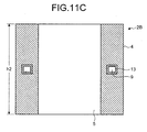
- material powder PM is sprayed on the shaft body part 4 from above the pipe 13 at the temperature lower than the melting point of the material powder PM by heated compressed gas, thereby the metal film is further deposited and formed until the height of the metal film has reached a predetermined height (h 2 ) as shown in FIG. 11C .
- the end and side faces, etc. of the shaft part 2B are smoothed by polishing, thereby the shaft-equipped heater unit 100B is manufactured.
- the shaft part 2B is formed on the rear surface 1b of the heater plate 1 by the cold spray device 50, and therefore the shaft-equipped heater unit 100B according to the third embodiment can suppress the accumulation of distortion due to a difference in thermal expansion between the heater plate 1 and the shaft part 2B and the occurrence of delamination or a crack that may occur when the heater plate 1 and the shaft part 2B formed of different material (such as material having low thermal conductivity) from the heater plate 1 are joined, for example, by brazing.
- different material such as material having low thermal conductivity
- the shaft part 2B is formed of the same material as the heater plate 1, for example, aluminum or aluminum alloy, the heat conduction from the heater plate 1 to the shaft part 2B can be suppressed by a cooling medium introduced into the cooling medium channel 9, and the temperature distribution of the heater plate 1 can be improved.
- material having lower thermal conductivity than material of the heater plate 1 is selected as material which constitutes the shaft part 2B, the heat conduction from the heater plate 1 to the shaft part 2B can be further reduced. And further, an amount of heat conducted to an end of the shaft part 2B on the side not in contact with the heater plate 1 is reduced, and therefore it is possible to prevent early deterioration of an O-ring used in the installation of the shaft-equipped heater unit 100B.
- FIG. 12 is an explanatory diagram showing an overview of a cold spray device 50A used in the manufacture of the shaft-equipped heater unit according to the fourth embodiment of the present invention.
- FIG. 13 is an enlarged cross-sectional view of a shaft part 2C of the shaft-equipped heater unit according to the fourth embodiment of the present invention.
- the shaft part 2C according to the fourth embodiment is formed of a first material identical to material constituting the heater plate 1 and a second material having lower thermal conductivity than the material constituting the heater plate 1.
- a first material identical to material constituting the heater plate 1 is aluminum (thermal conductivity: 100 to 240 W/m ⁇ K), and stainless steel (thermal conductivity: 16 to 20 W/m ⁇ K) is used as the material having lower thermal conductivity than the material constituting the heater plate 1.
- the cold spray device 50A for manufacturing the shaft-equipped heater unit according to the fourth embodiment includes a first powder supply unit 52A for storing and supplying aluminum powder used as the first material which is raw material and a second powder supply unit 52B for storing and supplying stainless steel powder used as the second material.
- Desired flow rates of gases are introduced into the first powder supply unit 52A and the second powder supply unit 52B by operating valves 51a and 51c installed in the gas introduction pipe 51, thereby the first material powder and the second material powder are supplied into the chamber 54 through powder supply pipes 52a and 52b together with the gases, respectively.
- the ratio between materials which constitute the shaft part 2C is changed by using the cold spray device 50A.
- the shaft part 2C is composed of a shaft body part 4A, a shaft body part 4B, a shaft body part 4C, and a shaft body part 4D.
- the shaft body part 4A is on the side of the heater plate 1, and the shaft body part 4D is on the side of a housing of the device.
- the shaft body part 4A on the side in contact with the heater plate 1 is constituted of only aluminum which is the first material;
- the shaft body part 4B is constituted of aluminum, which is the first material, and stainless steel, which is the second material, at a ratio of 3:7;
- the shaft body part 4C is constituted of aluminum, which is the first material, and stainless steel, which is the second material, at a ratio of 7:3;
- the shaft body part 4D is constituted of only stainless steel which is the second material.
- the valve 51a is operated so that only aluminum powder which is the first material is supplied into the chamber 54, and the aluminum powder is sprayed on the rear surface 1b of the heater plate 1 at a temperature lower than a melting point of material powder PM by heated compressed gas, thereby the shaft body part 4A is deposited and formed.
- the valves 51a and 51c are operated so that aluminum which is the first material and stainless steel which is the second material are supplied at a ratio of 3:7, and material powder PM is sprayed at a temperature lower than a melting point of the material powder PM by heated compressed gas, thereby the shaft body part 4B is deposited and formed.
- valves 51a and 51c are operated so that aluminum which is the first material and stainless steel which is the second material are supplied at a ratio of 7:3, and the shaft body part 4C is deposited and formed, and then, last, the valve 51c is operated so that only stainless steel powder which is the second material is supplied into the chamber 54, and the shaft body part 4D is deposited and formed.
- the shaft part 2C is formed on the rear surface 1b of the heater plate 1 by using, first, the first material identical to material constituting the heater plate 1 as a main component, and therefore the shaft-equipped heater unit according to the fourth embodiment can suppress the accumulation of distortion due to a difference in thermal expansion between the heater plate 1 and the shaft part 2C and the occurrence of interfacial delamination or crack, etc.
- the second material having lower thermal conductivity than the material of the heater plate 1 is selected as one of materials which constitute the shaft part 2C, and the proportion of the second material increases in stages from one end on the side of the heater plate 1 to the other end, and therefore the heat conduction from the heater plate 1 to the shaft part 2C can be reduced.
- an end of the shaft part 2C on the side not in contact with the heater plate 1 is formed of material having low thermal conductivity, and therefore an amount of heat conducted to an end of the shaft part 2C on the side of the shaft body part 4D can be reduced, and it is possible to prevent early deterioration of an O-ring used in the installation in the housing that contains the shaft-equipped heater unit.
- the fourth embodiment there is explained the case where the ratio between materials constituting the shaft part 2C is changed in stages; alternatively, a shaft part can be formed by gradually changing the ratio between the two kinds of materials.
- the second material is one kind of metal or alloy; alternatively, two or more kinds of materials having lower thermal conductivities than the first material identical to material of the heater plate 1 can be used as the second material.
- a shaft-equipped heater unit that includes a shaft part whose constituent material is composed of a first material having about the same coefficient of thermal expansion as material constituting the heater plate 1 and a second material having lower thermal conductivity than the material constituting the heater plate 1, wherein the shaft part is formed in such a manner that an end of the shaft part on the side in contact with the heater plate 1 is formed mainly of the first material having about the same coefficient of thermal expansion as the heater plate 1, and the proportion of the second material constituting the shaft part increases gradually from the side of the heater plate 1 to the other end.
- the heater plate side of the shaft part is formed mainly of the first material having about the same thermal conductivity as material of the heater plate, and therefore, just like the fourth embodiment, the shaft-equipped heater unit according to the variation can suppress the accumulation of distortion due to a difference in thermal expansion between the heater plate 1 and the shaft part and the occurrence of interfacial delamination or crack, etc. Furthermore, the shaft part is formed so that the proportion of the second material having low thermal conductivity, which constitutes the shaft part, increases gradually from the side of the heater plate 1 to the other end, and therefore the heat conduction from the heater plate 1 to the shaft part can be reduced.
- an end of the shaft part on the side not in contact with the heater plate 1 is formed of material having low thermal conductivity, and therefore an amount of heat conducted to an end of the shaft part on the side of a shaft body part can be reduced, and it is possible to prevent early deterioration of an O-ring used in the installation in the housing that contains the shaft-equipped heater unit.
- the present invention is available in a shaft-equipped heater unit that performs precise temperature control of a heater plate and a method for manufacturing the shaft-equipped heater unit, and is useful especially in semiconductor manufacturing equipment.
Landscapes
- Chemical & Material Sciences (AREA)
- Engineering & Computer Science (AREA)
- Chemical Kinetics & Catalysis (AREA)
- Materials Engineering (AREA)
- Mechanical Engineering (AREA)
- Metallurgy (AREA)
- Organic Chemistry (AREA)
- Ceramic Engineering (AREA)
- Inorganic Chemistry (AREA)
- Resistance Heating (AREA)
- Multiple-Way Valves (AREA)
- Details Of Valves (AREA)
Abstract
Description
- The present invention relates to a shaft-equipped heater unit for supporting and heating a semiconductor substrate and a method for manufacturing the shaft-equipped heater unit.
- In a manufacturing process of a semiconductor substrate, such as at an annealing step, the semiconductor substrate is treated with heat in a vacuum chamber. In such a process, uniformly heating the semiconductor substrate to reduce the temperature distribution has a great influence on the yield; therefore, more precise temperature control is desired.
- In the heat treatment of the semiconductor substrate, a shaft-equipped heater for supporting and heating the semiconductor substrate is used. The shaft-equipped heater is composed of a sheath heater-embedded heater plate on which the semiconductor substrate which is an object to be heated is placed and a shaft for supporting the heater plate. The shaft-equipped heater having this configuration has a problem that there is a decrease in temperature of a plate central part because a shaft central part is less subject to heat input due to a constraint on routing of a sheath heater wire, and also heat dissipation via the shaft is likely to occur.
- Meanwhile, there has been proposed a technology to improve the temperature distribution of a heater plate in such a manner that the heater plate constituted of metal or metal alloy having high thermal conductivity and a shaft constituted of metal or metal alloy having lower thermal conductivity than material of the heater plate are joined by brazing or the like, thereby suppressing the heat conduction to the shaft.
- Furthermore, there has been proposed a ceramic heater whose heater plate is a ceramic sintered body, wherein a shaft part formed of material having lower thermal conductivity than a heater plate part and the heater plate part are joined (see Patent Literature 1).
- Patent Literature 1: Japanese Laid-open Patent Publication No.
2005-166368 - However, when different materials are joined by brazing or the like, there arises a problem that distortion due to a difference in thermal expansion between the different materials is accumulated because of high joining temperature, and it is difficult to improve the temperature distribution because of constraints on selectable materials in terms of a melting point of material and joining temperature, etc.
- The present invention has been made in view of the above, and an object of the present invention is to provide a shaft-equipped heater unit and shaft-equipped heater unit manufacturing method capable of improving the temperature distribution of a heater and solving the distortion caused when different materials are joined and the interfacial delamination or crack.
- To solve the problem described above and achieve the object, a shaft-equipped heater unit includes: a heater plate that heats an object to be heated placed thereon; and a shaft that supports the heater plate, wherein the shaft is formed by spraying material powder which constitutes the shaft on the heater plate at a temperature lower than a melting point of the material powder by heated compressed gas.
- Moreover, in the above-described shaft-equipped heater unit according to the present invention, the heater plate is constituted of a metal or alloy having high thermal conductivity, and the shaft is constituted of a metal or alloy having lower thermal conductivity than the material constituting the heater plate.
- Moreover, in the above-described shaft-equipped heater unit according to the present invention, the shaft comprises a heat-conduction suppressor that suppresses heat conduction from the heater plate to the shaft in a cylindrical body part thereof.
- Moreover, in the above-described shaft-equipped heater unit according to the present invention, the heat-conduction suppressor is a heat insulation groove.
- Moreover, in the above-described shaft-equipped heater unit according to the present invention, the heat-conduction suppressor is a cooling medium channel.
- Moreover, in the above-described shaft-equipped heater unit according to the present invention, the shaft is formed of a first material identical to material constituting the heater plate and a second material having lower thermal conductivity than the material constituting the heater plate, and an end of the shaft on the side in contact with the heater plate is formed of the first material as a main component, and proportion of the first material constituting the shaft decreases gradually from the end on the side of the heater plate to another end.
- Moreover, a method for manufacturing a shaft-equipped heater unit comprising a heater plate for heating an object to be heated placed thereon and a shaft for supporting the heater plate according to the present invention includes a shaft forming step of forming the shaft by spraying material powder, which constitutes the shaft, on the heater plate at a temperature lower than a melting point of the material powder by heated compressed gas.
- Moreover, in the above-described method for manufacturing a shaft-equipped heater unit, the shaft forming step includes: a first spraying step of spraying material powder, which constitutes the shaft, on the heater plate at a temperature lower than a melting point of the material powder by heated compressed gas; a groove forming step of forming a heat insulation groove on the shaft formed at the first spraying step; and a second spraying step of, after the groove forming step, further spraying material powder which constitutes the shaft on the shaft on which the heat insulation groove has been formed at a temperature lower than a melting point of the material powder by heated compressed gas.
- Moreover, in the above-described method for manufacturing a shaft-equipped heater unit, the shaft forming step includes: a first spraying step of spraying material powder, which constitutes the shaft, on the heater plate at a temperature lower than a melting point of the material powder by heated compressed gas; a pipe placing step of placing a cooling medium pipe in the shaft formed at the first spraying step; and a second spraying step of, after the pipe placing step, further spraying material powder which constitutes the shaft on the shaft in which the pipe has been placed at a temperature lower than a melting point of the material powder by heated compressed gas.
- Moreover, in the above-described method for manufacturing a shaft-equipped heater unit, the shaft is formed of a first material identical to material constituting the heater plate and a second material having lower thermal conductivity than the material constituting the heater plate, and an end of the shaft on the side in contact with the heater plate is formed of the first material as a main component, and proportion of the first material constituting the shaft decreases gradually from the end on the side of the heater plate to another end. Advantageous Effects of Invention
- In a shaft-equipped heater unit and its manufacturing method according to the present invention, a shaft is formed by spraying material powder, which constitutes the shaft, directly on a heater plate at a temperature lower than a melting point of the material powder by heated compressed gas; therefore, there are achieved effects that material hard to be joined to the heater plate by brazing can be selected as material of the shaft, and delamination or a crack, etc. at the interface between the heater plate and the shaft due to thermal fatigue can be prevented effectively.
-
-
FIG. 1 is a cross-sectional view showing a configuration of a shaft-equipped heater unit according to a first embodiment of the present invention. -
FIG. 2 is a cross-sectional view of the shaft-equipped heater unit along a line A-A shown inFIG. 1 . -
FIG. 3 is an explanatory diagram showing an overview of a cold spray device used in the manufacture of the shaft-equipped heater unit according to the first embodiment of the present invention. -
FIG. 4 is a cross-sectional view showing a configuration of a shaft-equipped heater unit according to a second embodiment of the present invention. -
FIG. 5 is a cross-sectional view of the shaft-equipped heater unit along a line B-B shown inFIG. 4 . -
FIG. 6 is an enlarged cross-sectional view of a heat insulation groove and its surrounding part of the shaft-equipped heater unit shown inFIG. 4 . -
FIG. 7A is a cross-sectional view showing a manufacturing process of the shaft-equipped heater unit according to the second embodiment of the present invention. -
FIG. 7B is a cross-sectional view showing the manufacturing process of the shaft-equipped heater unit according to the second embodiment of the present invention. -
FIG. 7C is a cross-sectional view showing the manufacturing process of the shaft-equipped heater unit according to the second embodiment of the present invention. -
FIG. 7D is a cross-sectional view showing the manufacturing process of the shaft-equipped heater unit according to the second embodiment of the present invention. -
FIG. 8 is a cross-sectional view showing a configuration of a shaft-equipped heater unit according to a third embodiment of the present invention. -
FIG. 9 is a cross-sectional view of the shaft-equipped heater unit along a line C-C shown inFIG. 8 . -
FIG. 10 is an enlarged cross-sectional view of a cooling medium channel and its surrounding part of the shaft-equipped heater unit shown inFIG. 8 . -
FIG. 11A is a cross-sectional view showing a manufacturing process of the shaft-equipped heater unit according to the third embodiment of the present invention. -
FIG. 11B is a cross-sectional view showing the manufacturing process of the shaft-equipped heater unit according to the third embodiment of the present invention. -
FIG. 11C is a cross-sectional view showing the manufacturing process of the shaft-equipped heater unit according to the third embodiment of the present invention. -
FIG. 12 is an explanatory diagram showing an overview of a cold spray device used in the manufacture of a shaft-equipped heater unit according to a fourth embodiment of the present invention. -
FIG. 13 is an enlarged cross-sectional view of a shaft part of the shaft-equipped heater unit according to the fourth embodiment of the present invention. - Embodiments of a shaft-equipped heater unit and method for manufacturing the shaft-equipped heater unit according to the present invention will be explained in detail below on the basis of accompanying drawings. Incidentally, the present invention is not limited to these embodiments, and various modifications can be made without departing from the scope of the present invention.
-
FIG. 1 is a cross-sectional view showing a configuration of a shaft-equippedheater unit 100 according to a first embodiment of the present invention. The shaft-equippedheater unit 100 includes a roughly-discoid heater plate 1 that an object to be heated is placed on a placingsurface 1a thereof and ashaft part 2 that is joined to the center of arear surface 1b of theheater plate 1 and supports theheater plate 1. In the first embodiment, thediscoid heater plate 1 is used; however, theheater plate 1 is not limited to this shape, and can be formed into any shape taking into account the shape of the heated object, etc.; for example, theheater plate 1 can be formed into a rectangular shape. -
FIG. 2 is a cross-sectional view of the shaft-equippedheater unit 100 along a line A-A shown inFIG. 1 . As shown inFIG. 2 , a spiral-shaped sheath heater 3 is installed in theheater plate 1. Thesheath heater 3 includes a resistance heating element, such as a nichrome wire, and an insulator formed by solidification of powder such as magnesia powder on the outer periphery of the resistance heating element, and supplies electric power to the resistance heating element to generate heat. As a configuration of thesheath heater 3, besides the spiral shape shown inFIG. 2 , any desired shape can be adopted. - The
heater plate 1 is formed of a metal or alloy having high thermal conductivity, and material of theheater plate 1 is arbitrarily selected on the basis of an operating temperature range of the shaft-equippedheater unit 100. As material of theheater plate 1, for example, aluminum or aluminum alloy (thermal conductivity: 100 to 240 W/m·K) is preferably used; however, material of theheater plate 1 is not limited to this, and can be selected from iron or iron alloy (thermal conductivity: 10 to 80 W/m·K), copper or copper alloy (thermal conductivity: 100 to 400 W/m·K), nickel or nickel alloy (thermal conductivity: 5 to 100 W/m·K), titanium or titanium alloy (thermal conductivity: 5 to 30 W/m·K), indium (thermal conductivity: 82 W/m·K at normal temperature), lead (thermal conductivity: 35 W/m·K at normal temperature), magnesium (thermal conductivity: 156 W/m·K at normal temperature), tin (thermal conductivity: 67 W/m·K at normal temperature), silver (thermal conductivity: 420 W/m·K at normal temperature), and zinc (thermal conductivity: 116 W/m·K at normal temperature), etc. - The
shaft part 2 is composed of a cylindricalshaft body part 4 that supports theheater plate 1 and has ahollow portion 5 into which apower supply line 3a for the supply of power from an external power source is inserted. Theshaft part 2 is laminated and formed on therear surface 1b of theheater plate 1 by a cold spray device to be described later. - Material which constitutes the
shaft part 2 is selected from metals or alloys that have lower thermal conductivity than material constituting theheater plate 1. Theshaft part 2 is formed of a metal or alloy having lower thermal conductivity than material constituting theheater plate 1, thereby the heat conduction from theheater plate 1 to theshaft part 2 can be suppressed. As material of theshaft part 2, if theheater plate 1 is constituted of aluminum or aluminum alloy (thermal conductivity: 100 to 240 W/m·K), a metal or alloy having lower thermal conductivity than aluminum or aluminum alloy, such as stainless steel (thermal conductivity: 16 to 20 W/m·K), is preferably used. - Subsequently, a method for manufacturing the shaft-equipped
heater unit 100 according to the first embodiment is explained with reference toFIG. 3. FIG. 3 is an explanatory diagram showing an overview of acold spray device 50 used in the manufacture of the shaft-equipped heater unit according to the first embodiment of the present invention. - As shown in
FIG. 3 , thecold spray device 50 includes agas introduction pipe 51 through which inert gas, such as helium (He) and nitrogen (N2), or gas (working gas), such as air, is introduced from a gas supply source, apowder supply unit 52 that supplies material powder PM which is raw material, aheater 53 that heats the gas introduced through thegas introduction pipe 51 to a desired temperature, achamber 54 in which the material powder PM is mixed with the gas so as to be sprayed, and anozzle 55 that sprays the material powder PM. The material powder PM here is powder of the material which constitutes theshaft part 2. - The
powder supply unit 52 contains fine material powder PM (for example, with a particle diameter of about 10 to 100 µm). A desired flow rate of gas is introduced into thepowder supply unit 52 by operating avalve 51a installed in thegas introduction pipe 51, thereby the material powder PM is supplied into thechamber 54 through apowder supply pipe 52a together with the gas. - The
heater 53 heats the introduced gas to, for example, about 50°C to 700°C. An upper limit of this heating temperature shall be less than a melting point of material because solid-phase material powder PM is sprayed on therear surface 1b of theheater plate 1. More preferably, the upper temperature limit shall be kept to a Celsius temperature of about 60% or less of the melting point. This is because the higher the heating temperature is, the more likely the material powder PM is to be oxidized. - The gas heated by the
heater 53 is introduced into thechamber 54 through agas pipe 53a. Incidentally, a flow rate of the gas introduced into thechamber 54 is adjusted by avalve 51b installed in thegas introduction pipe 51. The heated compressed gas is made into a supersonic flow (about 340 m/s or more) by the convergent-divergent nozzle 55, and the material powder PM supplied into thechamber 54 is accelerated by being thrown into the supersonic gas flow, and the material powder PM remaining the solid phase collides with base material, i.e., theheater plate 1 in the first embodiment at high speed, thereby a film is formed. - As shown in
FIG. 3 , the material powder PM is deposited by moving thenozzle 55 in a direction of arrow X and a direction of arrow Y, thereby theshaft body part 4 is formed on therear surface 1b of theheater plate 1. Incidentally, any device capable of forming a film by making solid-phase material powder PM collide with base material can be used in the manufacture of the shaft-equippedheater unit 100 according to the first embodiment, and it is not limited to thecold spray device 50 shown inFIG. 3 . - After the desired-shaped
shaft part 2 has been formed on therear surface 1b of theheater plate 1 by the above-describedcold spray device 50, the material powder PM attached to an unwanted part is removed, and the end and side faces, etc. of theshaft part 2 are smoothed by polishing, thereby the shaft-equippedheater unit 100 is manufactured. - The material powder PM collides with the surface of a lower layer (the
rear surface 1b of theheater plate 1 or theshaft body part 4 deposited till that time) at high speed and bites into the lower layer, and also is deformed and attached to the lower layer, so that theshaft part 2 manufactured in this way is a metal film laminate adhered strongly to the lower layer. The shaft-equippedheater unit 100 according to the first embodiment can observe a phenomenon where the metal film bites into therear surface 1b (called an anchor effect) at the interface between theshaft body part 4 and therear surface 1b of theheater plate 1, and theshaft body part 4 is closely joined to theheater plate 1 formed of a different kind of metal without leaving any gap between them. - The
shaft part 2 is firmly fixed to therear surface 1b of theheater plate 1, so that the shaft-equippedheater unit 100 according to the first embodiment can suppress the occurrence of delamination or a crack in between theheater plate 1 and theshaft part 2 that may occur when theheater plate 1 and theshaft part 2 formed of different material (such as material having low thermal conductivity) from theheater plate 1 are joined, for example, by brazing. Furthermore, when theheater plate 1 is aluminum or aluminum alloy, it used to be difficult to join theshaft part 2 formed of stainless steel to theheater plate 1 by brazing; however, according to thecold spray device 50, even when difficult-to-braze material is selected as raw material of theshaft part 2, it can perform the joining of theshaft part 2 to theheater plate 1 firmly, and therefore it is possible to broaden options for material of theshaft part 2. - Moreover, when the
heater plate 1 is formed of aluminum or aluminum alloy, and theshaft part 2 is formed of, for example, stainless steel having lower thermal conductivity than aluminum or aluminum alloy, the heat conduction from theheater plate 1 to theshaft part 2 is suppressed, and the temperature distribution of theheater plate 1 can be improved. This allows uniform heating of an object to be heated, and semiconductor manufacturing equipment using the shaft-equippedheater unit 100 can manufacture stable-quality semiconductor substrates. - As described above, the
shaft part 2 is formed by spraying material powder PM, which constitutes theshaft part 2, on therear surface 1b of theheater plate 1 at a temperature lower than a melting point of the material powder PM by heated compressed gas, and therefore the shaft-equippedheater unit 100 according to the first embodiment can suppress the accumulation of distortion due to a difference in thermal expansion caused by brazing of different materials and the occurrence of interfacial delamination or crack, etc. due to long-term use. Furthermore, a metal or alloy having lower thermal conductivity than material of theheater plate 1 is selected as material which constitutes theshaft part 2, thereby the heat conduction from theheater plate 1 to theshaft part 2 is suppressed, and the temperature distribution of theheater plate 1 can be improved. - A shaft-equipped heater unit according to a second embodiment is explained with reference to drawings.
FIG. 4 is a cross-sectional view showing a configuration of a shaft-equippedheater unit 100A according to the second embodiment of the present invention.FIG. 5 is a cross-sectional view of the shaft-equippedheater unit 100A along a line B-B shown inFIG. 4 .FIG. 6 is an enlarged cross-sectional view of aheat insulation groove 6 and its surrounding part of the shaft-equippedheater unit 100A shown inFIG. 4 . The shaft-equippedheater unit 100A according to the second embodiment has theheat insulation groove 6 in theshaft body part 4. - The
heat insulation groove 6 is a groove that is rectangular in cross-section and is formed roughly in the center of the cylindricalshaft body part 4, and is formed so as to completely surround the section of theshaft body part 4 as shown inFIG. 5 . Furthermore, the shaft-equippedheater unit 100A has a structure where theheat insulation groove 6 is covered with acover part 7 as shown inFIG. 6 . Thecover part 7 is shaped like a disc having a diameter larger than an outer diameter of theheat insulation groove 6. The cross-sectional shape of theheat insulation groove 6 is not limited to a rectangular shape, and can be a round shape, etc. as long as theheat insulation groove 6 has a structure where air (thermal conductivity: 0.02 W/m·K) as heat insulating material is present in theheat insulation groove 6. - Subsequently, a manufacturing process of a
shaft part 2A having theheat insulation groove 7 is explained with reference toFIGS. 7A to 7D . - First, as shown in
FIG. 7A , by using thecold spray device 50, material powder PM, which constitutes theshaft body part 4, is sprayed on therear surface 1b of theheater plate 1 at a temperature lower than a melting point of the material powder PM by heated compressed gas, thereby a metal film is deposited and formed. When the height of the metal film has reached a predetermined height (h1), the deposition of the metal film is terminated for the moment. - After the end face of the
shaft body part 4 has been smoothed, theheat insulation groove 6 is formed by cutting work or the like as shown inFIG. 7B . After that, acover support part 8 on which thecover part 7 is placed is formed by further cutting off the periphery of an opening of theheat insulation groove 6. - After that, the
cover part 7 is placed on thecover support part 8 as shown inFIG. 7C , and by using thecold spray device 50 again, material powder PM is sprayed on theshaft body part 4 so as to cover thecover part 7 at the temperature lower than the melting point of the material powder PM by heated compressed gas, thereby the metal film is further deposited and formed until the height of the metal film has reached a predetermined height (h2). After the completion of the deposition of the metal film, the end and side faces, etc. of theshaft part 2A are smoothed by polishing, thereby the shaft-equippedheater unit 100A is manufactured. - Incidentally, the diameter of the
cover part 7 shall be larger than an outer diameter of the opening of theheat insulation groove 6 so that the material powder PM does not go into theheat insulation groove 6, and also shall be smaller than the diameter of thecover support part 8 so that thecover part 7 is supported by thecover support part 8. Furthermore, the height of thecover part 7 does not have to be the same height as thecover support part 8 as long as thecover part 7 can seal air used as heat insulating material in theheat insulation groove 6. - As described above, the
shaft part 2A is formed on therear surface 1b of theheater plate 1 by thecold spray device 50, and therefore the shaft-equippedheater unit 100A according to the second embodiment can suppress the accumulation of distortion due to a difference in thermal expansion between theheater plate 1 and theshaft part 2A and the occurrence of delamination or a crack that may occur when theheater plate 1 and theshaft part 2A formed of different material (such as material having low thermal conductivity) from theheater plate 1 are joined, for example, by brazing. Furthermore, even when theshaft part 2A is formed of the same material as theheater plate 1, for example, aluminum or aluminum alloy, the heat conduction from theheater plate 1 to theshaft part 2A can be suppressed by the heat insulating material (air) sealed in theheat insulation groove 6, and the temperature distribution of theheater plate 1 can be improved. Moreover, when material having lower thermal conductivity than material of theheater plate 1 is selected as material which constitutes theshaft part 2A, the heat conduction from theheater plate 1 to theshaft part 2A can be further reduced. And further, an amount of heat conducted to an end of theshaft part 2A on the side not in contact with theheater plate 1 is reduced, and therefore it is possible to prevent deterioration of an O-ring used in the installation of the shaft-equippedheater unit 100A. - Incidentally, the shaft-equipped
heater unit 100A according to the second embodiment has the structure where thecover support part 8 is provided on the periphery of the opening of theheat insulation groove 6, and thecover part 7 is placed on thecover support part 8; alternatively, air can be sealed in theheat insulation groove 6 in such a manner that theheat insulation groove 6 is covered with thecover part 7 without forming thecover support part 8 and theshaft body part 4 is further formed on thecover part 7 by thecold spray device 50. - A shaft-equipped heater unit according to a third embodiment is explained with reference to drawings.
FIG. 8 is a cross-sectional view showing a configuration of a shaft-equippedheater unit 100B according to the third embodiment of the present invention.FIG. 9 is a cross-sectional view of the shaft-equippedheater unit 100B along a line C-C shown inFIG. 8 .FIG. 10 is an enlarged cross-sectional view of a cooling medium channel and its surrounding part of the shaft-equippedheater unit 100B shown inFIG. 8 . The shaft-equippedheater unit 100B according to the third embodiment has a coolingmedium channel 9 in theshaft body part 4. - The cooling
medium channel 9 is a flow channel that is rectangular in cross-section and is formed roughly in the center of the cylindricalshaft body part 4, and is formed so as to completely surround the section of theshaft body part 4 as shown inFIG. 9 . As shown inFIG. 10 , the coolingmedium channel 9 is formed of apipe 13, and the cross-sectional shape of the coolingmedium channel 9 can be formed into a round shape and a triangular shape, etc. by changing the cross-sectional shape of thepipe 13. Material constituting thepipe 13 is selected according to the kind of a cooling medium; when city water is used as a cooling medium, corrosion-resistant material, such as copper, copper alloy, stainless steel, nickel, nickel alloy, tantalum, tantalum alloy, titanium, and titanium alloy, is used. Incidentally, the medium is not limited to liquid, and can be gas. - The shaft-equipped
heater unit 100B has a structure where a cooling medium is introduced into the coolingmedium channel 9 from aninflow port 11 connected to acooling pipe 10, and heat is absorbed from theshaft body part 4 by passage of the cooling medium through the coolingmedium channel 9, and the cooling medium flows out from anoutflow port 12 connected to a cooling pipe (not shown). - Subsequently, a manufacturing process of a
shaft part 2B having the coolingmedium channel 9 is explained with reference toFIGS. 11A to 11C . - First, as shown in
FIG. 11A , by using thecold spray device 50, material powder PM, which constitutes theshaft body part 4, is sprayed on therear surface 1b of theheater plate 1 at a temperature lower than a melting point of the material powder PM by heated compressed gas, thereby a metal film is deposited and formed. When the height of the metal film has reached a predetermined height (h1), the deposition of the metal film is terminated for the moment. - After the end face of the
shaft body part 4 has been smoothed, thepipe 13 is placed on the end face of theshaft body part 4 as shown inFIG. 11B . - After that, material powder PM is sprayed on the
shaft body part 4 from above thepipe 13 at the temperature lower than the melting point of the material powder PM by heated compressed gas, thereby the metal film is further deposited and formed until the height of the metal film has reached a predetermined height (h2) as shown inFIG. 11C . After the completion of the deposition of the metal film, the end and side faces, etc. of theshaft part 2B are smoothed by polishing, thereby the shaft-equippedheater unit 100B is manufactured. - As described above, the
shaft part 2B is formed on therear surface 1b of theheater plate 1 by thecold spray device 50, and therefore the shaft-equippedheater unit 100B according to the third embodiment can suppress the accumulation of distortion due to a difference in thermal expansion between theheater plate 1 and theshaft part 2B and the occurrence of delamination or a crack that may occur when theheater plate 1 and theshaft part 2B formed of different material (such as material having low thermal conductivity) from theheater plate 1 are joined, for example, by brazing. Furthermore, even when theshaft part 2B is formed of the same material as theheater plate 1, for example, aluminum or aluminum alloy, the heat conduction from theheater plate 1 to theshaft part 2B can be suppressed by a cooling medium introduced into the coolingmedium channel 9, and the temperature distribution of theheater plate 1 can be improved. Moreover, when material having lower thermal conductivity than material of theheater plate 1 is selected as material which constitutes theshaft part 2B, the heat conduction from theheater plate 1 to theshaft part 2B can be further reduced. And further, an amount of heat conducted to an end of theshaft part 2B on the side not in contact with theheater plate 1 is reduced, and therefore it is possible to prevent early deterioration of an O-ring used in the installation of the shaft-equippedheater unit 100B. - A shaft-equipped heater unit according to a fourth embodiment is explained with reference to drawings.
FIG. 12 is an explanatory diagram showing an overview of acold spray device 50A used in the manufacture of the shaft-equipped heater unit according to the fourth embodiment of the present invention.FIG. 13 is an enlarged cross-sectional view of a shaft part 2C of the shaft-equipped heater unit according to the fourth embodiment of the present invention. - The shaft part 2C according to the fourth embodiment is formed of a first material identical to material constituting the
heater plate 1 and a second material having lower thermal conductivity than the material constituting theheater plate 1. For example, there is explained a case where the material constituting theheater plate 1 is aluminum (thermal conductivity: 100 to 240 W/m·K), and stainless steel (thermal conductivity: 16 to 20 W/m·K) is used as the material having lower thermal conductivity than the material constituting theheater plate 1. - As shown in
FIG. 12 , thecold spray device 50A for manufacturing the shaft-equipped heater unit according to the fourth embodiment includes a firstpowder supply unit 52A for storing and supplying aluminum powder used as the first material which is raw material and a secondpowder supply unit 52B for storing and supplying stainless steel powder used as the second material. - Desired flow rates of gases are introduced into the first
powder supply unit 52A and the secondpowder supply unit 52B by operatingvalves gas introduction pipe 51, thereby the first material powder and the second material powder are supplied into thechamber 54 throughpowder supply pipes - In the fourth embodiment, the ratio between materials which constitute the shaft part 2C is changed by using the
cold spray device 50A. As shown inFIG. 13 , the shaft part 2C is composed of a shaft body part 4A, ashaft body part 4B, ashaft body part 4C, and ashaft body part 4D. The shaft body part 4A is on the side of theheater plate 1, and theshaft body part 4D is on the side of a housing of the device. - In the shaft part 2C, the shaft body part 4A on the side in contact with the
heater plate 1 is constituted of only aluminum which is the first material; theshaft body part 4B is constituted of aluminum, which is the first material, and stainless steel, which is the second material, at a ratio of 3:7; theshaft body part 4C is constituted of aluminum, which is the first material, and stainless steel, which is the second material, at a ratio of 7:3; and theshaft body part 4D is constituted of only stainless steel which is the second material. The above-described respective ratios of the first material to the second material for theshaft body parts heater plate 1 to the other end. - In the manufacture of the shaft part 2C, first, the
valve 51a is operated so that only aluminum powder which is the first material is supplied into thechamber 54, and the aluminum powder is sprayed on therear surface 1b of theheater plate 1 at a temperature lower than a melting point of material powder PM by heated compressed gas, thereby the shaft body part 4A is deposited and formed. After the height of a metal film has reached a predetermined height, thevalves shaft body part 4B is deposited and formed. - After that, the
valves shaft body part 4C is deposited and formed, and then, last, thevalve 51c is operated so that only stainless steel powder which is the second material is supplied into thechamber 54, and theshaft body part 4D is deposited and formed. - The shaft part 2C is formed on the
rear surface 1b of theheater plate 1 by using, first, the first material identical to material constituting theheater plate 1 as a main component, and therefore the shaft-equipped heater unit according to the fourth embodiment can suppress the accumulation of distortion due to a difference in thermal expansion between theheater plate 1 and the shaft part 2C and the occurrence of interfacial delamination or crack, etc. Furthermore, the second material having lower thermal conductivity than the material of theheater plate 1 is selected as one of materials which constitute the shaft part 2C, and the proportion of the second material increases in stages from one end on the side of theheater plate 1 to the other end, and therefore the heat conduction from theheater plate 1 to the shaft part 2C can be reduced. Moreover, an end of the shaft part 2C on the side not in contact with theheater plate 1 is formed of material having low thermal conductivity, and therefore an amount of heat conducted to an end of the shaft part 2C on the side of theshaft body part 4D can be reduced, and it is possible to prevent early deterioration of an O-ring used in the installation in the housing that contains the shaft-equipped heater unit. - Incidentally, in the fourth embodiment, there is explained the case where the ratio between materials constituting the shaft part 2C is changed in stages; alternatively, a shaft part can be formed by gradually changing the ratio between the two kinds of materials. Furthermore, in the second embodiment, there is explained the case where the second material is one kind of metal or alloy; alternatively, two or more kinds of materials having lower thermal conductivities than the first material identical to material of the
heater plate 1 can be used as the second material. - Moreover, as a variation of the fourth embodiment, there can be embodied a shaft-equipped heater unit that includes a shaft part whose constituent material is composed of a first material having about the same coefficient of thermal expansion as material constituting the
heater plate 1 and a second material having lower thermal conductivity than the material constituting theheater plate 1, wherein the shaft part is formed in such a manner that an end of the shaft part on the side in contact with theheater plate 1 is formed mainly of the first material having about the same coefficient of thermal expansion as theheater plate 1, and the proportion of the second material constituting the shaft part increases gradually from the side of theheater plate 1 to the other end. - The heater plate side of the shaft part is formed mainly of the first material having about the same thermal conductivity as material of the heater plate, and therefore, just like the fourth embodiment, the shaft-equipped heater unit according to the variation can suppress the accumulation of distortion due to a difference in thermal expansion between the
heater plate 1 and the shaft part and the occurrence of interfacial delamination or crack, etc. Furthermore, the shaft part is formed so that the proportion of the second material having low thermal conductivity, which constitutes the shaft part, increases gradually from the side of theheater plate 1 to the other end, and therefore the heat conduction from theheater plate 1 to the shaft part can be reduced. Moreover, an end of the shaft part on the side not in contact with theheater plate 1 is formed of material having low thermal conductivity, and therefore an amount of heat conducted to an end of the shaft part on the side of a shaft body part can be reduced, and it is possible to prevent early deterioration of an O-ring used in the installation in the housing that contains the shaft-equipped heater unit. - The present invention is available in a shaft-equipped heater unit that performs precise temperature control of a heater plate and a method for manufacturing the shaft-equipped heater unit, and is useful especially in semiconductor manufacturing equipment.
-
- 1
- Heater plate
- 2, 2A, 2B
- Shaft part
- 3
- Sheath heater
- 3a
- Power supply line
- 4
- Shaft body part
- 5
- Hollow portion
- 6
- Heat insulation groove
- 7
- Cover part
- 8
- Cover support part
- 9
- Cooling medium channel
- 10
- Cooling pipe
- 11
- Inflow port
- 12
- Outflow port
- 13
- Pipe
- 50, 50A
- Cold spray device
- 51
- Gas introduction pipe
- 51a, 51b, 51c
- Valve
- 52
- Powder supply unit
- 53
- Heater
- 54
- Chamber
- 55
- Nozzle
- 100, 100A, 100B
- Shaft-equipped heater unit
Claims (10)
- A shaft-equipped heater unit comprising:a heater plate that heats an object to be heated placed thereon; anda shaft that supports the heater plate, whereinthe shaft is formed by spraying material powder which constitutes the shaft on the heater plate at a temperature lower than a melting point of the material powder by heated compressed gas.
- The shaft-equipped heater unit according to claim 1, wherein
the heater plate is constituted of a metal or alloy having high thermal conductivity, and
the shaft is constituted of a metal or alloy having lower thermal conductivity than the material constituting the heater plate. - The shaft-equipped heater unit according to claim 1 or 2, wherein
the shaft comprises a heat-conduction suppressor that suppresses heat conduction from the heater plate to the shaft in a cylindrical body part thereof. - The shaft-equipped heater unit according to claim 3, wherein
the heat-conduction suppressor is a heat insulation groove. - The shaft-equipped heater unit according to claim 3, wherein
the heat-conduction suppressor is a cooling medium channel. - The shaft-equipped heater unit according to claim 1, wherein
the shaft is formed of a first material identical to material constituting the heater plate and a second material having lower thermal conductivity than the material constituting the heater plate, and
an end of the shaft on the side in contact with the heater plate is formed of the first material as a main component, and proportion of the first material constituting the shaft decreases gradually from the end on the side of the heater plate to another end. - A method for manufacturing a shaft-equipped heater unit comprising a heater plate for heating an object to be heated placed thereon and a shaft for supporting the heater plate, the shaft-equipped heater unit manufacturing method comprising:a shaft forming step of forming the shaft by spraying material powder, which constitutes the shaft, on the heater plate at a temperature lower than a melting point of the material powder by heated compressed gas.
- The shaft-equipped heater unit manufacturing method according to claim 7, wherein
the shaft forming step comprises:a first spraying step of spraying material powder, which constitutes the shaft, on the heater plate at a temperature lower than a melting point of the material powder by heated compressed gas;a groove forming step of forming a heat insulation groove on the shaft formed at the first spraying step; anda second spraying step of, after the groove forming step, further spraying material powder which constitutes the shaft on the shaft on which the heat insulation groove has been formed at a temperature lower than a melting point of the material powder by heated compressed gas. - The shaft-equipped heater unit manufacturing method according to claim 7, wherein
the shaft forming step comprises:a first spraying step of spraying material powder, which constitutes the shaft, on the heater plate at a temperature lower than a melting point of the material powder by heated compressed gas;a pipe placing step of placing a cooling medium pipe in the shaft formed at the first spraying step; anda second spraying step of, after the pipe placing step, further spraying material powder which constitutes the shaft on the shaft in which the pipe has been placed at a temperature lower than a melting point of the material powder by heated compressed gas. - The shaft-equipped heater unit manufacturing method according to claim 7, wherein
the shaft is formed of a first material identical to material constituting the heater plate and a second material having lower thermal conductivity than the material constituting the heater plate, and
an end of the shaft on the side in contact with the heater plate is formed of the first material as a main component, and proportion of the first material constituting the shaft decreases gradually from the end on the side of the heater plate to another end.
Applications Claiming Priority (2)
| Application Number | Priority Date | Filing Date | Title |
|---|---|---|---|
| JP2011122309A JP5712054B2 (en) | 2011-05-31 | 2011-05-31 | Heater unit with shaft and manufacturing method of heater unit with shaft |
| PCT/JP2012/063797 WO2012165440A1 (en) | 2011-05-31 | 2012-05-29 | Shaft-equipped heater unit, and method for producing shaft-equipped heater unit |
Publications (2)
| Publication Number | Publication Date |
|---|---|
| EP2717650A1 true EP2717650A1 (en) | 2014-04-09 |
| EP2717650A4 EP2717650A4 (en) | 2014-12-31 |
Family
ID=47259294
Family Applications (1)
| Application Number | Title | Priority Date | Filing Date |
|---|---|---|---|
| EP20120792834 Withdrawn EP2717650A4 (en) | 2011-05-31 | 2012-05-29 | HEATING UNIT EQUIPPED WITH A SHAFT, AND METHOD FOR PRODUCING A HEATING UNIT EQUIPPED WITH A SHAFT |
Country Status (6)
| Country | Link |
|---|---|
| US (1) | US9414441B2 (en) |
| EP (1) | EP2717650A4 (en) |
| JP (1) | JP5712054B2 (en) |
| KR (1) | KR101513605B1 (en) |
| CN (1) | CN103597908B (en) |
| WO (1) | WO2012165440A1 (en) |
Cited By (1)
| Publication number | Priority date | Publication date | Assignee | Title |
|---|---|---|---|---|
| EP3726563A4 (en) * | 2017-12-13 | 2021-09-01 | Tokyo Electron Limited | FILM TRAINING DEVICE |
Families Citing this family (11)
| Publication number | Priority date | Publication date | Assignee | Title |
|---|---|---|---|---|
| JP2015214738A (en) * | 2014-05-13 | 2015-12-03 | 株式会社東芝 | Corrosion resistant metal member, heat sink for power device, rotating blade for generator and manufacturing method of corrosion resistant metal member |
| CA2984429A1 (en) * | 2015-06-29 | 2017-01-05 | Oerlikon Metco (Us) Inc. | Cold gas spray coating methods and compositions |
| DE102016103270B3 (en) * | 2016-02-24 | 2017-05-11 | Ev Group E. Thallner Gmbh | Apparatus and method for holding, rotating and heating and / or cooling a substrate |
| JP6704834B2 (en) * | 2016-10-28 | 2020-06-03 | 日本特殊陶業株式会社 | Heating device |
| JP6704836B2 (en) * | 2016-10-28 | 2020-06-03 | 日本特殊陶業株式会社 | Heating device |
| WO2018159189A1 (en) | 2017-02-28 | 2018-09-07 | 日本発條株式会社 | Substrate supporting unit and film forming device having substrate supporting unit |
| JP2020131271A (en) * | 2019-02-25 | 2020-08-31 | 株式会社神戸製鋼所 | Dissimilar metal joint manufacturing method and dissimilar metal joint |
| BE1027475B1 (en) * | 2020-01-22 | 2021-02-26 | Laser Eng Applications | Bulk heat treatment process and associated system |
| KR102649715B1 (en) * | 2020-10-30 | 2024-03-21 | 세메스 주식회사 | Surface treatment apparatus and surface treatment method |
| CN113333900A (en) * | 2021-06-28 | 2021-09-03 | 爱利彼半导体设备(中国)有限公司 | Integrated brazing heating plate |
| KR102866116B1 (en) | 2021-11-26 | 2025-09-30 | 삼성전자주식회사 | Semiconductor package |
Family Cites Families (32)
| Publication number | Priority date | Publication date | Assignee | Title |
|---|---|---|---|---|
| DE69016433T2 (en) | 1990-05-19 | 1995-07-20 | Papyrin Anatolij Nikiforovic | COATING METHOD AND DEVICE. |
| US6617553B2 (en) * | 1999-05-19 | 2003-09-09 | Applied Materials, Inc. | Multi-zone resistive heater |
| JP2001298020A (en) | 2000-04-18 | 2001-10-26 | Nhk Spring Co Ltd | Ceramic heater and film forming apparatus using the same |
| US7201940B1 (en) * | 2001-06-12 | 2007-04-10 | Advanced Cardiovascular Systems, Inc. | Method and apparatus for thermal spray processing of medical devices |
| JP3888531B2 (en) * | 2002-03-27 | 2007-03-07 | 日本碍子株式会社 | Ceramic heater, method for manufacturing ceramic heater, and buried article of metal member |
| US7476422B2 (en) * | 2002-05-23 | 2009-01-13 | Delphi Technologies, Inc. | Copper circuit formed by kinetic spray |
| JP2004296254A (en) * | 2003-03-27 | 2004-10-21 | Sumitomo Electric Ind Ltd | Ceramic heater and semiconductor or liquid crystal manufacturing apparatus equipped with the same |
| JP4008401B2 (en) * | 2003-09-22 | 2007-11-14 | 日本碍子株式会社 | Manufacturing method of substrate mounting table |
| JP2005109169A (en) * | 2003-09-30 | 2005-04-21 | Ngk Insulators Ltd | Substrate heating apparatus and manufacturing method thereof |
| JP2005166368A (en) * | 2003-12-01 | 2005-06-23 | Ngk Insulators Ltd | Heating device |
| JP4515755B2 (en) | 2003-12-24 | 2010-08-04 | 東京エレクトロン株式会社 | Processing equipment |
| JP2005216759A (en) * | 2004-01-30 | 2005-08-11 | Nhk Spring Co Ltd | Heater unit |
| JP2005285355A (en) * | 2004-03-26 | 2005-10-13 | Ngk Insulators Ltd | Heating device |
| US7126092B2 (en) | 2005-01-13 | 2006-10-24 | Watlow Electric Manufacturing Company | Heater for wafer processing and methods of operating and manufacturing the same |
| EP1806429B1 (en) * | 2006-01-10 | 2008-07-09 | Siemens Aktiengesellschaft | Cold spray apparatus and method with modulated gasstream |
| JP4889385B2 (en) * | 2006-07-07 | 2012-03-07 | 日本発條株式会社 | Heater unit and shaft |
| US8168926B2 (en) * | 2007-03-26 | 2012-05-01 | Ngk Insulators, Ltd. | Heating device |
| JP2008297615A (en) * | 2007-06-01 | 2008-12-11 | Tokyo Electron Ltd | Substrate mounting mechanism and substrate processing apparatus provided with the substrate mounting mechanism |
| JP4586823B2 (en) * | 2007-06-21 | 2010-11-24 | トヨタ自動車株式会社 | Film forming method, heat transfer member, power module, vehicle inverter, and vehicle |
| JP4241859B2 (en) * | 2007-07-19 | 2009-03-18 | トヨタ自動車株式会社 | Power module manufacturing method, power module, vehicle inverter, and vehicle |
| US7763325B1 (en) * | 2007-09-28 | 2010-07-27 | The United States Of America As Represented By The National Aeronautics And Space Administration | Method and apparatus for thermal spraying of metal coatings using pulsejet resonant pulsed combustion |
| JP2009127086A (en) * | 2007-11-22 | 2009-06-11 | Toyota Motor Corp | Heat transfer member and manufacturing method thereof |
| JP5080954B2 (en) * | 2007-12-17 | 2012-11-21 | 日本発條株式会社 | Heater unit and manufacturing method thereof |
| JP5087416B2 (en) | 2008-01-24 | 2012-12-05 | 日本碍子株式会社 | Ceramic heater and manufacturing method thereof |
| JP5186528B2 (en) * | 2010-04-23 | 2013-04-17 | 日本発條株式会社 | Conductive member and manufacturing method thereof |
| JP5162621B2 (en) * | 2010-05-07 | 2013-03-13 | 日本発條株式会社 | Temperature control device, cooling device, and method of manufacturing temperature control device |
| JP5666167B2 (en) | 2010-05-07 | 2015-02-12 | 日本発條株式会社 | Stage heater and shaft manufacturing method |
| JP5449045B2 (en) | 2010-06-15 | 2014-03-19 | 日本発條株式会社 | Heater unit with shaft and heater unit manufacturing method with shaft |
| JP5463224B2 (en) * | 2010-07-09 | 2014-04-09 | 日本発條株式会社 | Manufacturing method of plate with flow path, plate with flow path, temperature control plate, cold plate, and shower plate |
| JP5484360B2 (en) * | 2011-01-07 | 2014-05-07 | 日本発條株式会社 | Conductive member |
| JP5730089B2 (en) * | 2011-03-23 | 2015-06-03 | 日本発條株式会社 | Conductive material, laminate, and method for producing conductive material |
| JP5386616B1 (en) * | 2012-07-03 | 2014-01-15 | 日本発條株式会社 | Pipe embedded structure and manufacturing method thereof |
-
2011
- 2011-05-31 JP JP2011122309A patent/JP5712054B2/en active Active
-
2012
- 2012-05-29 CN CN201280025854.4A patent/CN103597908B/en not_active Expired - Fee Related
- 2012-05-29 WO PCT/JP2012/063797 patent/WO2012165440A1/en not_active Ceased
- 2012-05-29 KR KR1020137031704A patent/KR101513605B1/en not_active Expired - Fee Related
- 2012-05-29 EP EP20120792834 patent/EP2717650A4/en not_active Withdrawn
- 2012-05-29 US US14/119,991 patent/US9414441B2/en active Active
Cited By (1)
| Publication number | Priority date | Publication date | Assignee | Title |
|---|---|---|---|---|
| EP3726563A4 (en) * | 2017-12-13 | 2021-09-01 | Tokyo Electron Limited | FILM TRAINING DEVICE |
Also Published As
| Publication number | Publication date |
|---|---|
| JP5712054B2 (en) | 2015-05-07 |
| JP2012252790A (en) | 2012-12-20 |
| KR20140005350A (en) | 2014-01-14 |
| KR101513605B1 (en) | 2015-04-20 |
| US9414441B2 (en) | 2016-08-09 |
| WO2012165440A1 (en) | 2012-12-06 |
| US20140083995A1 (en) | 2014-03-27 |
| EP2717650A4 (en) | 2014-12-31 |
| CN103597908A (en) | 2014-02-19 |
| CN103597908B (en) | 2016-02-10 |
Similar Documents
| Publication | Publication Date | Title |
|---|---|---|
| US9414441B2 (en) | Shaft-equipped heater unit and method for manufacturing shaft-equipped heater unit | |
| JP5162621B2 (en) | Temperature control device, cooling device, and method of manufacturing temperature control device | |
| EP2592647B1 (en) | Manufacturing method for plate | |
| JPH04131374A (en) | Formation of thin film | |
| CN102884224B (en) | The manufacture method of multiple stage heater and axle | |
| US8591986B1 (en) | Cold spray deposition method | |
| JP2012153581A (en) | Joining method of ceramic and aluminum | |
| JP2013071873A (en) | Joint body | |
| JPWO2016017432A1 (en) | Backing plate in which corrosion-resistant metal and Mo or Mo alloy are diffusion-bonded, and sputtering target-backing plate assembly including the backing plate | |
| JP5571472B2 (en) | Heater unit with shaft and heater unit manufacturing method with shaft | |
| JP5702964B2 (en) | Ground electrode contact and method of manufacturing the same | |
| JP6233224B2 (en) | Method for manufacturing bonding material sheet and cylindrical sputtering target | |
| JP5386615B1 (en) | Pipe embedded structure and manufacturing method thereof | |
| JP5449045B2 (en) | Heater unit with shaft and heater unit manufacturing method with shaft | |
| EP2871261A1 (en) | Structure with embedded pipe and manufacturing method therefor | |
| JP2009283752A (en) | Soaking plate, and substrate heating device and substrate cooling device using the same | |
| CN207719245U (en) | A kind of N-shaped cobalt stibide based skutterudite thermoelectric element | |
| JP2006015666A (en) | Copper-based composite material plate and method for producing the same | |
| JP2002004048A (en) | Method and system for film deposition | |
| WO2025160091A1 (en) | Alloy microstructure formation for chamber components | |
| WO2019204433A1 (en) | All aluminum heater |
Legal Events
| Date | Code | Title | Description |
|---|---|---|---|
| PUAI | Public reference made under article 153(3) epc to a published international application that has entered the european phase |
Free format text: ORIGINAL CODE: 0009012 |
|
| 17P | Request for examination filed |
Effective date: 20131126 |
|
| AK | Designated contracting states |
Kind code of ref document: A1 Designated state(s): AL AT BE BG CH CY CZ DE DK EE ES FI FR GB GR HR HU IE IS IT LI LT LU LV MC MK MT NL NO PL PT RO RS SE SI SK SM TR |
|
| DAX | Request for extension of the european patent (deleted) | ||
| A4 | Supplementary search report drawn up and despatched |
Effective date: 20141127 |
|
| RIC1 | Information provided on ipc code assigned before grant |
Ipc: H05B 3/10 20060101ALI20141121BHEP Ipc: H05B 3/68 20060101AFI20141121BHEP Ipc: C23C 24/04 20060101ALI20141121BHEP Ipc: H05B 3/18 20060101ALI20141121BHEP Ipc: H05B 3/28 20060101ALI20141121BHEP Ipc: H05B 3/12 20060101ALI20141121BHEP Ipc: H01L 21/687 20060101ALI20141121BHEP Ipc: H01L 21/67 20060101ALI20141121BHEP |
|
| GRAP | Despatch of communication of intention to grant a patent |
Free format text: ORIGINAL CODE: EPIDOSNIGR1 |
|
| INTG | Intention to grant announced |
Effective date: 20150521 |
|
| STAA | Information on the status of an ep patent application or granted ep patent |
Free format text: STATUS: THE APPLICATION IS DEEMED TO BE WITHDRAWN |
|
| 18D | Application deemed to be withdrawn |
Effective date: 20151001 |