EP2717505A2 - Transmit diversity in a wireless communication system - Google Patents
Transmit diversity in a wireless communication system Download PDFInfo
- Publication number
- EP2717505A2 EP2717505A2 EP14150146.0A EP14150146A EP2717505A2 EP 2717505 A2 EP2717505 A2 EP 2717505A2 EP 14150146 A EP14150146 A EP 14150146A EP 2717505 A2 EP2717505 A2 EP 2717505A2
- Authority
- EP
- European Patent Office
- Prior art keywords
- antenna
- symbols
- transmitting
- antennas
- modulated symbols
- Prior art date
- Legal status (The legal status is an assumption and is not a legal conclusion. Google has not performed a legal analysis and makes no representation as to the accuracy of the status listed.)
- Granted
Links
- 238000004891 communication Methods 0.000 title description 4
- 239000011159 matrix material Substances 0.000 claims abstract description 175
- 230000005540 biological transmission Effects 0.000 claims abstract description 111
- 238000000034 method Methods 0.000 claims abstract description 46
- 239000000969 carrier Substances 0.000 claims description 35
- 125000004122 cyclic group Chemical group 0.000 claims description 6
- 238000012545 processing Methods 0.000 claims description 5
- 239000013256 coordination polymer Substances 0.000 claims 10
- 230000007480 spreading Effects 0.000 abstract description 37
- 238000013507 mapping Methods 0.000 description 19
- 101710148586 ADP,ATP carrier protein 1 Proteins 0.000 description 9
- 101710111394 ADP,ATP carrier protein 1, mitochondrial Proteins 0.000 description 9
- 101710148588 ADP,ATP carrier protein 2 Proteins 0.000 description 9
- 101710165307 ADP,ATP carrier protein 2, mitochondrial Proteins 0.000 description 9
- 101710102716 ADP/ATP translocase 1 Proteins 0.000 description 9
- 102100032533 ADP/ATP translocase 1 Human genes 0.000 description 9
- 101710102718 ADP/ATP translocase 2 Proteins 0.000 description 9
- 102100026396 ADP/ATP translocase 2 Human genes 0.000 description 9
- 101710102715 ADP/ATP translocase 3 Proteins 0.000 description 9
- 238000005562 fading Methods 0.000 description 6
- 230000004044 response Effects 0.000 description 5
- 238000013459 approach Methods 0.000 description 3
- 230000001413 cellular effect Effects 0.000 description 2
- 230000000593 degrading effect Effects 0.000 description 2
- 230000000694 effects Effects 0.000 description 2
- 230000007774 longterm Effects 0.000 description 2
- 230000008569 process Effects 0.000 description 2
- 238000012546 transfer Methods 0.000 description 2
- 238000007792 addition Methods 0.000 description 1
- 230000008859 change Effects 0.000 description 1
- 239000002131 composite material Substances 0.000 description 1
- 230000001934 delay Effects 0.000 description 1
- 230000001066 destructive effect Effects 0.000 description 1
- 238000005516 engineering process Methods 0.000 description 1
- 238000003780 insertion Methods 0.000 description 1
- 230000037431 insertion Effects 0.000 description 1
- 239000000203 mixture Substances 0.000 description 1
- 230000010287 polarization Effects 0.000 description 1
- 238000000926 separation method Methods 0.000 description 1
- 230000008054 signal transmission Effects 0.000 description 1
- 238000001228 spectrum Methods 0.000 description 1
Images


Classifications
-
- H—ELECTRICITY
- H04—ELECTRIC COMMUNICATION TECHNIQUE
- H04B—TRANSMISSION
- H04B7/00—Radio transmission systems, i.e. using radiation field
- H04B7/02—Diversity systems; Multi-antenna system, i.e. transmission or reception using multiple antennas
- H04B7/04—Diversity systems; Multi-antenna system, i.e. transmission or reception using multiple antennas using two or more spaced independent antennas
- H04B7/06—Diversity systems; Multi-antenna system, i.e. transmission or reception using multiple antennas using two or more spaced independent antennas at the transmitting station
-
- H—ELECTRICITY
- H04—ELECTRIC COMMUNICATION TECHNIQUE
- H04L—TRANSMISSION OF DIGITAL INFORMATION, e.g. TELEGRAPHIC COMMUNICATION
- H04L1/00—Arrangements for detecting or preventing errors in the information received
- H04L1/12—Arrangements for detecting or preventing errors in the information received by using return channel
- H04L1/16—Arrangements for detecting or preventing errors in the information received by using return channel in which the return channel carries supervisory signals, e.g. repetition request signals
- H04L1/1607—Details of the supervisory signal
-
- H—ELECTRICITY
- H04—ELECTRIC COMMUNICATION TECHNIQUE
- H04B—TRANSMISSION
- H04B7/00—Radio transmission systems, i.e. using radiation field
- H04B7/02—Diversity systems; Multi-antenna system, i.e. transmission or reception using multiple antennas
-
- H—ELECTRICITY
- H04—ELECTRIC COMMUNICATION TECHNIQUE
- H04L—TRANSMISSION OF DIGITAL INFORMATION, e.g. TELEGRAPHIC COMMUNICATION
- H04L1/00—Arrangements for detecting or preventing errors in the information received
- H04L1/02—Arrangements for detecting or preventing errors in the information received by diversity reception
- H04L1/06—Arrangements for detecting or preventing errors in the information received by diversity reception using space diversity
- H04L1/0606—Space-frequency coding
-
- H—ELECTRICITY
- H04—ELECTRIC COMMUNICATION TECHNIQUE
- H04L—TRANSMISSION OF DIGITAL INFORMATION, e.g. TELEGRAPHIC COMMUNICATION
- H04L1/00—Arrangements for detecting or preventing errors in the information received
- H04L1/02—Arrangements for detecting or preventing errors in the information received by diversity reception
- H04L1/06—Arrangements for detecting or preventing errors in the information received by diversity reception using space diversity
- H04L1/0618—Space-time coding
- H04L1/0637—Properties of the code
- H04L1/0662—Limited orthogonality systems
-
- H—ELECTRICITY
- H04—ELECTRIC COMMUNICATION TECHNIQUE
- H04L—TRANSMISSION OF DIGITAL INFORMATION, e.g. TELEGRAPHIC COMMUNICATION
- H04L25/00—Baseband systems
- H04L25/02—Details ; arrangements for supplying electrical power along data transmission lines
- H04L25/03—Shaping networks in transmitter or receiver, e.g. adaptive shaping networks
- H04L25/03828—Arrangements for spectral shaping; Arrangements for providing signals with specified spectral properties
- H04L25/03866—Arrangements for spectral shaping; Arrangements for providing signals with specified spectral properties using scrambling
Definitions
- the present invention relates to a method for transmitting data in a communication system, and more specifically, a process and circuits for transmitting information using multiple antennas transmission diversity scheme.
- a typical cellular radio system includes a number of fixed base stations and a number of mobile stations. Each base station covers an geographical area, which is defined as a cell.
- a non-line-of-sight (NLOS) radio propagation path exists between a base station and a mobile station due to natural and man-made objects disposed between the base station and the mobile station.
- NLOS non-line-of-sight
- radio waves propagate while experiencing reflections, diffractions and scattering.
- the radio wave which arrives at the antenna of the mobile station in a downlink direction, or at the antenna of the base station in an uplink direction, experiences constructive and destructive additions because of different phases of individual waves generated due to the reflections, diffractions, scattering and out-of-phase reccombination. This is due to the fact that, at high carrier frequencies typically used in a contemporary cellular wireless communication, small changes in differential propagation delays introduces large changes in the phases of the individual waves.
- the spatial variations in the amplitude and phase of the composite received signal will manifest themselves as the time variations known as Rayleigh fading or fast fading attributable to multipath reception.
- the time-varying nature of the wireless channel require very high signal-to-noise ratio (SNR) in order to provide desired bit error or packet error reliability.
- the scheme of diversity is widely used to combat the effect of fast fading by providing a receiver with multiple faded replicas of the same information-bearing signal.
- Space diversity can be achieved by using multiple transmit or receive antennas. The spatial separation between the multiple antennas is chosen so that the diversity branches, i.e., the signals transmitted from the multiple antennas, experience fading with little or no correlation.
- Transmit diversity which is one type of space diversity, uses multiple transmission antennas to provide the receiver with multiple uncorrelated replicas of the same signal.
- Transmission diversity schemes can further be divided into open loop transmit diversity and closed-loop transmission diversity schemes. In the open loop transmit diversity approach no feedback is required from the receiver.
- a receiver knows an arrangement of transmission antennas, computes a phase and amplitude adjustment that should be applied at the transmitter antennas in order to maximize a power of the signal received at the receiver.
- selection transmit diversity STD
- the receiver provides feedback information to the transmitter regarding which antenna(s) to be used for transmission.
- Alamouti 2 ⁇ 1 space-time diversity scheme An example of open-loop transmission diversity scheme is the Alamouti 2 ⁇ 1 space-time diversity scheme.
- the Alamouti 2 ⁇ 1 space-time diversity scheme contemplates transmitting a Alamouti 2 ⁇ 2 block code using two transmission antennas using either two time slots (i.e., Space Time Block Code (STBC) transmit diversity) or two frequency subcarriers (i.e., Space Frequency Block Code (SFBC) transmit diversity).
- STBC Space Time Block Code
- SFBC Space Frequency Block Code
- Alamouti 2 ⁇ 1 space-time diversity scheme One limitation of Alamouti 2 ⁇ 1 space-time diversity scheme is that this scheme can only be applied to two transmission antennas. In order to transmit data using four transmission antennas, a Frequency Switched Transmit Diversity (FSTD) or a Time Switched Transmit Diversity (TSTD) is combined with block codes.
- FSTD Frequency Switched Transmit Diversity
- TSTD Time Switched Transmit Diversity
- a method for data transmission contemplates modulating data to be transmitted into a plurality of modulated symbols, dividing the plurality of modulated symbols into a plurality of subsets of modulated symbols, with each subset having N modulated symbols, and N being an integer no smaller than 2, encoding each subset of modulated symbols in accordance with a transmission diversity scheme to produce a plurality of N by N matrices, with each N by N matrix corresponding to each pair of modulated symbols, generating a first M by M code matrix comprised of the plurality of N by N matrices, orthogonally spreading the first M by M code matrix to generate a first output matrix, and transmitting the symbols in the first output matrix via a plurality of antennas in a first time slot.
- the method may further include exchanging a selected pair of rows in the first M by M code matrix to generate a second M by M code matrix, orthogonally spreading the second M by M code matrix to generate a second output matrix, and transmitting the symbols in the second output matrix via the plurality of antennas in a second time slot.
- the first output matrix may be generated by generating an M by M spreading matrix which is a Kronecker product of an N by N orthogonally spreading matrix and an X by X matrix with all elements being 1, and orthogonally spreading the first M by M code matrix by an element-wise multiplication of the M by M code matrix and the M by M spreading matrix.
- the symbols in the second output matrix may be transmitted in response to a negative acknowledgement signal received from a receiver.
- the method may further include generating a set of row-permuted matrixes based upon the first output matrix, each row-permuted matrix being generated by exchanging a selected pair of rows in the output matrix, segregating the available transmission resource into a plurality of frequency sub-carriers, dividing the plurality of sub-carriers into a plurality of subsets of continuous subcarriers, each subset of sub-carriers comprising M sub-carriers, selecting a subset of K row-permuted matrices to be mapped into the transmission resources, repeatedly mapping the selected set of K row-permuted matrices into the plurality of sets of sub-carriers, with each set of M sub-carriers corresponding to a row-permuted matrix, and transmitting the symbols in the selected row-permuted matrices using the corresponding sub-carriers via a plurality of antennas.
- the method may further include generating a set of row-permuted matrixes based upon the first output matrix, each row-permuted matrix being generated by exchanging a selected pair of rows in the output matrix, selecting a subset of K row-permuted matrices, and transmitting the symbols in the selected subset of row-permuted matrices in different time slots, with the symbols in each row-permuted matrix being transmitted in one time slot.
- the method may further include generating a set of row-permuted matrixes based upon the first output matrix, each row-permuted matrix being generated by exchanging a selected pair of rows in the output matrix, selecting a subset of K row-permuted matrices, segregating available transmission resources into a plurality of frequency sub-carriers, dividing the plurality of sub-carriers into a plurality of sets of continuous sub-carriers, each set of sub-carriers comprising M sub-carriers, selecting a subset of K row-permuted matrices to be mapped into the transmission resources, repeatedly mapping the selected set of K row-permuted matrices into the plurality of sets of sub-carriers, with each set of M sub-carriers corresponding to a row-permuted matrix, and transmitting the symbols in the selected row-permuted matrices using the corresponding subcarriers via a plurality of antennas in different time slots.
- a transmitter is constructed with a modulator modulating data to be transmitted into a plurality of modulated symbols, a precoding unit dividing the plurality of modulated symbols into a plurality of subsets, and encoding each subset of modulated symbols from among said plurality of symbols in accordance with a transmission diversity scheme to result in a plurality of N by N matrices, with each N by N matrix corresponding to each pair of modulated symbols, a spreading unit orthogonally spreading the plurality of N by N matrices to generate an output matrix, a permutation unit for permuting at least one pair of rows in the output matrix to generate a plurality of row-permuted matrices, a mapping unit for mapping the symbols in the plurality of row-permuted matrices into available transmission resources, and a plurality of antennas for transmitting the symbols in the plurality of row-permuted matrices.
- FIG. 1 illustrates an Orthogonal Frequency Division Multiplexing (OFDM) transceiver chain.
- OFDM Orthogonal Frequency Division Multiplexing
- control signals or data 111 is modulated by modulator 112 and is serial-to-parallel converted by Serial/Parallel (S/P) converter 113.
- IFFT Inverse Fast Fourier Transform
- CP Cyclic prefix
- ZP zero prefix
- the signal is transmitted by transmitter (Tx) front end processing unit 117, such as an antenna (not shown), or alternatively, by fixed wire or cable.
- receiver chain 120 assuming perfect time and frequency synchronization are achieved, the signal received by receiver (Rx) front end processing unit 121 is processed by CP removal unit 122.
- FFT Fast Fourier Transform
- the total bandwidth in an OFDM system is divided into narrowband frequency units called subcarriers.
- the number of subcarriers is equal to the FFT/IFFT size N used in the system.
- the number of subcarriers used for data is less than N because some subcarriers at the edge of the frequency spectrum are reserved as guard subcarriers. In general, no information is transmitted on guard subcarriers.
- the scheme of diversity is widely used to combat the effect of fast fading by providing a receiver with multiple faded replicas of the same information-bearing signal.
- An example of open-loop transmission diversity scheme is the Alamouti 2x1 space-time block code (STBC) transmission diversity scheme as illustrated in FIG. 2 .
- STBC space-time block code
- a transmitter transmits two data symbols via two transmission antennas to a receiver.
- symbols S 1 and S 2 are respectively transmitted via antennas ANT 1 and ANT 2.
- symbols -S* 2 and S* 1 are respectively transmitted via antennas ANT 1 and ANT 2, where x* represents complex conjugate of x.
- the receiver After receiving the signals, the receiver performs a plurality of processes to recover original symbols S 1 and S 2 .
- the instantaneous channel gains g1 and g2 for ANT 1 and ANT 2, respectively, are required for processing at the receiver. Therefore, the transmitter needs to transmit separate pilot symbols via both the antennas ANT 1 and ANT 2 for channel gain estimation at the receiver.
- the diversity gain achieved by Alamouti coding is the same as that achieved in Maximum Ratio Combining (MRC).
- the 2x1 Alamouti scheme can also be implemented in a space-frequency block code (SFBC) transmission diversity scheme as illustrated in FIG. 3 .
- symbols S 1 and S 2 are respectively transmitted to a receiver via antennas ANT 1 and ANT 2 on a first subcarrier having frequency f1 in an Orthogonal Frequency Division Multiplexing (OFDM) system
- the received signal at the receiver on subcarrier having frequency f1 is r 1
- the received signal at the receiver on subcarrier having frequency f2 is r 2
- r 2 - h 1 ⁇ s 2 * + h 2 ⁇ s 1 * + n 2
- h 1 and h 2 are channel gains from ANT 1 and ANT 2 respectively.
- the channel from a given antennas does not change between subcarrier having frequency f 1 and subcarrier having frequency f 2 .
- the receiver performs equalization on the received signals and combines the two received signals ( r 1 and r 2 ) to recover the symbols S 1 and S 2 .
- both of the transmitted symbols ⁇ 1 and ⁇ 2 achieve full spatial diversity, that is, the each of the transmitted symbols ⁇ 1 and ⁇ 2 completely removes an interference from the other one.
- FIG. 4 An alternative mapping for two transmission antennas SFBC scheme is shown in FIG. 4 .
- the transmit matrix in Equation (5) for the scheme in FIG. 4 is a transpose of the transmit matrix in Equation (2) for the scheme shown in FIG. 3 .
- the transmit signal generated from the SFBC+FSTD scheme in (1) can be equivalently written as follows, assuming the transmit signal is mapped to the four consecutive subcarriers 4i, 4i+1,4i+1,4i+3: y 0 4 ⁇ i y 1 4 ⁇ i y 2 4 ⁇ i y 3 4 ⁇ i y 0 ⁇ 4 ⁇ i + 1 y 1 ⁇ 4 ⁇ i + 1 y 2 ⁇ 4 ⁇ i + 1 y 3 ⁇ 4 ⁇ i + 1 y 0 ⁇ 4 ⁇ i + 2 y 1 ⁇ 4 ⁇ i + 2 y 2 ⁇ 4 ⁇ i + 2 y 3 ⁇ 4 ⁇ i + 2 y 0 ⁇ 4 ⁇ i + 3 y 1 ⁇ 4 ⁇ i + 3 y 2 ⁇ 4 ⁇ i + 3 y 1 ⁇ 4 ⁇ i + 3 y 2 ⁇ 4 ⁇ i + 3 y 1 ⁇ 4
- Hybrid Automatic Repeat request is a retransmission scheme whereby a transmitter sends redundant coded information (i.e., subpackets) in small increments.
- an information packet P is first input into channel coder 131 to perform channel coding.
- the resulted coded bit stream is input into subpacket generator 132 to break into smaller units, i.e., subpackets SP1, SP2, SP3 and SP4.
- the hybrid ARQ retransmissions can either contain redundant symbols or coded bits which are different than the previous transmission(s) or copies of the same symbols or coded bits.
- the scheme which retransmits copies of the same information is referred to as chase combining. In case of Chase combining, the subpackets SP1, SP2, SP3 and SP4 as shown in Figure 4 are all identical.
- the scheme where retransmitted symbols or coded bits are different than the previous transmission is generally referred to as an incremental redundancy scheme.
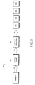
- Hybrid ARQ protocol An example of Hybrid ARQ protocol is shown in FIG. 6 .
- receiver 140 After receiving the first subpacket SP1 from transmitter 130, receiver 140 tries to decode the received information packet. In case of unsuccessful decoding, receiver 140 stores SP1 and sends a Negative Acknowledgement (NACK) signal to transmitter 130. After receiving the NACK signal, transmitter 130 transmits the second subpacket SP2. After receiving the second subpacket SP2, receiver 140 combines SP2 with the previously received subpacket SP1, and tries to jointly decode the combined information packet. At any point, if the information packet is successfully decoded by indication of a successful Cyclic Redundancy Check (CRC) check, for example, receiver 140 sends an ACK signal to transmitter 130.
- CRC Cyclic Redundancy Check
- the information packet is successfully decoded after receiving and combining three subpackets, SP1, SP2 and SP3.
- the ARQ protocol shown in FIG. 6 is generally referred to as stop-and-wait protocol because the transmitter waits for the ACK/NACK signal before sending the next subpacket. After receiving the ACK signal, the transmitter can move on to transmit a new information packet to the same or a different user.
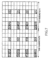
- the downlink reference signals mapping for four transmission antennas in the 3GPP LTE (3 rd Generation Partnership Project Long Term Evolution) system is shown in FIG. 7 .
- the notation R p is used to denote a resource element used for reference signal transmission on antenna port p. It can be noted that density on antenna ports 2 and 3 is half the density on antenna ports 0 and 1. This leads to weaker channel estimates on antenna ports 2 and 3 relative to channel estimates on antenna ports 0 and 1.
- Multiple Fourier matrices can be defined by introducing a shift parameter (g/G) in the Fourier matrix.
- a Hadamard matrix of order n is a solution to Hadamard's matrimum determinant problem.
- each matrix A and B is an Alamouti code for the pair of symbols S 1 and S 2 , and the pair of symbols S 3 and S 4 , respectively.
- the operator .* formed by a period immediately followed by an asterisk denotes element-wise multiplication and ⁇ denotes kronecker product.
- the Fourier matrix P 2 2 can be used to generate the following 4x4 transmission matrix.
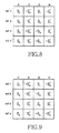
- FIG. 8 is an illustration of the transmission diversity scheme for four transmission antennas and four time slots according to Equation (25) in the first embodiment of the principles of the present invention.
- the same principle can be applied to the case where the 4x4 matrix transmission is over a mix of subcarriers and time slots.
- the four elements (index n) can be constructed with 2 subcarriers and 2 time slots.
- T i,r is useful for evening out pilot-density disparity inherent in the reference signal structure of the LTE system.
- T 0 ,r is given by the following.
- T 0 , r 1 4 ⁇ S 1 - S 2 * S 1 - S 2 * S 3 - S 4 * - S 3 S 4 * S 2 S 1 * S 2 S 1 * S 4 S 3 * - S 4 - S 3 *
- FIG. 9 is an illustration of the transmission diversity scheme for four transmission antennas and four time slots according to Equation (27) in the second embodiment of the principles of the present invention.
- Equation (8) we propose to exchange the second and the third row of the SFBC-FSTD matrix as shown in Equation (8), thus resulting in new SFBC matrix.
- symbols S 1 and S 2 are transmitted over antennas ports 0 and 2 while symbols S 3 and S 4 are transmitted over antenna ports 1 and 3 as given by the transmit matrix below. Again, this is useful for evening out pilot-density disparity inherent in the reference signal structure of the LTE system.
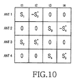
- FIG. 10 is an illustration of the transmission diversity scheme for four transmission antennas and four time slots according to Equation (28) as in the third embodiment of the principles of the present invention.
- T 2 is used for the first transmission at the first time slot (slot 1) and T 2,h is used for the second transmission at the fifth time slot (slot 5).
- T i is used for the first transmission at the first time slot (slot 1)
- T i,h is used for the second transmission at the fifth time slot (slot 5).
- symbols (S 1 , S 2 ) are transmitted via antenna 1 and 2 for the first transmission and antennas 3 and 4 when repeated for the second transmission.
- symbols (S 3 , S 4 ) are transmitted via antenna 3 and 4 for the first transmission and antennas 1 and 2 when repeated for the second transmission.
- T i A 1 0 0 0 1 0 0 0 0 1 0 0 0 1 ⁇ T i
- T i B 1 0 0 0 0 0 1 0 0 1 0 0 0 0 0 1 ⁇ T i
- T i E 0 1 0 0 0 0 0 0 0 1 1 0 0 0 0 0 1 0
- T 0 A 1 4 ⁇ S 1 - S 2 * S 1 - S 2 * S 2 S 1 * S 2 S 1 * S 3 - S 4 * - S 3 S 4 * S 4 S 3 * - S 4 - S 3 *
- T 0 B 1 4 ⁇ S 1 - S 2 * S 1 - S 2 * S 3 - S 4 * - S 3 S 4 * S 2 S 1 * S 2 S 1 * S 4 S 3 * - S 4 - S 3 *
- the transmitter maps the modulated symbols to the physical time-frequency OFDM transmission resource
- the transmitter selects a subset of K permuted matrices from the six permuted matrices for a given number i.
- the transmitter divides the OFDM transmission resource into K parts in frequency domain, each uses a selected permuted matrix from the subset of K matrices.
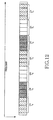
- These three matrices will applied along the frequency dimension, in a pattern that repeats every 12 sub-carriers, as shown in FIG. 12 .
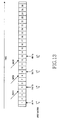
- the transmitter transmits the same four modulated symbols by using T 0 C via four subcarriers in time slot 3. Noteworthy, this approach of applying permuted SFBC matrices on retransmissions apply to both Chase Combining and incremental redundancy.
- a seventh embodiment according to the principles of the current invention, the application of permuted matrices in frequency dimension, and the application of the permuted matrices in time dimension over several HARQ retransmissions, are combined.
- row-permuted matrices T 0 A , T 0 B and T 0 C in frequency dimension may be used for different sub-carriers during each retransmission.
- row-permuted matrices T 0 A , T 0 B and T 0 C in frequency dimension are used for different sub-carriers; in a second time slot, row-permuted matrices T 0 D , T 0 E and T 0 F are used for the corresponding sub-carriers.
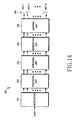
- FIG. 14 is an illustration of a transmitter constructed as an exemplary embodiment according to the principles of the present invention.
- Transmitter 200 is constructed with a modulator 210, a precoding unit 220, a spreading unit 230, a permutation unit 240, a mapping unit 250 and a plurality of antennas 240.
- Modulator 210 modulates data to be transmitted into a plurality of modulated symbols.
- Precoding unit 220 encodes each subset of modulated symbols from among said plurality of symbols in accordance with a transmission diversity scheme to result in a plurality of N by N matrices.
- each N by N matrix corresponds to each subset of N modulated symbols.
- Spreading unit 230 orthogonally spreads the plurality of N by N matrices to generate an output matrix.
- Permutation unit 240 generates several row-permuted matrices based upon the output matrix.
- Mapping unit 250 maps the symbols in the row-permuted matrices into a plurality of resource elements.
- the symbols in the row-permuted matrices is transmitted through the plurality of antennas 260 by using either a space time transmission diversity scheme, a space frequency transmission diversity scheme, or a combination of a space time transmission diversity scheme and a space frequency transmission diversity scheme.
- the invention provides the following further twenty-six aspects counted from one.
- the method according to the first aspect with the first output matrix being generated by: generating an M by M spreading matrix which is a Kronecker product of an N by N orthogonally spreading matrix and an X by X matrix with all elements being 1; and orthogonally spreading the first M by M code matrix by an element-wise multiplication of the M by M code matrix and the M by M spreading matrix.
- the method according to the first aspect further comprising: exchanging a selected pair of rows within the first output matrix before transmitting the symbols in the first output matrix; and exchanging a selected pair of rows within the second output matrix before transmitting the symbols in the first output matrix.
- the method according to the first aspect further comprising: exchanging a selected pair of columns within the first output matrix before transmitting the symbols in the first output matrix; and exchanging a selected pair of columns within the second output matrix before transmitting the symbols in the first output matrix.
- the method according to the twelfth aspect with the transmission diversity scheme being an Alamouti diversity scheme.
- the method according to the twelfth aspect with the output matrix being generated by: generating an M by M spreading matrix which is a Kronecker product of an N by N orthogonally spreading matrix and an X by X matrix with all elements being 1; and orthogonally spreading the M by M code matrix by an element-wise multiplication of the M by M code matrix and the M by M spreading matrix.
- the method according to the twelfth aspect further comprising transmitting the symbols in the selected K row-permuted matrices using the corresponding subcarriers via the plurality of antennas in a subsequent time slot.
- the method according to the seventeenth aspect with the transmission diversity scheme being an Alamouti diversity scheme.
- the method according to the seventeenth aspect with the output matrix being generated by: generating an M by M spreading matrix which is a Kronecker product of an N by N orthogonally spreading matrix and an X by X matrix with all elements being 1; and orthogonally spreading the M by M code matrix by an element-wise multiplication of the M by M code matrix and the M by M spreading matrix.
- a 1 through A x are the plurality of N by N matrices
- X is the number of the plurality of N by N matrices
- M N ⁇ X; orthogonally spreading the M by M code matrix to generate an output matrix; generating a set of row
- a transmitter for transmitting data comprising: a modulator modulating data to be transmitted into a plurality of modulated symbols; a precoding unit dividing the plurality of modulated symbols into a plurality of subsets, and encoding each subset of modulated symbols from among said plurality of symbols in accordance with a transmission diversity scheme to result in a plurality of N by N matrices, with each N by N matrix corresponding to each pair of modulated symbols; a spreading unit orthogonally spreading the plurality of N by N matrices to generate an output matrix; a permutation unit for permuting at least one pair of rows in the output matrix to generate a plurality of row-permuted matrices; a mapping unit for mapping the symbols in the plurality of row-permuted matrices into available transmission resources; and a plurality of antennas for transmitting the symbols in the plurality of row-permuted matrices.
- the transmitter according to the twenty-second aspect comprised of the mapping unit mapping the symbols in a selected subset of the plurality of row-permuted matrices into available transmission resources.
- the transmitter according to the twenty-second aspect comprised of the mapping unit repeatedly mapping the symbols in a selected subset of the plurality of row-permuted matrices into a plurality of frequency sub-carriers of the transmission resources.
- the transmitter according to the twenty-second aspect comprised of the mapping unit repeatedly mapping the symbols in a selected subset of the plurality of row-permuted matrices into a plurality of time slots of the transmission resources.
- the transmitter according to the twenty-second aspect comprised of the transmitter transmitting the symbols in the plurality of row-permuted matrices in response to a negative acknowledgement signal received from a receiver.
Landscapes
- Engineering & Computer Science (AREA)
- Computer Networks & Wireless Communication (AREA)
- Signal Processing (AREA)
- Physics & Mathematics (AREA)
- Spectroscopy & Molecular Physics (AREA)
- Power Engineering (AREA)
- Radio Transmission System (AREA)
- Mobile Radio Communication Systems (AREA)
Abstract
Description
- The present invention relates to a method for transmitting data in a communication system, and more specifically, a process and circuits for transmitting information using multiple antennas transmission diversity scheme.
- A typical cellular radio system includes a number of fixed base stations and a number of mobile stations. Each base station covers an geographical area, which is defined as a cell.
- Typically, a non-line-of-sight (NLOS) radio propagation path exists between a base station and a mobile station due to natural and man-made objects disposed between the base station and the mobile station. As a consequence, radio waves propagate while experiencing reflections, diffractions and scattering. The radio wave which arrives at the antenna of the mobile station in a downlink direction, or at the antenna of the base station in an uplink direction, experiences constructive and destructive additions because of different phases of individual waves generated due to the reflections, diffractions, scattering and out-of-phase reccombination. This is due to the fact that, at high carrier frequencies typically used in a contemporary cellular wireless communication, small changes in differential propagation delays introduces large changes in the phases of the individual waves. If the mobile station is moving or there are changes in the scattering environment, then the spatial variations in the amplitude and phase of the composite received signal will manifest themselves as the time variations known as Rayleigh fading or fast fading attributable to multipath reception. The time-varying nature of the wireless channel require very high signal-to-noise ratio (SNR) in order to provide desired bit error or packet error reliability.
- The scheme of diversity is widely used to combat the effect of fast fading by providing a receiver with multiple faded replicas of the same information-bearing signal.
- The schemes of diversity in general fall into the following categories: space, angle, polarization, field, frequency, time and multipath diversity. Space diversity can be achieved by using multiple transmit or receive antennas. The spatial separation between the multiple antennas is chosen so that the diversity branches, i.e., the signals transmitted from the multiple antennas, experience fading with little or no correlation. Transmit diversity, which is one type of space diversity, uses multiple transmission antennas to provide the receiver with multiple uncorrelated replicas of the same signal. Transmission diversity schemes can further be divided into open loop transmit diversity and closed-loop transmission diversity schemes. In the open loop transmit diversity approach no feedback is required from the receiver. In one type of closed loop transmit diversity, a receiver knows an arrangement of transmission antennas, computes a phase and amplitude adjustment that should be applied at the transmitter antennas in order to maximize a power of the signal received at the receiver. In another arrangement of closed loop transmit diversity referred to as selection transmit diversity (STD), the receiver provides feedback information to the transmitter regarding which antenna(s) to be used for transmission.
- An example of open-loop transmission diversity scheme is the Alamouti 2 × 1 space-time diversity scheme. The Alamouti 2 × 1 space-time diversity scheme contemplates transmitting a Alamouti 2 × 2 block code using two transmission antennas using either two time slots (i.e., Space Time Block Code (STBC) transmit diversity) or two frequency subcarriers (i.e., Space Frequency Block Code (SFBC) transmit diversity).
- One limitation of Alamouti 2 × 1 space-time diversity scheme is that this scheme can only be applied to two transmission antennas. In order to transmit data using four transmission antennas, a Frequency Switched Transmit Diversity (FSTD) or a Time Switched Transmit Diversity (TSTD) is combined with block codes. In case of combined SFBC+FSTD scheme or STBC+TSTD scheme, the matrix of the transmitted symbols from the four transmission antennas may be given as:

- The problem with combined SFBC+FSTD scheme and STBC+TSTD schemes is that only a fraction of the total transmission antennas and hence power amplifier capability is used for transmission in a given frequency or time resource. This is indicated by '0' elements in the SFBC+FSTD and STBC+TSTD matrix given above. When the transmit power on the non-zero elements in the matrix is increased, bursty interference is generated to the neighboring cells degrading system performance. Generally, bursty interference manifests itself when certain phases of a frequency hopping pattern incur more interference than other phases.
- It is therefore an object of the present invention to provide an improved method and transmitter circuit for transmitting data via multiple antennas.
- It is another object to provide a method and transmitter circuit for transmitting data using multiple antennas transmission diversity scheme.
- According to one aspect of the present invention, a method for data transmission contemplates modulating data to be transmitted into a plurality of modulated symbols, dividing the plurality of modulated symbols into a plurality of subsets of modulated symbols, with each subset having N modulated symbols, and N being an integer no smaller than 2, encoding each subset of modulated symbols in accordance with a transmission diversity scheme to produce a plurality of N by N matrices, with each N by N matrix corresponding to each pair of modulated symbols, generating a first M by M code matrix comprised of the plurality of N by N matrices, orthogonally spreading the first M by M code matrix to generate a first output matrix, and transmitting the symbols in the first output matrix via a plurality of antennas in a first time slot.
- The method may further include exchanging a selected pair of rows in the first M by M code matrix to generate a second M by M code matrix, orthogonally spreading the second M by M code matrix to generate a second output matrix, and transmitting the symbols in the second output matrix via the plurality of antennas in a second time slot.
- The transmission diversity scheme may be an Alamouti diversity scheme, and each of the N by N matrices may be established by:


where A1 through Ax are the plurality of N by N matrices, X is the number of the plurality of N by N matrices, and M = N × X. - The orthogonal spreading of the plurality of N by N matrices being performed according to a Fourier matrix, and each element of the Fourier matrix being established by:

where m, n = 0, 1, ... (N-1), G=N×N, m is the row number of the matrix, n is the column number of the matrix, and g is selected to be any number between 0 and G-1. - Alternatively, the orthogonal spreading of the plurality of N by N matrices being performed according to a Zadoff-Chu sequence, and an n-th entry ck(n) of a k-th Zadoff-Chu sequence being established by:


where k is an integer which is relatively prime with L, and q is an integer. - Still alternatively, the orthogonal spreading of the plurality of N by N matrices being performed according to a Hadamard matrix, and a Hadamard matrix of order n being established by:

where In is an n × n identity matrix. - The first output matrix may be generated by generating an M by M spreading matrix which is a Kronecker product of an N by N orthogonally spreading matrix and an X by X matrix with all elements being 1, and orthogonally spreading the first M by M code matrix by an element-wise multiplication of the M by M code matrix and the M by M spreading matrix.
- The symbols in the second output matrix may be transmitted in response to a negative acknowledgement signal received from a receiver.
- The method may further include generating a set of row-permuted matrixes based upon the first output matrix, each row-permuted matrix being generated by exchanging a selected pair of rows in the output matrix, segregating the available transmission resource into a plurality of frequency sub-carriers, dividing the plurality of sub-carriers into a plurality of subsets of continuous subcarriers, each subset of sub-carriers comprising M sub-carriers, selecting a subset of K row-permuted matrices to be mapped into the transmission resources, repeatedly mapping the selected set of K row-permuted matrices into the plurality of sets of sub-carriers, with each set of M sub-carriers corresponding to a row-permuted matrix, and transmitting the symbols in the selected row-permuted matrices using the corresponding sub-carriers via a plurality of antennas.
- The method may further include generating a set of row-permuted matrixes based upon the first output matrix, each row-permuted matrix being generated by exchanging a selected pair of rows in the output matrix, selecting a subset of K row-permuted matrices, and transmitting the symbols in the selected subset of row-permuted matrices in different time slots, with the symbols in each row-permuted matrix being transmitted in one time slot.
- The method may further include generating a set of row-permuted matrixes based upon the first output matrix, each row-permuted matrix being generated by exchanging a selected pair of rows in the output matrix, selecting a subset of K row-permuted matrices, segregating available transmission resources into a plurality of frequency sub-carriers, dividing the plurality of sub-carriers into a plurality of sets of continuous sub-carriers, each set of sub-carriers comprising M sub-carriers, selecting a subset of K row-permuted matrices to be mapped into the transmission resources, repeatedly mapping the selected set of K row-permuted matrices into the plurality of sets of sub-carriers, with each set of M sub-carriers corresponding to a row-permuted matrix, and transmitting the symbols in the selected row-permuted matrices using the corresponding subcarriers via a plurality of antennas in different time slots.
- According to another aspect of the present invention, a transmitter is constructed with a modulator modulating data to be transmitted into a plurality of modulated symbols, a precoding unit dividing the plurality of modulated symbols into a plurality of subsets, and encoding each subset of modulated symbols from among said plurality of symbols in accordance with a transmission diversity scheme to result in a plurality of N by N matrices, with each N by N matrix corresponding to each pair of modulated symbols, a spreading unit orthogonally spreading the plurality of N by N matrices to generate an output matrix, a permutation unit for permuting at least one pair of rows in the output matrix to generate a plurality of row-permuted matrices, a mapping unit for mapping the symbols in the plurality of row-permuted matrices into available transmission resources, and a plurality of antennas for transmitting the symbols in the plurality of row-permuted matrices.
- A more complete appreciation of the invention, and many of the attendant advantages thereof, will be readily apparent as the same becomes better understood by reference to the following detailed description when considered in conjunction with the accompanying drawings in which like reference symbols indicate the same or similar components, wherein:
-
FIG. 1 is an illustration of an Orthogonal Frequency Division Multiplexing (OFDM) transceiver chain suitable for the practice of the principles of the present inventions; -
FIG. 2 is an illustration of a Space Time Block Code transmission diversity scheme for two transmission antennas; -
FIG. 3 is an illustration of a Space Frequency Block Code transmission diversity scheme for two transmission antennas; -
FIG. 4 is an illustration of an alternative Space Frequency Block Code transmission diversity scheme for two transmission antennas; -
FIG. 5 is an illustration of a transmitter in Hybrid Repeat reQuest scheme; -
FIG. 6 is an illustration of Hybrid Repeat reQuest scheme; -
FIG. 7 is an illustration of mapping of downlink reference signals in a contemporary 3rd Generation Partnership Project Long Term Evolution system; -
FIG. 8 is an illustration of a transmission diversity scheme for four transmission antennas according to a first embodiment of the principles of the present invention; -
FIG. 9 is an illustration of a transmission diversity scheme for four transmission antennas according to a second embodiment of the principles of the present invention; -
FIG. 10 is an illustration of a transmission diversity scheme for four transmission antennas according to a third embodiment of the principles of the present invention; -
FIG. 11 is an illustration of a transmission diversity scheme for four transmission antennas according to a fourth embodiment of the principles of the present invention; -
FIG. 12 is an illustration of a transmission diversity scheme for four transmission antennas according to a fifth embodiment of the principles of the present invention; -
FIG. 13 is an illustration of a transmission diversity scheme for four transmission antennas according to a sixth embodiment of the principles of the present invention; and -
FIG. 14 is an illustration of a transmitter constructed as an exemplary embodiment according to the principles of the present invention. - The present invention will be described more fully hereinafter with reference to the accompanying drawings, in which preferred embodiments of the invention are shown. As those skilled in the art would realize, the described embodiments may be modified in various different ways, all without departing from the spirit or scope of the present invention.
-
FIG. 1 illustrates an Orthogonal Frequency Division Multiplexing (OFDM) transceiver chain. In a communication system using OFDM technology, attransmitter chain 110, control signals ordata 111 is modulated bymodulator 112 and is serial-to-parallel converted by Serial/Parallel (S/P)converter 113. Inverse Fast Fourier Transform (IFFT)unit 114 is used to transfer the signal from frequency domain to time domain. Cyclic prefix (CP) or zero prefix (ZP) is added to each OFDM symbol byCP insertion unit 116 to avoid or mitigate the impact due to multipath fading. Consequently, the signal is transmitted by transmitter (Tx) frontend processing unit 117, such as an antenna (not shown), or alternatively, by fixed wire or cable. Atreceiver chain 120, assuming perfect time and frequency synchronization are achieved, the signal received by receiver (Rx) frontend processing unit 121 is processed byCP removal unit 122. Fast Fourier Transform (FFT)unit 124 transfers the received signal from time domain to frequency domain for further processing. - The total bandwidth in an OFDM system is divided into narrowband frequency units called subcarriers. The number of subcarriers is equal to the FFT/IFFT size N used in the system. In general, the number of subcarriers used for data is less than N because some subcarriers at the edge of the frequency spectrum are reserved as guard subcarriers. In general, no information is transmitted on guard subcarriers.
- The scheme of diversity is widely used to combat the effect of fast fading by providing a receiver with multiple faded replicas of the same information-bearing signal. An example of open-loop transmission diversity scheme is the Alamouti 2x1 space-time block code (STBC) transmission diversity scheme as illustrated in
FIG. 2 . In this approach, during any symbol period, i.e., time period, a transmitter transmits two data symbols via two transmission antennas to a receiver. As shown inFIG. 2 , during the first symbol interval t1, symbols S1 and S2 are respectively transmitted viaantennas ANT 1 andANT 2. During the next symbol period t2, symbols -S*2 and S*1 are respectively transmitted viaantennas ANT 1 andANT 2, where x* represents complex conjugate of x. After receiving the signals, the receiver performs a plurality of processes to recover original symbols S1 and S2. Note that the instantaneous channel gains g1 and g2 forANT 1 andANT 2, respectively, are required for processing at the receiver. Therefore, the transmitter needs to transmit separate pilot symbols via both theantennas ANT 1 andANT 2 for channel gain estimation at the receiver. The diversity gain achieved by Alamouti coding is the same as that achieved in Maximum Ratio Combining (MRC). - The 2x1 Alamouti scheme can also be implemented in a space-frequency block code (SFBC) transmission diversity scheme as illustrated in
FIG. 3 . As shown inFIG. 3 , symbols S1 and S2 are respectively transmitted to a receiver viaantennas ANT 1 andANT 2 on a first subcarrier having frequency f1 in an Orthogonal Frequency Division Multiplexing (OFDM) system, symbols -S* 2 and S*1 are respectively transmitted viaantennas ANT 1 andANT 2 on a second subcarrier having frequency f2. Therefore a matrix of transmitted symbols fromantennas ANT 1 andANT 2 can be written as:
- The received signal at the receiver on subcarrier having frequency f1 is r1 , and the received signal at the receiver on subcarrier having frequency f2 is r2 . r1 and r2 can be written as:

where h1 and h2 are channel gains fromANT 1 andANT 2 respectively. We also assume that the channel from a given antennas does not change between subcarrier having frequency f1 and subcarrier having frequency f2 . The receiver performs equalization on the received signals and combines the two received signals (r1 and r 2) to recover the symbols S1 and S2 . The recovered symbols Ŝ1 and Ŝ2 can be written as:
- It can be seen that both of the transmitted symbols Ŝ1 and Ŝ2 achieve full spatial diversity, that is, the each of the transmitted symbols Ŝ1 and Ŝ2 completely removes an interference from the other one.
- An alternative mapping for two transmission antennas SFBC scheme is shown in
FIG. 4 . A matrix of transmitted symbols fromantennas ANT 1 andANT 2 can be written as:
- The transmit matrix in Equation (5) for the scheme in
FIG. 4 is a transpose of the transmit matrix in Equation (2) for the scheme shown inFIG. 3 . - For the case of four transmission antennas, orthogonal full-diversity block codes are not available. An example of quasi-orthogonal block code, also known as ABBA code, is given below.

where T ij represents symbol transmitted on the ith antenna and the jth subcarrier or jth time slot (i=1,2,3,4, j=1,2,3,4) for the case of 4-Tx antennas. A and B are block codes given as below.
- The problem with quasi-orthogonal block codes is that the loss of orthogonality may result in inter-symbol interference and hence may degrade system performance and throughput.
- Other proposals found in the art for four transmission antennas transmit diversity combines Frequency Switched Transmit Diversity (FSTD) or Time Switched Transmit Diversity (TSTD) with block codes. In case of combined SFBC+FSTD scheme or STBC+TSTD scheme, the matrix of the transmitted symbols from the four transmission antennas may be given as:

- An equivalent representation of the above SFBC+FSTD transmit signal given in equation (1) exists in the following form. Let the transmit signal vector y(i) = [y (0)(i) y (1)(i) y (2)(i) y (3)(i)] T denote the transmit signal vector on four transmit antennas for the ith subcarrier. The transmit signal generated from the SFBC+FSTD scheme in (1) can be equivalently written as follows, assuming the transmit signal is mapped to the four consecutive subcarriers 4i, 4i+1,4i+1,4i+3:

where each of S1(i), S2(i), S3(i), S4(i) is a functions of index i. - The problem with combined SFBC+FSTD scheme and STBC+TSTD schemes is that only a fraction of the total transmission antennas and hence power amplifier (PA) capability is used for transmission in a given frequency or time resource. This is indicated by '0' elements in the SFBC+FSTD and STBC+TSTD matrix given above. When the transmit power on the non-zero elements in the matrix is increased, bursty interference is generated to the neighboring cells degrading system performance.
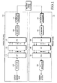
- Hybrid Automatic Repeat request (ARQ) is a retransmission scheme whereby a transmitter sends redundant coded information (i.e., subpackets) in small increments. As shown in
FIG. 5 , intransmitter 130, an information packet P is first input intochannel coder 131 to perform channel coding. The resulted coded bit stream is input intosubpacket generator 132 to break into smaller units, i.e., subpackets SP1, SP2, SP3 and SP4. The hybrid ARQ retransmissions can either contain redundant symbols or coded bits which are different than the previous transmission(s) or copies of the same symbols or coded bits. The scheme which retransmits copies of the same information is referred to as chase combining. In case of Chase combining, the subpackets SP1, SP2, SP3 and SP4 as shown inFigure 4 are all identical. The scheme where retransmitted symbols or coded bits are different than the previous transmission is generally referred to as an incremental redundancy scheme. - An example of Hybrid ARQ protocol is shown in
FIG. 6 . After receiving the first subpacket SP1 fromtransmitter 130,receiver 140 tries to decode the received information packet. In case of unsuccessful decoding,receiver 140 stores SP1 and sends a Negative Acknowledgement (NACK) signal totransmitter 130. After receiving the NACK signal,transmitter 130 transmits the second subpacket SP2. After receiving the second subpacket SP2,receiver 140 combines SP2 with the previously received subpacket SP1, and tries to jointly decode the combined information packet. At any point, if the information packet is successfully decoded by indication of a successful Cyclic Redundancy Check (CRC) check, for example,receiver 140 sends an ACK signal totransmitter 130. In the example ofFIG. 6 , the information packet is successfully decoded after receiving and combining three subpackets, SP1, SP2 and SP3. The ARQ protocol shown inFIG. 6 is generally referred to as stop-and-wait protocol because the transmitter waits for the ACK/NACK signal before sending the next subpacket. After receiving the ACK signal, the transmitter can move on to transmit a new information packet to the same or a different user. - The downlink reference signals mapping for four transmission antennas in the 3GPP LTE (3rd Generation Partnership Project Long Term Evolution) system is shown in
FIG. 7 . The notation Rp is used to denote a resource element used for reference signal transmission on antenna port p. It can be noted that density onantenna ports antenna ports antenna ports antenna ports - In the current invention we describe an open-loop transmission diversity scheme where Alamouti block code is spread with an orthogonal function to provide diversity for transmissions via more than two transmission antennas. We will describe the invention assuming a Fourier matrix. It should be noted that the principles of the current invention can be easily extended and applied to the cases of other orthogonal functions such as Hadamard function or Zadoff-Chu (ZC) sequences.
- A Fourier matrix is a N xN square matrix with entries given by:

- For example, a 2x2 Fourier matrix can be expressed as:

- Similarly, a 4x4 Fourier matrix can be expressed as:

- Multiple Fourier matrices can be defined by introducing a shift parameter (g/G) in the Fourier matrix. The entry of the multiple Fourier matrices is given by:

- A set of four 2x2 Fourier matrices can be defined by taking G=4, and g=0, 1, 2 and 3 are written as:


- Note that in addition to the set of four Fourier matrices listed above, we can also apply row or column permuted versions of these set of Fourier matrices. For example, the row and column permutations of the matrix P 2 0 is given by:

- For each Fourier matrix, there are two permuted versions. So the total number of the spread matrix P is 12.
- In a k-th Zadoff-Chu sequence, an n-th entry ck(n) of the k-th Zadoff-Chu sequence can be expressed as:

- A Hadamard matrix of order n is a solution to Hadamard's matrimum determinant problem. An equivalent definition of the Hadamard matrices is given by:

where In is an n × n identity matrix. - For example, a Hadamard matrix of
order 4 can be expresses as:
- In a first embodiment according to the principles of the present invention, we assume that four symbols S1 , S2 , S3 and S4 are transmitted on four subcarriers using four transmission antennas. Let us define matrix A and B as below.

- It can be seen that each matrix A and B is an Alamouti code for the pair of symbols S1 and S2 , and the pair of symbols S3 and S4 , respectively. We construct a 2 x 2 matrix with A and B as its elements and perform an element-by-element multiplication with an expanded 2 x 2 Fourier matrix as below. Note that the operator .* formed by a period immediately followed by an asterisk denotes element-wise multiplication and ⊗ denotes kronecker product.

- For i = 0 case, the resulting 4x4 matrix denoting discrete Fourier transform DFT-spread SFBC or DFT-spread STBC is given as below.

- Similarly, for i=2 case, the Fourier matrix P 2 2 can be used to generate the following 4x4 transmission matrix.

- For the case where the spreading matrix is a permuted version of the Fourier matrix, for example, for i=5, we have

- For a given matrix (for example matrix T 0), the element on row m, column n is denoted by [T 0] m,n, and [T 0] m,n represents the symbol transmitted on the mth antenna and the nth subcarrier or nth time slot, m = 1,2,3,4 and n = 1,2,3,4 for the case of four transmission antennas.
FIG. 8 is an illustration of the transmission diversity scheme for four transmission antennas and four time slots according to Equation (25) in the first embodiment of the principles of the present invention. - It can be noted that the same principle can be applied to the case where the 4x4 matrix transmission is over a mix of subcarriers and time slots. For example, the four elements (index n) can be constructed with 2 subcarriers and 2 time slots.
- In a second embodiment according to the principles of the present invention, we exchange the second row and the third row of Ti , thus resulting in a new SFBC matrix called Ti,r. Ti,r is useful for evening out pilot-density disparity inherent in the reference signal structure of the LTE system. For example, T 0,r is given by the following.

-
FIG. 9 is an illustration of the transmission diversity scheme for four transmission antennas and four time slots according to Equation (27) in the second embodiment of the principles of the present invention. - In a third embodiment according to the principles of the present invention, we propose to exchange the second and the third row of the SFBC-FSTD matrix as shown in Equation (8), thus resulting in new SFBC matrix. By this operation, symbols S1 and S2 are transmitted over
antennas ports antenna ports 
-
FIG. 10 is an illustration of the transmission diversity scheme for four transmission antennas and four time slots according to Equation (28) as in the third embodiment of the principles of the present invention. - In a fourth embodiment according to the principles of the current invention, the matrices A and B are permuted for Hybrid ARQ retransmissions or repeated symbols as below:

- This allows for achieving full diversity when the symbols are repeated either due to lower coding rate or Hybrid ARQ retransmissions as shown in
FIG. 11 , where T 2 is used for the first transmission at the first time slot (slot 1) and T 2,h is used for the second transmission at the fifth time slot (slot 5). Similarly, any pairs of Ti, Ti,h for i=0,...,3 can be used for HARQ purpose. This is because symbols (S1, S2) are transmitted viaantenna antennas antenna antennas - In a fifth embodiment according to the principles of the current invention, we define a set of totally six row-permuted matrices for each matrix Ti defined as above, for i=0,...,3. Note other row-permutation are possible but is equivalent to these six included here. These six permuted matrices are denoted as Ti A ,Ti B ,Ti C ,Ti D ,Ti E ,Ti F and are defined as (for i=0,...,3)

- For example, the six row-permuted versions of T 0 are given by

- While the transmitter maps the modulated symbols to the physical time-frequency OFDM transmission resource, the transmitter selects a subset of K permuted matrices from the six permuted matrices for a given number i. Afterward, the transmitter divides the OFDM transmission resource into K parts in frequency domain, each uses a selected permuted matrix from the subset of K matrices. One example is to let i=0, K=3, and let the three permuted matrices be T 0 A ,T 0 B ,T 0 C . These three matrices will applied along the frequency dimension, in a pattern that repeats every 12 sub-carriers, as shown in
FIG. 12 . - In a sixth embodiment according to the principles of the current invention, the base station selects a subset of K permuted matrices for the purpose of HARQ. Furthermore, the base station applied different permuted matrices within this subset on different retransmissions of the packet, as illustrated in
FIG. 13 , where a subset of three (K = 3) matrices are chosen for HARQ retransmissions. Specifically, attime slot 1, the transmitter transmits four modulated symbols by using T0 A via four subcarriers. In response to a NACK signal, the transmitter transmit the same four modulated symbols by using T0 B via four subcarriers intime slot 2. Again, in response to another NACK signal, the transmitter transmits the same four modulated symbols by using T0 C via four subcarriers intime slot 3. Noteworthy, this approach of applying permuted SFBC matrices on retransmissions apply to both Chase Combining and incremental redundancy. - In a seventh embodiment according to the principles of the current invention, the application of permuted matrices in frequency dimension, and the application of the permuted matrices in time dimension over several HARQ retransmissions, are combined. For example, row-permuted matrices T0 A, T0 B and T0 C in frequency dimension may be used for different sub-carriers during each retransmission. Alternatively, in a first time slot, row-permuted matrices T0 A, T0 B and T0 C in frequency dimension are used for different sub-carriers; in a second time slot, row-permuted matrices T0 D, T0 E and T0 F are used for the corresponding sub-carriers.
-
FIG. 14 is an illustration of a transmitter constructed as an exemplary embodiment according to the principles of the present invention.Transmitter 200 is constructed with amodulator 210, aprecoding unit 220, a spreadingunit 230, apermutation unit 240, amapping unit 250 and a plurality ofantennas 240.Modulator 210 modulates data to be transmitted into a plurality of modulated symbols.Precoding unit 220 encodes each subset of modulated symbols from among said plurality of symbols in accordance with a transmission diversity scheme to result in a plurality of N by N matrices. Here, each N by N matrix corresponds to each subset of N modulated symbols. Spreadingunit 230 orthogonally spreads the plurality of N by N matrices to generate an output matrix.Permutation unit 240 generates several row-permuted matrices based upon the output matrix.Mapping unit 250 maps the symbols in the row-permuted matrices into a plurality of resource elements. The symbols in the row-permuted matrices is transmitted through the plurality ofantennas 260 by using either a space time transmission diversity scheme, a space frequency transmission diversity scheme, or a combination of a space time transmission diversity scheme and a space frequency transmission diversity scheme. - The invention provides the following further twenty-six aspects counted from one.
- The aspect of a method for data transmission, the method comprising the steps of: modulating data to be transmitted into a plurality of modulated symbols; dividing the plurality of modulated symbols into a plurality of subsets of modulated symbols, with each subset having N modulated symbols, and N being an integer no smaller than 2; encoding each subset of modulated symbols in accordance with a transmission diversity scheme to produce a plurality of N by N matrices, with each N by N matrix corresponding to each pair of modulated symbols; generating a first M by M code matrix comprising the plurality of N by N matrices, with M = N × X and X is the number of the plurality of N by N matrices; orthogonally spreading the first M by M code matrix to generate a first output matrix; transmitting the symbols in the first output matrix via a plurality of antennas in a first time slot; generating a second M by M code matrix by exchanging at least one selected pair of rows in the first M by M code matrix; orthogonally spreading the second M by M code matrix to generate a second output matrix; and transmitting the symbols in the second output matrix via the plurality of antennas in a second time slot.
- The method according to the first aspect, with the transmission diversity scheme being an Alamouti diversity scheme, and each of the N by N matrices being established by:

where N = 2, and S1 and S2 are one pair of the modulated symbols. - The method according to the first aspect, with the transmission diversity scheme being an Alamouti diversity scheme, and each of the N by N matrices being established by:

where N = 2, and S1 and S2 are one pair of the modulated symbols. - The method according to the first aspect, with the first M by M code matrix C being established by:

where A1 through Ax are the plurality of N by N matrices. - The method according to the first aspect, with the orthogonal spreading of the plurality of N by N matrices being performed according to a Fourier matrix, and each element of the Fourier matrix being established by:

where m, n = 0, 1, ... (N-1), G=N×N, m is the row number of the matrix, n is the column number of the matrix, and g is selected to be any number between 0 and G-1. - The method according to the first aspect, with the orthogonal spreading of the plurality of N by N matrices being performed according to a Zadoff-Chu sequence, and an n-th entry ck(n) of a k-th Zadoff-Chu sequence being established by:


where k is an integer which is relatively prime with L, and q is an integer. - The method according to the first aspect, with the orthogonal spreading of the plurality of N by N matrices being performed according to a Hadamard matrix, and a Hadamard matrix of order n being established by:

where In is an n × n identity matrix. - The method according to the first aspect, with the first output matrix being generated by: generating an M by M spreading matrix which is a Kronecker product of an N by N orthogonally spreading matrix and an X by X matrix with all elements being 1; and orthogonally spreading the first M by M code matrix by an element-wise multiplication of the M by M code matrix and the M by M spreading matrix.
- The method according to the first aspect, further comprising: exchanging a selected pair of rows within the first output matrix before transmitting the symbols in the first output matrix; and exchanging a selected pair of rows within the second output matrix before transmitting the symbols in the first output matrix.
- The method according to the first aspect, further comprising: exchanging a selected pair of columns within the first output matrix before transmitting the symbols in the first output matrix; and exchanging a selected pair of columns within the second output matrix before transmitting the symbols in the first output matrix.
- The method according to the first aspect, with the symbols in the second output matrix being transmitted in response to a NACK signal received from a receiver.
- The aspect of a method for data transmission, the method comprising the steps of: modulating data to be transmitted into a plurality of modulated symbols; dividing the plurality of modulated symbols into a plurality of sets of M modulated symbols; for each set of M modulated symbols, generating an output matrix by: dividing the M modulated symbols into a plurality of subsets of N modulated symbols, with M = N × X, and X is the quantity of the subsets of N modulated symbols; encoding each subset of N modulated symbols in accordance with a transmission diversity scheme to produce a plurality of N by N matrices, with each N by N matrix corresponding to each subset of modulated symbols; generating an M by M code matrix comprising the plurality of N by N matrices; and orthogonally spreading the M by M code matrix to generate the output matrix; selecting a set of K output matrices from among the generated output matrices; generating a set of K row-permuted matrixes based upon the corresponding output matrix within the set of K output matrices, with each row-permuted matrix being generated by using a selected row-permutation scheme, and the row permutation schemes used by different matrices being different; segregating the available transmission resource into a plurality of frequency subcarriers; dividing the plurality of sub-carriers into a plurality of sets of M continuous sub-carriers; repeatedly mapping the selected set of K row-permuted matrices into the plurality of sets of M sub-carriers, with each set of M subcarriers corresponding to a row-permuted matrix; and transmitting the symbols in the selected row-permuted matrices using the corresponding sub-carriers via a plurality of antennas.
- The method according to the twelfth aspect, with the transmission diversity scheme being an Alamouti diversity scheme.
- The method according to the twelfth aspect, with the M by M code matrix C being established by:

where A1 through Ax are the plurality of N by N matrices. - The method according to the twelfth aspect, with the output matrix being generated by: generating an M by M spreading matrix which is a Kronecker product of an N by N orthogonally spreading matrix and an X by X matrix with all elements being 1; and orthogonally spreading the M by M code matrix by an element-wise multiplication of the M by M code matrix and the M by M spreading matrix.
- The method according to the twelfth aspect, further comprising transmitting the symbols in the selected K row-permuted matrices using the corresponding subcarriers via the plurality of antennas in a subsequent time slot.
- The aspect of a method for data transmission, the method comprising the steps of: modulating data to be transmitted into a plurality of modulated symbols; dividing the plurality of modulated symbols into a plurality of subsets of modulated symbols, with each subset having N modulated symbols, and N being an integer no smaller than 2; encoding each subset of modulated symbols in accordance with a transmission diversity scheme to produce a plurality of N by N matrices, with each N by N matrix corresponding to each subset of modulated symbols; generating a M by M code matrix C comprising the plurality of N by N matrices, with M = N × X and X is the number of the plurality of N by N matrices; orthogonally spreading the M by M code matrix to generate an output matrix; generating a set of row-permuted matrixes based upon the output matrix, each row-permuted matrix being generated by exchanging a selected pair of rows in the output matrix; selecting a subset of K row-permuted matrices; and transmitting the symbols in the selected subset of row-permuted matrices in different time slots.
- The method according to the seventeenth aspect, with the transmission diversity scheme being an Alamouti diversity scheme.
- The method according to the seventeenth aspect, with the M by M code matrix C being established by:

where A1 through Ax are the plurality of N by N matrices. - The method according to the seventeenth aspect, with the output matrix being generated by: generating an M by M spreading matrix which is a Kronecker product of an N by N orthogonally spreading matrix and an X by X matrix with all elements being 1; and orthogonally spreading the M by M code matrix by an element-wise multiplication of the M by M code matrix and the M by M spreading matrix.
- The aspect of a method for data transmission, the method comprising the steps of: modulating data to be transmitted into a plurality of modulated symbols; dividing the plurality of modulated symbols into a plurality of subsets of modulated symbols, with each subset having N modulated symbols, and N being an integer no smaller than 2; encoding each subset of modulated symbols in accordance with a transmission diversity scheme to produce a plurality of N by N matrices, with each N by N matrix corresponding to each subset of modulated symbols; generating a M by M code matrix C, with C being established by:

where A1 through Ax are the plurality of N by N matrices, X is the number of the plurality of N by N matrices, and M = N × X; orthogonally spreading the M by M code matrix to generate an output matrix; generating a set of row-permuted matrixes based upon the output matrix, each row-permuted matrix being generated by exchanging a selected pair of rows in the output matrix; selecting a subset of K row-permuted matrices; and segregating available transmission resources into a plurality of frequency sub-carriers; dividing the plurality of subcarriers into a plurality of sets of continuous sub-carriers, each set of sub-carriers comprising M sub-carriers; selecting a subset of K row-permuted matrices to be mapped into the transmission resources; repeatedly mapping the selected set of K row-permuted matrices into the plurality of sets of sub-carriers, with each set of M sub-carriers corresponding to a row-permuted matrix; and transmitting the symbols in the selected row-permuted matrices using the corresponding subcarriers via a plurality of antennas in different time slots. - The aspect of a transmitter for transmitting data, comprising: a modulator modulating data to be transmitted into a plurality of modulated symbols; a precoding unit dividing the plurality of modulated symbols into a plurality of subsets, and encoding each subset of modulated symbols from among said plurality of symbols in accordance with a transmission diversity scheme to result in a plurality of N by N matrices, with each N by N matrix corresponding to each pair of modulated symbols; a spreading unit orthogonally spreading the plurality of N by N matrices to generate an output matrix; a permutation unit for permuting at least one pair of rows in the output matrix to generate a plurality of row-permuted matrices; a mapping unit for mapping the symbols in the plurality of row-permuted matrices into available transmission resources; and a plurality of antennas for transmitting the symbols in the plurality of row-permuted matrices.
- The transmitter according to the twenty-second aspect, comprised of the mapping unit mapping the symbols in a selected subset of the plurality of row-permuted matrices into available transmission resources.
- The transmitter according to the twenty-second aspect, comprised of the mapping unit repeatedly mapping the symbols in a selected subset of the plurality of row-permuted matrices into a plurality of frequency sub-carriers of the transmission resources.
- The transmitter according to the twenty-second aspect, comprised of the mapping unit repeatedly mapping the symbols in a selected subset of the plurality of row-permuted matrices into a plurality of time slots of the transmission resources.
- The transmitter according to the twenty-second aspect, comprised of the transmitter transmitting the symbols in the plurality of row-permuted matrices in response to a negative acknowledgement signal received from a receiver.
Claims (16)
- A method for transmitting data, the method comprising the steps of:modulating data into a plurality of modulated symbols; andtransmitting the plurality of modulated symbols through a plurality of frequency sub-carriers via a plurality of antennas based on an output matrix,wherein the output matrix is generated for transmitting a first symbol and a second symbol through a first frequency sub-carrier and a second frequency subcarrier via a first antenna and a third antenna, respectively, and transmitting a third symbol and a fourth symbol through a third frequency sub-carrier and a fourth frequency sub-carrier via a second antenna and a fourth antenna, respectively, andwherein density on a resource element used for transmitting a reference signal on the third antenna and the fourth antenna is half of density on a resource element used for transmitting a reference signal on the first antenna and the second antenna.
- The method of claim 1, wherein the transmitting the plurality of modulated symbols through the plurality of frequency sub-carriers via the plurality of antennas based on the output matrix comprises:performing an Inverse Fast Fourier Transform, IFFT, operation on the plurality of modulated symbols; andinserting a Cyclic Prefix, CP, into the IFFT processed symbols and transmitting the CP inserted symbols.
- The method of claim 1, wherein the plurality of modulated symbols are transmitted via the plurality of antennas in the same time slot.
- The method of claim 1, wherein the transmitting the plurality of modulated symbols through the plurality of frequency sub-carriers via the plurality of antennas based on the output matrix comprises:transmitting the plurality of modulated symbols using an Alamouti diversity scheme via the plurality of antennas, ortransmitting the plurality of modulated symbols using a quasi-orthogonal block code scheme via the plurality of antennas, ortransmitting the plurality of modulated symbols using a Space Frequency Block Code, SFBC, scheme, a combined SFBC + Frequency Switched Transmit Diversity, FSTD, scheme, or a combined Space Time Block Code, STBC, + Time Switched Transmit Diversity, TSTD, scheme via the plurality of antennas.
- An apparatus for transmitting data, comprising:a modulator modulating data into a plurality of modulated symbols; anda transmitter for transmitting the plurality of modulated symbols through a plurality of frequency sub-carriers via a plurality of antennas based on an output matrix,wherein the output matrix is generated for transmitting a first symbol and a second symbol through a first frequency sub-carrier and a second frequency subcarrier via a first antenna and a third antenna, respectively, and transmitting a third symbol and a fourth symbol through a third frequency sub-carrier and a fourth frequency sub-carrier via a second antenna and a fourth antenna, respectively, andwherein density on a resource element used for transmitting a reference signal on the third antenna and the fourth antenna is half of density on a resource element used for transmitting a reference signal on the first antenna and the second antenna.
- The apparatus of claim 5, wherein the transmitter comprises:an Inverse Fast Fourier Transform, IFFT, unit for performing an IFFT operation on the plurality of modulated symbols;a Cyclic Prefix, CP, inserter for inserting a CP into the IFFT processed symbols; anda transmitter front end processing unit for transmitting the CP inserted symbols.
- The apparatus of claim 5, wherein the plurality of modulated symbols are transmitted via the plurality of antennas in the same time slot.
- The apparatus of claim 5, wherein the transmitter transmits the plurality of modulated symbols using an Alamouti diversity scheme via the plurality of antennas, or transmits the plurality of modulated symbols using a quasi-orthogonal block code scheme via the plurality of antennas, or transmits the plurality of modulated symbols using a Space Frequency Block Code, SFBC, scheme, a combined SFBC + Frequency Switched Transmit Diversity, FSTD, scheme, or a combined Space Time Block Code, STBC, + Time Switched Transmit Diversity, TSTD, scheme via the plurality of antennas.
- A method for receiving data, the method comprising the steps of:receiving a plurality of symbols which are transmitted through a plurality of frequency sub-carriers via a plurality of antennas based on an output matrix in a data transmission apparatus; anddemodulating the plurality of symbols,wherein the output matrix is generated for transmitting a first symbol and a second symbol through a first frequency sub-carrier and a second frequency subcarrier via a first antenna and a third antenna, respectively, and transmitting a third symbol and a fourth symbol through a third frequency sub-carrier and a fourth frequency sub-carrier via a second antenna and a fourth antenna, respectively, andwherein density on a resource element used for transmitting a reference signal on the third antenna and the fourth antenna is half of density on a resource element used for transmitting a reference signal on the first antenna and the second antenna.
- The method of claim 9, further comprising:removing a Cyclic Prefix, CP, from the plurality of symbols; andperforming a Fast Fourier Transform, FFT, operation on the CP removed symbols.
- The method of claim 9, wherein the plurality of symbols are transmitted via the plurality of antennas in the same time slot.
- The method of claim 9, wherein the data transmission apparatus transmits the plurality of modulated symbols using an Alamouti diversity scheme via the plurality of antennas, or transmits the plurality of modulated symbols using a quasi-orthogonal block code scheme via the plurality of antennas, or transmits the plurality of modulated symbols using a Space Frequency Block Code, SFBC, scheme, a combined SFBC + Frequency Switched Transmit Diversity, FSTD, scheme, or a combined Space Time Block Code, STBC, + Time Switched Transmit Diversity, TSTD, scheme via the plurality of antennas.
- An apparatus for receiving data, comprising:a receiver for receiving a plurality of symbols which are transmitted through a plurality of frequency sub-carriers via a plurality of antennas based on an output matrix in a data transmission apparatus; anda demodulator for demodulating the plurality of symbols,wherein the output matrix is generated for transmitting a first symbol and a second symbol through a first frequency sub-carrier and a second frequency subcarrier via a first antenna and a third antenna, respectively, and transmitting a third symbol and a fourth symbol through a third frequency sub-carrier and a fourth frequency sub-carrier via a second antenna and a fourth antenna, respectively, andwherein density on a resource element used for transmitting a reference signal on the third antenna and the fourth antenna is half of density on a resource element used for transmitting a reference signal on the first antenna and the second antenna.
- The apparatus of claim 13, wherein the receiver comprises:a receiver front end unit for receiving the plurality of symbols from the data transmission apparatus;a Cyclic Prefix, CP, remover for removing a CP from the plurality of symbols; anda Fast Fourier Transform, FFT, unit for performing an FFT operation on the CP removed symbols.
- The apparatus of claim 13, wherein the plurality of symbols are transmitted via the plurality of antennas in the same time slot.
- The apparatus of claim 13, wherein the data transmission apparatus transmits the plurality of modulated symbols using an Alamouti diversity scheme via the plurality of antennas, or transmits the plurality of modulated symbols using a quasi-orthogonal block code scheme via the plurality of antennas, or transmits the plurality of modulated symbols using a Space Frequency Block Code, SFBC, scheme, a combined SFBC + Frequency Switched Transmit Diversity, FSTD, scheme, or a combined Space Time Block Code, STBC, + Time Switched Transmit Diversity, TSTD, scheme via the plurality of antennas.
Applications Claiming Priority (4)
| Application Number | Priority Date | Filing Date | Title |
|---|---|---|---|
| US92402107P | 2007-04-26 | 2007-04-26 | |
| US92433807P | 2007-05-09 | 2007-05-09 | |
| US12/005,341 US8254492B2 (en) | 2007-04-26 | 2007-12-27 | Transmit diversity in a wireless communication system |
| EP08008036A EP1986384A3 (en) | 2007-04-26 | 2008-04-25 | Transmit diversity in a wireless communication system |
Related Parent Applications (1)
| Application Number | Title | Priority Date | Filing Date |
|---|---|---|---|
| EP08008036A Division EP1986384A3 (en) | 2007-04-26 | 2008-04-25 | Transmit diversity in a wireless communication system |
Publications (3)
| Publication Number | Publication Date |
|---|---|
| EP2717505A2 true EP2717505A2 (en) | 2014-04-09 |
| EP2717505A3 EP2717505A3 (en) | 2014-12-10 |
| EP2717505B1 EP2717505B1 (en) | 2018-11-07 |
Family
ID=39760551
Family Applications (2)
| Application Number | Title | Priority Date | Filing Date |
|---|---|---|---|
| EP08008036A Withdrawn EP1986384A3 (en) | 2007-04-26 | 2008-04-25 | Transmit diversity in a wireless communication system |
| EP14150146.0A Active EP2717505B1 (en) | 2007-04-26 | 2008-04-25 | Transmit diversity in a wireless communication system |
Family Applications Before (1)
| Application Number | Title | Priority Date | Filing Date |
|---|---|---|---|
| EP08008036A Withdrawn EP1986384A3 (en) | 2007-04-26 | 2008-04-25 | Transmit diversity in a wireless communication system |
Country Status (7)
| Country | Link |
|---|---|
| US (1) | US8254492B2 (en) |
| EP (2) | EP1986384A3 (en) |
| JP (2) | JP2010519844A (en) |
| KR (1) | KR20080096471A (en) |
| CN (1) | CN103152138B (en) |
| AU (1) | AU2008244895B2 (en) |
| CA (1) | CA2684078C (en) |
Families Citing this family (51)
| Publication number | Priority date | Publication date | Assignee | Title |
|---|---|---|---|---|
| CN101467376B (en) * | 2006-06-08 | 2016-06-08 | 皇家飞利浦电子股份有限公司 | A kind of method and apparatus of space-time-frequency encoding |
| KR100925436B1 (en) | 2006-10-02 | 2009-11-06 | 엘지전자 주식회사 | Method For Transmitting Control Signal Using Efficient Multiplexing |
| US8494459B2 (en) * | 2007-02-05 | 2013-07-23 | Nec Laboratories America, Inc. | Wideband codebook construction and applications |
| HUE037913T2 (en) | 2007-03-19 | 2018-09-28 | Lg Electronics Inc | Method and apparatus for transmitting/receiving resource allocation information in mobile communication system |
| KR101049138B1 (en) | 2007-03-19 | 2011-07-15 | 엘지전자 주식회사 | In a mobile communication system, an acknowledgment signal receiving method |
| US8831042B2 (en) * | 2007-03-29 | 2014-09-09 | Lg Electronics Inc. | Method of transmitting sounding reference signal in wireless communication system |
| US20080273452A1 (en) * | 2007-05-04 | 2008-11-06 | Farooq Khan | Antenna mapping in a MIMO wireless communication system |
| KR100913090B1 (en) * | 2007-06-13 | 2009-08-21 | 엘지전자 주식회사 | A method for transmitting spread-signal in a communication system |
| KR100908063B1 (en) | 2007-06-13 | 2009-07-15 | 엘지전자 주식회사 | Method of transmitting a spread signal in a mobile communication system |
| KR101380558B1 (en) | 2007-06-19 | 2014-04-02 | 엘지전자 주식회사 | Method of Transmitting Sounding Reference Signal |
| KR100900289B1 (en) | 2007-06-21 | 2009-05-29 | 엘지전자 주식회사 | A method for transmitting and receiving a control channel in the Orthogonal Frequency Division Multiplexing system |
| KR100998188B1 (en) * | 2007-07-18 | 2010-12-03 | 삼성전자주식회사 | Apparatus and method for retransmission in wireless communication termianl |
| EP2180629B1 (en) | 2007-08-14 | 2017-11-29 | LG Electronics Inc. | Method for acquiring resource region information for PHICH and method of receiving PDCCH |
| KR101430267B1 (en) * | 2007-08-14 | 2014-08-18 | 엘지전자 주식회사 | Method of Transmitting Data in a Wireless Communication System |
| KR101397039B1 (en) * | 2007-08-14 | 2014-05-20 | 엘지전자 주식회사 | Signal Transmission Method Using CDM Against The Effect Of Channel Estimation Error in Transmit Diversity System |
| KR101507785B1 (en) * | 2007-08-16 | 2015-04-03 | 엘지전자 주식회사 | A method for transmitting channel quality information in a MIMO (Multiple Input Multiple Output) system |
| KR101405974B1 (en) * | 2007-08-16 | 2014-06-27 | 엘지전자 주식회사 | Methods for transmitting codewords in multiple input multiple output system |
| US8073071B2 (en) * | 2008-01-16 | 2011-12-06 | Mitsubishi Electric Research Laboratories, Inc. | Hybrid automatic repeat requests coding in MIMO networks |
| US8179990B2 (en) * | 2008-01-16 | 2012-05-15 | Mitsubishi Electric Research Laboratories, Inc. | Coding for large antenna arrays in MIMO networks |
| WO2010015127A1 (en) | 2008-08-07 | 2010-02-11 | Huawei Technologies Co., Ltd. | Method for transmit diversity encoding |
| US20110280336A1 (en) * | 2008-09-04 | 2011-11-17 | Robert Novak | Enhanced Method for Transmitting or Retransmitting Packets |
| US20100067512A1 (en) * | 2008-09-17 | 2010-03-18 | Samsung Electronics Co., Ltd. | Uplink transmit diversity schemes with 4 antenna ports |
| US7940740B2 (en) * | 2009-02-03 | 2011-05-10 | Motorola Mobility, Inc. | Apparatus and method for communicating and processing a positioning reference signal based on identifier associated with a base station |
| US8730925B2 (en) | 2009-04-09 | 2014-05-20 | Motorola Mobility Llc | Method and apparatus for generating reference signals for accurate time-difference of arrival estimation |
| US9118386B2 (en) | 2009-04-22 | 2015-08-25 | Lg Electronics Inc. | Method and apparatus for transmitting a reference signal in a relay communication system |
| US8411554B2 (en) * | 2009-05-28 | 2013-04-02 | Apple Inc. | Methods and apparatus for multi-dimensional data permutation in wireless networks |
| US9002354B2 (en) * | 2009-06-12 | 2015-04-07 | Google Technology Holdings, LLC | Interference control, SINR optimization and signaling enhancements to improve the performance of OTDOA measurements |
| US8483707B2 (en) * | 2009-06-26 | 2013-07-09 | Motorola Mobility Llc | Wireless terminal and method for managing the receipt of position reference singals for use in determining a location |
| EP2278729A1 (en) * | 2009-06-30 | 2011-01-26 | Alcatel Lucent | Method for diversity transmission, transmitter, and receiver thereof |
| US20110039583A1 (en) * | 2009-08-17 | 2011-02-17 | Motorola, Inc. | Muting time masks to suppress serving cell interference for observed time difference of arrival location |
| KR101591136B1 (en) | 2009-09-02 | 2016-02-02 | 애플 인크. | Transmission of symbols in a mimo environment using alamouti based codes |
| US8374633B2 (en) | 2009-10-05 | 2013-02-12 | Motorola Mobility Llc | Muting indication to enable improved time difference of arrival measurements |
| US20110176440A1 (en) * | 2010-01-15 | 2011-07-21 | Motorola-Mobility, Inc. | Restrictions on autonomous muting to enable time difference of arrival measurements |
| US8509102B2 (en) * | 2010-02-24 | 2013-08-13 | Motorola Mobility Llc | Threshold determination in TDOA-based positioning system |
| US9203489B2 (en) | 2010-05-05 | 2015-12-01 | Google Technology Holdings LLC | Method and precoder information feedback in multi-antenna wireless communication systems |
| US8401105B2 (en) | 2010-06-10 | 2013-03-19 | Intel Mobile Communications GmbH | Method for transmitting a data signal in a MIMO system |
| US8428022B2 (en) | 2010-08-27 | 2013-04-23 | Motorola Mobility Llc | Method and apparatus for transmitting positioning reference signals in a wireless communication network |
| JP5578617B2 (en) | 2010-10-18 | 2014-08-27 | パナソニック インテレクチュアル プロパティ コーポレーション オブ アメリカ | Transmission method, transmission device, reception method, and reception device |
| CN106452521B (en) * | 2011-04-19 | 2019-12-10 | 太阳专利托管公司 | Relay device and relay method |
| JP6184012B2 (en) * | 2012-11-12 | 2017-08-23 | 日本放送協会 | Transmission device, reception device, transmission system, and transmission system |
| US9813262B2 (en) | 2012-12-03 | 2017-11-07 | Google Technology Holdings LLC | Method and apparatus for selectively transmitting data using spatial diversity |
| US9591508B2 (en) | 2012-12-20 | 2017-03-07 | Google Technology Holdings LLC | Methods and apparatus for transmitting data between different peer-to-peer communication groups |
| US9979531B2 (en) | 2013-01-03 | 2018-05-22 | Google Technology Holdings LLC | Method and apparatus for tuning a communication device for multi band operation |
| US10229697B2 (en) | 2013-03-12 | 2019-03-12 | Google Technology Holdings LLC | Apparatus and method for beamforming to obtain voice and noise signals |
| CN103166899B (en) * | 2013-04-12 | 2016-04-06 | 西安电子科技大学 | A kind of sign blindness synchronous method of zero-prefix orthogonal frequency-division multiplexing system |
| US9386542B2 (en) | 2013-09-19 | 2016-07-05 | Google Technology Holdings, LLC | Method and apparatus for estimating transmit power of a wireless device |
| US9549290B2 (en) | 2013-12-19 | 2017-01-17 | Google Technology Holdings LLC | Method and apparatus for determining direction information for a wireless device |
| US9491007B2 (en) | 2014-04-28 | 2016-11-08 | Google Technology Holdings LLC | Apparatus and method for antenna matching |
| US9478847B2 (en) | 2014-06-02 | 2016-10-25 | Google Technology Holdings LLC | Antenna system and method of assembly for a wearable electronic device |
| EP3076576A1 (en) * | 2015-04-01 | 2016-10-05 | NTT DoCoMo, Inc. | Transmit diversity from orthogonal design for fbmc/oqam |
| WO2020182290A1 (en) * | 2019-03-11 | 2020-09-17 | Telefonaktiebolaget Lm Ericsson (Publ) | Transmitting a symbol from a plurality of antennas |
Family Cites Families (25)
| Publication number | Priority date | Publication date | Assignee | Title |
|---|---|---|---|---|
| JP2000004215A (en) * | 1998-06-16 | 2000-01-07 | Matsushita Electric Ind Co Ltd | Transmission/reception system |
| US6865237B1 (en) | 2000-02-22 | 2005-03-08 | Nokia Mobile Phones Limited | Method and system for digital signal transmission |
| DE60134641D1 (en) * | 2001-08-13 | 2008-08-14 | Motorola Inc | Wireless communication with broadcasting diversity |
| MXPA04006551A (en) | 2002-01-04 | 2005-07-13 | Nokia Corp | High rate transmit diversity transmission and reception. |
| US7002900B2 (en) | 2002-10-25 | 2006-02-21 | Qualcomm Incorporated | Transmit diversity processing for a multi-antenna communication system |
| KR100539924B1 (en) * | 2003-07-08 | 2005-12-28 | 삼성전자주식회사 | System and method for channel estimation generating a preamble sequence in mobile communication system using orthogonal frequency division multiple scheme |
| US9450664B2 (en) | 2004-04-02 | 2016-09-20 | Apple Inc. | Space-time transmit diversity systems and methods for ofdm applications |
| US7720168B2 (en) * | 2004-05-26 | 2010-05-18 | University Of Maryland | Systems and methods for coding in broadband wireless communication systems to achieve maximum diversity in space, time and frequency |
| KR100754795B1 (en) * | 2004-06-18 | 2007-09-03 | 삼성전자주식회사 | Apparatus and method for encoding/decoding space frequency block code for orthogonal frequency division multiplexing system |
| CA2575701C (en) * | 2004-08-17 | 2012-04-10 | Samsung Electronics Co., Ltd. | Apparatus and method for space-time-frequency block coding using channel quality indicators (cqis) |
| US7545875B2 (en) * | 2004-11-03 | 2009-06-09 | Nokia Corporation | System and method for space-time-frequency coding in a multi-antenna transmission system |
| US20060093062A1 (en) * | 2004-11-04 | 2006-05-04 | Samsung Electronics Co., Ltd. | Apparatus and method for transmitting and receiving data using space-time block coding |
| KR100719840B1 (en) * | 2004-11-04 | 2007-05-18 | 삼성전자주식회사 | Apparatus and method of time space frequency block coding |
| KR100688120B1 (en) | 2005-01-07 | 2007-03-02 | 삼성전자주식회사 | Apparatus and method for encoding space-time frequency block code in wireless communication system |
| US8320499B2 (en) | 2005-03-18 | 2012-11-27 | Qualcomm Incorporated | Dynamic space-time coding for a communication system |
| JP4869724B2 (en) * | 2005-06-14 | 2012-02-08 | 株式会社エヌ・ティ・ティ・ドコモ | Transmission device, transmission method, reception device, and reception method |
| US7983236B2 (en) * | 2005-09-27 | 2011-07-19 | Nokia Corporation | Pilot structure for multicarrier transmissions |
| KR20070047720A (en) * | 2005-11-02 | 2007-05-07 | 한국전자통신연구원 | Method for scheduling in mobile communication and apparatus thereof |
| KR101100209B1 (en) * | 2005-12-27 | 2011-12-28 | 엘지전자 주식회사 | apparatus and method for transmitting data using a plurality of carriers |
| WO2007100317A1 (en) * | 2006-02-28 | 2007-09-07 | Mitsubishi Electric Research Laboratories | Mapping for mimo communication apparatus |
| KR101227491B1 (en) * | 2006-03-20 | 2013-01-29 | 엘지전자 주식회사 | Method of retransmitting packets and packet recovery in mobile communications system |
| KR100875888B1 (en) * | 2006-03-24 | 2008-12-26 | 삼성전자주식회사 | Apparatus and method for performing complex automatic retransmission request in wireless communication system |
| TWI343200B (en) * | 2006-05-26 | 2011-06-01 | Lg Electronics Inc | Method and apparatus for signal generation using phase-shift based pre-coding |
| US20080151831A1 (en) * | 2006-12-22 | 2008-06-26 | Farooq Khan | Orthogonal repetition and hybrid ARQ scheme |
| US8085873B2 (en) * | 2007-01-02 | 2011-12-27 | Qualcomm, Incorporated | Systems and methods for enhanced channel estimation in wireless communication systems |
-
2007
- 2007-12-27 US US12/005,341 patent/US8254492B2/en not_active Expired - Fee Related
-
2008
- 2008-04-24 CN CN201310052661.4A patent/CN103152138B/en active Active
- 2008-04-24 JP JP2009550811A patent/JP2010519844A/en active Pending
- 2008-04-24 CA CA2684078A patent/CA2684078C/en not_active Expired - Fee Related
- 2008-04-24 AU AU2008244895A patent/AU2008244895B2/en not_active Ceased
- 2008-04-25 EP EP08008036A patent/EP1986384A3/en not_active Withdrawn
- 2008-04-25 KR KR1020080038964A patent/KR20080096471A/en not_active Application Discontinuation
- 2008-04-25 EP EP14150146.0A patent/EP2717505B1/en active Active
-
2012
- 2012-08-16 JP JP2012180457A patent/JP5525014B2/en active Active
Non-Patent Citations (1)
| Title |
|---|
| None |
Also Published As
| Publication number | Publication date |
|---|---|
| AU2008244895B2 (en) | 2011-02-17 |
| JP2013017194A (en) | 2013-01-24 |
| US20080267310A1 (en) | 2008-10-30 |
| KR20080096471A (en) | 2008-10-30 |
| EP1986384A2 (en) | 2008-10-29 |
| CA2684078A1 (en) | 2008-11-06 |
| EP2717505A3 (en) | 2014-12-10 |
| CN103152138A (en) | 2013-06-12 |
| AU2008244895A1 (en) | 2008-11-06 |
| EP1986384A3 (en) | 2012-12-26 |
| JP2010519844A (en) | 2010-06-03 |
| EP2717505B1 (en) | 2018-11-07 |
| JP5525014B2 (en) | 2014-06-18 |
| CN103152138B (en) | 2016-05-04 |
| AU2008244895A8 (en) | 2009-07-30 |
| US8254492B2 (en) | 2012-08-28 |
| CA2684078C (en) | 2013-10-22 |
Similar Documents
| Publication | Publication Date | Title |
|---|---|---|
| EP2717505B1 (en) | Transmit diversity in a wireless communication system | |
| JP5731612B2 (en) | Apparatus and method for antenna mapping in a MIMO wireless communication system | |
| EP2584728B1 (en) | Multiple antennas transmit diversity scheme | |
| US7991063B2 (en) | Transmission symbols mapping for antenna diversity | |
| JP6001607B2 (en) | Transmit diversity for acknowledgments and category 0 bits in wireless communication systems | |
| EP2015503A2 (en) | Transmit methods with delay diversity and space-frequency diversity | |
| WO2008133439A1 (en) | Transmit diversity in a wireless communication system | |
| CN101622797A (en) | Transmit diversity in a wireless communication system | |
| CHAIN et al. | Khan et al. 45 Date of Patent:* Au. 28 2012 |
Legal Events
| Date | Code | Title | Description |
|---|---|---|---|
| PUAI | Public reference made under article 153(3) epc to a published international application that has entered the european phase |
Free format text: ORIGINAL CODE: 0009012 |
|
| AC | Divisional application: reference to earlier application |
Ref document number: 1986384 Country of ref document: EP Kind code of ref document: P |
|
| AK | Designated contracting states |
Kind code of ref document: A2 Designated state(s): DE FR GB IT |
|
| PUAL | Search report despatched |
Free format text: ORIGINAL CODE: 0009013 |
|
| AK | Designated contracting states |
Kind code of ref document: A3 Designated state(s): DE FR GB IT |
|
| RIC1 | Information provided on ipc code assigned before grant |
Ipc: H04L 25/03 20060101ALI20141031BHEP Ipc: H04L 1/06 20060101AFI20141031BHEP Ipc: H04L 1/16 20060101ALI20141031BHEP |
|
| 17P | Request for examination filed |
Effective date: 20150609 |
|
| RBV | Designated contracting states (corrected) |
Designated state(s): DE FR GB IT |
|
| 17Q | First examination report despatched |
Effective date: 20170817 |
|
| GRAP | Despatch of communication of intention to grant a patent |
Free format text: ORIGINAL CODE: EPIDOSNIGR1 |
|
| INTG | Intention to grant announced |
Effective date: 20180524 |
|
| RIN1 | Information on inventor provided before grant (corrected) |
Inventor name: KHAN, FAROOQ Inventor name: TSAI, JIANN-AN Inventor name: ZHANG, JIANZHONG |
|
| GRAS | Grant fee paid |
Free format text: ORIGINAL CODE: EPIDOSNIGR3 |
|
| GRAA | (expected) grant |
Free format text: ORIGINAL CODE: 0009210 |
|
| AC | Divisional application: reference to earlier application |
Ref document number: 1986384 Country of ref document: EP Kind code of ref document: P |
|
| AK | Designated contracting states |
Kind code of ref document: B1 Designated state(s): DE FR GB IT |
|
| REG | Reference to a national code |
Ref country code: GB Ref legal event code: FG4D |
|
| REG | Reference to a national code |
Ref country code: DE Ref legal event code: R096 Ref document number: 602008057865 Country of ref document: DE |
|
| REG | Reference to a national code |
Ref country code: DE Ref legal event code: R097 Ref document number: 602008057865 Country of ref document: DE |
|
| PLBE | No opposition filed within time limit |
Free format text: ORIGINAL CODE: 0009261 |
|
| STAA | Information on the status of an ep patent application or granted ep patent |
Free format text: STATUS: NO OPPOSITION FILED WITHIN TIME LIMIT |
|
| 26N | No opposition filed |
Effective date: 20190808 |
|
| PGFP | Annual fee paid to national office [announced via postgrant information from national office to epo] |
Ref country code: FR Payment date: 20200325 Year of fee payment: 13 |
|
| PGFP | Annual fee paid to national office [announced via postgrant information from national office to epo] |
Ref country code: IT Payment date: 20200415 Year of fee payment: 13 |
|
| PG25 | Lapsed in a contracting state [announced via postgrant information from national office to epo] |
Ref country code: FR Free format text: LAPSE BECAUSE OF NON-PAYMENT OF DUE FEES Effective date: 20210430 |
|
| PGFP | Annual fee paid to national office [announced via postgrant information from national office to epo] |
Ref country code: DE Payment date: 20220321 Year of fee payment: 15 |
|
| PG25 | Lapsed in a contracting state [announced via postgrant information from national office to epo] |
Ref country code: IT Free format text: LAPSE BECAUSE OF NON-PAYMENT OF DUE FEES Effective date: 20200425 |
|
| REG | Reference to a national code |
Ref country code: DE Ref legal event code: R119 Ref document number: 602008057865 Country of ref document: DE |
|
| PG25 | Lapsed in a contracting state [announced via postgrant information from national office to epo] |
Ref country code: DE Free format text: LAPSE BECAUSE OF NON-PAYMENT OF DUE FEES Effective date: 20231103 |
|
| PGFP | Annual fee paid to national office [announced via postgrant information from national office to epo] |
Ref country code: GB Payment date: 20240320 Year of fee payment: 17 |