EP2717352A1 - Composite conductive electrode and manufacturing method thereof - Google Patents
Composite conductive electrode and manufacturing method thereof Download PDFInfo
- Publication number
- EP2717352A1 EP2717352A1 EP12788715.6A EP12788715A EP2717352A1 EP 2717352 A1 EP2717352 A1 EP 2717352A1 EP 12788715 A EP12788715 A EP 12788715A EP 2717352 A1 EP2717352 A1 EP 2717352A1
- Authority
- EP
- European Patent Office
- Prior art keywords
- carbon felt
- conductive
- mixture
- composite body
- composite
- Prior art date
- Legal status (The legal status is an assumption and is not a legal conclusion. Google has not performed a legal analysis and makes no representation as to the accuracy of the status listed.)
- Withdrawn
Links
Images


Classifications
-
- H—ELECTRICITY
- H01—ELECTRIC ELEMENTS
- H01M—PROCESSES OR MEANS, e.g. BATTERIES, FOR THE DIRECT CONVERSION OF CHEMICAL ENERGY INTO ELECTRICAL ENERGY
- H01M4/00—Electrodes
- H01M4/02—Electrodes composed of, or comprising, active material
- H01M4/04—Processes of manufacture in general
-
- H—ELECTRICITY
- H01—ELECTRIC ELEMENTS
- H01M—PROCESSES OR MEANS, e.g. BATTERIES, FOR THE DIRECT CONVERSION OF CHEMICAL ENERGY INTO ELECTRICAL ENERGY
- H01M4/00—Electrodes
- H01M4/02—Electrodes composed of, or comprising, active material
- H01M4/13—Electrodes for accumulators with non-aqueous electrolyte, e.g. for lithium-accumulators; Processes of manufacture thereof
- H01M4/137—Electrodes based on electro-active polymers
-
- H—ELECTRICITY
- H01—ELECTRIC ELEMENTS
- H01M—PROCESSES OR MEANS, e.g. BATTERIES, FOR THE DIRECT CONVERSION OF CHEMICAL ENERGY INTO ELECTRICAL ENERGY
- H01M4/00—Electrodes
- H01M4/02—Electrodes composed of, or comprising, active material
- H01M4/62—Selection of inactive substances as ingredients for active masses, e.g. binders, fillers
- H01M4/624—Electric conductive fillers
- H01M4/625—Carbon or graphite
-
- Y—GENERAL TAGGING OF NEW TECHNOLOGICAL DEVELOPMENTS; GENERAL TAGGING OF CROSS-SECTIONAL TECHNOLOGIES SPANNING OVER SEVERAL SECTIONS OF THE IPC; TECHNICAL SUBJECTS COVERED BY FORMER USPC CROSS-REFERENCE ART COLLECTIONS [XRACs] AND DIGESTS
- Y02—TECHNOLOGIES OR APPLICATIONS FOR MITIGATION OR ADAPTATION AGAINST CLIMATE CHANGE
- Y02E—REDUCTION OF GREENHOUSE GAS [GHG] EMISSIONS, RELATED TO ENERGY GENERATION, TRANSMISSION OR DISTRIBUTION
- Y02E60/00—Enabling technologies; Technologies with a potential or indirect contribution to GHG emissions mitigation
- Y02E60/10—Energy storage using batteries
-
- Y—GENERAL TAGGING OF NEW TECHNOLOGICAL DEVELOPMENTS; GENERAL TAGGING OF CROSS-SECTIONAL TECHNOLOGIES SPANNING OVER SEVERAL SECTIONS OF THE IPC; TECHNICAL SUBJECTS COVERED BY FORMER USPC CROSS-REFERENCE ART COLLECTIONS [XRACs] AND DIGESTS
- Y10—TECHNICAL SUBJECTS COVERED BY FORMER USPC
- Y10T—TECHNICAL SUBJECTS COVERED BY FORMER US CLASSIFICATION
- Y10T29/00—Metal working
- Y10T29/49—Method of mechanical manufacture
- Y10T29/49002—Electrical device making
- Y10T29/49108—Electric battery cell making
Definitions
- the present disclosure relates to a conductive electrode for a battery and a manufacturing method thereof, particularly a composite conductive electrode and a manufacturing method thereof, and belongs to the field of vanadium battery manufacturing.
- electrode materials in vanadium batteries mainly consist of non-metallic electrode plates such as plastic plates or graphite plates.
- non-metallic electrode plates have poor conduction stability during operation, and frequently exhibit signs of breakage. Temperature of a non-metallic electrode rises when the electrode has been in operation for a long period of time. With the rising temperature, the electrode's electrical resistance tends to dramatically increase at around a threshold, causing the electrode to deform and affecting the normal operation of the non-metallic electrode. Specific problems with plastic electrode plates include poor mechanical performance and poor electrical performance. Graphite plates also have problems: graphite plates peel and deform easily, have a service life of only two years, lack longevity, and are electrically unstable.
- Electrode plates commonly used in vanadium batteries for redox flow are generally required to possess superior conductivity and low volume electrical resistivity, as well as superior mechanical properties and stable temperature responses. For example, after prolonged operation, especially when the temperature is elevated, the electrode plate should still maintain a stable structure during continued operation. Namely the electrode plate should have superior tolerance to deformation and resist deformation, and should retain its capability to effectively isolate solutions of different properties on two sides of the electrode plate.
- the present disclosure discloses a method for manufacturing a composite conductive electrode.
- the present disclosure further provides a composite conductive electrode.
- the present disclosure provides a method for manufacturing a composite conductive electrode.
- the method comprises: selecting a carbon felt as a conductive substrate, selecting a conductive medium as a connecting substance for spaces in the carbon felt so as to enhance conductive properties of the carbon felt.
- the method comprises: selecting the carbon felt as a conductive substrate, selecting a conductive resin as the connecting substance for spaces in the carbon felt so as to enhance the conductive properties of the carbon felt; the conductive resin comprises a conductive plastic material or an epoxy resin.
- the method comprises:
- step A1 comprises thoroughly mixing the plastic material and the conductive agent forming a mixture, wherein the conductive agent is 5% to 40% of the mixture by weight, the plastic material comprises one or more of PE plastic pellets, PP plastic pellets or PVC plastic pellets, proportion of each plastic material can be any ratio when selecting a combination of two or more plastic materials; the conductive agent comprises one or more of conductive carbon black, carbon nanotubes, graphite powder or acetylene black, proportion of each conductive agent can be any ratio when selecting a combination of two or more conductive agents; the conductive plastic sheet is formed by die-casting or injection molding; step C1 comprises placing a first carbon felt of equal size as the conductive plastic sheet on top of the conductive plastic sheet; in step D1 the pressure applied is 1 mpa to 4 mpa using a press adapted for applying flat pressure, while maintaining constant pressure, turning over the mold containing the conductive plastic sheet and the first carbon felt, causing the first carbon felt to fully compress
- the present disclosure further provides a composite conductive electrode manufactured according to the method of the first embodiment, the composite conductive electrode comprises: a composite body formed by a conductive plastic and a first carbon felt, and two pieces of a second carbon felt, wherein, each piece of the second carbon felt is pressed into the composite body, forming an integrated structure with the composite body.
- the method comprises:
- step B2 the pressure applied is 1 mpa to 4 mpa; in step C2 the conductive agent is 5 % to 40 % of the mixture by weight, the plastic material comprises one or more of PE plastic pellets, PP plastic pellets or PVC plastic pellets, proportion of each plastic material can be any ratio when selecting a combination of two or more plastic materials; the conductive agent comprises one or more of conductive carbon black, carbon nanotubes, graphite powder or acetylene black, proportion of each conductive agent can be any ratio when selecting a combination of two or more conductive agents; step F2 comprises using a cutting machine or engraving machine to trim flat six surfaces of the composite body formed by the two overlaid pieces of the first carbon felt impregnated with the mixture, trimming depth is 0.1 mm to 1 mm.
- the present disclosure further provides a composite conductive electrode manufactured according to the method of the second embodiment, the composite conductive electrode comprises: a mixture of a plastic material and a conductive agent, and two overlaid pieces of a first carbon felt, wherein, the mixture evenly impregnates the two overlaid pieces of the first carbon felt, the mixture and the two overlaid pieces of the first carbon felt form an integrated structure.
- the method comprises:
- step D3 further comprises using a cutting machine or engraving machine to trim flat six surfaces of the composite body formed by the first carbon felt impregnated with the mixture; trimming depth is 0.1 mm to 1 mm.
- the present disclosure further provides a composite conductive electrode manufactured according to the method of the third embodiment, the composite conductive electrode comprises: a mixture of an epoxy resin and a hardener, and a first carbon felt, wherein, the mixture evenly impregnates the first carbon felt; the mixture and the first carbon felt form an integrated structure.
- the composite conductive electrode manufactured according to the aforementioned methods has remarkably improved conductive properties, has a dense electrode structure, and has superior thermoplastic properties and temperature responses.
- the manufacturing process is simple and the production cost is low.
- the conductive electrode manufactured according to the methods of the present disclosure still maintains stable conductive properties and has reduced incidents of carbon fiber breakage.
- the carbon felt inside the conductive plate in the conductive electrode is significantly less porous and is not easy to deform, thereby greatly prolonging the service life of the conductive electrode under stable conditions.
- Figure 1 is a flow chart of a method for manufacturing a composite conductive electrode according to the present disclosure.
- the method comprises: selecting a carbon felt as a conductive substrate, selecting a conductive medium as a connecting substance for spaces in the carbon felt so as to enhance conductive properties of the carbon felt.
- the method for manufacturing a composite conductive electrode comprises: selecting a carbon felt as a conductive substrate, selecting a conductive resin as a connecting substance for spaces in the carbon felt so as to enhance conductive properties of the carbon felt; the conductive resin comprises a conductive plastic material or an epoxy resin.
- Figure 2 is a flow chart of a method for manufacturing a composite conductive electrode according to a first embodiment the present disclosure. As shown in Figure 2 , the method comprises:
- step A1 comprises thoroughly mixing the plastic material and the conductive agent forming a mixture, wherein the conductive agent is 5 % to 40 % of the mixture by weight, the plastic material comprises one or more of PE plastic pellets, PP plastic pellets or PVC plastic pellets, proportion of each plastic material can be any ratio when selecting a combination of two or more plastic materials; the conductive agent comprises one or more of conductive carbon black, carbon nanotubes, graphite powder or acetylene black, proportion of each conductive agent can be any ratio when selecting a combination of two or more conductive agents; the conductive plastic sheet is formed by die-casting or injection molding; step C1 comprises placing a first carbon felt of equal size as the conductive plastic sheet on top of the conductive plastic sheet; in step D1 the pressure applied is 1 mpa to 4 mpa using a press adapted for applying flat pressure, while maintaining constant pressure, turning over the mold containing the conductive plastic sheet and the first carbon felt, causing the first carbon felt
- the present disclosure further provides a composite conductive electrode manufactured according to the method of the first embodiment, the composite conductive electrode comprises: a composite body formed by a conductive plastic and a first carbon felt, and two pieces of a second carbon felt, wherein, each piece of the second carbon felt is pressed into the composite body, forming an integrated structure with the composite body.
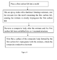
- Figure 3 is a flow chart of a method for manufacturing a composite conductive electrode according to a second embodiment the present disclosure. As shown in Figure 3 , the method comprises:
- Components of the composite conductive electrode manufactured according to the second embodiment include: a mixture of a plastic material and a conductive agent, and two overlaid pieces of a first carbon felt, wherein, the mixture evenly impregnates the two overlaid pieces of the first carbon felt, the mixture and the two overlaid pieces of the first carbon felt form an integrated structure.
- Figure 4 is a flow chart of a method for manufacturing a composite conductive electrode according to a third embodiment the present disclosure. As shown in Figure 4 , according to a third embodiment of the present disclosure, the method comprises:
- step A3 further comprises applying pressure to the first carbon felt in the mold, the pressure being applied is 1 mpa to 4 mpa; in step B3 the hardener is a commercially available commonly used hardener, the hardener may be 5% - 50% of the mixture by weight according to hardener product usage instructions.
- step D3 further comprises using a cutting machine or engraving machine to trim flat six surfaces of the composite body formed by the first carbon felt impregnated with the mixture; trimming depth is 0.1 mm to 1 mm.
- the present disclosure further provides a composite conductive electrode manufactured according to the method of the third embodiment, the composite conductive electrode comprises: a mixture of an epoxy resin and a hardener, and a first carbon felt, wherein, the mixture evenly impregnates the first carbon felt; the mixture and the first carbon felt form an integrated structure.
- Shenyang plate properties 10cm ⁇ 10cm ⁇ 1.6cm (Length x Width x Thickness), carbon content 40%.
- Pangang plate properties 10cm ⁇ 10cm ⁇ 1.6cm (Length x Width x Thickness), carbon content 20%.
- the composite conductive electrode manufactured according to the methods of the present disclosure has remarkably improved conductive properties, has a dense electrode structure, and has superior thermoplastic properties and temperature responses.
- the manufacturing process is simple and the production cost is low.
- the conductive electrode manufactured according to the methods of the present disclosure still maintains stable conductive properties and has reduced incidents of carbon fiber breakage
- the carbon felt inside the conductive plate in the conductive electrode is significantly less porous and is not easy to deform, thereby greatly prolonging the service life of the conductive electrode under stable conditions.
Abstract
Description
- The present disclosure relates to a conductive electrode for a battery and a manufacturing method thereof, particularly a composite conductive electrode and a manufacturing method thereof, and belongs to the field of vanadium battery manufacturing.
- Currently electrode materials in vanadium batteries mainly consist of non-metallic electrode plates such as plastic plates or graphite plates.
- It is discovered in practice that non-metallic electrode plates have poor conduction stability during operation, and frequently exhibit signs of breakage. Temperature of a non-metallic electrode rises when the electrode has been in operation for a long period of time. With the rising temperature, the electrode's electrical resistance tends to dramatically increase at around a threshold, causing the electrode to deform and affecting the normal operation of the non-metallic electrode. Specific problems with plastic electrode plates include poor mechanical performance and poor electrical performance. Graphite plates also have problems: graphite plates peel and deform easily, have a service life of only two years, lack longevity, and are electrically unstable.
- Composite electrode plates commonly used in vanadium batteries for redox flow are generally required to possess superior conductivity and low volume electrical resistivity, as well as superior mechanical properties and stable temperature responses. For example, after prolonged operation, especially when the temperature is elevated, the electrode plate should still maintain a stable structure during continued operation. Namely the electrode plate should have superior tolerance to deformation and resist deformation, and should retain its capability to effectively isolate solutions of different properties on two sides of the electrode plate.
- Published Chinese patent application with application number
2008103034837 - There are several shortcomings with the previously described composite electrode and its manufacturing method. First, it is very difficult in reality to achieve the required volume electrical resistivity of ≤0.1 Ω· cm. The reason is that the conductive filler content such as conductive carbon fibers in the final product is still relatively small. In addition, the mechanical structure of the heat and pressure formed composite conductive plate is unstable, and after prolonged operation of the battery the conductive carbon fibers tend to break, causing the composite electrode plate to exhibit impaired temperature responses.
- In order to overcome the technological shortcomings of the presently known non-metallic electrode plate, namely its inferior conduction stability during operation, and its tendency to break and to deform, the present disclosure discloses a method for manufacturing a composite conductive electrode.
- In order to overcome the technological shortcomings of the presently known non-metallic electrode plate, namely its inferior conduction stability during operation, and its tendency to break and to deform, the present disclosure further provides a composite conductive electrode.
- The present disclosure provides a method for manufacturing a composite conductive electrode. The method comprises: selecting a carbon felt as a conductive substrate, selecting a conductive medium as a connecting substance for spaces in the carbon felt so as to enhance conductive properties of the carbon felt.
- According to a preferred embodiment of the present disclosure, the method comprises: selecting the carbon felt as a conductive substrate, selecting a conductive resin as the connecting substance for spaces in the carbon felt so as to enhance the conductive properties of the carbon felt; the conductive resin comprises a conductive plastic material or an epoxy resin.
- According to a first embodiment of the present disclosure, the method comprises:
- A1: forming a conductive plastic sheet by mixing a plastic material and a conductive agent;
- B1: placing the conductive plastic sheet into a mold, heating the conductive plastic sheet to a temperature of 50°C to 250°C;
- C1: placing a first carbon felt on the conductive plastic sheet, heating the conductive plastic sheet and the first carbon felt to a temperature of 50°C to 250°C;
- D1: while maintaining temperature at around 50°C to 250°C, applying pressure to the conductive plastic sheet and the first carbon felt, causing the first carbon felt to fully compress the conductive plastic sheet, and causing conductive plastic to be pressed into the first carbon felt, integrated and evenly distributed into the first carbon felt, after cooling and solidifying removing a composite body formed by the conductive plastic and the first carbon felt;
- E1: trimming flat a surface of the composite body;
- F1: pressing a second carbon felt into the composite body formed by the conductive plastic and the first carbon felt by pressing one piece of the second carbon felt into a top surface of the composite body and one piece of the second carbon felt into a bottom surface of the composite body, causing the two pieces of the second carbon felt and the composite body to form an integrated structure;
- G1: cooling the integrated structure to obtain the composite conductive electrode.
- According to a preferred embodiment of the first embodiment of the present disclosure, step A1 comprises thoroughly mixing the plastic material and the conductive agent forming a mixture, wherein the conductive agent is 5% to 40% of the mixture by weight,
the plastic material comprises one or more of PE plastic pellets, PP plastic pellets or PVC plastic pellets, proportion of each plastic material can be any ratio when selecting a combination of two or more plastic materials;
the conductive agent comprises one or more of conductive carbon black, carbon nanotubes, graphite powder or acetylene black, proportion of each conductive agent can be any ratio when selecting a combination of two or more conductive agents;
the conductive plastic sheet is formed by die-casting or injection molding;
step C1 comprises placing a first carbon felt of equal size as the conductive plastic sheet on top of the conductive plastic sheet;
in step D1 the pressure applied is 1 mpa to 4 mpa using a press adapted for applying flat pressure, while maintaining constant pressure, turning over the mold containing the conductive plastic sheet and the first carbon felt, causing the first carbon felt to fully compress the conductive plastic sheet, and causing conductive plastic to be pressed into the first carbon felt, integrated and evenly distributed into the first carbon felt, after cooling and solidifying removing a composite body formed by the conductive plastic and the first carbon felt;
step E1 comprises using a cutting machine or engraving machine to trim flat a top surface and a bottom surface of the composite body, trimming depth is 0.1 mm to 1 mm;
step F1 comprises pressing two pieces of a second carbon felt each having a thickness of 2 mm to 22 mm into the composite body by pressing one piece of the second carbon felt into the top surface of the composite body and one piece of the second carbon felt into the bottom surface of the composite body, causing the two pieces of the second carbon felt and the composite body to form an integrated structure. - The present disclosure further provides a composite conductive electrode manufactured according to the method of the first embodiment, the composite conductive electrode comprises: a composite body formed by a conductive plastic and a first carbon felt, and two pieces of a second carbon felt, wherein, each piece of the second carbon felt is pressed into the composite body, forming an integrated structure with the composite body.
- According to a second embodiment of the present disclosure, the method comprises:
- A2: overlaying two pieces of a first carbon felt, placing the two overlaid pieces of the first carbon felt into a mold, heating the two overlaid pieces of the first carbon felt to a temperature of 50°C to 250°C;
- B2: applying pressure to the two overlaid pieces of the first carbon felt;
- C2: thoroughly mixing a plastic material and a conductive agent forming a mixture, heating the mixture to a temperature of 50°C to 250°C;
- D2: casting the mixture onto the two overlaid pieces of the first carbon felt, causing the mixture to evenly impregnate the two overlaid pieces of the first carbon felt;
- E2: cooling the two overlaid pieces of the first carbon felt impregnated with the mixture;
- F2: trimming flat a surface of a cooled composite body formed by the two overlaid pieces of the first carbon felt impregnated with the mixture, obtaining the composite conductive electrode.
- According to a preferred embodiment of the second embodiment of the present disclosure, in step B2 the pressure applied is 1 mpa to 4 mpa;
in step C2 the conductive agent is 5 % to 40 % of the mixture by weight,
the plastic material comprises one or more of PE plastic pellets, PP plastic pellets or PVC plastic pellets, proportion of each plastic material can be any ratio when selecting a combination of two or more plastic materials;
the conductive agent comprises one or more of conductive carbon black, carbon nanotubes, graphite powder or acetylene black, proportion of each conductive agent can be any ratio when selecting a combination of two or more conductive agents;
step F2 comprises using a cutting machine or engraving machine to trim flat six surfaces of the composite body formed by the two overlaid pieces of the first carbon felt impregnated with the mixture, trimming depth is 0.1 mm to 1 mm. - The present disclosure further provides a composite conductive electrode manufactured according to the method of the second embodiment, the composite conductive electrode comprises: a mixture of a plastic material and a conductive agent, and two overlaid pieces of a first carbon felt, wherein, the mixture evenly impregnates the two overlaid pieces of the first carbon felt, the mixture and the two overlaid pieces of the first carbon felt form an integrated structure.
- According to a third embodiment of the present disclosure, the method comprises:
- A3: placing a first carbon felt into a mold;
- B3: mixing an epoxy resin with a hardener forming a mixture, casting the mixture into the mold containing the first carbon felt, causing the mixture to evenly impregnate the first carbon felt;
- C3: removing a composite body after the mixture and the first carbon felt have solidified into an integrated structure;
- D3: trimming flat a surface of the composite body formed by the first carbon felt impregnated with the mixture, obtaining the composite conductive electrode.
- According to a preferred embodiment of the third embodiment of the present disclosure,
step A3 further comprises applying pressure to the first carbon felt in the mold, the pressure being applied is 1 mpa to 4 mpa;
in step B3 the hardener is an acidic curing agent, and the proportional weight of the hardener in the mixture is calculated according to the following formula: Amine Dosage = MG/Hn, where M=Amine molecular weight; Hn=Number of active hydrogens; G=Epoxide number (epoxide equivalents per 1000 grams of epoxy resin). When anhydrides is used the proportional weight of the hardener in the mixture is calculate according to the following formula: Anhydride Dosage = MG (0.6∼1)/100, where M=Anhydride molecular weight; G=Epoxy number (0.6 to 1) which is an experimental coefficient;
step D3 further comprises using a cutting machine or engraving machine to trim flat six surfaces of the composite body formed by the first carbon felt impregnated with the mixture; trimming depth is 0.1 mm to 1 mm. - The present disclosure further provides a composite conductive electrode manufactured according to the method of the third embodiment, the composite conductive electrode comprises: a mixture of an epoxy resin and a hardener, and a first carbon felt, wherein, the mixture evenly impregnates the first carbon felt; the mixture and the first carbon felt form an integrated structure.
- The composite conductive electrode manufactured according to the aforementioned methods has remarkably improved conductive properties, has a dense electrode structure, and has superior thermoplastic properties and temperature responses. In addition, the manufacturing process is simple and the production cost is low. Even after prolonged operation, the conductive electrode manufactured according to the methods of the present disclosure still maintains stable conductive properties and has reduced incidents of carbon fiber breakage. The carbon felt inside the conductive plate in the conductive electrode is significantly less porous and is not easy to deform, thereby greatly prolonging the service life of the conductive electrode under stable conditions.
-
-
Figure 1 is a flow chart of a method for manufacturing a composite conductive electrode according to the present disclosure; -
Figure 2 is a flow chart of a method for manufacturing a composite conductive electrode according to a first embodiment the present disclosure; -
Figure 3 is a flow chart of a method for manufacturing a composite conductive electrode according to a second embodiment the present disclosure; and -
Figure 4 is a flow chart of a method for manufacturing a composite conductive electrode according to a third embodiment the present disclosure. - The following, together with the drawings and examples, provides a detailed description of the present disclosure.
-
Figure 1 is a flow chart of a method for manufacturing a composite conductive electrode according to the present disclosure. - As shown in
Figure 1 , the method comprises: selecting a carbon felt as a conductive substrate, selecting a conductive medium as a connecting substance for spaces in the carbon felt so as to enhance conductive properties of the carbon felt. According to a preferred embodiment of the present disclosure, the method for manufacturing a composite conductive electrode comprises: selecting a carbon felt as a conductive substrate, selecting a conductive resin as a connecting substance for spaces in the carbon felt so as to enhance conductive properties of the carbon felt; the conductive resin comprises a conductive plastic material or an epoxy resin. -
Figure 2 is a flow chart of a method for manufacturing a composite conductive electrode according to a first embodiment the present disclosure. As shown inFigure 2 , the method comprises: - A1: forming a conductive plastic sheet by mixing a plastic material and a conductive agent;
- B1: placing the conductive plastic sheet into a mold, heating the conductive plastic sheet to a temperature of 50°C to 250°C;
- C1: placing the first carbon felt on the conductive plastic sheet, heating the conductive plastic sheet and the first carbon felt to a temperature of 50°C to 250°C;
- D1: while maintaining temperature at around 50°C to 250°C, applying pressure to the conductive plastic sheet and the first carbon felt, causing the first carbon felt to fully compress the conductive plastic sheet, and causing conductive plastic to be pressed into the first carbon felt, integrated and evenly distributed into the first carbon felt, after cooling and solidifying removing a composite body formed by the conductive plastic and the first carbon felt;
- E1: trimming flat a surface of the composite body;
- F1: pressing a second carbon felt into the composite body by pressing one piece of a second carbon felt into a top surface of the composite body and one piece of a second carbon felt into a bottom surface of the composite body, causing the two pieces of the second carbon felt and the composite body to form an integrated structure;
- G1: cooling the integrated structure to obtain the composite conductive electrode.
- According to a preferred embodiment of the first embodiment of the present disclosure: step A1 comprises thoroughly mixing the plastic material and the conductive agent forming a mixture, wherein the conductive agent is 5 % to 40 % of the mixture by weight,
the plastic material comprises one or more of PE plastic pellets, PP plastic pellets or PVC plastic pellets, proportion of each plastic material can be any ratio when selecting a combination of two or more plastic materials;
the conductive agent comprises one or more of conductive carbon black, carbon nanotubes, graphite powder or acetylene black, proportion of each conductive agent can be any ratio when selecting a combination of two or more conductive agents;
the conductive plastic sheet is formed by die-casting or injection molding;
step C1 comprises placing a first carbon felt of equal size as the conductive plastic sheet on top of the conductive plastic sheet;
in step D1 the pressure applied is 1 mpa to 4 mpa using a press adapted for applying flat pressure, while maintaining constant pressure, turning over the mold containing the conductive plastic sheet and the first carbon felt, causing the first carbon felt to fully compress the conductive plastic sheet, and causing conductive plastic to be pressed into the first carbon felt, integrated and evenly distributed into the first carbon felt, after cooling and solidifying removing a composite body formed by the conductive plastic and the first carbon felt;
step E1 comprises using a cutting machine or engraving machine to trim flat a top surface and a bottom surface of the composite body, trimming depth is 0.1 mm to 1 mm;
step F1 comprises pressing two pieces of a second carbon felt each having a thickness of 2 mm to 22 mm into the composite body by pressing one piece of the second carbon felt into the top surface of the composite body and one piece of the second carbon felt into the bottom surface of the composite body, causing the two pieces of the second carbon felt and the composite body to form an integrated structure. - The present disclosure further provides a composite conductive electrode manufactured according to the method of the first embodiment, the composite conductive electrode comprises: a composite body formed by a conductive plastic and a first carbon felt, and two pieces of a second carbon felt, wherein, each piece of the second carbon felt is pressed into the composite body, forming an integrated structure with the composite body.
-
- A1: Thoroughly mix a plastic material (the plastic material selected is PE plastic pellets) and a conductive agent (the conductive agent selected is conductive carbon black), the conductive agent is 5% of the mixture by weight, form the mixture into a conductive plastic sheet;
- B1: place the conductive plastic sheet into a mold, heat the conductive plastic sheet to 50°C;
- C1: place a first carbon felt of equal size as the conductive plastic sheet on top of the conductive plastic sheet, heat the conductive plastic sheet and the first carbon felt to 50°C;
- D1: while maintaining temperature at around 50°C, apply pressure to the conductive plastic sheet and the first carbon felt, the pressure applied is 4 mpa. While maintaining constant pressure, turn over the mold containing the conductive plastic sheet and the first carbon felt, causing the first carbon felt to fully compress the conductive plastic sheet, and causing conductive plastic to be pressed into the first carbon felt, integrated and evenly distributed into the first carbon felt, after cooling and solidifying remove a composite body formed by the conductive plastic and the first carbon felt;
- E1: use an engraving machine to trim flat a top surface and a bottom surface of the composite body, trimming depth is 1 mm;
- F1: press two pieces of a second carbon felt each having a thickness of 2 mm into the composite body by pressing one piece of the second carbon felt into the top surface of the composite body and one piece of the second carbon felt into the bottom surface of the composite body, causing the two pieces of the second carbon felt and the composite body to form an integrated structure;
- G1: cool the integrated structure to obtain the composite conductive electrode.

- Properties of the composite conductive electrode manufactured according to aforementioned methods:
Current (A) Voltage (V) Temperature (°C) Volume electrical Resistivity (Ω·mm2/m) 1A 0.065V 31°C 0.0021 2A 0.12V 31.3°C 0.00197 3A 0.18V 31.4°C 0.00195 4A 0.241V 31.8°C 0.00193 5A 0.298V 32°C 0.00191 8A 0.464V 32.5°C 0.00189 10A 0.573V 33.3°C 0.00188 15A 0.863V 35°C 0.0019 -
- A1: thoroughly mix a plastic material (the plastic material selected is PP plastic pellets) and a conductive agent (the conductive agent selected is conductive graphite powder), the conductive agent is 10% of the mixture by weight, form the mixture into a conductive plastic sheet;
- B1: place the conductive plastic sheet into a mold, heat the conductive plastic sheet to 100°C;
- C1: place a first carbon felt of equal size as the conductive plastic sheet on top of the conductive plastic sheet, heat the conductive plastic sheet and the first carbon felt to 100°C;
- D1: while maintaining temperature at around 100°C, apply pressure to the conductive plastic sheet and the first carbon felt, the pressure applied is 3 mpa, while maintaining constant pressure, turn over the mold containing the conductive plastic sheet and the first carbon felt, causing the first carbon felt to fully compress the conductive plastic sheet, and causing conductive plastic to be pressed into the first carbon felt, integrated and evenly distributed into the first carbon felt, after cooling and solidifying remove a composite body formed by the conductive plastic and the first carbon felt;
- E1: use an engraving machine to trim flat a top surface and a bottom surface of the composite body, trimming depth is 0.7 mm;
- F1: press two pieces of a second carbon felt each having a thickness of 10 mm into the composite body by pressing one piece of the second carbon felt into the top surface of the composite body and one piece of the second carbon felt into the bottom surface of the composite body, causing the two pieces of the second carbon felt and the composite body to form an integrated structure;
- G1: cool the integrated structure to obtain the composite conductive electrode.

- Properties of the composite conductive electrode manufactured according to aforementioned methods:
Current (A) Voltage (V) Temperature (°C) Volume electrical Resistivity (Ω·mm2/m) 1A 0.036V 31°C 0.0018 2A 0.068V 31°C 0.001745 3A 0.103V 31°C 0.001749 4A 0.14V 31.2°C 0.001728 5A 0.173V 31.3°C 0.001741 8A 0.275V 31.5°C 0.001713 10A 0.343V 31.8°C 0.00171 15A 0.534V 32°C 0.00172 -
- A1: thoroughly mix a plastic material (the plastic material selected is PVC plastic pellets) and a conductive agent (the conductive agent selected is acetylene black), the conductive agent is 10% of the mixture by weight, form the mixture into a conductive plastic sheet;
- B1: place the conductive plastic sheet into a mold, heat the conductive plastic sheet to 150°C;
- C1: place a first carbon felt of equal size as the conductive plastic sheet on top of the conductive plastic sheet, heat the conductive plastic sheet and the first carbon felt to 150°C;
- D1: while maintaining temperature at around 150°C, apply pressure to the conductive plastic sheet and the first carbon felt, the pressure applied is 2 mpa, while maintaining constant pressure, turn over the mold containing the conductive plastic sheet and the first carbon felt, causing the first carbon felt to fully compress the conductive plastic sheet, and causing conductive plastic to be pressed into the first carbon felt, integrated and evenly distributed into the first carbon felt, after cooling and solidifying remove a composite body formed by the conductive plastic and the first carbon felt;
- E1: use an engraving machine to trim flat a top surface and a bottom surface of the composite body, trimming depth is 0.5 mm;
- F1: press two pieces of a second carbon felt each having a thickness of 15 mm into the composite body by pressing one piece of the second carbon felt into the top surface of the composite body and one piece of the second carbon felt into the bottom surface of the composite body, causing the two pieces of the second carbon felt and the composite body to form an integrated structure;
- G1: cool the integrated structure to obtain the composite conductive electrode.

- Properties of the composite conductive electrode manufactured according to aforementioned methods:
Current (A) Voltage (V) Temperature (°C) Volume electrical Resistivity (Ω·mm2/m) 1A 0.040V 31°C 0.002 2A 0.078V 31°C 0.00195 3A 0.117V 31°C 0.00195 4A 0.154V 31.2°C 0.001925 5A 0.191V 31.3°C 0.00191 8A 0.298V 31.5°C 0.001863 10A 0.368V 31.8°C 0.00184 15A 0.561V 32°C 0.00187 -
- A1: thoroughly mix plastic materials (the plastic materials selected are PE plastic pellets and PP plastic pellets, at a 1:1 ratio) and a conductive agent (the conductive agent selected is carbon nanotubes), the conductive agent is 10% of the mixture by weight, form the mixture into a conductive plastic sheet;
- B1: place the conductive plastic sheet into a mold, heat the conductive plastic sheet to 200°C;
- C1: place a first carbon felt of equal size as the conductive plastic sheet on top of the conductive plastic sheet, heat the conductive plastic sheet and the first carbon felt to 200°C;
- D1: while maintaining temperature at around 200°C, apply pressure to the conductive plastic sheet and the first carbon felt, the pressure applied is 2 mpa, while maintaining constant pressure, turn over the mold containing the conductive plastic sheet and the first carbon felt, causing the first carbon felt to fully compress the conductive plastic sheet, and causing conductive plastic to be pressed into the first carbon felt, integrated and evenly distributed into the first carbon felt, after cooling and solidifying remove a composite body formed by the conductive plastic and the first carbon felt;
- E1: use an engraving machine to trim flat a top surface and a bottom surface of the composite body, trimming depth is 0.3 mm;
- F1: press two pieces of a second carbon felt each having a thickness of 20 mm into the composite body by pressing one piece of the second carbon felt into the top surface of the composite body and one piece of the second carbon felt into the bottom surface of the composite body, causing the two pieces of the second carbon felt and the composite body to form an integrated structure;
- G1: cool the integrated structure to obtain the composite conductive electrode.

- Properties of the composite conductive electrode manufactured according to aforementioned methods:
Current (A) Voltage (V) Temperature (°C) Volume electrical Resistivity (Ω·mm2/m) 1A 0.020V 31°C 0.001 2A 0.035V 31°C 0.00093 3A 0.055V 31°C 0.00093 4A 0.072V 31.2°C 0.00094 5A 0.091V 31.3°C 0.00093 8A 0.138V 31.5°C 0.000871 10A 0.172V 31.8°C 0.000868 15A 0.263V 32°C 0.000878 -
- A1: thoroughly mix plastic materials (the plastic materials selected are PE plastic pellets, PP plastic pellets and PVC plastic pellets, at a 1: 1: 1 ratio) and conductive agents (the conductive agents selected are conductive carbon black, graphite powder and acetylene black, at a 1: 1: 1 ratio), the conductive agents are 20% of the mixture by weight, form the mixture into a conductive plastic sheet;
- B1: place the conductive plastic sheet into a mold, heat the conductive plastic sheet to 250°C;
- C1: place a first carbon felt of equal size as the conductive plastic sheet on top of the conductive plastic sheet, heat the conductive plastic sheet and the first carbon felt to 250°C;
- D1: while maintaining temperature at around 250°C, apply pressure to the conductive plastic sheet and the first carbon felt, the pressure applied is 1 mpa, while maintaining constant pressure, turn over the mold containing the conductive plastic sheet and the first carbon felt, causing the first carbon felt to fully compress the conductive plastic sheet, and causing conductive plastic to be pressed into the first carbon felt, integrated and evenly distributed into the first carbon felt, after cooling and solidifying remove a composite body formed by the conductive plastic and the first carbon felt;
- E1: use an engraving machine to trim flat a top surface and a bottom surface of the composite body, trimming depth is 0.1 mm;
- F1: press two pieces of a second carbon felt each having a thickness of 22 mm into the composite body by pressing one piece of the second carbon felt into the top surface of the composite body and one piece of the second carbon felt into the bottom surface of the composite body, causing the two pieces of the second carbon felt and the composite body to form an integrated structure;
- G1: cool the integrated structure to obtain the composite conductive electrode.

- Properties of the composite conductive electrode manufactured according to aforementioned methods:
Current (A) Voltage (V) Temperature (°C) Volume electrical Resistivity (Ω·mm2/m) 1A 0.026V 31°C 0.00085 2A 0.045V 31°C 0.000719 3A 0.063V 31°C 0.00068 4A 0.081V 31.2°C 0.00066 5A 0.01V 31.3°C 0.000655 8A 0.154V 31.5°C 0.000649 10A 0.19V 31.8°C 0.000566 15A 0.282V 32°C 0.000625 -
Figure 3 is a flow chart of a method for manufacturing a composite conductive electrode according to a second embodiment the present disclosure. As shown inFigure 3 , the method comprises: - A2: overlaying two pieces of a first carbon felt, placing the two overlaid pieces of the first carbon felt into a mold, heating the two overlaid pieces of the first carbon felt to a temperature of 50°C to 250°C;
- B2: applying pressure to the two overlaid pieces of the first carbon felt;
- C2: thoroughly mixing a plastic material and a conductive agent forming a mixture, heating the mixture to a temperature of 50°C to 250°C;
- D2: casting the mixture onto the two overlaid pieces of the first carbon felt, causing the mixture to evenly impregnate the two overlaid pieces of the first carbon felt;
- E2: cool the two overlaid pieces of the first carbon felt impregnated with the mixture;
- F2: trimming flat a surface of a cooled composite body formed by the two overlaid pieces of the first carbon felt impregnated with the mixture, obtaining the composite conductive electrode.
- According to a preferred embodiment of the second embodiment of the present disclosure:
- in step B2 the pressure applied is 1 mpa to 4 mpa;
- in step C2 the conductive agent is 5 % to 40 % of the mixture by weight, the plastic material comprises one or more of PE plastic pellets, PP plastic pellets or PVC plastic pellets, proportion of each plastic material can be any ratio when selecting a combination of two or more plastic materials; the conductive agent comprises one or more of conductive carbon black, carbon nanotubes, graphite powder or acetylene black, proportion of each conductive agent can be any ratio when selecting a combination of two or more conductive agents;
- step F2 comprises using a cutting machine or engraving machine to trim flat six surfaces of the composite body formed by the two overlaid pieces of the first carbon felt impregnated with the mixture, trimming depth is 0.1 mm to 1 mm.
- Components of the composite conductive electrode manufactured according to the second embodiment include: a mixture of a plastic material and a conductive agent, and two overlaid pieces of a first carbon felt, wherein, the mixture evenly impregnates the two overlaid pieces of the first carbon felt, the mixture and the two overlaid pieces of the first carbon felt form an integrated structure.
-
- A2: overlay two pieces of a first carbon felt, place the two overlaid pieces of the first carbon felt into a mold, heat the conductive plastic sheet to 50°C;
- B2: apply pressure to the two overlaid pieces of the first carbon felt, the pressure applied is 4 mpa;
- C2: thoroughly mix a plastic material (the plastic material selected is PE plastic pellets) and conductive agents (the conductive agents selected are conductive carbon black and carbon nanotubes, at a 4:1 ratio), wherein the conductive agents are 5 % of the mixture by weight, and heat the mixture to 250°C;
- D2: cast the mixture onto the two overlaid pieces of the first carbon felt, causing the mixture to evenly impregnate the two overlaid pieces of the first carbon felt;
- E2: cool the two overlaid pieces of the first carbon felt impregnated with the mixture;
- F2: trim flat a surface of a cooled composite body formed by the two overlaid pieces of the first carbon felt impregnated with the mixture, trimming depth is 0.1 mm, obtain the composite conductive electrode.

- Properties of the composite conductive electrode manufactured according to aforementioned methods:
Current (A) Voltage (V) Temperature (°C) Volume electrical Resistivity (Ω·mm2/m) 1A 0.008V 31°C 0.000298 2A 0.016V 31°C 0.000282 3A 0.025V 31°C 0.000277 4A 0.031V 31°C 0.000265 5A 0.04V 31°C 0.000262 8A 0.06V 31°C 0.00025 10A 0.075V 31°C 0.0002445 15A 0.11V 31.3°C 0.000245 -
- A2: overlay two pieces of a first carbon felt, place the two overlaid pieces of the first carbon felt into a mold, heat the two overlaid pieces of the first carbon felt to 100°C;
- B2: apply pressure to the two overlaid pieces of the first carbon felt, the pressure applied is 3 mpa,
- C2: thoroughly mix a plastic material (the plastic material selected is PVC plastic pellets) and conductive agents (the conductive agents selected are acetylene black and carbon nanotubes, at a 4:1 ratio), the conductive agent is 10% of the mixture by weight, heat the mixture to 200°C;
- D2: cast the mixture onto the two overlaid pieces of the first carbon felt, causing the mixture to evenly impregnate the two overlaid pieces of the first carbon felt;
- E2: cool the two overlaid pieces of the first carbon felt impregnated with the mixture;
- F2: trim flat a surface of a cooled composite body formed by the two overlaid pieces of the first carbon felt impregnated with the mixture, trimming depth is 0.3 mm; obtain the composite conductive electrode.

- Properties of the composite conductive electrode manufactured according to aforementioned methods:
Current (A) Voltage (V) Temperature (°C) Volume electrical Resistivity (Ω·mm2/m) 1A 0.005V 31°C 0.00015 2A 0.01V 31°C 0.00018 3A 0.017V 31°C 0.00019 4A 0.022V 31°C 0.000195 5A 0.026V 31°C 0.000185 8A 0.045V 31°C 0.000185 10A 0.06V 31°C 0.0002 15A 0.083V 31°C 0.000198 -
- A2: overlay two pieces of a first carbon felt, place the two overlaid pieces of the first carbon felt into a mold, heat the two overlaid pieces of the first carbon felt to 150°C;
- B2: apply pressure to the two overlaid pieces of the first carbon felt, the pressure applied is 2 mpa,
- C2: thoroughly mix a plastic material (the plastic material selected is PP plastic pellets) and a conductive agent (the conductive agent selected is conductive graphite powder), the conductive agent is 15% of the mixture by weight, heat the mixture to 150°C;
- D2: cast the mixture onto the two overlaid pieces of the first carbon felt, causing the mixture to evenly impregnate the two overlaid pieces of the first carbon felt;
- E2: cool the two overlaid pieces of the first carbon felt impregnated with the mixture;
- F2: trim flat a surface of a cooled composite body formed by the two overlaid pieces of the first carbon felt impregnated with the mixture, trimming depth is 0.5 mm; obtain the composite conductive electrode.

- Properties of the composite conductive electrode manufactured according to aforementioned methods:
Current (A) Voltage (V) Temperature (°C) Volume electrical Resistivity (Ω·mm2/m) 1A 0.005V 31°C 0.000145 2A 0.006V 31°C 0.0000873 3A 0.009V 31°C 0.0000855 4A 0.012V 31°C 0.0000857 5A 0.015V 31°C 0.0000855 8A 0.024V 31°C 0.0000855 10A 0.029V 31°C 0.000083 15A 0.044V 31°C 0.0000831 -
- A2: overlay two pieces of a first carbon felt, place the two overlaid pieces of the first carbon felt into a mold, heat the two overlaid pieces of the first carbon felt to 200°C;
- B2: apply pressure to the two overlaid pieces of the first carbon felt, the pressure applied is 2 mpa,
- C2: thoroughly mix plastic materials (the plastic materials selected are PE plastic pellets, PP plastic pellets and PVC plastic pellets, at a 1: 1: 1 ratio) and conductive agents (the conductive agents selected are graphite powder and carbon nanotubes at a 2:1 ratio), the conductive agents are 20% of the mixture by weight, heat the mixture to 100°C;
- D2: cast the mixture onto the two overlaid pieces of the first carbon felt, causing the mixture to evenly impregnate the two overlaid pieces of the first carbon felt;
- E2: cool the two overlaid pieces of the first carbon felt impregnated with the mixture;
- F2: trim flat a surface of a cooled composite body formed by the two overlaid pieces of the first carbon felt impregnated with the mixture, trimming depth is 0.5 mm; obtain the composite conductive electrode.

- Properties of the composite conductive electrode manufactured according to aforementioned methods:
Current (A) Voltage (V) Temperature (°C) Volume electrical Resistivity (Ω·mm2/m) 1A 0.003V 31°C 0.00012 2A 0.005V 31°C 0.000102 3A 0.007V 31°C 0.000097 4A 0.010V 31°C 0.000102 5A 0.013V 31°C 0.000102 8A 0.020V 31°C 0.000102 10A 0.024V 31°C 0.000102 15A 0.036V 31°C 0.000101 -
- A2: overlay two pieces of a first carbon felt, place the two overlaid pieces of the first carbon felt into a mold, heat the two overlaid pieces of the first carbon felt to 250°C;
- B2: apply pressure to the two overlaid pieces of the first carbon felt, the pressure applied is 1 mpa,
- C2: thoroughly mix plastic materials (the plastic materials selected are PE plastic pellets, PP plastic pellets and PVC plastic pellets, at a 1: 1: 1 ratio) and conductive agents (the conductive agents selected are conductive carbon black, graphite powder and carbon nanotubes at a 1: 1: 1 ratio), the conductive agents are 20% of the mixture by weight, heat the mixture to 50°C;
- D2: cast the mixture onto the two overlaid pieces of the first carbon felt, causing the mixture to evenly impregnate the two overlaid pieces of the first carbon felt;
- E2: cool the two overlaid pieces of the first carbon felt impregnated with the mixture;
- F2: trim flat a surface of a cooled composite body formed by the two overlaid pieces of the first carbon felt impregnated with the mixture, trimming depth is 1 mm; obtain the composite conductive electrode.

- Properties of the composite conductive electrode manufactured according to aforementioned methods:
Current (A) Voltage (V) Temperature (°C) Volume electrical Resistivity (Ω·mm2/m) 1A 0.003V 30°C 0.000123 2A 0.005V 30°C 0.000102 3A 0.006V 30°C 0.000083 4A 0.009V 30°C 0.0009372 5A 0.012V 30°C 0.0009372 8A 0.015V 30°C 0.0009372 10A 0.020V 30°C 0.0009372 15A 0.033V 30°C 0.0009173 -
Figure 4 is a flow chart of a method for manufacturing a composite conductive electrode according to a third embodiment the present disclosure. As shown inFigure 4 , According to a third embodiment of the present disclosure, the method comprises: - A3: placing a first carbon felt into a mold;
- B3: mixing an epoxy resin with a hardener forming a mixture, casting the mixture into the mold containing the first carbon felt, causing the mixture to evenly impregnate the first carbon felt;
- C3: removing a composite body after the mixture and the first carbon felt have solidified into an integrated structure;
- D3: trimming flat a surface of the composite body formed by the first carbon felt impregnated with the mixture, obtaining the composite conductive electrode.
- According to a preferred embodiment of the third embodiment of the present disclosure,
step A3 further comprises applying pressure to the first carbon felt in the mold, the pressure being applied is 1 mpa to 4 mpa;
in step B3 the hardener is a commercially available commonly used hardener, the hardener may be 5% - 50% of the mixture by weight according to hardener product usage instructions.
step D3 further comprises using a cutting machine or engraving machine to trim flat six surfaces of the composite body formed by the first carbon felt impregnated with the mixture; trimming depth is 0.1 mm to 1 mm. - The present disclosure further provides a composite conductive electrode manufactured according to the method of the third embodiment, the composite conductive electrode comprises: a mixture of an epoxy resin and a hardener, and a first carbon felt, wherein, the mixture evenly impregnates the first carbon felt; the mixture and the first carbon felt form an integrated structure.
-
- A3: place a first carbon felt into a mold, apply pressure of 1 mpa to the first carbon felt;
- B3: mix an epoxy resin with a hardener forming a mixture, cast the mixture into the mold containing the first carbon felt, causing the mixture to evenly impregnate the first carbon felt, the hardener is a commercially available commonly used hardener, the hardener may be 5% - 50% of the mixture by weight according to hardener product usage instructions. In this example the hardener is 5% of the mixture by weight.
- C3: remove a composite body after the mixture and the first carbon felt have solidified into an integrated structure;
- D3: trim flat a surface of the composite body formed by the first carbon felt impregnated with the mixture, trimming depth is 0.1 mm, obtain the composite conductive electrode.

- Properties of the composite conductive electrode manufactured according to aforementioned methods:
Current (A) Voltage (V) Temperature (°C) Volume electrical Resistivity (Ω·mm2/m) 1A 0.008V 31.1°C 0.000755 2A 0.018V 31.1°C 0.00076 3A 0.027V 31.1°C 0.00075 4A 0.035V 31.1°C 0.000745 5A 0.043V 31.1°C 0.000756 8A 0.073V 31.2°C 0.000758 10A 0.092V 31.2°C 0.000755 15A 0.134V 31.3°C 0.000755 -
- A3: place a first carbon felt into a mold, apply pressure of 2 mpa to the first carbon felt;
- B3: mix an epoxy resin with a hardener forming a mixture, cast the mixture into the mold containing the first carbon felt, causing the mixture to evenly impregnate the first carbon felt, the hardener is a commercially available commonly used hardener, the hardener may be 5% - 50% of the mixture by weight according to hardener product usage instructions. In this example the hardener is 10% of the mixture by weight
- C3: remove a composite body after the mixture and the first carbon felt have solidified into an integrated structure;
- D3: trim flat a surface of the composite body formed by the first carbon felt impregnated with the mixture, trimming depth is 0.3 mm, obtain the composite conductive electrode.

- Properties of the composite conductive electrode manufactured according to aforementioned methods:
Current (A) Voltage (V) Temperature (°C) Volume electrical Resistivity (Ω·mm2/m) 1A 0.007V 31.1°C 0.000558 2A 0.016V 31.1°C 0.000555 3A 0.022V 31.1°C 0.00056 4A 0.03V 31.1°C 0.000556 5A 0.038V 31.1°C 0.000558 8A 0.064V 31.2°C 0.000562 10A 0.08V 31.2°C 0.000559 15A 0.114V 31.2°C 0.000558 -
- A3: place a first carbon felt into a mold, apply pressure of 3 mpa to the first carbon felt;
- B3: mix an epoxy resin with a hardener forming a mixture, cast the mixture into the mold containing the first carbon felt, causing the mixture to evenly impregnate the first carbon felt, the hardener is a commercially available commonly used hardener, the hardener may be 5% - 50% of the mixture by weight according to hardener product usage instructions. In this example the hardener is 20% of the mixture by weight.
- C3: remove a composite body after the mixture and the first carbon felt have solidified into an integrated structure;
- D3: trim flat a surface of the composite body formed by the first carbon felt impregnated with the mixture, trimming depth is 0.5 mm, obtain the composite conductive electrode.

- Properties of the composite conductive electrode manufactured according to aforementioned methods:
Current (A) Voltage (V) Temperature (°C) Volume electrical Resistivity (Ω·mm2/m) 1A 0.005V 31.2°C 0.0004 2A 0.012V 31.2°C 0.000398 3A 0.018V 31.2°C 0.000399 4A 0.023V 31.2°C 0.00041 5A 0.03V 31.2°C 0.000411 8A 0.05V 31.2°C 0.000401 10A 0.063V 31.2°C 0.000403 15A 0.092V 31.2°C 0.000405 -
- A3: place a first carbon felt into a mold, apply pressure of 4 mpa to the first carbon felt;
- B3: mix an epoxy resin with a hardener forming a mixture, cast the mixture into the mold containing the first carbon felt, causing the mixture to evenly impregnate the first carbon felt, the hardener is a commercially available commonly used hardener, the hardner may be 5% - 50% of the mixture by weight according to hardener product usage instructions. In this example the hardener is 30% of the mixture by weight.
- C3: remove a composite body after the mixture and the first carbon felt have solidified into an integrated structure;
- D3: trim flat a surface of the composite body formed by the first carbon felt impregnated with the mixture, trimming depth is 0.8 mm, obtain the composite conductive electrode.

- Properties of the composite conductive electrode manufactured according to aforementioned methods:
Current (A) Voltage (V) Temperature (°C) Volume electrical Resistivity (Ω·mm2/m) 1A 0.004V 31.2°C 0.000355 2A 0.011V 31.2°C 0.000353 3A 0.018V 31.2°C 0.000357 4A 0.022V 31.2°C 0.000358 5A 0.029V 31.2°C 0.000351 8A 0.045V 31.2°C 0.000352 10A 0.059V 31.2°C 0.000355 15A 0.089V 31.2°C 0.000356 -
- A3: place a first carbon felt into a mold, apply pressure of 4 mpa to the first carbon felt;
- B3: mix an epoxy resin with a hardener forming a mixture, cast the mixture into the mold containing the first carbon felt, causing the mixture to evenly impregnate the first carbon felt, the hardener is a commercially available commonly used hardener, the hardner may be 5% - 50% of the mixture by weight according to hardener product usage instructions. In this example the hardener is 50% of the mixture by weight.
- C3: remove a composite body after the mixture and the first carbon felt have solidified into an integrated structure;
- D3: trim flat a surface of the composite body formed by first carbon felt impregnated with the mixture, trimming depth is 1 mm; obtain the composite conductive electrode.

- Properties of the composite conductive electrode manufactured according to aforementioned methods:
Current (A) Voltage (V) Temperature (°C) Volume electrical Resistivity (Ω·mm2/m) 1A 0.004V 31.2°C 0.00035 2A 0.012V 31.2°C 0.000349 3A 0.018V 31.2°C 0.000348 4A 0.022V 31.2°C 0.000349 5A 0.028V 31.2°C 0.000352 8A 0.047V 31.2°C 0.000351 10A 0.058V 31.2°C 0.00035 15A 0.087V 31.2°C 0.00035
1. Shenyang plate properties: 10cm×10cm×1.6cm (Length x Width x Thickness), carbon content 40%.Current (A) Voltage (V) Temperature (°C) Volume electrical Resistivity (Ω·mm2/m) 1A 0.038V 31°C 0.002375 2A 0.066V 31°C 0.002063 3A 0.094V 31°C 0.00196 4A 0.122V 31°C 0.001906 5A 0.15V 31.2°C 0.001875 8A 0.234V 32.4°C 0.001828 10A 0.291V 33.8°C 0.001818 15A 0.432V 36.4°C 0.0018
2. Pangang plate properties: 10cm×10cm×1.6cm (Length x Width x Thickness), carbon content 20%.Current (A) Voltage (V) Temperature (°C) Volume electrical Resistivity (Ω·mm2/m) 1A 0.035V 31°C 0.002188 2A 0.061V 31°C 0.001906 3A 0.086V 31°C 0.00179 4A 0.112V 31°C 0.00175 5A 0.138V 31.2°C 0.001725 8A 0.211V 32.1°C 0.001648 10A 0.258V 33°C 0.001613 15A 0.381V 36.6°C 0.001588 Current (A) Voltage (V) Temperature (°C) Volume electrical Resistivity (Ω·mm2/m) 1A 0.026V 31°C 0.0005652 2A 0.045V 31°C 0.0004891 3A 0.065V 31°C 0.000471 4A 0.084V 31°C 0.000456 5A 0.103V 31°C 0.000448 8A 0.162V 31.2°C 0.000440 10A 0.200V 32°C 0.000438 15A 0.300V 33°C 0.000435 - Compared to the aforementioned products, the composite conductive electrode manufactured according to the methods of the present disclosure has remarkably improved conductive properties, has a dense electrode structure, and has superior thermoplastic properties and temperature responses. In addition, the manufacturing process is simple and the production cost is low. Even after prolonged operation, the conductive electrode manufactured according to the methods of the present disclosure still maintains stable conductive properties and has reduced incidents of carbon fiber breakage The carbon felt inside the conductive plate in the conductive electrode is significantly less porous and is not easy to deform, thereby greatly prolonging the service life of the conductive electrode under stable conditions.
- The above is intended only as a detailed description of the present disclosure in view of a particular preferred embodiment and does not limit other embodiments of the present disclosure. Any simple deduction or substitution that is within the framework of the present disclosure made by a person of ordinary skill in the art remains within the scope of protection of the present disclosure.
Claims (10)
- A method for manufacturing a composite conductive electrode, comprising:selecting a carbon felt as a conductive substrate; andselecting a conductive medium as a connecting substance for spaces in the carbon felt so as to enhance conductive properties of the carbon felt.
- The method of claim 1, further comprising:selecting the carbon felt as a conductive substrate;selecting a conductive resin as the connecting substance for spaces in the carbon felt so as to enhance the conductive properties of the carbon felt,wherein the conductive resin comprises a conductive plastic material or an epoxy resin.
- The method of claim 2, further comprising:A1: forming a conductive plastic sheet by mixing a plastic material and a conductive agent;B1: placing the conductive plastic sheet into a mold, heating the conductive plastic sheet to a temperature of 50°C to 250°C;C1: placing a first carbon felt on the conductive plastic sheet, heating the conductive plastic sheet and the first carbon felt to a temperature of 50°C to 250°C;D1: while maintaining temperature at around 50°C to 250°C, applying pressure to the conductive plastic sheet and the first carbon felt, causing the first carbon felt to fully compress the conductive plastic sheet, and causing conductive plastic to be pressed into the first carbon felt, integrated and evenly distributed into the first carbon felt, after cooling and solidifying removing a composite body formed by the conductive plastic and the first carbon felt;E1: trimming flat a surface of the composite body;F1: pressing a second carbon felt into the composite body by pressing one piece of the second carbon felt into a top surface of the composite body and one piece of the second carbon felt into a bottom surface of the composite body, causing the two pieces of the second carbon felt and the composite body to form an integrated structure; andG1: cooling the integrated structure to obtain the composite conductive electrode.
- The method of claim 3, whereinstep A1 comprises thoroughly mixing the plastic material and the conductive agent forming a mixture, wherein the conductive agent is 5 % to 40 % of the mixture by weight,
wherein the plastic material comprises one or more of PE plastic pellets, PP plastic pellets or PVC plastic pellets, proportion of each plastic material can be any ratio when selecting a combination of two or more plastic materials,
wherein the conductive agent comprises one or more of conductive carbon black, carbon nanotubes, graphite powder or acetylene black, proportion of each conductive agent can be any ratio when selecting a combination of two or more conductive agents,
wherein the conductive plastic sheet is formed by die-casting or injection molding,
wherein step C1 comprises placing the first carbon felt of equal size as the conductive plastic sheet on top of the conductive plastic sheet,
wherein in step D1 the pressure applied is 1mpa to 4 mpa using a press adapted for applying flat pressure, while maintaining constant pressure, turning over the mold containing the conductive plastic sheet and the first carbon felt, causing the first carbon felt to fully compress the conductive plastic sheet, and causing conductive plastic to be pressed into the first carbon felt, integrated and evenly distributed into the first carbon felt, after cooling and solidifying removing a composite body formed by the conductive plastic and the first carbon felt,
wherein step E1 comprises using a cutting machine or engraving machine to trim flat a top surface and a bottom surface of the composite body, trimming depth is 0.1 mm to 1 mm, and
wherein step F1 comprises pressing two pieces of the second carbon felt each having a thickness of 2 mm to 22 mm into the composite body by pressing one piece of the second carbon felt into the top surface of the composite body and one piece of the second carbon felt into the bottom surface of the composite body, causing the two pieces of the second carbon felt and the composite body to form an integrated structure. - A composite conductive electrode made by the method of claim 3, comprising:a composite body formed by a conductive plastic and a first carbon felt; andtwo pieces of a second carbon felt,wherein, each piece of the second carbon felt is pressed into the composite body, forming an integrated structure with the composite body.
- The method of claim 2, further comprising:A2: overlaying two pieces of a first carbon felt, placing the two overlaid pieces of the first carbon felt into a mold, heating the two overlaid pieces of the first carbon felt to a temperature of 50°C to 250°C;B2: applying pressure to the two overlaid pieces of the first carbon felt;C2: thoroughly mixing the plastic material and the conductive agent forming a mixture, heating the mixture to a temperature of 50°C to 250°C;D2: casting the mixture onto the two overlaid pieces of the first carbon felt, causing the mixture to evenly impregnate the two overlaid pieces of the first carbon felt;E2: cooling the two overlaid pieces of the first carbon felt impregnated with the mixture; andF2: trimming flat a surface of a cooled composite body formed by the two overlaid pieces of the first carbon felt impregnated with the mixture, obtaining the composite conductive electrode.
- The method of claim 6, wherein in step B2 the pressure applied is 1mpa to 4 mpa,
wherein in step C2 the conductive agent is 5% to 40% of the mixture by weight,
wherein the plastic material comprises one or more of PE plastic pellets, PP plastic pellets or PVC plastic pellets, proportion of each plastic material can be any ratio when selecting a combination of two or more plastic materials,
wherein the conductive agent comprises one or more of conductive carbon black, carbon nanotubes, graphite powder, or acetylene black, proportion of each conductive agent can be any ratio when selecting a combination of two or more conductive agents. and
wherein step F2 comprises using a cutting machine or engraving machine to trim flat six surfaces of the composite body formed by the two overlaid pieces of the first carbon felt impregnated with the mixture, trimming depth is 0.1 mm to 1 mm. - A composite conductive electrode made by the method of claim 6, comprising:a mixture of a plastic material and a conductive agent; andtwo overlaid pieces of a first carbon felt,wherein, the mixture evenly impregnates the two overlaid pieces of the first carbon felt, the mixture and the two overlaid pieces of the first carbon felt form an integrated structure.
- The method of claim 2, wherein the method comprises:A3: placing the first carbon felt into a mold;B3: mixing the epoxy resin with a hardener forming a mixture, casting the mixture into the mold containing the first carbon felt, causing the mixture to evenly impregnate the first carbon felt;C3: removing a composite body after the mixture and the first carbon felt have solidified into an integrated structure; andD3: trimming flat a surface of the composite body formed by the first carbon felt impregnated with the mixture, obtaining the composite conductive electrode.
- A composite conductive electrode made by the method of claim 9, comprising:a mixture of an epoxy resin and a hardener; anda first carbon felt, wherein, the mixture evenly impregnates the first carbon felt,wherein the mixture and the first carbon felt form an integrated structure.
Applications Claiming Priority (2)
| Application Number | Priority Date | Filing Date | Title |
|---|---|---|---|
| CN2011101368604A CN102324492B (en) | 2011-05-25 | 2011-05-25 | Composite conductive electrode and manufacturing method thereof |
| PCT/CN2012/076036 WO2012159582A1 (en) | 2011-05-25 | 2012-05-25 | Composite conductive electrode and manufacturing method thereof |
Publications (2)
| Publication Number | Publication Date |
|---|---|
| EP2717352A1 true EP2717352A1 (en) | 2014-04-09 |
| EP2717352A4 EP2717352A4 (en) | 2014-12-17 |
Family
ID=45452192
Family Applications (1)
| Application Number | Title | Priority Date | Filing Date |
|---|---|---|---|
| EP12788715.6A Withdrawn EP2717352A4 (en) | 2011-05-25 | 2012-05-25 | Composite conductive electrode and manufacturing method thereof |
Country Status (4)
| Country | Link |
|---|---|
| US (1) | US20140315082A1 (en) |
| EP (1) | EP2717352A4 (en) |
| CN (2) | CN102324492B (en) |
| WO (1) | WO2012159582A1 (en) |
Cited By (2)
| Publication number | Priority date | Publication date | Assignee | Title |
|---|---|---|---|---|
| EP3045497A4 (en) * | 2013-09-10 | 2017-07-26 | Riken Technos Corporation | Electrically conductive resin composition, and film produced from same |
| US10767035B2 (en) | 2014-10-09 | 2020-09-08 | Riken Technos Corporation | Method for producing thermoplastic resin composition film |
Families Citing this family (6)
| Publication number | Priority date | Publication date | Assignee | Title |
|---|---|---|---|---|
| CN102324492B (en) * | 2011-05-25 | 2013-11-27 | 深圳市金钒能源科技有限公司 | Composite conductive electrode and manufacturing method thereof |
| CN103116046B (en) * | 2012-12-12 | 2015-03-25 | 上海电气钠硫储能技术有限公司 | Preparation method for absorbing mixed fused salt carbon felt electrodes |
| CN103490075B (en) * | 2013-10-15 | 2016-03-23 | 攀钢集团攀枝花钢铁研究院有限公司 | Vanadium redox battery and end, bipolar electrode and preparation method |
| CN104409738A (en) * | 2014-11-05 | 2015-03-11 | 中国科学院金属研究所 | Making method of conductive carbon black/nanometer carbon fiber composite electrode for all-vanadium redox flow battery |
| CN108808014A (en) * | 2017-05-02 | 2018-11-13 | 苏州天裕塑胶有限公司 | A kind of preparation method of Plastic conductive plastic cement |
| US10946612B2 (en) | 2018-08-27 | 2021-03-16 | Tactotek Oy | Integrated multilayer structure for use in sensing applications and method for manufacturing thereof |
Family Cites Families (7)
| Publication number | Priority date | Publication date | Assignee | Title |
|---|---|---|---|---|
| US7232601B2 (en) * | 2001-05-31 | 2007-06-19 | Advanced Energy Technology Inc. | Method for preparing composite flexible graphite material |
| EP1502992B1 (en) * | 2002-04-17 | 2009-03-11 | Mitsubishi Rayon Co., Ltd. | Carbon fiber paper and porous carbon electrode substrate for fuel cell therefrom |
| JP2005294024A (en) * | 2004-03-31 | 2005-10-20 | Ntt Data Ex Techno Corp | Coated collector for storage battery, its manufacturing method, and storage battery having coated collector |
| CN101335349B (en) * | 2008-08-06 | 2010-06-30 | 攀枝花新钢钒股份有限公司 | Combination electrode for all vanadium redox flow battery and preparation thereof |
| CN101853942B (en) * | 2009-04-03 | 2013-02-06 | 夏嘉琪 | Double electrode plate for all-vanadium liquid flow energy storage battery and preparation method thereof |
| CN101877408B (en) * | 2009-04-30 | 2013-03-20 | 比亚迪股份有限公司 | Current collector of liquid flow battery and liquid flow battery |
| CN102324492B (en) * | 2011-05-25 | 2013-11-27 | 深圳市金钒能源科技有限公司 | Composite conductive electrode and manufacturing method thereof |
-
2011
- 2011-05-25 CN CN2011101368604A patent/CN102324492B/en active Active
- 2011-05-25 CN CN201310314858.0A patent/CN103367761B/en active Active
-
2012
- 2012-05-25 US US14/119,796 patent/US20140315082A1/en not_active Abandoned
- 2012-05-25 EP EP12788715.6A patent/EP2717352A4/en not_active Withdrawn
- 2012-05-25 WO PCT/CN2012/076036 patent/WO2012159582A1/en active Application Filing
Non-Patent Citations (2)
| Title |
|---|
| No further relevant documents disclosed * |
| See also references of WO2012159582A1 * |
Cited By (4)
| Publication number | Priority date | Publication date | Assignee | Title |
|---|---|---|---|---|
| EP3045497A4 (en) * | 2013-09-10 | 2017-07-26 | Riken Technos Corporation | Electrically conductive resin composition, and film produced from same |
| US9748017B2 (en) | 2013-09-10 | 2017-08-29 | Riken Technos Corporation | Electrically conductive resin composition, and film produced from same |
| EP3284782A1 (en) * | 2013-09-10 | 2018-02-21 | Riken Technos Corporation | Electrically conductive resin composition, and film produced from same |
| US10767035B2 (en) | 2014-10-09 | 2020-09-08 | Riken Technos Corporation | Method for producing thermoplastic resin composition film |
Also Published As
| Publication number | Publication date |
|---|---|
| CN103367761B (en) | 2015-07-08 |
| CN103367761A (en) | 2013-10-23 |
| WO2012159582A1 (en) | 2012-11-29 |
| EP2717352A4 (en) | 2014-12-17 |
| CN102324492B (en) | 2013-11-27 |
| US20140315082A1 (en) | 2014-10-23 |
| CN102324492A (en) | 2012-01-18 |
Similar Documents
| Publication | Publication Date | Title |
|---|---|---|
| EP2717352A1 (en) | Composite conductive electrode and manufacturing method thereof | |
| CN102208659A (en) | Manufacturing process and device of bipolar plate for fuel cell | |
| CN104704664B (en) | For with electrochemical cell associated with fluidal texture | |
| WO2003071625A3 (en) | Method of fabricating fluid flow field plates | |
| CN102473930B (en) | Method for producing a fuel cell separator | |
| CN103117397A (en) | Manufacturing technique of bipolar plate for fuel battery | |
| CN113224339B (en) | Flexible ultrathin graphite bipolar plate and preparation method thereof | |
| EP1280217A2 (en) | Fuel-cell separator, production of the same, and fuel cell | |
| CN109910259A (en) | Fuel battery pole board forming method based on expanded graphite | |
| CN108321400A (en) | Fuel cell is molded the pairs of production method of bipolar plates | |
| JP6058786B2 (en) | Carbon plate and composite carbon plate | |
| CN102643515A (en) | Low-resistivity composite conductive plate and preparation method thereof | |
| CN102544518A (en) | Dual-material co-injection molding bipolar plate and manufacturing method thereof | |
| CN109950556B (en) | Preparation method of carbon fiber bipolar plate with three-dimensional porous structure | |
| CN102082276B (en) | Manufacturing method of composite plastic conductive electrode and conductive electrode manufactured by same | |
| CN114520357A (en) | Three-in-one electrode material for flow battery and its production process and apparatus | |
| CN104201005A (en) | Manufacturing method for electro-chemical electrical conducting functional membrane | |
| CN108471971B (en) | Metal ring for biomedical electrode and preparation method thereof | |
| KR101367035B1 (en) | Manufacturing method of composite bipolar plate | |
| CN102856566A (en) | Cell unit for thermal cell and its forming process | |
| CN103367764A (en) | Composite conductive electrode and manufacturing method thereof | |
| WO2017211423A1 (en) | Electrode plate and method of production | |
| CN108155396A (en) | A kind of fuel cell moulded cathode veneer and the pairs of production method of anode veneer | |
| US20020134969A1 (en) | Internal mold release agent for low cost composite bipolar plates | |
| CN208596750U (en) | Fuel cell moulded cathode veneer and the pairs of production system of anode veneer |
Legal Events
| Date | Code | Title | Description |
|---|---|---|---|
| PUAI | Public reference made under article 153(3) epc to a published international application that has entered the european phase |
Free format text: ORIGINAL CODE: 0009012 |
|
| 17P | Request for examination filed |
Effective date: 20131218 |
|
| AK | Designated contracting states |
Kind code of ref document: A1 Designated state(s): AL AT BE BG CH CY CZ DE DK EE ES FI FR GB GR HR HU IE IS IT LI LT LU LV MC MK MT NL NO PL PT RO RS SE SI SK SM TR |
|
| DAX | Request for extension of the european patent (deleted) | ||
| A4 | Supplementary search report drawn up and despatched |
Effective date: 20141117 |
|
| RIC1 | Information provided on ipc code assigned before grant |
Ipc: H01M 4/137 20100101ALI20141111BHEP Ipc: H01M 4/62 20060101ALI20141111BHEP Ipc: C08L 27/06 20060101ALI20141111BHEP Ipc: H01M 4/66 20060101ALI20141111BHEP Ipc: H01M 4/04 20060101AFI20141111BHEP Ipc: C08L 23/06 20060101ALI20141111BHEP Ipc: C08L 23/12 20060101ALI20141111BHEP |
|
| STAA | Information on the status of an ep patent application or granted ep patent |
Free format text: STATUS: THE APPLICATION HAS BEEN WITHDRAWN |
|
| 18W | Application withdrawn |
Effective date: 20160615 |