EP2716996A2 - Erdsondenrohrverbindungsstück für eine modulare Erdsonde eines Geothermiesystems, Erdsondenfuß, Erdsondenkopf und Erdsonde für ein Geothermiesystem - Google Patents
Erdsondenrohrverbindungsstück für eine modulare Erdsonde eines Geothermiesystems, Erdsondenfuß, Erdsondenkopf und Erdsonde für ein Geothermiesystem Download PDFInfo
- Publication number
- EP2716996A2 EP2716996A2 EP20130185973 EP13185973A EP2716996A2 EP 2716996 A2 EP2716996 A2 EP 2716996A2 EP 20130185973 EP20130185973 EP 20130185973 EP 13185973 A EP13185973 A EP 13185973A EP 2716996 A2 EP2716996 A2 EP 2716996A2
- Authority
- EP
- European Patent Office
- Prior art keywords
- ground probe
- probe
- terminals
- ground
- connection
- Prior art date
- Legal status (The legal status is an assumption and is not a legal conclusion. Google has not performed a legal analysis and makes no representation as to the accuracy of the status listed.)
- Withdrawn
Links
- 239000000523 sample Substances 0.000 title claims description 96
- 238000009826 distribution Methods 0.000 claims description 7
- 238000005516 engineering process Methods 0.000 claims description 6
- 238000000034 method Methods 0.000 claims description 5
- 239000012530 fluid Substances 0.000 description 9
- 238000004519 manufacturing process Methods 0.000 description 5
- 238000001816 cooling Methods 0.000 description 3
- 238000010438 heat treatment Methods 0.000 description 3
- 238000001746 injection moulding Methods 0.000 description 3
- LYCAIKOWRPUZTN-UHFFFAOYSA-N Ethylene glycol Chemical compound OCCO LYCAIKOWRPUZTN-UHFFFAOYSA-N 0.000 description 2
- 239000004020 conductor Substances 0.000 description 2
- 239000004698 Polyethylene Substances 0.000 description 1
- 239000012267 brine Substances 0.000 description 1
- 239000002131 composite material Substances 0.000 description 1
- 238000010276 construction Methods 0.000 description 1
- 238000005520 cutting process Methods 0.000 description 1
- 230000001419 dependent effect Effects 0.000 description 1
- 230000005611 electricity Effects 0.000 description 1
- 230000006870 function Effects 0.000 description 1
- WGCNASOHLSPBMP-UHFFFAOYSA-N hydroxyacetaldehyde Natural products OCC=O WGCNASOHLSPBMP-UHFFFAOYSA-N 0.000 description 1
- 238000009434 installation Methods 0.000 description 1
- 239000000463 material Substances 0.000 description 1
- 230000003446 memory effect Effects 0.000 description 1
- 239000000203 mixture Substances 0.000 description 1
- 229920003023 plastic Polymers 0.000 description 1
- 239000004033 plastic Substances 0.000 description 1
- -1 polyethylene Polymers 0.000 description 1
- 229920000573 polyethylene Polymers 0.000 description 1
- HPALAKNZSZLMCH-UHFFFAOYSA-M sodium;chloride;hydrate Chemical compound O.[Na+].[Cl-] HPALAKNZSZLMCH-UHFFFAOYSA-M 0.000 description 1
- 238000003860 storage Methods 0.000 description 1
- XLYOFNOQVPJJNP-UHFFFAOYSA-N water Substances O XLYOFNOQVPJJNP-UHFFFAOYSA-N 0.000 description 1
- 238000003466 welding Methods 0.000 description 1
Images

Classifications
-
- F—MECHANICAL ENGINEERING; LIGHTING; HEATING; WEAPONS; BLASTING
- F24—HEATING; RANGES; VENTILATING
- F24T—GEOTHERMAL COLLECTORS; GEOTHERMAL SYSTEMS
- F24T10/00—Geothermal collectors
- F24T10/10—Geothermal collectors with circulation of working fluids through underground channels, the working fluids not coming into direct contact with the ground
- F24T10/13—Geothermal collectors with circulation of working fluids through underground channels, the working fluids not coming into direct contact with the ground using tube assemblies suitable for insertion into boreholes in the ground, e.g. geothermal probes
- F24T10/15—Geothermal collectors with circulation of working fluids through underground channels, the working fluids not coming into direct contact with the ground using tube assemblies suitable for insertion into boreholes in the ground, e.g. geothermal probes using bent tubes; using tubes assembled with connectors or with return headers
-
- Y—GENERAL TAGGING OF NEW TECHNOLOGICAL DEVELOPMENTS; GENERAL TAGGING OF CROSS-SECTIONAL TECHNOLOGIES SPANNING OVER SEVERAL SECTIONS OF THE IPC; TECHNICAL SUBJECTS COVERED BY FORMER USPC CROSS-REFERENCE ART COLLECTIONS [XRACs] AND DIGESTS
- Y02—TECHNOLOGIES OR APPLICATIONS FOR MITIGATION OR ADAPTATION AGAINST CLIMATE CHANGE
- Y02E—REDUCTION OF GREENHOUSE GAS [GHG] EMISSIONS, RELATED TO ENERGY GENERATION, TRANSMISSION OR DISTRIBUTION
- Y02E10/00—Energy generation through renewable energy sources
- Y02E10/10—Geothermal energy
Definitions
- the present invention relates to a ground probe connector for a modular geothermal probe of a geothermal system having a body and at least two ground probe terminals.
- the invention further relates to a geothermal probe, a geothermal probe and a geothermal system geothermal probe.
- Geothermal energy refers to the heat energy stored in the earth's crust, which can be withdrawn from the earth as a heat source and used. A distinction is made between near-surface (up to 400 m depth) and deep geothermal (more than 400 m depth). Geothermal systems use this geothermal energy, for example, either directly for heating or cooling a building or indirectly to generate electricity. For example, in a near-surface geomethermium system, the heat is extracted from earth using geothermal probes and delivered to a heat sink, the heat being stored in a medium.
- the heat sink corresponds to a heat pump which raises the recovered geothermal energy from a low temperature level (eg, 10 ° C) while energizing to a required temperature level (eg, 22 ° C), for example, a heating purpose.
- a low temperature level eg, 10 ° C
- a required temperature level eg, 22 ° C
- heat is released via the ground probes to the earth.
- a geothermal geothermal system has multiple conduits which are typically located in a wellbore perpendicular to the earth's surface in the earth.
- the borehole is filled after laying the pipes with a thermally conductive material.
- a ground probe tube connector for a geothermal system modular ground probe is described.
- the Erdsondenrohrijns committee has a base body and at least two Erdsondenan beautifully, in particular for a Schnellinformationstechnik on.
- the at least two earth probe connections are each arranged on an outer side of the base body and have at least two different size profiles for connecting pipes with different cross sections.
- the Erdsonden Vietnamese according to the first aspect of the invention provides that pipes with different cross-sections can be connected. It is therefore not necessary to provide for each different cross-section of a pipe, a respective fitting fitting with a corresponding cross-section.
- the connections are designed for a quick connection technology, which, for example, a quick installation on the job site is possible. Furthermore, this is For example, a mounting in confined spaces allows. Furthermore, no special tool for connecting the pipes and no welding work is necessary. In addition, such universally usable Erdsondenrohrhrsuitee the storage costs are reduced.
- the ground probe connections are cut to length such that a surface profiled connection area of one of the at least two different size profiles can be exposed end-to-end for connection to a pipeline with a corresponding diameter by means of the quick-connection technique.
- the base body and the at least two ground probe terminals are made in one piece. As a result, for example, the manufacturing costs can be reduced.
- a ground probe leg with a ground probe tube connector according to the first aspect of the invention is described.
- the at least two Erdsondenan are fluid-conducting within the body, in particular by a U-shaped connector, connected to each other.
- the Erdsondenfuß according to the second aspect of the invention connects inside its main body, the two Erdsondenan realise. This allows two pipes connected via the ground probe connections to be connected via the Erdsondenfuß be connected and laid, for example in a borehole.
- a ground probe head which comprises a ground probe tube connector according to the first aspect of the invention.
- the Erdsondenkopf further has two distribution terminals, in particular for a quick connection technology, which are each arranged on an outer side of the base body and are connected in fluid-conducting manner within the body with at least one Erdsondenan gleich.
- pipelines connected to the ground probe terminals can be connected to pipelines connected to the two manifold terminals.
- a fluid, which has taken up, for example, heat energy is forwarded via the Erdsondenan realise to the distribution terminals for harnessing the heat energy.
- the two distributor connections each have at least two different size profiles for connecting pipes having different cross sections.
- the two distributor connections can be cut to length in such a way that a superficially profiled connection region of one of the at least two different size profiles is terminally connected to a pipeline with a corresponding connection Diameter is exposable by means of quick connection technology.
- the base body, the at least two ground probe terminals and the two distribution terminals are made in one piece. This reduces, for example, the manufacturing costs.
- a geothermal system ground probe having a ground probe foot according to the second aspect of the invention and a ground probe head according to the third aspect of the invention.
- the Erdsondenfuß and Erdsondenkopf are connected to each other via at least two Erdsondenrohre, wherein the Erdsondenfuß and the Erdsondenkopf each have at least two terminals.
- the Erdsondenrohre are connected by means of a quick connection technology with the terminals of Erdsondenfußes and Erdsondenkopfes.
- the ground probe according to the fourth aspect of the invention has substantially the same advantages as the objects of the aforementioned aspects of the invention.
- the modular ground probe is suitable for use in a geothermal system and is characterized by its easy connectivity and high modularity. In this case, only a few different individual components, in particular Erdsondenfrissae or ErdsondenÜ, regardless of pipe diameters of the Erdsonde to be built are kept.
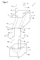
- FIG. 1 shows a geothermal probe 1 for a geothermal system with a probe head 2 and a Erdsondenfuß 3 according to an embodiment of the invention.
- the ground probe 1 also has two supply pipes 4a and 4b and two earth probe pipes 5a and 5b.
- the supply pipes 4a and 4b and the earth probe pipes 5a and 5b are also referred to below as pipelines.
- the Erdsondenfuß 3 has a main body 6a and two Erdsondenan everything 7a.
- the ground probe terminals 7a are arranged on an outer side 8 of the main body 6a. Inside the main body 6a, the ground probe connections 7a are connected in a fluid-conducting manner by means of a U-shaped connecting piece 9 (shown in dashed lines). At the two Erdsondenan Whyn 7a, the pipes 5a and 5b are connected.
- the ground probe head 2 has a main body 6b. On a lower side 10 of the main body 6b, two ground probe terminals 7b are arranged. On an upper side 11 of the main body 6b, two distributor terminals 12 are arranged. The ground probe terminals 7b are connected via connectors 13 in the interior of the main body 6b to the distribution terminals 12 (shown in phantom). At the Erdsondenaniere 7b the Erdsondenrohre 5a and 5b are connected. At the distribution terminals 12, the supply pipes 4a and 4b are connected.
- the ground probe 1 is arranged, for example, in a borehole which is drilled vertically in the ground (not shown). After the ground probe 1 has been introduced into such a well, this hole is usually filled with a thermally conductive material.
- a fluid in a flow direction 14 for example brine, so a glycol / water mixture, for receiving or emitting heat energy.
- the supply pipe 4a for example, from a heat pump, the fluid through the probe head 2 into the ground probe tube 5a and passed over the Erdsondenfuß 3 in the ground probe tube 5b.
- the Erdsondenrohre 5a and 5b is usually low compared to the ground temperature level of the fluid raised a higher temperature level by removing heat energy 15 from the earth. This raises the temperature of the fluid to a higher temperature level.
- the heat energy is delivered to a heat sink, for example, back to the heat pump.
- the heat pump raises the temperature level of the fluid under power, for example, to a predetermined temperature for heating purposes.
- thermal energy can also be released to the earth via the fluid.
- the fluid has a higher temperature level in comparison to the earth and releases heat energy to the earth via the pipes 5a and 5b.
- the earth is a heat sink.
- the fluid which now has a lower temperature level, flows via the supply pipe 4b, for example to a circulation pump, heat pump or cooling station.
- the terminals 7a, 7b and 12 of the Erdsondenfußes 3 and the Erdsondenkopfes 2 are universal terminals that are suitable for connection of pipes with different diameters. This makes it possible to use different pipelines with one and the same geothermal probes or Erdsonden tart. These modular terminals 7a, 7b and 12 are based on the Figures 2 and 3 described in detail.
- the pipes 4a, 4b, 5a and 5b are connected to the corresponding terminals 7a, 7b and 12 by means of a quick connection technique.
- the pipes 4a, 4b, 5a and 5b essentially a plastic material such as polyethylene or a composite material, which has a so-called "memory effect", ie a shape memory.
- This shape memory is particularly needed for quick connection techniques in which a pipe end of a pipe is widened by means of a special tool. Then the pipe end is attached to one of the connections. Due to the shape memory, the tube retracts to its original state or its original diameter. As a result, a fluid-tight and mechanically strong connection between the pipe and the connection is made.
- FIG. 2 shows a schematic side view of the Erdsondenfußes 3 of the ground probe 1.
- the Erdsondenfuß 3 has the main body 6a, on the upper side 8, the two Erdsondenan Actually 7a are arranged.
- Each ground probe terminal 7a has three size profiles 17a, 17b and 17c.
- Each size profile 17a to 17c has a diameter 18a, 18b and 18c, respectively.
- each size profile 17a to 17c has a surface-profiled pipe connection region 19a, 19b or 19c.
- Each earth probe connection 7a also has two diverging planes 20a and 20b, each representing an imaginary sectional plane through the earth probe connections 7a, in which each ground probe connection 7a can be cut to length.
- the Abfarn 20a and 20b are substantially in a plane perpendicular to the longitudinal axis of the ground probe terminals 7a level near a respective end piece 21a and 21b of the respective size profile 17a, 17b and 17c.
- the Erdsondenfuß additionally has a holding device 16 with an eyelet.
- About the holding device 16 can be Attach weights to the ground probe foot 3 so that it can easily be lowered into a borehole together with connected pipes 5a and 5b.
- the holding device 16 may alternatively have, for example, a bore or a thread for a screw connection.
- the three size profiles 17a to 17c are suitable for connecting pipes having a diameter of, for example, 25 mm, 32 mm and 40 mm.
- the two ground probe connections 7 a are connected in a fluid-conducting manner inside the main body 6 a via a U-shaped connecting piece 9.
- the ground probe terminals 7a and the main body 6a can be manufactured in one piece, for example by an injection molding process.
- a pipeline with a diameter of 25 mm can be connected to the ground probe connection 7a.
- the size profile 17a is cut off along the deviation plane 20a.
- the connection region 19b of the size profile 17b is terminally free. The cutting can be done for example with a dedicated pipe cutter or other tool.
- the connection region 19c can be exposed by terminating the two smaller size profiles 17a and 17b at the end, for example for a connection of a pipeline with a diameter of 40 mm.
- a pipe having substantially one of the three diameters 18a, 18b or 18c by means of a Quick connection technology to connect to the ground probe connection 7a.
- the ground probe terminals 7a may be closed, for example directly by injection molding. Alternatively, the ground probe terminals 7a may also be closed with an additional element, for example a cap. This prevents dirt from entering the probe foot before connecting pipes.
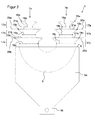
- FIG. 3 shows a schematic side view of a probe head 2 of the earth probe 1.
- the probe head 2 has the base body 6b, on the underside 10, the two ground probe terminals 7b are arranged.
- the two distributor ports 12 are arranged, wherein the second distributor port 12 of the illustrated distributor port 12 in the side view according to FIG FIG. 3 is covered.
- ground probe terminals 7b correspond to the ground probe terminals 7a according to the ground probe foot 3 of FIG. 2 and will not be described again.
- Each distributor port 12 has two size profiles 17d and 17e. Each size profile 17d and 17e has a diameter 18d and 18e, respectively. Furthermore, each size profile 17d and 17e has a profiled connection region 19d or 19e.
- Each manifold port 12 further includes a diverter 20c, which represents an imaginary sectional plane through the manifold port 12 in which the manifold port 12 can be cut to length. The Abberbene 20c lies essentially in a to Longitudinal axis of the manifold terminal 12 vertical plane near the end portion 21c of the size profile 17e.
- each distributor connection 12 is connected in each case to a ground probe connection 7b via a connecting piece 13 in accordance with the diameter 18e.
- the two size profiles 17d and 17e are suitable for connection of pipelines with a diameter of, for example, 32 mm and 40 mm, the size of the diameter being substantially corresponding to the size profiles 17a to 17c.
- the terminals 12 can also have 3 size profiles, analogous to the terminals 7a.
- the terminals 7b and 12 and the main body 6b can be produced in one piece, for example in an injection molding process.
- connection of pipes with, for example, 32 mm or 40 mm diameters to the distribution terminals 12 is analogous to the connection of pipes to the ground probe terminals 7a and 7b, as shown in the FIG. 2 has been described.
- the earth probe head 2 can be closed during manufacture to prevent the entry of dirt before connecting pipes.
- the Erdsondenfuß 3 and the Erdsondenkopf 2 are connected via two Erdsondenrohre 5 a and 5 b.
- both the Erdsondenfuß 3 and the Erdsondenkopf 2 each have further Erdsondenan say, which also by means of further Erdsondenrohre are connected.
- the main body 6a of Erdsondenfußes 3 has inside one or more appropriately adapted connectors for connecting the other pipes. Inside the main body 6b of the probe head 2, one or two earth probe connections are connected to a distributor connection 12 via a connecting piece.
Landscapes
- Engineering & Computer Science (AREA)
- Life Sciences & Earth Sciences (AREA)
- General Life Sciences & Earth Sciences (AREA)
- Sustainable Development (AREA)
- Sustainable Energy (AREA)
- Chemical & Material Sciences (AREA)
- Combustion & Propulsion (AREA)
- Mechanical Engineering (AREA)
- General Engineering & Computer Science (AREA)
- Geophysics And Detection Of Objects (AREA)
- Measuring Leads Or Probes (AREA)
Abstract
Description
- Die vorliegende Erfindung betrifft ein Erdsondenrohrverbindungsstück für eine modulare Erdsonde eines Geothermiesystems mit einem Grundkörper und wenigstens zwei Erdsondenanschlüssen. Die Erfindung betrifft des Weiteren einen Erdsondenfuß, einen Erdsondenkopf und eine Erdsonde für ein Geothermiesystem.
- Die Geothermie bezeichnet die in der Erdkruste gespeicherte Wärmeenergie, welche der Erde als Wärmequelle entzogen und genutzt werden kann. Dabei wird zwischen oberflächennaher (bis zu 400 m Tiefe) und tiefer Geothermie (mehr als 400 m Tiefe) unterschieden. Geothermiesysteme nutzen diese Erdwärmeenergie beispielsweise entweder direkt zum Heizen beziehungsweise Kühlen eines Gebäudes oder indirekt zur Erzeugung von Strom. Beispielsweise wird in einem oberflächennahen Geomethermiensystem die Wärme mit Hilfe von Erdwärmesonden der Erde entzogen und an eine Wärmesenke abgegeben, wobei die Wärme in einem Medium gespeichert ist. In der Regel entspricht die Wärmesenke einer Wärmepumpe, welche die gewonnene Erdwärme von einem niedrigen Temperaturniveau (beispielsweise 10 °C) unter Energiezufuhr auf ein erforderliches, beispielsweise ein für Heizzwecke bestimmtes, Temperaturniveau (beispielsweise 22 °C) anhebt. Umgekehrt wird beispielsweise beim Kühlen eines Gebäudes Wärme über die Erdsonden an die Erde abgegeben.
- Im Allgemeinen weist ein Erdsonden-Geothermiesystem mehrere Rohrleitungen auf, welche in der Regel in einem Bohrloch senkrecht zur Erdoberfläche in der Erde angeordnet sind. Das Bohrloch wird nach Verlegen der Rohre mit einem wärmeleitenden Material aufgefüllt. Somit ist es möglich, Wärme über die Rohrleitungen von der Erde aufzunehmen beziehungsweise Wärmeenergie über die Rohrleitungen an die Erde abzugeben.
- Es ist eine Aufgabe der Erfindung, Vorrichtungen zu beschreiben, welche einen einfachen und schnellen Aufbau eines Erdsonden-Geothermiesystems erlauben.
- Gemäß einem ersten Aspekt der Erfindung wird ein Erdsondenrohrverbindungsstück für eine modulare Erdsonde eines Geothermiesystems beschrieben. Das Erdsondenrohrverbindungsstück weist einen Grundkörper und wenigstens zwei Erdsondenanschlüsse, insbesondere für eine Schnellverbindungstechnik, auf. Die wenigstens zwei Erdsondenanschlüsse sind jeweils an einer Außenseite des Grundkörpers angeordnet und weisen wenigstens zwei unterschiedliche Größenprofile zum Anschluss von Rohrleitungen mit unterschiedlichen Querschnitten auf.
- Das Erdsondenrohrverbindungsstück gemäß dem ersten Aspekt der Erfindung sieht vor, dass Rohrleitungen mit unterschiedlichen Querschnitten angeschlossen werden können. Es ist deshalb nicht nötig, für jeden unterschiedlichen Querschnitt einer Rohrleitung ein jeweiliges, passendes Anschlussstück mit entsprechendem Querschnitt bereitzustellen. Bevorzugt sind die Anschlüsse für eine Schnellverbindungstechnik eingerichtet, womit beispielsweise eine schnelle Montage auf der Baustelle möglich ist. Des Weiteren ist dadurch beispielsweise auch eine Montage bei beengten Platzverhältnissen ermöglicht. Weiter ist kein spezielles Werkzeug zum Anschluss der Rohrleitungen und keine Schweißarbeit notwendig. Zudem werden durch solche universell verwendbaren Erdsondenrohrverbindungsstücke die Lagerhaltungskosten reduziert.
- Gemäß einer Ausgestaltungsform der Erfindung sind die Erdsondenanschlüsse derart ablängbar, dass ein oberflächig profilierter Anschlussbereich eines der wenigstens zwei unterschiedlichen Größenprofile endständig zum Anschluss an eine Rohrleitung mit entsprechendem Durchmesser mittels der Schnellverbindungstechnik freilegbar ist. Dadurch ist eine einstückige Herstellung der Anschlussbereiche für Rohrleitungen mit unterschiedlichen Durchmessern möglich.
- Gemäß einer weiteren Ausgestaltungsform der Erfindung sind der Grundkörper und die wenigstens zwei Erdsondenanschlüsse einstückig hergestellt. Dadurch können beispielsweise die Herstellungskosten reduziert werden.
- Gemäß einem zweiten Aspekt der Erfindung wird ein Erdsondenfuß mit einem Erdsondenrohrverbindungsstück gemäß dem ersten Aspekt der Erfindung beschrieben. Bei dem Erdsondenfuß sind die wenigstens zwei Erdsondenanschlüsse innerhalb des Grundkörpers fluidleitend, insbesondere durch ein U-förmiges Verbindungsstück, miteinander verbunden.
- Der Erdsondenfuß gemäß dem zweiten Aspekt der Erfindung verbindet im Inneren seines Grundkörpers die zwei Erdsondenanschlüsse. Dadurch können zwei über die Erdsondenanschlüsse angeschlossene Rohrleitungen über den Erdsondenfuß verbunden werden und beispielsweise in einem Bohrloch verlegt werden.
- Gemäß einem dritten Aspekt der Erfindung wird ein Erdsondenkopf beschrieben, welcher ein Erdsondenrohrverbindungsstück gemäß dem ersten Aspekt der Erfindung aufweist. Der Erdsondenkopf weist weiter zwei Verteileranschlüsse, insbesondere für eine Schnellverbindungstechnik, auf, die jeweils an einer Außenseite des Grundkörpers angeordnet sind und innerhalb des Grundkörpers jeweils mit wenigstens einem Erdsondenanschluss fluidleitend miteinander verbunden sind.
- Mittels eines Erdsondenkopfes gemäß dem dritten Aspekt der Erfindung können Rohrleitungen, die an den Erdsondenanschlüssen angeschlossen sind, mit Rohrleitungen verbunden werden, die an den zwei Verteileranschlüssen angeschlossen sind. Somit ist es möglich, dass ein Fluid, welches beispielsweise Wärmeenergie aufgenommen hat, über die Erdsondenanschlüsse an die Verteileranschlüsse zur Nutzbarmachung der Wärmeenergie weitergeleitet wird.
- Gemäß einer Ausgestaltungsform der Erfindung weisen die zwei Verteileranschlüsse jeweils wenigstens zwei unterschiedliche Größenprofile zum Anschluss von Rohrleitungen mit unterschiedlichen Querschnitten auf.
- Gemäß einer weiteren Ausgestaltungsform der Erfindung sind die zwei Verteileranschlüsse derart ablängbar, dass ein oberflächig profilierter Anschlussbereich eines der wenigstens zwei unterschiedlichen Größenprofile endständig zum Anschluss an eine Rohrleitung mit entsprechendem Durchmesser mittels der Schnellverbindungstechnik freilegbar ist.
- Gemäß einer weiteren Ausgestaltung der Erfindung sind der Grundkörper, die wenigstens zwei Erdsondenanschlüsse und die zwei Verteileranschlüsse einstückig hergestellt. Dies reduziert beispielsweise die Herstellungskosten.
- Gemäß einem vierten Aspekt der Erfindung wird eine Erdsonde für ein Geothermiesystem beschrieben, welche einen Erdsondenfuß gemäß dem zweiten Aspekt der Erfindung und einen Erdsondenkopf gemäß dem dritten Aspekt der Erfindung aufweist. Der Erdsondenfuß und der Erdsondenkopf sind über mindestens zwei Erdsondenrohre miteinander verbunden, wobei der Erdsondenfuß und der Erdsondenkopf jeweils mindestens zwei Anschlüsse aufweisen. Die Erdsondenrohre sind mittels einer Schnellverbindungstechnik mit den Anschlüssen des Erdsondenfußes und des Erdsondenkopfes verbunden.
- Die Erdsonde gemäß dem vierten Aspekt der Erfindung besitzt im Wesentlichen die gleichen Vorteile wie die Gegenstände der vorgenannten Aspekte der Erfindung. Die modulare Erdsonde ist für die Verwendung in einem Geothermiesystem geeignet und zeichnet sich durch ihre einfachen Anschlussmöglichkeiten und hohe Modularität aus. Dabei müssen nur wenige unterschiedliche Einzelkomponenten, insbesondere Erdsondenfüße beziehungsweise Erdsondenköpfe, unabhängig von Rohrdurchmessern der zu errichtenden Erdsonde bereitgehalten werden.
- Weitere vorteilhafte Ausgestaltungen der Erfindung sind in der nachfolgenden ausführlichen Beschreibung einer beispielhaften Erdsonde sowie den abhängigen Schutzansprüchen offenbart.
- Nachfolgend wird die Erfindung anhand der Erdsonde unter Bezugnahme auf die angehängten Figuren beschrieben. Unterschiedliche Instanzen gleichartiger Komponenten werden in den Figuren mit einem alphabetischen Suffix versehen, um diese besser unterscheiden zu können.
- In den Figuren zeigen:
- Figur 1
- eine schematische, perspektivische Darstellung einer Erdsonde gemäß einem ersten Ausführungsbeispiel der Erfindung,
- Figur 2
- eine schematische Seitenansicht eines Erdsondenfußes gemäß dem ersten Ausführungsbeispiel der Erfindung, und
- Figur 3
- eine schematische Seitenansicht eines Erdsondenkopfes gemäß dem ersten Ausführungsbeispiel der Erfindung.
-
Figur 1 zeigt eine Erdsonde 1 für ein Geothermiesystem mit einem Erdsondenkopf 2 und einem Erdsondenfuß 3 gemäß einem Ausführungsbeispiel der Erfindung. Die Erdsonde 1 weist weiterhin zwei Zuleitungsrohre 4a und 4b sowie zwei Erdsondenrohre 5a und 5b auf. Die Zuleitungsrohre 4a und 4b bzw. die Erdsondenrohre 5a und 5b werden nachfolgend auch als Rohrleitungen bezeichnet. - Der Erdsondenfuß 3 weist einen Grundkörper 6a und zwei Erdsondenanschlüsse 7a auf. Die Erdsondenanschlüsse 7a sind auf einer Außenseite 8 des Grundkörpers 6a angeordnet. Im Inneren des Grundkörpers 6a sind die Erdsondenanschlüsse 7a fluidleitend mittels eines U-förmigen Verbindungsstücks 9 (gestrichelt dargestellt) verbunden. An den beiden Erdsondenanschlüssen 7a sind die Rohrleitungen 5a beziehungsweise 5b angeschlossen.
- Der Erdsondenkopf 2 weist einen Grundkörper 6b auf. An einer Unterseite 10 des Grundkörpers 6b sind zwei Erdsondenanschlüsse 7b angeordnet. An einer Oberseite 11 des Grundkörpers 6b sind zwei Verteileranschlüsse 12 angeordnet. Die Erdsondenanschlüsse 7b sind über Verbindungsstücke 13 im Inneren des Grundkörpers 6b mit den Verteileranschlüssen 12 verbunden (gestrichelt dargestellt). An den Erdsondenanschlüsse 7b sind die Erdsondenrohre 5a beziehungsweise 5b angeschlossen. An den Verteileranschlüssen 12 sind die Zuleitungsrohre 4a beziehungsweise 4b angeschlossen.
- Die Erdsonde 1 ist beispielsweise in einem Bohrloch angeordnet, welches senkrecht in die Erde gebohrt ist (nicht dargestellt). Nachdem die Erdsonde 1 in ein solches Bohrloch eingebracht wurde, wird dieses Bohrloch in der Regel mit einem wärmeleitenden Material aufgefüllt. Innerhalb der Rohrleitungen 4a, 4b, 5a und 5b und den Verbindungsstücken 9 beziehungsweise 13 fließt ein Fluid in einer Flussrichtung 14, beispielsweise Sole, also ein Glykol-/Wasser-Gemisch, zur Aufnahme bzw. Abgabe von Wärmeenergie. Über das Zuleitungsrohr 4a wird, beispielsweise von einer Wärmepumpe, das Fluid über den Erdsondenkopf 2 in das Erdsondenrohr 5a und über den Erdsondenfuß 3 in das Erdsondenrohr 5b geleitet. Über die Erdsondenrohre 5a und 5b wird in der Regel das im Vergleich zur Erde niedrige Temperaturniveau des Fluids auf ein höheres Temperaturniveau angehoben, indem Wärmeenergie 15 der Erde entzogen wird. Dadurch wird die Temperatur des Fluids auf ein höheres Temperaturniveau angehoben. Über den Erdsondenkopf 2 und das Zuleitungsrohr 4b wird die Wärmeenergie an eine Wärmesenke abgegeben, beispielsweise zurück an die Wärmepumpe. Die Wärmepumpe hebt das Temperaturniveau des Fluids unter Energiezufuhr an, beispielsweise auf ein für Heizzwecke vorbestimmtes Temperaturniveau.
- Alternativ kann über das Fluid auch Wärmeenergie an die Erde abgegeben werden. Hierzu weist das Fluid ein im Vergleich zu der Erde höheres Temperaturniveau auf und gibt über die Rohrleitungen 5a und 5b Wärmeenergie an die Erde ab. In diesem Fall stellt die Erde eine Wärmesenke dar. Anschließend fließt das Fluid, welches nun ein niedrigeres Temperaturniveau aufweist, über das Zuleitungsrohr 4b ab, beispielsweise zu einer Umwälzpumpe, Wärmepumpe oder Kühlstation.
- Die Anschlüsse 7a, 7b und 12 des Erdsondenfußes 3 beziehungsweise des Erdsondenkopfes 2 sind universelle Anschlüsse, die zum Anschluss von Rohrleitungen mit unterschiedlichen Durchmessern geeignet sind. Dadurch ist es möglich, verschiedene Rohrleitungen mit ein und denselben Erdsondenköpfen beziehungsweise Erdsondenfüßen zu verwenden. Diese modularen Anschlüsse 7a, 7b und 12 werden anhand der
Figuren 2 und3 ausführlich beschrieben. - Die Rohrleitungen 4a, 4b, 5a und 5b sind mittels einer Schnellverbindungstechnik an die entsprechenden Anschlüsse 7a, 7b und 12 angeschlossen. Dazu weisen die Rohrleitungen 4a, 4b, 5a und 5b im Wesentlichen einen Kunststoffwerkstoff wie beispielsweise Polyethylen oder einen Verbundwerkstoff auf, welcher einen sogenannten "Memory Effekt", also ein Formgedächtnis, aufweist. Dieses Formgedächtnis ist besonders für Schnellverbindungstechniken von Nöten, bei welcher ein Rohrende einer Rohrleitung mit Hilfe eines speziellen Werkzeuges aufgeweitet wird. Anschließend wird das Rohrende auf einen der Anschlüsse aufgesteckt. Aufgrund des Formgedächtnisses zieht sich das Rohr auf seinen ursprünglichen Zustand beziehungsweise seinen ursprünglichen Durchmesser zurück. Dadurch wird eine fluiddichte und mechanisch feste Verbindung zwischen der Rohrleitung und dem Anschluss hergestellt.
-
Figur 2 zeigt eine schematische Seitenansicht des Erdsondenfußes 3 der Erdsonde 1. Der Erdsondenfuß 3 weist den Grundkörper 6a auf, auf dessen Oberseite 8 die zwei Erdsondenanschlüsse 7a angeordnet sind. Jeder Erdsondenanschluss 7a weist drei Größenprofile 17a, 17b und 17c auf. Jedes Größenprofil 17a bis 17c weist einen Durchmesser 18a, 18b beziehungsweise 18c auf. Weiter weist jedes Größenprofil 17a bis 17c einen oberflächig profilierten Rohranschlussbereich 19a, 19b beziehungsweise 19c auf. Jeder Erdsondenanschluss 7a weist zudem zwei Ablängebenen 20a und 20b auf, die jeweils eine gedachte Schnittebene durch die Erdsondenanschlüsse 7a darstellen, in der jeder Erdsondenanschluss 7a abgelängt werden kann. Die Ablängebenen 20a und 20b liegen dabei im Wesentlichen in einer zur Längsachse der Erdsondenanschlüsse 7a senkrechten Ebene nahe eines jeweiligen Endstücks 21a beziehungsweise 21b des jeweiligen Größenprofils 17a, 17b beziehungsweise 17c. - Der Erdsondenfuß weist zusätzlich eine Haltevorrichtung 16 mit einer Öse auf. Über die Haltevorrichtung 16 lassen sich Gewichte an den Erdsondenfuß 3 anbringen, um diesen zusammen mit angeschlossenen Rohrleitungen 5a und 5b leicht in einem Bohrloch versenken zu können. Die Haltevorrichtung 16 kann alternativ beispielsweise auch eine Bohrung oder ein Gewinde für eine Schraubverbindung aufweisen.
- Die drei Größenprofile 17a bis 17c sind zum Anschluss von Rohrleitungen mit einem Durchmesser von beispielsweise 25 mm, 32 mm und 40 mm geeignet. Entsprechend dem größten Durchmesser 18c sind die beiden Erdsondenanschlüsse 7a im Inneren des Grundkörpers 6a über ein U-förmiges Verbindungsstück 9 fluidleitend verbunden. Die Erdsondenanschlüsse 7a und der Grundkörper 6a können einstückig, beispielsweise in einem Spritzgussverfahren, hergestellt werden.
- Mittels des Größenprofils 17a kann beispielsweise eine Rohrleitung mit einem Durchmesser von 25 mm an den Erdsondenanschluss 7a angeschlossen werden. Soll beispielsweise eine Rohrleitung mit einem Durchmesser von 32 mm über das Größenprofil 17b an den Erdsondenanschluss 7a angeschlossen werden, so wird das Größenprofil 17a entlang der Ablängebene 20a abgetrennt. Damit liegt der Anschlussbereich 19b des Größenprofils 17b endständig frei. Das Ablängen kann beispielsweise mit einem dafür vorgesehenen Rohrschneider oder einem sonstigen Werkzeug erfolgen. Ebenso kann der Anschlussbereich 19c durch Ablängen der beiden kleineren Größenprofile 17a und 17b endständig, beispielsweise für einen Anschluss einer Rohrleitung mit einem Durchmesser von 40 mm, freigelegt werden. Somit ist es möglich, eine Rohrleitung mit im Wesentlichen einem der drei Durchmesser 18a, 18b oder 18c mittels einer Schnellverbindungstechnik an dem Erdsondenanschluss 7a anzuschließen.
- Bei der Herstellung können die Erdsondenanschlüsse 7a verschlossen sein, beispielsweise direkt im Spritzgussverfahren. Alternativ können die Erdsondenanschlüsse 7a auch mit einem zusätzlichen Element, beispielsweise einer Kappe, verschlossen sein. Damit wird verhindert, dass vor dem Anschließen von Rohrleitungen Schmutz in den Erdsondenfuß eintreten kann.
-
Figur 3 zeigt eine schematische Seitenansicht eines Erdsondenkopfes 2 der Erdsonde 1. Der Erdsondenkopf 2 weist den Grundkörper 6b auf, an dessen Unterseite 10 die zwei Erdsondenanschlüsse 7b angeordnet sind. Auf der Oberseite 11 des Grundkörpers 6b sind die zwei Verteileranschlüsse 12 angeordnet, wobei der zweite Verteileranschluss 12 von dem dargestellten Verteileranschluss 12 in der Seitenansicht gemäßFigur 3 verdeckt wird. - Die Erdsondenanschlüsse 7b entsprechen den Erdsondenanschlüssen 7a gemäß dem Erdsondenfuß 3 der
Figur 2 und werden nicht erneut beschrieben. - Jeder Verteileranschluss 12 weist zwei Größenprofile 17d und 17e auf. Jedes Größenprofil 17d und 17e weist einen Durchmesser 18d beziehungsweise 18e auf. Weiter weist jedes Größenprofil 17d und 17e einen profilierten Anschlussbereich 19d beziehungsweise 19e auf. Jeder Verteileranschluss 12 weist weiter eine Ablängebene 20c auf, die eine gedachte Schnittebene durch den Verteileranschluss 12 darstellt, in der der Verteileranschluss 12 abgelängt werden kann. Die Ablängebene 20c liegt dabei im Wesentlichen in einer zur Längsachse des Verteileranschlusses 12 senkrechten Ebene nahe des Endstücks 21c des Größenprofils 17e. Im Inneren des Grundkörpers 6b ist jeder Verteileranschluss 12 entsprechend dem Durchmesser 18e jeweils mit einem Erdsondenanschluss 7b über ein Verbindungsstück 13 verbunden.
- Die zwei Größenprofile 17d und 17e sind zum Anschluss von Rohrleitungen mit einem Durchmesser von beispielsweise 32 mm und 40 mm geeignet, wobei die Größe der Durchmesser im Wesentlichen korrespondierend zu den Größenprofilen 17a bis 17c ist. Die Anschlüsse 12 können alternativ auch 3 Größenprofile, analog zu den Anschlüssen 7a, aufweisen. Die Anschlüsse 7b und 12 sowie der Grundkörper 6b können einstückig, beispielsweise in einem Spritzgussverfahren hergestellt werden.
- Der Anschluss von Rohrleitungen mit beispielsweise 32 mm oder 40 mm Durchmessern an die Verteileranschlüsse 12 erfolgt analog zum Anschluss von Rohrleitungen an die Erdsondenanschlüsse 7a beziehungsweise 7b, wie anhand der
Figur 2 beschrieben wurde. - Analog zu dem Erdsondenfuß 3 gemäß der
Figur 2 kann der Erdsondenkopf 2 bei der Herstellung verschlossen werden, um den Eintritt von Schmutz vor dem Anschluss von Rohrleitungen zu vermeiden. - Wie anhand des Ausführungsbeispiels gemäß den
Figuren 1 bis 3 beschrieben wurde, werden der Erdsondenfuß 3 und der Erdsondenkopf 2 über zwei Erdsondenrohre 5a und 5b verbunden. Es ist allerdings auch möglich, dass sowohl der Erdsondenfuß 3 als auch der Erdsondenkopf 2 jeweils weitere Erdsondenanschlüsse aufweisen, die ebenfalls mittels weiterer Erdsondenrohre verbunden sind. Der Grundkörper 6a des Erdsondenfußes 3 weist im Inneren ein oder mehrere entsprechend angepasste Verbindungsstücke zum Verbinden der weiteren Rohrleitungen auf. Im Inneren des Grundkörpers 6b des Erdsondenkopfes 2 sind ein oder zwei Erdsondenanschlüsse mit einem Verteileranschluss 12 über ein Verbindungsstück verbunden. - Die in dem beschriebenen Ausführungsbeispiel darlegten Merkmale einer Erdsonde, eines Erdsondenkopfes und eines Erdsondenfußes können auf verschiedene Weise miteinander kombiniert werden, um die jeweils genannten Vorteile und/oder Funktionen zu verwirklichen.
-
- 1
- Erdsonde
- 2
- Erdsondenkopf
- 3
- Erdsondenfuß
- 4a, 4b
- Zuleitungsrohr
- 5a, 5b
- Erdsondenrohr
- 6a, 6b
- Grundkörper
- 7a, 7b
- Erdsondenanschluss
- 8
- Außenseite
- 9
- Verbindungsstück
- 10
- Unterseite
- 11
- Oberseite
- 12
- Verteileranschluss
- 13
- Verbindungsstück
- 14
- Flussrichtung
- 15
- Wärmequelle
- 16
- Haltevorrichtung
- 17a, 17b, 17c,
- Größenprofil
- 18a bis 18e
- Durchmesser
- 19a, 19b, 19c
- profilierter Anschlussbereich
- 20a, 20b, 20c
- Ablängebene
- 21a, 21b, 21c
- Endstück
Claims (9)
- Erdsondenrohrverbindungsstück für eine modulare Erdsonde (1) eines Geothermiesystems, aufweisend- einen Grundkörper (6a, 6b); und- wenigstens zwei Erdsondenanschlüsse (7a, 7b), insbesondere für eine Schnellverbindungstechnik, wobei die wenigstens zwei Erdsondenanschlüsse (7a, 7b) jeweils an einer Außenseite (8, 10) des Grundkörpers (6a, 6b) angeordnet sind und wenigstens zwei unterschiedliche Größenprofile (17a, 17b, 17c) zum Anschluss von Rohrleitungen (5a, 5b) mit unterschiedlichen Querschnitten aufweisen.
- Erdsondenrohrverbindungsstück nach Anspruch 1, bei welchem die wenigstens zwei Erdsondenanschlüsse (7a, 7b) derart ablängbar sind, dass ein oberflächig profilierter Anschlussbereich (19a, 19b, 19c) eines der wenigstens zwei unterschiedlichen Größenprofile (17a, 17b, 17c) endständig zum Anschluss an eine Rohrleitung (5a, 5b) mit entsprechendem Durchmesser (18a, 18b, 18c) mittels der Schnellverbindungstechnik freilegbar ist.
- Erdsondenrohrverbindungsstück nach einem der Ansprüche 1 oder 2, bei welchem der Grundkörper (6a, 6b) und die wenigstens zwei Erdsondenanschlüsse (7a, 7b) einstückig hergestellt sind.
- Erdsondenfuß (3), aufweisend
ein Erdsondenrohrverbindungsstück (16) nach einem der Ansprüche 1 bis 3, bei welchem die wenigstens zwei Erdsondenanschlüsse (7a) innerhalb des Grundkörpers (6a) fluidleitend, insbesondere durch ein U-förmiges Verbindungsstück (9), miteinander verbunden sind. - Erdsondenkopf (2), aufweisend
ein Erdsondenrohrverbindungsstück (16) nach einem der Ansprüche 1 bis 3, weiter aufweisend zwei Verteileranschlüsse (12) für eine Schnellverbindungstechnik, wobei die zwei Verteileranschlüsse (12) jeweils an einer Außenseite (11) des Grundkörpers (6b) angeordnet und innerhalb des Grundkörpers (6b) jeweils mit wenigstens einem Erdsondenanschluss (7b) fluidleitend miteinander verbunden sind. - Erdsondenkopf (2) nach Anspruch 5, bei welchem die zwei Verteileranschlüsse (12) jeweils wenigstens zwei unterschiedliche Größenprofile (17d, 17e) zum Anschluss von Rohrleitungen (4a, 4b) mit unterschiedlichen Querschnitten aufweisen.
- Erdsondenkopf (2) nach Anspruch 6, bei welchem die zwei Verteileranschlüsse (12) derart ablängbar sind, dass ein oberflächig profilierter Anschlussbereich (19d, 19e) eines der wenigstens zwei unterschiedlichen Größenprofile (17d, 17e) endständig zum Anschluss an eine Rohrleitung (4a, 4b) mit entsprechendem Durchmesser (18d, 18e) mittels der Schnellverbindungstechnik freilegbar ist.
- Erdsondenkopf (2) nach einem der Ansprüche 5 bis 7, bei welchem der Grundkörper (6b), die wenigstens zwei Erdsondenanschlüsse (7b) und die zwei Verteileranschlüsse (12) einstückig hergestellt sind.
- Erdsonde (1) für ein Geothermiesystem, aufweisend einen Erdsondenfuß (3), insbesondere nach dem Anspruch 4, und einen Erdsondenkopf (2), insbesondere nach einem der Ansprüche 5 bis 8, die über mindestens zwei Erdsondenrohre (5a, 5b) miteinander verbunden sind, wobei der Erdsondenfuß (3) und der Erdsondenkopf (2) jeweils mindestens zwei Anschlüsse (7a, 7b) aufweisen und die Erdsondenrohre (5a, 5b) mittels einer Schnellverbindungstechnik mit den Anschlüssen (7a, 7b) des Erdsondenfußes (3) und des Erdsondenkopfes (2) verbunden sind.
Applications Claiming Priority (1)
| Application Number | Priority Date | Filing Date | Title |
|---|---|---|---|
| DE202012103844.7U DE202012103844U1 (de) | 2012-10-08 | 2012-10-08 | Erdsondenrohrverbindungsstück für eine modulare Erdsonde eines Geothermiesystems, Erdsondenfuß, Erdsondenkopf und Erdsonde für ein Geothermiesystem |
Publications (2)
| Publication Number | Publication Date |
|---|---|
| EP2716996A2 true EP2716996A2 (de) | 2014-04-09 |
| EP2716996A3 EP2716996A3 (de) | 2014-10-15 |
Family
ID=49293463
Family Applications (1)
| Application Number | Title | Priority Date | Filing Date |
|---|---|---|---|
| EP13185973.8A Withdrawn EP2716996A3 (de) | 2012-10-08 | 2013-09-25 | Erdsondenrohrverbindungsstück für eine modulare Erdsonde eines Geothermiesystems, Erdsondenfuß, Erdsondenkopf und Erdsonde für ein Geothermiesystem |
Country Status (2)
| Country | Link |
|---|---|
| EP (1) | EP2716996A3 (de) |
| DE (1) | DE202012103844U1 (de) |
Family Cites Families (15)
| Publication number | Priority date | Publication date | Assignee | Title |
|---|---|---|---|---|
| DE3244496A1 (de) * | 1982-11-29 | 1984-05-30 | Andreas Dr.-Ing. 1000 Berlin Hampe | Erdwaermetauscherelement |
| US4538673A (en) * | 1984-05-02 | 1985-09-03 | Geo-Systems, Inc. | Drilled well series and paralleled heat exchange systems |
| EP0582118A1 (de) * | 1992-08-06 | 1994-02-09 | Sacac Hergiswil Ag | Erdsondengebilde, Distanzhalter für Erdsondengebilde, mindestens einteiliger Erdpfahl mit Erdsonde, Erdwärmegewinnungsanlage sowie deren Verfahren |
| US6250371B1 (en) * | 1995-09-12 | 2001-06-26 | Enlink Geoenergy Services, Inc. | Energy transfer systems |
| JP2000161807A (ja) * | 1998-11-24 | 2000-06-16 | Matsushita Refrig Co Ltd | 空気調和機 |
| CH697102A5 (de) * | 1999-03-16 | 2008-04-30 | Haka Gerodur Ag | Verbindungsstück aus thermoplastischem Kunststoff für Rohrleitungen einer Erdsondenanlage. |
| DE20021105U1 (de) * | 2000-10-02 | 2001-06-13 | Frank GmbH, 64546 Mörfelden-Walldorf | Sondenfuß |
| FR2822519B1 (fr) * | 2001-03-26 | 2004-04-09 | Exel Ind | Raccord pour tuyau |
| WO2003064915A1 (fr) * | 2002-01-31 | 2003-08-07 | Tecfor Sa | Raccord pour sonde geothermique |
| WO2008106699A1 (de) * | 2007-03-06 | 2008-09-12 | A & S Umwelttechnologie Ag | Erdsondenanlage |
| DE202008012453U1 (de) * | 2008-09-18 | 2010-02-11 | Rehau Ag + Co | Erdwärmesonde |
| DE102010007662A1 (de) * | 2010-02-10 | 2011-08-11 | Ledwon, Anton, 53842 | Geothermieverteiler |
| EP2363269A1 (de) * | 2010-03-02 | 2011-09-07 | Gunar Kloss | Verbindungsstück aus thermoplastischem Kunststoff |
| EP2395301B1 (de) * | 2010-06-14 | 2016-03-30 | HAKA.Gerodur AG | Verbindungsstück für Rohrleitungen einer Erdwärmesondenanlage |
| DE202012103415U1 (de) * | 2012-09-07 | 2012-09-24 | Uponor Innovation Ab | Schachtsystem für ein Geothermiesystem und Geothermiesystem |
-
2012
- 2012-10-08 DE DE202012103844.7U patent/DE202012103844U1/de not_active Expired - Lifetime
-
2013
- 2013-09-25 EP EP13185973.8A patent/EP2716996A3/de not_active Withdrawn
Non-Patent Citations (1)
| Title |
|---|
| None |
Also Published As
| Publication number | Publication date |
|---|---|
| DE202012103844U1 (de) | 2014-01-09 |
| EP2716996A3 (de) | 2014-10-15 |
Similar Documents
| Publication | Publication Date | Title |
|---|---|---|
| EP0582118A1 (de) | Erdsondengebilde, Distanzhalter für Erdsondengebilde, mindestens einteiliger Erdpfahl mit Erdsonde, Erdwärmegewinnungsanlage sowie deren Verfahren | |
| DE102015006093B3 (de) | Vorrichtung und Verfahren zum Fördern von Wasser aus einem Brunnen | |
| EP0017783A1 (de) | Vorrichtung zur Nutzung der Erdwärme und Verfahren zur Herstellung dieser Vorrichtung | |
| DE102007002606A1 (de) | Sondenfuß für eine Erdwärmesonde | |
| EP2060860B1 (de) | Geothermiesonde und Verfahren zu deren Installation | |
| EP2281154A2 (de) | Modular aufgebauter sondenfuss und seine komponenten | |
| EP2706308B1 (de) | Erdwärmesonde | |
| DE202022102819U1 (de) | Erdwärmetauscher | |
| DE202007000763U1 (de) | Sondenfuß für eine Erdwärmesonde | |
| WO2011015341A1 (de) | Einbauvorrichtung für eine erdwärmesonde | |
| DE202012103844U1 (de) | Erdsondenrohrverbindungsstück für eine modulare Erdsonde eines Geothermiesystems, Erdsondenfuß, Erdsondenkopf und Erdsonde für ein Geothermiesystem | |
| WO2007088072A1 (de) | Verbindung zwischen der stirnseite eines kunststoffrohres und einem kunstoffkörper | |
| WO2011015342A1 (de) | Erdwärmesondeneinbauvorrichtung | |
| EP2706302A2 (de) | Schachtsystem für ein Geothermiesystem und Geothermiesystem | |
| EP3502584B1 (de) | Wärmeaustauschsonde | |
| DE202007000764U1 (de) | Sondenfuß für eine Erdwärmesonde | |
| DE102016103922A1 (de) | Flächenheiz- und Flächenkühlsystem | |
| DE102017120206A1 (de) | Tragwerkelement, Tragwerksystem und Gebäude | |
| DE2106046C3 (de) | Verfahren zum Einbetten einer Leitung in den Boden eines Gewässers | |
| DE102014223394A1 (de) | Verlegbares Kanalrohrsegment | |
| DE3244496A1 (de) | Erdwaermetauscherelement | |
| WO2013091853A1 (de) | Erdwärmesondenanordnung | |
| DE202009015391U1 (de) | Sondenkopf | |
| EP3431702B1 (de) | Verfahren und vorrichtung zur grabenlosen verlegung eines kabels oder rohres in einem boden | |
| DE10251080B4 (de) | Verfahren zum Verlegen einer Rohrleitung und Verlegeeinrichtung zur Durchführung des Verfahrens |
Legal Events
| Date | Code | Title | Description |
|---|---|---|---|
| PUAI | Public reference made under article 153(3) epc to a published international application that has entered the european phase |
Free format text: ORIGINAL CODE: 0009012 |
|
| AK | Designated contracting states |
Kind code of ref document: A2 Designated state(s): AL AT BE BG CH CY CZ DE DK EE ES FI FR GB GR HR HU IE IS IT LI LT LU LV MC MK MT NL NO PL PT RO RS SE SI SK SM TR |
|
| AX | Request for extension of the european patent |
Extension state: BA ME |
|
| PUAL | Search report despatched |
Free format text: ORIGINAL CODE: 0009013 |
|
| AK | Designated contracting states |
Kind code of ref document: A3 Designated state(s): AL AT BE BG CH CY CZ DE DK EE ES FI FR GB GR HR HU IE IS IT LI LT LU LV MC MK MT NL NO PL PT RO RS SE SI SK SM TR |
|
| AX | Request for extension of the european patent |
Extension state: BA ME |
|
| RIC1 | Information provided on ipc code assigned before grant |
Ipc: F16L 33/30 20060101ALI20140909BHEP Ipc: F16L 37/56 20060101ALI20140909BHEP Ipc: F16L 25/14 20060101ALI20140909BHEP Ipc: F16L 41/03 20060101ALI20140909BHEP Ipc: F24J 3/08 20060101AFI20140909BHEP |
|
| 17P | Request for examination filed |
Effective date: 20150415 |
|
| RBV | Designated contracting states (corrected) |
Designated state(s): AL AT BE BG CH CY CZ DE DK EE ES FI FR GB GR HR HU IE IS IT LI LT LU LV MC MK MT NL NO PL PT RO RS SE SI SK SM TR |
|
| 17Q | First examination report despatched |
Effective date: 20180814 |
|
| STAA | Information on the status of an ep patent application or granted ep patent |
Free format text: STATUS: THE APPLICATION HAS BEEN WITHDRAWN |
|
| 18W | Application withdrawn |
Effective date: 20181108 |