EP2716824A2 - Hose, in particular a shower hose - Google Patents
Hose, in particular a shower hose Download PDFInfo
- Publication number
- EP2716824A2 EP2716824A2 EP13183680.1A EP13183680A EP2716824A2 EP 2716824 A2 EP2716824 A2 EP 2716824A2 EP 13183680 A EP13183680 A EP 13183680A EP 2716824 A2 EP2716824 A2 EP 2716824A2
- Authority
- EP
- European Patent Office
- Prior art keywords
- hose
- metal
- tube
- connecting piece
- sleeve
- Prior art date
- Legal status (The legal status is an assumption and is not a legal conclusion. Google has not performed a legal analysis and makes no representation as to the accuracy of the status listed.)
- Withdrawn
Links
Images

Classifications
-
- E—FIXED CONSTRUCTIONS
- E03—WATER SUPPLY; SEWERAGE
- E03C—DOMESTIC PLUMBING INSTALLATIONS FOR FRESH WATER OR WASTE WATER; SINKS
- E03C1/00—Domestic plumbing installations for fresh water or waste water; Sinks
- E03C1/02—Plumbing installations for fresh water
- E03C1/025—Water supply lines as such, e.g. shower hoses
-
- F—MECHANICAL ENGINEERING; LIGHTING; HEATING; WEAPONS; BLASTING
- F16—ENGINEERING ELEMENTS AND UNITS; GENERAL MEASURES FOR PRODUCING AND MAINTAINING EFFECTIVE FUNCTIONING OF MACHINES OR INSTALLATIONS; THERMAL INSULATION IN GENERAL
- F16L—PIPES; JOINTS OR FITTINGS FOR PIPES; SUPPORTS FOR PIPES, CABLES OR PROTECTIVE TUBING; MEANS FOR THERMAL INSULATION IN GENERAL
- F16L11/00—Hoses, i.e. flexible pipes
- F16L11/14—Hoses, i.e. flexible pipes made of rigid material, e.g. metal or hard plastics
- F16L11/16—Hoses, i.e. flexible pipes made of rigid material, e.g. metal or hard plastics wound from profiled strips or bands
-
- F—MECHANICAL ENGINEERING; LIGHTING; HEATING; WEAPONS; BLASTING
- F16—ENGINEERING ELEMENTS AND UNITS; GENERAL MEASURES FOR PRODUCING AND MAINTAINING EFFECTIVE FUNCTIONING OF MACHINES OR INSTALLATIONS; THERMAL INSULATION IN GENERAL
- F16L—PIPES; JOINTS OR FITTINGS FOR PIPES; SUPPORTS FOR PIPES, CABLES OR PROTECTIVE TUBING; MEANS FOR THERMAL INSULATION IN GENERAL
- F16L33/00—Arrangements for connecting hoses to rigid members; Rigid hose connectors, i.e. single members engaging both hoses
- F16L33/01—Arrangements for connecting hoses to rigid members; Rigid hose connectors, i.e. single members engaging both hoses adapted for hoses having a multi-layer wall
-
- F—MECHANICAL ENGINEERING; LIGHTING; HEATING; WEAPONS; BLASTING
- F16—ENGINEERING ELEMENTS AND UNITS; GENERAL MEASURES FOR PRODUCING AND MAINTAINING EFFECTIVE FUNCTIONING OF MACHINES OR INSTALLATIONS; THERMAL INSULATION IN GENERAL
- F16L—PIPES; JOINTS OR FITTINGS FOR PIPES; SUPPORTS FOR PIPES, CABLES OR PROTECTIVE TUBING; MEANS FOR THERMAL INSULATION IN GENERAL
- F16L33/00—Arrangements for connecting hoses to rigid members; Rigid hose connectors, i.e. single members engaging both hoses
- F16L33/24—Arrangements for connecting hoses to rigid members; Rigid hose connectors, i.e. single members engaging both hoses with parts screwed directly on or into the hose
Definitions
- the invention relates to a hose, in particular a shower hose, according to the preamble of claim 1 and a connection device for connecting such a hose to a fitting, a shower head or the like.
- a hose of the present type accordingly comprises an inner tube of elastomeric material, in which the fluid, usually water, is guided.
- the fluid usually water
- this is guided in a helically wound metal tube.
- this metal hose can be loosely wound with gaps between the individual windings, or relatively tightly and with windings that interlock with one another.
- this is finally provided with a plastic sheath.
- a hose of the present type is provided at least one of its ends with a connection device, the front side a connection flange for connecting the hose a fitting or the like.
- the connecting device must ensure on the one hand that a mechanically resistant and durable connection can be produced which, in particular, withstands high pull-out forces.
- the connection device must be fluid-tight for a long time and in this case withstand the prevailing internal pressures and any pressure pulses.
- connection devices have an inner sleeve and an outer sleeve, the inner sleeve being located inside the inner tube and usually pressed into it, for example by having a conical shape, and the outer sleeve being on the outside of the metal tube his sheath sits.
- the inner sleeve ensures the fluid-tightness of the connection by continuing at the front end into the connecting flange in known solutions.
- the connection flange then seals the interior of the inner sleeve against the fitting with its frontal sealing surface.
- the outer sleeve ensures mechanical stabilization of the connection device, as it protects the area of the connection device against kinking of the hose.
- An example of a hose and a connection device of this known type can be found in the EP 1 956 149 A1 ,
- the connecting flange of the connecting device is part of the inner sleeve, and this inner sleeve is seated in the inner tube of elastomeric material, pull-out forces acting on the connecting device, introduced into the inner tube.
- this is not optimal, because the inner tube is not designed for high mechanical loads.
- the present invention is therefore based on the object, a hose and a connection device of the type mentioned in such a way that an improved pull-out protection is given.
- connection flange is part of a separate connection piece which sits between the inner tube and the metal tube and the mechanical Forces from the flange preferably directly, and in any case introduces a significant part of the metal hose.
- the invention further provides that the inner sleeve, the connecting piece and the outer sleeve overlap in a radial projection at least partially, these components stabilize each other. It is thus also possible, for example, that the inner sleeve - especially if it is conical or with a plurality of conical surfaces - pushes the inner tube radially outward against the connector and this against the metal tube, the outer sleeve as an optional counter bearing against widening of the metal hose can act. This supports both the mechanical strength and the fluid tightness of the connection.
- connection does not always require a one-piece, uninterrupted connection between the connection flange and the inner sleeve. Because according to the present invention sits the end of the inner tube between the inner sleeve and the connecting piece, preferably with a radial clamping force, so that the space between the inner sleeve and the connecting piece is sealed fluid-tight.
- the connecting piece continues according to the invention end face in the connecting flange, a fluid-tight transition between the sealing surface of the connecting flange and the interior of the inner sleeve is ensured as a result, even if the inner sleeve, as is preferably the case in the present invention, not firmly connected to the connector or the flange.
- the inner sleeve is pressed into the inner tube. It then presses it substantially radially against the connecting piece, whereby the mentioned sealing effect is ensured even in the long term and under high mechanical stress as well as possible high internal pressures or pressure pulses.
- the inner sleeve continues the end face in a radially outwardly oriented collar, which covers the front side in axial projection part of the connector and preferably with the connection flange of the connector frontally forms a common radial plane.
- the connecting piece can be provided with threaded ridges with which the connecting piece can be screwed into the windings of the metal hose.
- the outside arranged on the circumference of the connecting piece threaded ridges engage here from the inside into the helical extending spaces of the individual windings of the metal tube.
- the outer sleeve of the connecting device has threaded ridges, with which it can be screwed onto the windings of the metal hose.
- the connecting piece and the outer sleeve of the connecting device between them form an annular space for receiving the metal tube together with sheath.
- This annulus is closed at the end to form an axial stop for the end face of the metal tube.
- the formation of the annular space is particularly advantageous, in particular because such a penetration of moisture on the end face of the metal tube between these and its sheath is prevented.
- this is regularly exposed to a wet environment, so that there is a risk of penetration of ambient water between the metal hose and the sheath.
- this must be prevented because this results in discoloration of the metal tube and possibly corrosion and mold, which would run counter to the impression of a high-quality product in the medium to long term.
- said seal is made by inserting a sealant adhesive into the annulus between the fitting and the outer sleeve.
- a sealant adhesive is that it can form a material connection with the sheath of the metal tube, which ensures a mechanically particularly resistant and long-term stable seal.
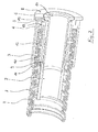
- FIG. 1 is shown in a schematic perspective sectional view of a first embodiment of an inventively designed hose or a connecting device according to the invention. It is a shower hose with a metal hose 1, an inner tube 2 made of elastomeric material and a plastic sheath. 7
- the metal tube 1 is a winding tube whose individual helically wound turns consist of a folded profile.
- the folded profile has been hooked into each other during winding of the tube, so that the turns of the metal tube 2 engage in a form-fitting manner.
- the sheath 7 consists of a thin, very tight applied to the metal tube 1, elastic plastic. Because of his only one thin-layered form he does not limit the mobility of the metal tube 1 and is barely recognizable in the figures.
- the inner tube 2 is made of a rubber-like, elastomeric material for conducting the generally warm between 30 ° C and 40 ° C provided for showering water.
- the attached at the end of the illustrated hose 1, 2, 7 connecting device consists in the present embodiment of an inner sleeve 6, a connector 5, the front side continues a connecting flange 8, an outer sleeve 3 and a seal 4th
- the inner sleeve 6 has a clear inner cross section which corresponds approximately to the clear inner cross section of the inner tube 2. Correspondingly, when the inner sleeve 6 was pressed in, the inner tube 2 had to be widened radially in order to rest on its outer circumference, as shown.
- the inner sleeve 6 is further provided with a plurality of staggered conical surfaces 9, which are axially arranged one behind the other and sawtooth-shaped, whereby, in addition to the radially acting elastic restoring force of the inner tube 2, an effective pull-out protection of the inner sleeve 6 from the inner tube 2 results.
- the connecting piece 5 is provided on its outer circumference with threaded ridges 10, which engage in corresponding, internal gaps between the individual windings of the metal tube 1. Since the metal tube 1 is helically wound, the connecting piece 5 can be screwed into the metal tube 1 with the aid of its threaded struts 10. The result is in FIG. 1 represented: The connector 5 is positively seated in the metal tube 1 and thus can initiate extraction forces directly into the metal tube 1. On the face side, the connecting piece 5 continues into the connecting flange 8 through a radially outwardly directed projection. Any forces that want to pull the hose from a (not shown) fitting, attack on Connection flange 8 and are thus introduced by means of the threaded ridge 10 substantially directly into the metal tube 1.
- the outer sleeve 3 is finally arranged.
- This has on its inner surface threaded ridges 11, which engage in the also present on the outer circumference of the metal tube 1 spaces between the individual windings and the outer sleeve 3 set axially form-fitting manner on the metal tube 1.
- a screwing of the outer sleeve 3 from the front side is possible.
- annular space 12 is formed, which receives the metal hose 1 together with its sheath 7.
- the annular space 12 is closed at the front by the outer sleeve 3 and the connecting piece 5 touch radially there.
- a stop 13 is formed for the front end of the metal tube 1, wherein in the present embodiment also a seal 4 between the stop 13 and the front end of the metal tube 1 is arranged.
- This seal 4 ensures that no moisture can reach the front between the metal hose 1 and its sheath 7. This is effected not only by a mechanical sealing effect of the seal 4, but also by a cohesive connection of the seal 4 with the sheath 7, since the seal 4 has been made with a two-component sealant adhesive.
- the procedure is as follows: First, the outer sleeve 3 is screwed onto the illustrated end of the metal tube 1 and its sheath 7 and the seal 4 introduced as a sealant adhesive. Then, the connecting piece 5 is screwed with its connecting flange 8 in the metal tube 1 until the connecting flange 8 abuts against the outer sleeve 3. As the last component, the inner sleeve 6 is pressed into the inner tube 2 until a front side radially outwardly continuing collar 14 of the inner sleeve 6 with the connecting flange 8 forms a common radial plane.
- the outer sleeve 3 acts here as an abutment that amplifies the counterforce of the connector 5 against radial expansion.
- the inner tube 2 is squeezed with a high, permanent radial force between the inner sleeve 6 and the connecting piece 5 so that it fills the annular space between the inner sleeve 6 and the connecting piece 5 in a sealing manner.
- the fluid transported in the inner tube 2 can thus, despite it being able to penetrate between the collar 14 and the connecting flange 8 into the annular space between the inner sleeve 6 and the connecting piece 5, be sealed to the outside.
- FIG. 2 illustrated embodiment differs from the in FIG. 1 shown embodiment only by a broader design of the collar 14 of the inner sleeve 6 and a corresponding modification of the transition of the connector 5 in the connection flange 8. All other parts of the hose shown and the connection device shown are formed identically, which is why identical reference numerals are used and the corresponding Description to FIG. 1 is referenced.
- the radially outwardly oriented collar 14 of the inner sleeve 6 is widened so that it, as seen in axial projection, a part of the connector 5 covers the front side.
- the transition of the connecting piece 5 in the connecting flange 8 has a corresponding recess 15, which forms a kind of stop for the collar 14 of the inner sleeve 6. This ensures, on the one hand, that the collar 14 and the connecting flange 8 form a common radial plane on the front side, and on the one hand other that the inner sleeve 6 takes over a part of the pull-out protection, since it is due to the recess 15 in a position to initiate pull-out forces acting on the connection flange 8, in the inner tube 2.
Abstract
Description
Die Erfindung betrifft einen Schlauch, insbesondere einen Brauseschlauch, nach dem Oberbegriff des Anspruchs 1 sowie eine Anschlussvorrichtung zum Anschließen eines solchen Schlauchs an eine Armatur, einen Brausekopf oder dergleichen.The invention relates to a hose, in particular a shower hose, according to the preamble of claim 1 and a connection device for connecting such a hose to a fitting, a shower head or the like.
Ein Schlauch der vorliegenden Art umfasst demnach einen Innenschlauch aus elastomerem Material, in dem das Fluid, in der Regel Wasser, geführt wird. Um die mechanische Stabilität des elastomeren Innenschlauchs zu verbessern, ist dieser in einem helixförmig gewickelten Metallschlauch geführt. Dieser Metallschlauch kann, je nach Anwendungsfall, locker mit Zwischenräumen zwischen den einzelnen Windungen, oder aber relativ dicht sowie mit Wicklungen gewickelt sein, die sich ineinander verhaken. Um den Metallschlauch in der feuchten Umgebung, in der ein Schlauch der vorliegenden Art üblicherweise benutzt wird, vor Korrosion und Schmutzablagerungen zu schützen, ist dieser schließlich mit einer Kunststoff-Ummantelung versehen.A hose of the present type accordingly comprises an inner tube of elastomeric material, in which the fluid, usually water, is guided. In order to improve the mechanical stability of the elastomeric inner tube, this is guided in a helically wound metal tube. Depending on the application, this metal hose can be loosely wound with gaps between the individual windings, or relatively tightly and with windings that interlock with one another. In order to protect the metal hose in the humid environment, in which a hose of the present type is commonly used to protect against corrosion and dirt deposits, this is finally provided with a plastic sheath.
Um den Schlauch an seinen Enden anschließen zu können, im Falle eines Brauseschlauchs also einerseits an einer Armatur und andererseits an einem Brausekopf, ist ein Schlauch der vorliegenden Art an mindestens einem seiner Enden mit einer Anschlussvorrichtung versehen, die stirnseitig einen Anschlussflansch zum Anschließen des Schlauchs an eine Armatur oder dergleichen aufweist. Die Anschlussvorrichtung muss hierbei einerseits gewährleisten, dass eine mechanisch widerstandsfähige und dauerhafte Verbindung hergestellt werden kann, die insbesondere hohen Auszugskräften Stand hält. Andererseits muss die Anschlussvorrichtung langzeitstabil fluiddicht sein und hierbei den herrschenden Innendrücken und eventuellen Druckpulsen Stand halten.In order to connect the hose at its ends, in the case of a shower hose on the one hand to a fitting and on the other hand to a shower head, a hose of the present type is provided at least one of its ends with a connection device, the front side a connection flange for connecting the hose a fitting or the like. On the one hand, the connecting device must ensure on the one hand that a mechanically resistant and durable connection can be produced which, in particular, withstands high pull-out forces. On the other hand, the connection device must be fluid-tight for a long time and in this case withstand the prevailing internal pressures and any pressure pulses.
Zur Erfüllung dieser Anforderungen weisen Anschlussvorrichtungen nach dem Stand der Technik eine Innenhülse und eine Außenhülse auf, wobei die Innenhülse im Inneren des Innenschlauchs sitzt und üblicherweise in diesen eingepresst ist, beispielsweise indem sie eine konische Form aufweist, und wobei die Außenhülse außen auf dem Metallschlauch und seiner Ummantelung sitzt. Die Innenhülse gewährleistet die Fluiddichtheit der Verbindung, indem sie sich bei bekannten Lösungen stirnseitig in den Anschlussflansch fortsetzt. Der Anschlussflansch dichtet dann mit seiner stirnseitigen Dichtfläche das Innere der Innenhülse gegen die Armatur ab. Die Außenhülse sorgt für eine mechanische Stabilisierung der Anschlussvorrichtung, da sie den Bereich der Anschlussvorrichtung gegen ein Abknicken des Schlauchs schützt. Ein Beispiel für einen Schlauch und eine Anschlussvorrichtung dieser bekannten Art findet sich in der
Dadurch, dass im Stand der Technik der Anschlussflansch der Anschlussvorrichtung Teil der Innenhülse ist, und diese Innenhülse im Innenschlauch aus elastomerem Material sitzt, werden Auszugskräfte, die auf die Anschlussvorrichtung wirken, in den Innenschlauch eingeleitet. Dies ist allerdings nicht optimal, denn der Innenschlauch ist für hohe mechanische Belastungen nicht ausgelegt.Due to the fact that in the prior art, the connecting flange of the connecting device is part of the inner sleeve, and this inner sleeve is seated in the inner tube of elastomeric material, pull-out forces acting on the connecting device, introduced into the inner tube. However, this is not optimal, because the inner tube is not designed for high mechanical loads.
Der vorliegenden Erfindung liegt daher die Aufgabe zugrunde, einen Schlauch und eine Anschlussvorrichtung der eingangs genannten Art solcherart weiterzubilden, dass eine verbesserte Auszugssicherung gegeben ist.The present invention is therefore based on the object, a hose and a connection device of the type mentioned in such a way that an improved pull-out protection is given.
Gelöst ist diese Aufgabe durch einen Schlauch mit den Merkmalen des Anspruchs 1 sowie durch eine Anschlussvorrichtung mit den Merkmalen des Anspruchs 11. Bevorzugte Ausgestaltungen und Weiterbildungen des erfindungsgemäßen Schlauchs finden sich in den Ansprüchen 2 bis 10.This problem is solved by a hose with the features of claim 1 and by a connection device with the features of
Gemäß der vorliegenden Erfindung werden die Innenhülse und der stirnseitige Anschlussflansch nicht mehr als ein einziges integriertes Bauteil ausgebildet, sondern der Anschlussflansch ist Teil eines separaten Anschlussstücks, das zwischen dem Innenschlauch und dem Metallschlauch sitzt und die mechanischen Kräfte vom Anschlussflansch vorzugsweise direkt, und jedenfalls zu einem signifikanten Teil in den Metallschlauch einleitet.According to the present invention, the inner sleeve and the end-side connection flange are no longer formed as a single integrated component, but the connection flange is part of a separate connection piece which sits between the inner tube and the metal tube and the mechanical Forces from the flange preferably directly, and in any case introduces a significant part of the metal hose.
Da erfindungsgemäß ferner vorgesehen ist, dass sich die Innenhülse, das Anschlussstück und die Außenhülse in einer radialen Projektion zumindest bereichsweise überlappen, stabilisieren sich diese Bauteile gegenseitig. Es ist so auch beispielsweise möglich, dass die Innenhülse - insbesondere dann, wenn sie konisch oder mit mehreren konischen Flächen ausgebildet ist - den Innenschlauch radial nach außen gegen das Anschlussstück und dieses gegen den Metallschlauch drückt, wobei die Außenhülse als gegebenenfalls notwendiges Gegenlager gegen ein Aufweiten des Metallschlauchs fungieren kann. Dies unterstützt sowohl die mechanische Festigkeit als auch die Fluiddichtheit der Verbindung.Since the invention further provides that the inner sleeve, the connecting piece and the outer sleeve overlap in a radial projection at least partially, these components stabilize each other. It is thus also possible, for example, that the inner sleeve - especially if it is conical or with a plurality of conical surfaces - pushes the inner tube radially outward against the connector and this against the metal tube, the outer sleeve as an optional counter bearing against widening of the metal hose can act. This supports both the mechanical strength and the fluid tightness of the connection.
Erfindungsgemäß ist erkannt worden, dass die Fluiddichtheit der Verbindung nicht in jedem Fall eine einstückige, ununterbrochene Verbindung zwischen dem Anschlussflansch und der Innenhülse voraussetzt. Denn gemäß der vorliegenden Erfindung sitzt das Ende des Innenschlauchs zwischen der Innenhülse und dem Anschlussstück, vorzugsweise mit einer radialen Klemmkraft, so dass der Zwischenraum zwischen der Innenhülse und dem Anschlussstück fluiddicht abgedichtet ist. Da das Anschlussstück sich erfindungsgemäß stirnseitig in den Anschlussflansch fortsetzt, ist im Ergebnis ein fluiddichter Übergang zwischen der Dichtfläche des Anschlussflansches und dem Inneren der Innenhülse sichergestellt, und zwar auch dann, wenn die Innenhülse, wie es im Rahmen der vorliegenden Erfindung bevorzugt der Fall ist, nicht fest mit dem Anschlussstück oder dem Anschlussflansch verbunden ist.According to the invention it has been recognized that the fluid-tightness of the connection does not always require a one-piece, uninterrupted connection between the connection flange and the inner sleeve. Because according to the present invention sits the end of the inner tube between the inner sleeve and the connecting piece, preferably with a radial clamping force, so that the space between the inner sleeve and the connecting piece is sealed fluid-tight. Since the connecting piece continues according to the invention end face in the connecting flange, a fluid-tight transition between the sealing surface of the connecting flange and the interior of the inner sleeve is ensured as a result, even if the inner sleeve, as is preferably the case in the present invention, not firmly connected to the connector or the flange.
Wie an sich bereits bekannt, ist es auch im Rahmen der vorliegenden Erfindung bevorzugt, wenn die Innenhülse in den Innenschlauch eingepresst ist. Sie drückt diesen dann im Wesentlichen radial gegen das Anschlussstück, wodurch die erwähnte Dichtwirkung auch langfristig und unter hoher mechanischer Beanspruchung sowie auch bei möglichen hohen Innendrücken oder Druckpulsen gewährleistet ist.As already known per se, it is also preferred in the context of the present invention if the inner sleeve is pressed into the inner tube. It then presses it substantially radially against the connecting piece, whereby the mentioned sealing effect is ensured even in the long term and under high mechanical stress as well as possible high internal pressures or pressure pulses.
Zur Optimierung der Fluiddichtheit und der mechanischen Widerstandsfähigkeit der Anschlussvorrichtung kann im Rahmen der vorliegenden Erfindung vorgesehen sein, dass sich die Innenhülse stirnseitig in einen radial nach außen orientierten Kragen fortsetzt, der in axialer Projektion einen Teil des Anschlussstücks stirnseitig überdeckt sowie vorzugsweise mit dem Anschlussflansch des Anschlussstücks stirnseitig eine gemeinsame radiale Ebene bildet. Mit einer solchen Ausbildung der Innenhülse kann diese einen gewissen Teil der mechanischen Auszugssicherung übernehmen, und bei einem etwaigen Abknicken oder Verbiegen des Schlauchs und der Anschlussvorrichtung gegenüber dem Anschlussflansch wird ein nachteiliges Verkanten der Innenhülse gegenüber dem Anschlussstück verhindert. Insbesondere, wenn der Kragen der Innenhülse und der Anschlussflansch stirnseitig eine gemeinsame radiale Ebene bilden und hierdurch definiert an der Armatur oder dergleichen festgelegt werden, ergibt sich ein definiertes Fixieren der Innenhülse, des Anschlussstücks sowie des Innenschlauchs und des Metallschlauchs und somit eine hervorragende Langzeitstabilität der Verbindung.To optimize the fluid-tightness and the mechanical resistance of the connecting device can be provided in the context of the present invention that the inner sleeve continues the end face in a radially outwardly oriented collar, which covers the front side in axial projection part of the connector and preferably with the connection flange of the connector frontally forms a common radial plane. With such a design of the inner sleeve, this can take over a certain part of the mechanical pull-out protection, and in a possible kinking or bending of the hose and the connecting device relative to the connecting flange, a disadvantageous tilting of the inner sleeve relative to the connecting piece is prevented. In particular, when the collar of the inner sleeve and the connecting flange form a common radial plane at the end and are defined defined by the fitting or the like, results in a defined fixing of the inner sleeve, the connector and the inner tube and the metal tube and thus excellent long-term stability of the compound ,
Zur Erhöhung der mechanischen Stabilität der Anschlussvorrichtung kann das Anschlussstück mit Gewindestegen versehen sein, mit denen das Anschlussstück in die Wicklungen des Metallschlauchs eingeschraubt werden kann. Die außen auf dem Umfang des Anschlussstücks angeordneten Gewindestege greifen hierbei von Innen in die schraubengangförmig verlaufenden Zwischenräume der einzelnen Wicklungen des Metallschlauchs ein. Dies führt insbesondere dann zu einer hohen mechanischen Stabilität und insbesondere zur erwünschten direkten Krafteinleitung vom Anschlussflansch des Anschlussstücks in den Metallschlauch, wenn der Metallschlauch solcherart gewickelt ist, dass seine einzelnen Windungen sich ineinander verhaken.To increase the mechanical stability of the connecting device, the connecting piece can be provided with threaded ridges with which the connecting piece can be screwed into the windings of the metal hose. The outside arranged on the circumference of the connecting piece threaded ridges engage here from the inside into the helical extending spaces of the individual windings of the metal tube. This leads in particular to a high mechanical stability and in particular to the desired direct introduction of force from the connecting flange of the connecting piece into the metal hose, when the metal hose is wound in such a way that its individual windings interlock with one another.
In entsprechender Weise kann es vorteilhaft sein, wenn auch die Außenhülse der Anschlussvorrichtung Gewindestege aufweist, mit denen sie auf die Wicklungen des Metallschlauchs aufgeschraubt werden kann. In diesem Fall weist die Außenhülse in ihrem Inneren Gewindestege auf, die von außen in die Zwischenräume der einzelnen Wicklungen des Metallschlauchs eingreifen.In a corresponding manner, it may be advantageous if the outer sleeve of the connecting device has threaded ridges, with which it can be screwed onto the windings of the metal hose. In this case, points the outer sleeve in their inner thread rims, which engage from the outside into the interstices of the individual windings of the metal tube.
Nach einer besonders bevorzugten Weiterbildung der vorliegenden Erfindung bilden das Anschlussstück und die Außenhülse der Anschlussvorrichtung zwischen sich einen Ringraum zur Aufnahme des Metallschlauchs samt Ummantelung. Dieser Ringraum ist stirnseitig geschlossen, um einen axialen Anschlag für die Stirnseite des Metallschlauchs zu bilden. Wenn die Außenhülse mittels einer axial nach innen reichenden Verdickung oder dergleichen am stirnseitigen Verschluss des Ringraums beteiligt ist, ergibt sich hierdurch eine definierte Festlegung von deren Position zwischen der Stirnseite des Metallschlauchs und dem Anschlussflansch des Anschlussstücks.According to a particularly preferred embodiment of the present invention, the connecting piece and the outer sleeve of the connecting device between them form an annular space for receiving the metal tube together with sheath. This annulus is closed at the end to form an axial stop for the end face of the metal tube. If the outer sleeve is involved by means of an axially inwardly extending thickening or the like on the frontal closure of the annular space, this results in a defined definition of their position between the end face of the metal tube and the connecting flange of the connector.
Besonders vorteilhaft ist die Ausbildung des Ringraums allerdings insbesondere deswegen, weil so ein Eindringen von Feuchtigkeit an der Stirnseite des Metallschlauchs zwischen diesen und seine Ummantelung verhindert wird. Im bevorzugten Einsatzgebiet des erfindungsgemäßen Schlauches ist dieser regelmäßig einer nassen Umgebung ausgesetzt, so dass die Gefahr eines Eindringens von Umgebungswasser zwischen den Metallschlauch und die Ummantelung besteht. Dies muss jedoch verhindert werden, da sich hierdurch Verfärbungen des Metallschlauchs sowie gegebenenfalls Korrosion und Schimmelbildung ergeben, was mittel- bis langfristig dem Eindruck eines hochwertigen Produkts zuwiderlaufen würde.However, the formation of the annular space is particularly advantageous, in particular because such a penetration of moisture on the end face of the metal tube between these and its sheath is prevented. In the preferred field of use of the hose according to the invention this is regularly exposed to a wet environment, so that there is a risk of penetration of ambient water between the metal hose and the sheath. However, this must be prevented because this results in discoloration of the metal tube and possibly corrosion and mold, which would run counter to the impression of a high-quality product in the medium to long term.
Besonders zuverlässig wird das Eindringen von Wasser und Feuchtigkeit zwischen den Metallschlauch und seine Ummantelung verhindert, wenn der zwischen dem Anschlussstück und der Außenhülse gebildeten Ringraum eine Dichtung aufweist, die am axialen Anschlag für die Stirnseite des Metallschlauch sitzt und so in der Lage ist, die stirnseitigen Stoßkanten von Metallschlauch und Ummantelung gleichzeitig abzudecken und somit gegen eindringende Feuchtigkeit abzudichten.Particularly reliable penetration of water and moisture between the metal tube and its sheath is prevented when the annular space formed between the connector and the outer sleeve has a seal which sits on the axial stop for the front side of the metal tube and is thus able to the frontal At the same time, cover the edges of the metal hose and sheathing and thus seal against penetrating moisture.
Besonders bevorzugt wird die genannte Dichtung durch Einbringen eines Dichtungsklebers in den Ringraum zwischen dem Anschlussstück und der Außenhülse hergestellt. Der besondere Vorteil des Dichtungsklebers besteht darin, dass er eine stoffschlüssige Verbindung mit der Ummantelung des Metallschlauchs eingehen kann, was eine mechanisch besonders widerstandsfähige und langzeitstabile Dichtung gewährleistet.More preferably, said seal is made by inserting a sealant adhesive into the annulus between the fitting and the outer sleeve. The particular advantage of the sealing adhesive is that it can form a material connection with the sheath of the metal tube, which ensures a mechanically particularly resistant and long-term stable seal.
Zwei Ausführungsbeispiele für einen erfindungsgemäß ausgestalteten Schlauch bzw. eine erfindungsgemäß ausgestaltete Anschlussvorrichtung werden im Folgenden anhand der beigefügten Zeichnungen näher beschrieben und erläutert. Es zeigen:
- Figur 1
- eine schematische perspektivische Schnittdarstellung des Endes eines erfindungsgemäß ausgestalteten Schlauchs mit Anschlussvorrichtung;
Figur 2- eine Darstellung wie
Figur 1 , jedoch einer abgewandelten Ausführungsform.
- FIG. 1
- a schematic perspective sectional view of the end of an inventively designed hose with connection device;
- FIG. 2
- a representation like
FIG. 1 but a modified embodiment.
In
Der Metallschlauch 1 ist ein Wickelschlauch, dessen einzelne wendelförmig gewickelten Windungen aus einem gefalzten Profil bestehen. Das Falzprofil ist beim Wickeln des Schlauches ineinander verhakt worden, so dass die Windungen des Metallschlauchs 2 formschlüssig ineinandergreifen.The metal tube 1 is a winding tube whose individual helically wound turns consist of a folded profile. The folded profile has been hooked into each other during winding of the tube, so that the turns of the
Die Ummantelung 7 besteht aus einem dünnen, sehr straff auf den Metallschlauch 1 aufgebrachten, elastischen Kunststoff. Aufgrund seiner nur eine dünne Schicht aufweisenden Form schränkt er die Beweglichkeit des Metallschlauchs 1 nicht ein und ist in den Figuren kaum erkennbar.The
Der Innenschlauch 2 besteht aus einem kautschukartigen, elastomeren Material zur Leitung des in der Regel zwischen 30 °C und 40 °C warmen, zum Duschen vorgesehenen Wassers.The
Die am Ende des dargestellten Schlauchs 1, 2, 7 angebrachte Anschlussvorrichtung besteht im vorliegenden Ausführungsbeispiel aus einer Innenhülse 6, einem Anschlussstück 5, das sich stirnseitig ein einem Anschlussflansch 8 fortsetzt, einer Außenhülse 3 und einer Dichtung 4.The attached at the end of the illustrated
Die Innenhülse 6 weist einen lichten Innenquerschnitt auf, der in etwa dem lichten Innenquerschnitt des Innenschlauchs 2 entspricht. Dementsprechend musste der Innenschlauch 2 beim Einpressen der Innenhülse 6 radial aufgeweitet werden, um wie dargestellt auf deren Außenumfang aufzuliegen. Die Innenhülse 6 ist ferner mit mehreren gestaffelten konischen Flächen 9 versehen, die axial hintereinander angeordnet und sägezahnförmig ausgebildet sind, wodurch sich, zusätzlich zur radial wirkenden elastischen Rückstellkraft des Innenschlauchs 2, eine wirkungsvolle Auszugssicherung der Innenhülse 6 aus dem Innenschlauch 2 ergibt.The
Das Anschlussstück 5 ist an seinem Außenumfang mit Gewindestegen 10 versehen, die in entsprechende, innenliegende Zwischenräume zwischen den einzelnen Wicklungen des Metallschlauchs 1 eingreifen. Da der Metallschlauch 1 schraubengangförmig gewickelt ist, kann das Anschlussstück 5 mit Hilfe seiner Gewindestege 10 in den Metallschlauch 1 hineingeschraubt werden. Das Ergebnis ist in
Außen auf dem Metallschlauch 1 ist schließlich die Außenhülse 3 angeordnet. Diese weist an ihrer Innenfläche Gewindestege 11 auf, die in die ebenfalls am Außenumfang des Metallschlauchs 1 vorhandenen Zwischenräume zwischen den einzelnen Wicklungen eingreifen und die Außenhülse 3 axial formschlüssig auf dem Metallschlauch 1 festlegen. Auch hier ist aufgrund der schraubengangförmigen Wicklung des Metallschlauchs 1 ein Aufschrauben der Außenhülse 3 von der Stirnseite her möglich.Outside on the metal tube 1, the
Zwischen der Außenhülse 3 und dem Anschlussstück 5 wird ein Ringraum 12 gebildet, der den Metallschlauch 1 zusammen mit seiner Ummantelung 7 aufnimmt. Durch radiale Verdickungen des Anschlussstücks 5 und der Außenhülse 3 ist der Ringraum 12 stirnseitig geschlossen, indem sich dort die Außenhülse 3 und das Anschlussstück 5 radial berühren. Hierdurch wird ein Anschlag 13 für das stirnseitige Ende des Metallschlauchs 1 gebildet, wobei im vorliegenden Ausführungsbeispiel außerdem eine Dichtung 4 zwischen dem Anschlag 13 und dem stirnseitigen Ende des Metallschlauchs 1 angeordnet ist. Diese Dichtung 4 sorgt dafür, dass stirnseitig keine Feuchtigkeit zwischen den Metallschlauch 1 und seine Ummantelung 7 gelangen kann. Dies wird nicht nur durch eine mechanische Dichtungswirkung der Dichtung 4 bewirkt, sondern auch durch eine stoffschlüssige Verbindung der Dichtung 4 mit der Ummantelung 7, da die Dichtung 4 mit einem Zweikomponenten-Dichtungskleber hergestellt worden ist.Between the
Bei der Montage der in den Zeichnungen dargestellten Anschlussvorrichtung wird wie folgt vorgegangen: Zunächst wird die Außenhülse 3 auf das dargestellte Ende des Metallschlauchs 1 und seine Ummantelung 7 aufgeschraubt und die Dichtung 4 als Dichtungskleber eingebracht. Sodann wird das Anschlussstück 5 mit seinem Anschlussflansch 8 in den Metallschlauch 1 eingeschraubt, bis der Anschlussflansch 8 an der Außenhülse 3 anschlägt. Als letztes Bauteil wird die Innenhülse 6 in den Innenschlauch 2 eingepresst, bis ein sich stirnseitig radial nach außen fortsetzender Kragen 14 der Innenhülse 6 mit dem Anschlussflansch 8 eine gemeinsame radiale Ebene bildet.During assembly of the connecting device shown in the drawings, the procedure is as follows: First, the
Beim Einpressen der Innenhülse 6 wird der Innenschlauch 2 radial nach außen aufgeweitet und hierbei gegen das Anschlussstück 5 gepresst. Die Außenhülse 3 fungiert hier als Gegenlager, das die Gegenkraft des Anschlussstücks 5 gegen ein radiales Aufweiten verstärkt. Im Ergebnis wird der Innenschlauch 2 mit einer hohen, dauerhaften radialen Kraft zwischen der Innenhülse 6 und dem Anschlussstück 5 gequetscht, so dass er den Ringraum zwischen der Innenhülse 6 und dem Anschlussstück 5 abdichtend ausfüllt. Das im Innenschlauch 2 transportierte Fluid kann also, trotzdem es zwischen dem Kragen 14 und dem Anschlussflansch 8 hindurch in den Ringraum zwischen der Innenhülse 6 und dem Anschlussstück 5 eindringen kann, nach außen abgedichtet. Der in diesem Ringraum gequetschte Innenschlauch 2 führt also im Ergebnis zu einer fluiddichten Verbindung des Inneren des Innenschlauchs 2 mit der stirnseitigen Dichtfläche des Anschlussflansches 8, trotzdem die Innenhülse 6 gar nicht direkt und fest mit dem Anschlussflansch 8 verbunden ist.When pressing in the
Das in
In dem in
Claims (11)
dadurch gekennzeichnet,
dass die Anschlussvorrichtung außerdem ein Anschlussstück (5) aufweist, das zwischen dem Innenschlauch (2) und dem Metallschlauch (1) sitzt und sich stirnseitig in den Anschlussflansch (8) fortsetzt, wobei die Innenhülse (6), das Anschlussstück (5) und die Außenhülse (3) sich in einer radialen Projektion zumindest bereichsweise überlappen.Hose, in particular shower hose, with an inner hose (2) made of elastomeric material, a helix-shaped wound metal hose (1) surrounding the inner hose (2) and a plastic sheath (7) surrounding the metal hose (1) and with one at one end the hose attached connection device for connecting the hose by means of a frontally arranged flange (8) to a fitting or the like, wherein the connecting device an inner sleeve (6), which sits inside the inner tube (2), and an outer sleeve (3), the outside sitting on the metal tube (1) and its sheath (7) comprises,
characterized,
in that the connecting device also has a connecting piece (5) which sits between the inner tube (2) and the metal tube (1) and continues at the end into the connecting flange (8), wherein the inner sleeve (6), the connecting piece (5) and the Outer sleeve (3) overlap in a radial projection at least partially.
dadurch gekennzeichnet,
dass die Innenhülse (6) in den Innenschlauch (2) eingepresst ist und diesen im Wesentlichen radial gegen das Anschlussstück (5) drückt.Hose according to claim 1,
characterized,
that the inner sleeve (6) is pressed into the inner tube (2) and presses it substantially radially against the connecting piece (5).
dadurch gekennzeichnet,
dass das Anschlussstück (5) und die Außenhülse (3) einen Ringraum (12) zur Aufnahme des Metallschlauchs (1) samt Ummantelung (7) zwischen sich bilden, wobei der Ringraum (12) stirnseitig geschlossen ist, um einen axialen Anschlag (13) für die Stirnseite des Metallschlauchs (1) zu bilden.Hose according to one of claims 1 or 2,
characterized,
in that the connecting piece (5) and the outer sleeve (3) form an annular space (12) between them for receiving the metal hose (1) together with the jacket (7), wherein the annular space (12) is closed at the end to form an axial stop (13). for the end face of the metal hose (1) to form.
dadurch gekennzeichnet,
dass am axialen Anschlag (13) für die Stirnseite des Metallschlauchs (1) eine Dichtung (4) vorgesehen ist.Hose according to claim 3,
characterized,
in that a seal (4) is provided on the axial stop (13) for the end face of the metal hose (1).
dadurch gekennzeichnet,
dass die Dichtung (4) aus einem Dichtungskleber besteht, der stoffschlüssig mit der Ummantelung (7) des Metallschlauchs (1) verbindbar ist.Hose according to claim 4,
characterized,
that the seal (4) consists of a sealing adhesive which is connected cohesively to the casing (7) of the metal hose (1).
dadurch gekennzeichnet,
dass das Anschlussstück (5) mit Gewindestegen (10) zum Einschrauben in die Wicklungen des Metallschlauchs (1) versehen ist.Hose according to at least one of claims 1 to 5,
characterized,
in that the connecting piece (5) is provided with threaded ridges (10) for screwing into the windings of the metal hose (1).
dadurch gekennzeichnet,
dass die Außenhülse (3) mit Gewindestegen (11) zum Aufschrauben auf die Wicklungen des Metallschlauchs (1) versehen ist.Hose according to at least one of claims 1 to 6,
characterized,
that the outer sleeve (3) with threaded webs (11) for screwing onto the windings of the metal hose (1) is provided.
dadurch gekennzeichnet,
dass die Innenhülse (6) nicht fest mit dem Anschlussstück (5) oder dem Anschlussflansch (8) verbunden ist.Hose according to at least one of claims 1 to 7,
characterized,
that the inner sleeve (6) is not firmly connected to the connecting piece (5) or the connecting flange (8).
dadurch gekennzeichnet,
dass die Innenhülse (6) sich stirnseitig in einen radial nach außen orientierten Kragen (14) fortsetzt, welcher in axialer Projektion einen Teil des Anschlussstücks (5) stirnseitig überdeckt.Hose according to at least one of claims 1 to 8,
characterized,
in that the inner sleeve (6) continues on the face side into a radially outwardly oriented collar (14) which, in axial projection, covers part of the connecting piece (5) on the face side.
dadurch gekennzeichnet,
dass der Kragen (14) der Innenhülse (6) und der Anschlussflansch (8) strinseitig eine gemeinsame radiale Ebene bilden.Hose according to claim 9,
characterized,
in that the collar (14) of the inner sleeve (6) and the connecting flange (8) form a common radial plane on the line side.
dadurch gekennzeichnet,
dass die Anschlussvorrichtung außerdem ein Anschlussstück (5) zum Einsetzen zwischen den Innenschlauch (2) und den Metallschlauch (1) aufweist, das sich stirnseitig in einen Anschlussflansch (8) fortsetzt.Connection device for connecting a hose, consisting of an inner tube (2) made of elastomeric material, a helix-shaped wound metal hose (1) surrounding the inner tube (2) and a plastic sheath (7) surrounding the metal tube, to a fitting or the like, wherein the connecting device comprises an inner sleeve (6) for insertion into the inner tube (2) and an outer sleeve (3) for placement on the metal tube (1) and its sheath (7),
characterized,
in that the connection device furthermore has a connection piece (5) for insertion between the inner tube (2) and the metal tube (1), which continues on the face side into a connecting flange (8).
Applications Claiming Priority (1)
| Application Number | Priority Date | Filing Date | Title |
|---|---|---|---|
| DE102012218036.2A DE102012218036A1 (en) | 2012-10-02 | 2012-10-02 | Hose, in particular shower hose |
Publications (2)
| Publication Number | Publication Date |
|---|---|
| EP2716824A2 true EP2716824A2 (en) | 2014-04-09 |
| EP2716824A3 EP2716824A3 (en) | 2015-03-18 |
Family
ID=49118425
Family Applications (1)
| Application Number | Title | Priority Date | Filing Date |
|---|---|---|---|
| EP13183680.1A Withdrawn EP2716824A3 (en) | 2012-10-02 | 2013-09-10 | Hose, in particular a shower hose |
Country Status (2)
| Country | Link |
|---|---|
| EP (1) | EP2716824A3 (en) |
| DE (1) | DE102012218036A1 (en) |
Cited By (4)
| Publication number | Priority date | Publication date | Assignee | Title |
|---|---|---|---|---|
| EP3012502A1 (en) | 2014-10-22 | 2016-04-27 | Witzenmann GmbH | Hose and connection device for a hose |
| DE102016104477A1 (en) | 2016-03-11 | 2017-09-14 | Witzenmann Gmbh | shower hose |
| CN108662327A (en) * | 2018-04-30 | 2018-10-16 | 中山广毅自动化设备有限公司 | A kind of hose quick locking sealing device |
| CN109268602A (en) * | 2018-04-30 | 2019-01-25 | 中山市道格装饰设计工程有限公司 | A kind of sealing device of quick locking |
Citations (1)
| Publication number | Priority date | Publication date | Assignee | Title |
|---|---|---|---|---|
| EP1956149A1 (en) | 2007-02-07 | 2008-08-13 | Ramspott GmbH & Co. KG | Hose, in particular shower hose, with extrusion coating |
Family Cites Families (7)
| Publication number | Priority date | Publication date | Assignee | Title |
|---|---|---|---|---|
| DE7020064U (en) * | 1970-05-29 | 1970-09-03 | Albert Speck Gmbh | CONNECTING DEVICE FOR A METAL HOSE. |
| DE2401035A1 (en) * | 1974-01-10 | 1975-07-24 | Friedhelm Ramspott | Connection for coiled pipe for hand showers - has reinforcing bush threaded into end portion of pipe |
| US3992044A (en) * | 1974-11-29 | 1976-11-16 | Specialty Connector Corporation | Flexible metal conduit with sealed end connectors |
| DE7918834U1 (en) * | 1979-06-30 | 1980-12-11 | Albert Speck Kg, 7531 Kieselbronn | METAL HOSE, IN PARTICULAR SHOWER HOSE |
| US6106027A (en) * | 1998-04-09 | 2000-08-22 | Mulvey; Philip A. | Pull-out faucet hose |
| US20100154915A1 (en) * | 2008-12-24 | 2010-06-24 | Chao-Chung Wu | Hose |
| KR101158094B1 (en) * | 2010-02-26 | 2012-06-22 | (주)삼원 코브라 | Variable water discharging pipe for faucet |
-
2012
- 2012-10-02 DE DE102012218036.2A patent/DE102012218036A1/en not_active Withdrawn
-
2013
- 2013-09-10 EP EP13183680.1A patent/EP2716824A3/en not_active Withdrawn
Patent Citations (1)
| Publication number | Priority date | Publication date | Assignee | Title |
|---|---|---|---|---|
| EP1956149A1 (en) | 2007-02-07 | 2008-08-13 | Ramspott GmbH & Co. KG | Hose, in particular shower hose, with extrusion coating |
Cited By (7)
| Publication number | Priority date | Publication date | Assignee | Title |
|---|---|---|---|---|
| EP3012502A1 (en) | 2014-10-22 | 2016-04-27 | Witzenmann GmbH | Hose and connection device for a hose |
| DE102014115390A1 (en) | 2014-10-22 | 2016-04-28 | Witzenmann Gmbh | Hose and connection device for a hose |
| DE102016104477A1 (en) | 2016-03-11 | 2017-09-14 | Witzenmann Gmbh | shower hose |
| CN108662327A (en) * | 2018-04-30 | 2018-10-16 | 中山广毅自动化设备有限公司 | A kind of hose quick locking sealing device |
| CN109268602A (en) * | 2018-04-30 | 2019-01-25 | 中山市道格装饰设计工程有限公司 | A kind of sealing device of quick locking |
| CN108662327B (en) * | 2018-04-30 | 2020-09-25 | 宁海开泰管业科技有限公司 | Quick locking and sealing device for hose |
| CN109268602B (en) * | 2018-04-30 | 2020-10-23 | 浙江星霸环保工程有限公司 | Sealing device capable of being locked quickly |
Also Published As
| Publication number | Publication date |
|---|---|
| EP2716824A3 (en) | 2015-03-18 |
| DE102012218036A1 (en) | 2014-06-12 |
Similar Documents
| Publication | Publication Date | Title |
|---|---|---|
| DE102007008066B4 (en) | fitting | |
| EP2716824A2 (en) | Hose, in particular a shower hose | |
| EP0203263B1 (en) | Screw-threaded cable fitting with clamping and sealing means | |
| DE202014102064U1 (en) | Hose fitting connection | |
| EP2196716B1 (en) | Hose coupling | |
| EP3012502B1 (en) | Connection device for a hose and hose with such connection device | |
| EP3884229B1 (en) | Refrigeration appliance having cable bushing | |
| EP2505897B1 (en) | Crimp connection for plastic tubes | |
| DE102011109235A1 (en) | Concrete pipe is divided into pipe portions such that pipe portions are telescopic, and has pipe spigot and pipe socket at ends | |
| DE102007033634B4 (en) | Cable passage for at least one electrical cable through a wall | |
| EP0950846B1 (en) | Piping system | |
| DE102015226513B4 (en) | Kit for a pipe connection and sealing ring for such a pipe connection | |
| EP2667074B1 (en) | System with clamp parts for connecting tubes | |
| DE2223529B2 (en) | PLASTIC PIPE CONNECTOR FOR FLUID PRESSURE PIPES | |
| DE1937399C3 (en) | Device for the sealed coupling of flowable media-carrying elements, for example conduits | |
| DE102004028457A1 (en) | Shower hose set | |
| DE10331381A1 (en) | Compression connection has support sleeve fitted into pipe end and with encompassing collar bearing on end edge of pipe end and fixed between stop on compressible section and end edge of pipe end | |
| DE19635053A1 (en) | Pressure sleeve coupling with insertion nipple and sealing zone | |
| DE2949165C2 (en) | Sealing system with sealing inserts for cable fittings | |
| EP3397889A1 (en) | Connection device | |
| DE202010000431U1 (en) | joint assembly | |
| EP2876345B1 (en) | System for the plug-in connection of tubes | |
| DE102022125551A1 (en) | CONNECTION ELEMENT | |
| DE102007005195A1 (en) | Silicone hose and hose connection | |
| DE102019126185A1 (en) | Connection element and connection arrangement for a gas installation |
Legal Events
| Date | Code | Title | Description |
|---|---|---|---|
| PUAI | Public reference made under article 153(3) epc to a published international application that has entered the european phase |
Free format text: ORIGINAL CODE: 0009012 |
|
| AK | Designated contracting states |
Kind code of ref document: A2 Designated state(s): AL AT BE BG CH CY CZ DE DK EE ES FI FR GB GR HR HU IE IS IT LI LT LU LV MC MK MT NL NO PL PT RO RS SE SI SK SM TR |
|
| AX | Request for extension of the european patent |
Extension state: BA ME |
|
| PUAL | Search report despatched |
Free format text: ORIGINAL CODE: 0009013 |
|
| AK | Designated contracting states |
Kind code of ref document: A3 Designated state(s): AL AT BE BG CH CY CZ DE DK EE ES FI FR GB GR HR HU IE IS IT LI LT LU LV MC MK MT NL NO PL PT RO RS SE SI SK SM TR |
|
| AX | Request for extension of the european patent |
Extension state: BA ME |
|
| RIC1 | Information provided on ipc code assigned before grant |
Ipc: F16L 11/20 20060101ALI20150209BHEP Ipc: F16L 33/01 20060101ALI20150209BHEP Ipc: E03C 1/02 20060101AFI20150209BHEP Ipc: F16L 33/24 20060101ALI20150209BHEP Ipc: F16L 11/16 20060101ALI20150209BHEP |
|
| 17P | Request for examination filed |
Effective date: 20150703 |
|
| RBV | Designated contracting states (corrected) |
Designated state(s): AL AT BE BG CH CY CZ DE DK EE ES FI FR GB GR HR HU IE IS IT LI LT LU LV MC MK MT NL NO PL PT RO RS SE SI SK SM TR |
|
| STAA | Information on the status of an ep patent application or granted ep patent |
Free format text: STATUS: THE APPLICATION HAS BEEN WITHDRAWN |
|
| 18W | Application withdrawn |
Effective date: 20170720 |