EP2716611A1 - Apparatus for elongating a glass optical fibre preform - Google Patents
Apparatus for elongating a glass optical fibre preform Download PDFInfo
- Publication number
- EP2716611A1 EP2716611A1 EP20130186999 EP13186999A EP2716611A1 EP 2716611 A1 EP2716611 A1 EP 2716611A1 EP 20130186999 EP20130186999 EP 20130186999 EP 13186999 A EP13186999 A EP 13186999A EP 2716611 A1 EP2716611 A1 EP 2716611A1
- Authority
- EP
- European Patent Office
- Prior art keywords
- base material
- glass base
- cylinder
- glass
- top chamber
- Prior art date
- Legal status (The legal status is an assumption and is not a legal conclusion. Google has not performed a legal analysis and makes no representation as to the accuracy of the status listed.)
- Granted
Links
Images



Classifications
-
- C—CHEMISTRY; METALLURGY
- C03—GLASS; MINERAL OR SLAG WOOL
- C03B—MANUFACTURE, SHAPING, OR SUPPLEMENTARY PROCESSES
- C03B37/00—Manufacture or treatment of flakes, fibres, or filaments from softened glass, minerals, or slags
- C03B37/01—Manufacture of glass fibres or filaments
- C03B37/02—Manufacture of glass fibres or filaments by drawing or extruding, e.g. direct drawing of molten glass from nozzles; Cooling fins therefor
- C03B37/03—Drawing means, e.g. drawing drums ; Traction or tensioning devices
- C03B37/032—Drawing means, e.g. drawing drums ; Traction or tensioning devices for glass optical fibres
-
- C—CHEMISTRY; METALLURGY
- C03—GLASS; MINERAL OR SLAG WOOL
- C03B—MANUFACTURE, SHAPING, OR SUPPLEMENTARY PROCESSES
- C03B37/00—Manufacture or treatment of flakes, fibres, or filaments from softened glass, minerals, or slags
- C03B37/01—Manufacture of glass fibres or filaments
- C03B37/012—Manufacture of preforms for drawing fibres or filaments
- C03B37/01205—Manufacture of preforms for drawing fibres or filaments starting from tubes, rods, fibres or filaments
- C03B37/01225—Means for changing or stabilising the shape, e.g. diameter, of tubes or rods in general, e.g. collapsing
- C03B37/01257—Heating devices therefor
-
- C—CHEMISTRY; METALLURGY
- C03—GLASS; MINERAL OR SLAG WOOL
- C03B—MANUFACTURE, SHAPING, OR SUPPLEMENTARY PROCESSES
- C03B37/00—Manufacture or treatment of flakes, fibres, or filaments from softened glass, minerals, or slags
- C03B37/01—Manufacture of glass fibres or filaments
- C03B37/012—Manufacture of preforms for drawing fibres or filaments
- C03B37/01205—Manufacture of preforms for drawing fibres or filaments starting from tubes, rods, fibres or filaments
- C03B37/01225—Means for changing or stabilising the shape, e.g. diameter, of tubes or rods in general, e.g. collapsing
- C03B37/0126—Means for supporting, rotating, translating the rod, tube or preform
Definitions
- the present invention relates to an elongating apparatus for a glass base material such as an optical fiber preform that includes a top chamber made of an extendable multilayer cylinder.
- An optical fiber preform (glass rod) serving as the material for optical fiber is manufactured by being heated and elongated from a large glass base material for use as an optical fiber.
- Japanese Patent Application Publication No. H11-060259 discloses an elongating apparatus that has an extendable top chamber. According to the method described in Japanese Patent Application Publication No. H11-060259 , the overall height of the elongating apparatus is kept low by using the extendable top chamber, and therefore a miniaturized elongating apparatus can be used for a large base material.
- Japanese Patent Application Publication No. 2011-116592 discloses an elongating apparatus with a top chamber made of glass. According to Japanese Patent Application Publication No. 2011-116592 , the heat accumulated in the tapered portion at the top of the glass base material can be restricted by using the glass top chamber, thereby improving the outer diameter control during the latter half of the elongation.
- Japanese Patent Application Publication No. 2011-116592 describes using a single glass tube as the top chamber
- Japanese Patent Application Publication No. H11-060259 describes using a multilayer cylinder that can extend as the top chamber.
- Japanese Patent Application Publication No. H09-030827 and Japanese Patent Application Publication No. 2005-104763 describe methods for holding the glass base material at a constant XY position during elongation.
- a glass base material elongating apparatus comprising a heating furnace; an extendable top chamber formed of a multilayer cylinder disposed above the heating furnace; a glass base material hanging mechanism that hangs a glass base material into the heating furnace and the extendable top chamber; and a top chamber lifting mechanism.
- a flange is formed on a top portion of an outermost tube of the multilayer cylinder, and the top chamber lifting mechanism includes a cylinder support member that supports the flange from below and a cylinder lifting member that lifts up the cylinder support member.
- Figs. 1 to 4 show an exemplary glass base material elongating apparatus according to the present embodiment.
- the major portions of the elongating apparatus are the raising/lowering mechanism (reference numerals in the 100s), the glass base material hanging mechanism (reference numerals in the 200s), the heating furnace (reference numerals in the 300s), the extendable top chamber (reference numerals in the 400s), the top chamber lifting mechanism (reference numerals in the 500s), and the pulling mechanism (reference numerals in the 700s).
- a glass base material workpiece reference numerals in the 600s
- the raising/lowering mechanism raises and lowers a carriage 104 using a ball screw 103 and a guide rail 102 attached to a column 101.
- the hanging shaft 202 and the hanging shaft tube 203 are connected to the carriage 104 as the glass base material hanging mechanism, and the glass base material 601 is suspended from a hanging shaft tube 203 via a dummy rod 602.
- An XY table 201 is disposed at the top end of the hanging shaft 202, thereby enabling adjustment of the horizontal position of the glass base material.
- the heating furnace is arranged below the raising/lowering mechanism, and is formed of a carbon heater 301, a carbon thermal insulator 302, a water-cooled main chamber 303, a carbon muffle tube 304 for distancing the glass base material from debris generated by the heater and the thermal insulator, a shutter 305 that can adjust the opening diameter to prevent atmosphere from entering from the outside, and an electrode and inert gas inlet that are not shown.
- the extendable top chamber formed of a multilayer glass cylinder 401 is connected to the top portion of the heating furnace, and a flange 404 is provided on the top portion of the outermost tube of the multilayer glass cylinder 401.
- a glass cylinder lifting member 503 is attached to the carriage, and a plurality of support columns 502 oriented downward are attached to the outer periphery of the glass cylinder lifting member 503. As shown in Figs. 2 and 3 , by connecting the support columns 502 and the glass cylinder support member 501 arranged below the flange 404 using a splicing fitting such as a bolt and nut, the bottom surface of the flange 404 can be held up by the glass cylinder support member 501.
- Each glass cylinder forming the multilayer glass cylinder has an outer claw 406 attached to the top portion thereof and an inner claw 407 attached to the bottom portion thereof.
- the outer claw 406 moves onto the inner claw 407 such that the cylinder extends, such as shown in Fig. 4 .
- the top lid 402 is suspended from the glass cylinder lifting member 503 via a top lid hanging jig 504.
- the inner diameter of the top lid 402 is larger than the outer diameter of the hanging shaft 202, to ensure the drive amount in the horizontal direction of the hanging shaft 202.
- a gas seal plate 403 having an inner diameter slightly larger than the outer diameter of the hanging shaft 202 is placed on the top lid 402, thereby realizing drive in the horizontal direction of the glass base material without damaging the gas sealing ability.
- the top lid 402 is merely placed on the flange 404, and no securing force other than the weight of the top lid 402 itself is applied. Therefore, since large forces such as warping of metal portions do not act on the top lid 402 or the flange 404, damage to the top lid 402 and the flange 404 can be avoided. Furthermore, by using material with good thermal resistance and shape stability at high temperature, such as quartz glass, for the top lid 402, oxidation damage of the carbon muffle tube 304 can be prevented since there are no gaps between the top lid 402 and the flange 404 even when the temperature is increased.
- the pulling mechanism is formed by guide rollers 701 that can grip and release while freely rotating and upper pulling rollers 702 and lower pulling rollers 703 that can grip and release while rotating according to a motor.
- the bottom end of the glass base material 601 is heated in the heating furnace, and after the pulling dummy 603 has been fused thereto, the pulling dummy 603 or elongated glass rod is pulled down by the pulling mechanism while being lowered by the raising/lowering mechanism, thereby enabling the glass base material to be elongated into a glass rod with a desired outer diameter.
- Figs. 5 to 8 are used to describe an elongating apparatus that uses an extendable multilayer glass cylinder top chamber.
- Figs. 5 to 8 show the attachment of the glass base material 601, the combination of the glass base material hanging mechanism and the extendable top chamber, and the fusing of the pulling dummy 603.
- the major portions of the elongating apparatus are the raising/lowering mechanism (reference numerals in the 100s), the glass base material hanging mechanism (reference numerals in the 200s), the heating furnace (reference numerals in the 300s), the extendable top chamber (reference numerals in the 400s), and the pulling mechanism (reference numerals in the 700s).
- a glass base material workpiece reference numerals in the 600s
- is mounted wherein a glass base material workpiece (reference numerals in the 600s) is mounted.
- the raising/lowering mechanism raises and lowers a carriage 104 using a ball screw 103 and a guide rail 102 attached to a column 101.
- the hanging shaft 202 and the hanging shaft tube 203 are connected to the carriage 104 as the glass base material hanging mechanism, and the glass base material 601 is suspended from a hanging shaft tube 203 via a dummy rod 602.
- the heating furnace is arranged below the raising/lowering mechanism, and is formed of a carbon heater 301, a carbon thermal insulator 302, a water-cooled main chamber 303, a carbon muffle tube 304 for distancing the glass base material 601 from debris generated by the heater 301 and the thermal insulator 302, a shutter 305 that can adjust the opening diameter to prevent atmosphere from entering from the outside, and an electrode and inert gas inlet that are not shown.
- the extendable top chamber formed of a multilayer glass cylinder 401 is connected to the top portion of the heating furnace.
- a flange 404 is provided on the top portion of the outermost tube of the multilayer glass cylinder 401, and a top lid 402 is placed on the top of the hanging shaft tube 203 (see Fig. 5 ).
- the top lid 402 is placed on the flange 404 ( Fig. 6 ), and then connected by the splicing fitting 405 ( Fig. 7 ).
- Each glass cylinder forming the multilayer glass cylinder 401 has an outer claw 406 attached to the top portion thereof and an inner claw 407 attached to the bottom portion thereof. By raising the raising/lowering mechanism, the outer claw 406 moves onto the inner claw 407 such that the cylinder extends, such as shown in Fig. 8 .
- the pulling mechanism is formed by guide rollers 701 that can grip and release while freely rotating and upper pulling rollers 702 and lower pulling rollers 703 that can grip and release while rotating according to a motor.
- the bottom end of the glass base material 601 is heated in the heating furnace, and after the pulling dummy 603 has been fused thereto, the pulling dummy 603 or elongated glass rod is pulled down by the pulling mechanism while being lowered by the raising/lowering mechanism, thereby enabling the glass base material 601 to be elongated into a glass rod with a desired outer diameter.
- the extendable top chamber contracts.
- the distance between the top lid 402 and the heating furnace is small, and the top lid 402 and the splicing fitting 405 are at a high temperature.
- the top lid 402 supports the weight of the extendable top chamber, the top lid 402 is preferably formed using metal instead of a brittle material such as glass or ceramic. However, if such material is used, the top portion becomes warped at high temperatures, and this results in damage from the stress on the flange 404.
- the glass base material elongating apparatus includes an extendable top chamber formed of a multilayer glass cylinder 401 that houses the glass base material and a top chamber support mechanism formed of the cylinder support member 501 that supports from below the flange 404 provided on the top of the outermost tube in the multilayer glass cylinder 401 and the glass cylinder lifting member 503 that lifts up the cylinder support member. Therefore, the flange 404 of the multilayer glass cylinder 401 is supported from below without being secured to the top lid 402. As a result, damage to the flange 404 caused by warping due to heat of a metal portion can be prevented. Furthermore, gaps between the top lid 402 and the flange 404 can be prevented, and therefore the possibility of the carbon muffle tube 304 being damaged is prevented.
- top lid a material that does not substantially deform due to heat, such as quartz glass, is used for the top lid. As a result, deformation due to heat and the resulting gaps between the flange 404 and the top lid 402 can be restricted.
- the XY table 201 is provided in the glass base material hanging mechanism and the gas seal plate 403 that is slideable in the XY direction is provided on the top of the top lid. Therefore, the glass base material can be driven horizontally independently of the extendable top chamber, thereby decreasing curvature of the elongated glass rod.
- the glass base material hanging mechanism and top chamber lifting mechanism are attached to a single carriage 104 instead of the top chamber lifting mechanism being provided independently, the configuration of the apparatus is simplified and the cost of the apparatus can be decreased.
Landscapes
- Engineering & Computer Science (AREA)
- Chemical & Material Sciences (AREA)
- Life Sciences & Earth Sciences (AREA)
- General Life Sciences & Earth Sciences (AREA)
- Geochemistry & Mineralogy (AREA)
- Manufacturing & Machinery (AREA)
- Materials Engineering (AREA)
- Organic Chemistry (AREA)
- Re-Forming, After-Treatment, Cutting And Transporting Of Glass Products (AREA)
- Manufacture, Treatment Of Glass Fibers (AREA)
- Furnace Details (AREA)
- Disintegrating Or Milling (AREA)
Abstract
Description
- The present invention relates to an elongating apparatus for a glass base material such as an optical fiber preform that includes a top chamber made of an extendable multilayer cylinder.
- An optical fiber preform (glass rod) serving as the material for optical fiber is manufactured by being heated and elongated from a large glass base material for use as an optical fiber. As an example of a glass base material elongating apparatus, Japanese Patent Application Publication No.
H11-060259 H11-060259 - Furthermore, Japanese Patent Application Publication No.
2011-116592 2011-116592 2011-116592 H11-060259 - In order to decrease curvature in a glass rod obtained through elongation, Japanese Patent Application Publication No.
H09-030827 2005-104763 - In an elongating apparatus with an extendable top chamber, it would be possible to use a splicing fitting to fix the top lid and the flange provided on the top of the extendable top chamber. However, since there is little distance between the heating furnace and the top lid and flange during the latter portion of the elongation, the top lid becomes warped due to the high temperature and the flange can break or cause friction, resulting in damage.
- Provided is a glass base material elongating apparatus comprising a heating furnace; an extendable top chamber formed of a multilayer cylinder disposed above the heating furnace; a glass base material hanging mechanism that hangs a glass base material into the heating furnace and the extendable top chamber; and a top chamber lifting mechanism. A flange is formed on a top portion of an outermost tube of the multilayer cylinder, and the top chamber lifting mechanism includes a cylinder support member that supports the flange from below and a cylinder lifting member that lifts up the cylinder support member.
- The summary clause does not necessarily describe all necessary features of the embodiments of the present invention. The present invention may also be a subcombination of the features described above.
-
-
Fig. 1 shows a state in which the glass base material is attached to the glass base material elongating apparatus according to the present embodiment. -
Fig. 2 shows a state in which the glass base material hanging mechanism is lowered. -
Fig. 3 shows a state in which the extendable top chamber is combined with the glass base material hanging mechanism. -
Fig. 4 shows a state in which the cylinder is extended. -
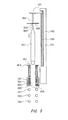
Fig. 5 shows a state in which the glass base material is attached to the glass base material elongating apparatus of the comparative example. -
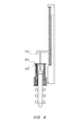
Fig. 6 shows a state in which the hanging shaft tube is lowered. -
Fig. 7 shows a state in which the top lid and the extendable top chamber are connected by the splicing fitting. -
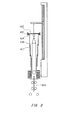
Fig. 8 shows a state in which the cylinder is extended. - Hereinafter, an embodiment of the present invention will be described, but the embodiment does not limit the invention.
Figs. 1 to 4 show an exemplary glass base material elongating apparatus according to the present embodiment. The major portions of the elongating apparatus are the raising/lowering mechanism (reference numerals in the 100s), the glass base material hanging mechanism (reference numerals in the 200s), the heating furnace (reference numerals in the 300s), the extendable top chamber (reference numerals in the 400s), the top chamber lifting mechanism (reference numerals in the 500s), and the pulling mechanism (reference numerals in the 700s). Here, a glass base material workpiece (reference numerals in the 600s) is mounted. - As shown in
Fig. 1 , the raising/lowering mechanism raises and lowers acarriage 104 using aball screw 103 and aguide rail 102 attached to acolumn 101. The hangingshaft 202 and the hangingshaft tube 203 are connected to thecarriage 104 as the glass base material hanging mechanism, and theglass base material 601 is suspended from ahanging shaft tube 203 via adummy rod 602. An XY table 201 is disposed at the top end of the hangingshaft 202, thereby enabling adjustment of the horizontal position of the glass base material. - The heating furnace is arranged below the raising/lowering mechanism, and is formed of a
carbon heater 301, a carbonthermal insulator 302, a water-cooledmain chamber 303, acarbon muffle tube 304 for distancing the glass base material from debris generated by the heater and the thermal insulator, ashutter 305 that can adjust the opening diameter to prevent atmosphere from entering from the outside, and an electrode and inert gas inlet that are not shown. - The extendable top chamber formed of a
multilayer glass cylinder 401 is connected to the top portion of the heating furnace, and aflange 404 is provided on the top portion of the outermost tube of themultilayer glass cylinder 401. A glasscylinder lifting member 503 is attached to the carriage, and a plurality ofsupport columns 502 oriented downward are attached to the outer periphery of the glasscylinder lifting member 503. As shown inFigs. 2 and3 , by connecting thesupport columns 502 and the glasscylinder support member 501 arranged below theflange 404 using a splicing fitting such as a bolt and nut, the bottom surface of theflange 404 can be held up by the glasscylinder support member 501. Each glass cylinder forming the multilayer glass cylinder has anouter claw 406 attached to the top portion thereof and aninner claw 407 attached to the bottom portion thereof. By raising the raising/lowering mechanism, theouter claw 406 moves onto theinner claw 407 such that the cylinder extends, such as shown inFig. 4 . - The
top lid 402 is suspended from the glasscylinder lifting member 503 via a toplid hanging jig 504. The inner diameter of thetop lid 402 is larger than the outer diameter of the hangingshaft 202, to ensure the drive amount in the horizontal direction of thehanging shaft 202. In order to prevent air from entering into and furnace gas from leaking out of the gaps between thetop lid 402 and thehanging shaft 202, agas seal plate 403 having an inner diameter slightly larger than the outer diameter of the hangingshaft 202 is placed on thetop lid 402, thereby realizing drive in the horizontal direction of the glass base material without damaging the gas sealing ability. - As made clear from
Fig. 1 , thetop lid 402 is merely placed on theflange 404, and no securing force other than the weight of thetop lid 402 itself is applied. Therefore, since large forces such as warping of metal portions do not act on thetop lid 402 or theflange 404, damage to thetop lid 402 and theflange 404 can be avoided. Furthermore, by using material with good thermal resistance and shape stability at high temperature, such as quartz glass, for thetop lid 402, oxidation damage of thecarbon muffle tube 304 can be prevented since there are no gaps between thetop lid 402 and theflange 404 even when the temperature is increased. - The pulling mechanism is formed by
guide rollers 701 that can grip and release while freely rotating andupper pulling rollers 702 andlower pulling rollers 703 that can grip and release while rotating according to a motor. As shown inFig. 4 , the bottom end of theglass base material 601 is heated in the heating furnace, and after the pullingdummy 603 has been fused thereto, the pullingdummy 603 or elongated glass rod is pulled down by the pulling mechanism while being lowered by the raising/lowering mechanism, thereby enabling the glass base material to be elongated into a glass rod with a desired outer diameter. - As a comparative example,
Figs. 5 to 8 are used to describe an elongating apparatus that uses an extendable multilayer glass cylinder top chamber.Figs. 5 to 8 show the attachment of theglass base material 601, the combination of the glass base material hanging mechanism and the extendable top chamber, and the fusing of thepulling dummy 603. The major portions of the elongating apparatus are the raising/lowering mechanism (reference numerals in the 100s), the glass base material hanging mechanism (reference numerals in the 200s), the heating furnace (reference numerals in the 300s), the extendable top chamber (reference numerals in the 400s), and the pulling mechanism (reference numerals in the 700s). Here, a glass base material workpiece (reference numerals in the 600s) is mounted. - The raising/lowering mechanism raises and lowers a
carriage 104 using aball screw 103 and aguide rail 102 attached to acolumn 101. The hangingshaft 202 and the hangingshaft tube 203 are connected to thecarriage 104 as the glass base material hanging mechanism, and theglass base material 601 is suspended from ahanging shaft tube 203 via adummy rod 602. - The heating furnace is arranged below the raising/lowering mechanism, and is formed of a
carbon heater 301, a carbonthermal insulator 302, a water-cooledmain chamber 303, acarbon muffle tube 304 for distancing theglass base material 601 from debris generated by theheater 301 and thethermal insulator 302, ashutter 305 that can adjust the opening diameter to prevent atmosphere from entering from the outside, and an electrode and inert gas inlet that are not shown. - The extendable top chamber formed of a
multilayer glass cylinder 401 is connected to the top portion of the heating furnace. Aflange 404 is provided on the top portion of the outermost tube of themultilayer glass cylinder 401, and atop lid 402 is placed on the top of the hanging shaft tube 203 (seeFig. 5 ). When theglass base material 601 is lowered, thetop lid 402 is placed on the flange 404 (Fig. 6 ), and then connected by the splicing fitting 405 (Fig. 7 ). Each glass cylinder forming themultilayer glass cylinder 401 has anouter claw 406 attached to the top portion thereof and aninner claw 407 attached to the bottom portion thereof. By raising the raising/lowering mechanism, theouter claw 406 moves onto theinner claw 407 such that the cylinder extends, such as shown inFig. 8 . - The pulling mechanism is formed by
guide rollers 701 that can grip and release while freely rotating and upper pullingrollers 702 and lower pullingrollers 703 that can grip and release while rotating according to a motor. As shown inFig. 8 , the bottom end of theglass base material 601 is heated in the heating furnace, and after the pullingdummy 603 has been fused thereto, the pullingdummy 603 or elongated glass rod is pulled down by the pulling mechanism while being lowered by the raising/lowering mechanism, thereby enabling theglass base material 601 to be elongated into a glass rod with a desired outer diameter. - As the elongation progresses, the extendable top chamber contracts. When the top chamber is completely contracted, the distance between the
top lid 402 and the heating furnace is small, and thetop lid 402 and the splicing fitting 405 are at a high temperature. Since thetop lid 402 supports the weight of the extendable top chamber, thetop lid 402 is preferably formed using metal instead of a brittle material such as glass or ceramic. However, if such material is used, the top portion becomes warped at high temperatures, and this results in damage from the stress on theflange 404. - Furthermore, if the attachment by the splicing fitting 405 is weak, gaps occur between the
top lid 402 and theflange 404. As a result, the internal gas in the heating furnace that has been lightened by the heating rises upward and escapes, and external atmosphere enters from the bottom of the heating furnace to replace this escaped gas, thereby causing oxidation damage to thecarbon muffle tube 304. - In contrast, the glass base material elongating apparatus according to the present embodiment includes an extendable top chamber formed of a
multilayer glass cylinder 401 that houses the glass base material and a top chamber support mechanism formed of thecylinder support member 501 that supports from below theflange 404 provided on the top of the outermost tube in themultilayer glass cylinder 401 and the glasscylinder lifting member 503 that lifts up the cylinder support member. Therefore, theflange 404 of themultilayer glass cylinder 401 is supported from below without being secured to thetop lid 402. As a result, damage to theflange 404 caused by warping due to heat of a metal portion can be prevented. Furthermore, gaps between thetop lid 402 and theflange 404 can be prevented, and therefore the possibility of thecarbon muffle tube 304 being damaged is prevented. - Furthermore, a material that does not substantially deform due to heat, such as quartz glass, is used for the top lid. As a result, deformation due to heat and the resulting gaps between the
flange 404 and thetop lid 402 can be restricted. - Yet further, the XY table 201 is provided in the glass base material hanging mechanism and the
gas seal plate 403 that is slideable in the XY direction is provided on the top of the top lid. Therefore, the glass base material can be driven horizontally independently of the extendable top chamber, thereby decreasing curvature of the elongated glass rod. In addition, since the glass base material hanging mechanism and top chamber lifting mechanism are attached to asingle carriage 104 instead of the top chamber lifting mechanism being provided independently, the configuration of the apparatus is simplified and the cost of the apparatus can be decreased. - While the embodiment of the present invention has been described, the technical scope of the invention is not limited to the above described embodiment. It is apparent to persons skilled in the art that various alterations and improvements can be added to the above-described embodiment. It is also apparent from the scope of the claims that the embodiments added with such alterations or improvements can be included in the technical scope of the invention.
- 101: column, 102: guide rail, 103: ball screw, 104: carriage, 201: XY table, 202: hanging shaft, 203: hanging shaft tube, 301: heater, 302: thermal insulator, 303: main chamber, 304: carbon muffle tube, 305: shutter, 401: multilayer glass cylinder, 402: top lid, 403: gas seal plate, 404: flange, 405: splicing fitting, 406: outer claw, 407: inner claw, 501: cylinder support member, 502: support column, 503: glass cylinder lifting member, 504: top lid hanging jig, 601: glass base material, 602: dummy rod, 603: pulling dummy, 701: guide roller, 702: upper pulling roller, 703: lower pulling roller
Claims (6)
- A glass base material elongating apparatus comprising:a heating furnace;an extendable top chamber formed of a multilayer cylinder disposed above the heating furnace;a glass base material hanging mechanism that hangs a glass base material into the heating furnace and the extendable top chamber; anda top chamber lifting mechanism, whereina flange is formed on a top portion of an outermost tube of the multilayer cylinder, andthe top chamber lifting mechanism includes a cylinder support member that supports the flange from below and a cylinder lifting member that lifts up the cylinder support member.
- The glass base material elongating apparatus according to Claim 1, wherein a top lid is placed on top of the multilayer cylinder without being secured to the multilayer cylinder.
- The glass base material elongating apparatus according to Claim 1 or 2,
wherein
the multilayer cylinder is made of glass. - The glass base material elongating apparatus according to any one of Claims 1 to 3, wherein
the multilayer cylinder is air-tight. - The glass base material elongating apparatus according to Claim 2, wherein the glass base material hanging mechanism includes an XY table, and
a gas seal plate that is slideable in the XY direction is included on top of the top lid. - The glass base material elongating apparatus according to any one of Claims 1 to 5, wherein
the glass base material hanging mechanism and the top chamber lifting mechanism are attached to a single carriage.
Applications Claiming Priority (1)
| Application Number | Priority Date | Filing Date | Title |
|---|---|---|---|
| JP2012223166A JP5854963B2 (en) | 2012-10-05 | 2012-10-05 | Glass base material drawing equipment |
Publications (2)
| Publication Number | Publication Date |
|---|---|
| EP2716611A1 true EP2716611A1 (en) | 2014-04-09 |
| EP2716611B1 EP2716611B1 (en) | 2016-03-30 |
Family
ID=49301341
Family Applications (1)
| Application Number | Title | Priority Date | Filing Date |
|---|---|---|---|
| EP13186999.2A Not-in-force EP2716611B1 (en) | 2012-10-05 | 2013-10-02 | Apparatus for elongating a glass optical fibre preform |
Country Status (4)
| Country | Link |
|---|---|
| US (1) | US9085482B2 (en) |
| EP (1) | EP2716611B1 (en) |
| JP (1) | JP5854963B2 (en) |
| CN (1) | CN103708718B (en) |
Families Citing this family (4)
| Publication number | Priority date | Publication date | Assignee | Title |
|---|---|---|---|---|
| JP6565556B2 (en) * | 2015-09-30 | 2019-08-28 | 住友電気工業株式会社 | Glass base material lifting device |
| CN107255602B (en) * | 2017-06-06 | 2020-05-05 | 武汉烽火锐拓科技有限公司 | Method and device for on-line measuring density of loose body |
| NL2020854B1 (en) * | 2018-03-22 | 2019-10-02 | Corning Inc | Method and apparatus for suppressing flow instabilities in an optical fiber draw system |
| WO2021150367A1 (en) | 2020-01-24 | 2021-07-29 | Corning Incorporated | Optical fiber draw furnace system and method |
Citations (7)
| Publication number | Priority date | Publication date | Assignee | Title |
|---|---|---|---|---|
| JPH0930827A (en) | 1995-07-17 | 1997-02-04 | Shin Etsu Chem Co Ltd | Manufacturing method of optical fiber preform |
| JPH1160259A (en) | 1997-08-07 | 1999-03-02 | Shin Etsu Chem Co Ltd | Glass base material stretching equipment |
| JP2003183041A (en) * | 2001-12-13 | 2003-07-03 | Shin Etsu Chem Co Ltd | Glass base material stretching apparatus and stretching method |
| JP2005104763A (en) | 2003-09-30 | 2005-04-21 | Shin Etsu Chem Co Ltd | Optical fiber preform drawing method |
| JP2011084409A (en) * | 2009-10-13 | 2011-04-28 | Sumitomo Electric Ind Ltd | Method and apparatus for drawing optical fiber |
| JP2011116592A (en) | 2009-12-03 | 2011-06-16 | Shin-Etsu Chemical Co Ltd | Glass preform drawing apparatus |
| US20120222452A1 (en) * | 2011-03-02 | 2012-09-06 | Shin-Etsu Chemical Co., Ltd. | Elongating method and apparatus for glass base material |
Family Cites Families (3)
| Publication number | Priority date | Publication date | Assignee | Title |
|---|---|---|---|---|
| JPS61281038A (en) * | 1985-06-03 | 1986-12-11 | Ocean Cable Co Ltd | Apparatus for producing optical fiber preform |
| JPH07108784B2 (en) * | 1987-01-19 | 1995-11-22 | 住友電気工業株式会社 | Optical fiber drawing furnace |
| JP5023016B2 (en) * | 2007-08-10 | 2012-09-12 | 信越化学工業株式会社 | Optical fiber manufacturing apparatus and drawing furnace sealing method |
-
2012
- 2012-10-05 JP JP2012223166A patent/JP5854963B2/en active Active
-
2013
- 2013-09-30 CN CN201310462480.9A patent/CN103708718B/en not_active Expired - Fee Related
- 2013-10-01 US US14/042,734 patent/US9085482B2/en active Active
- 2013-10-02 EP EP13186999.2A patent/EP2716611B1/en not_active Not-in-force
Patent Citations (8)
| Publication number | Priority date | Publication date | Assignee | Title |
|---|---|---|---|---|
| JPH0930827A (en) | 1995-07-17 | 1997-02-04 | Shin Etsu Chem Co Ltd | Manufacturing method of optical fiber preform |
| JPH1160259A (en) | 1997-08-07 | 1999-03-02 | Shin Etsu Chem Co Ltd | Glass base material stretching equipment |
| JP2003183041A (en) * | 2001-12-13 | 2003-07-03 | Shin Etsu Chem Co Ltd | Glass base material stretching apparatus and stretching method |
| JP2005104763A (en) | 2003-09-30 | 2005-04-21 | Shin Etsu Chem Co Ltd | Optical fiber preform drawing method |
| JP2011084409A (en) * | 2009-10-13 | 2011-04-28 | Sumitomo Electric Ind Ltd | Method and apparatus for drawing optical fiber |
| JP2011116592A (en) | 2009-12-03 | 2011-06-16 | Shin-Etsu Chemical Co Ltd | Glass preform drawing apparatus |
| EP2336092A1 (en) * | 2009-12-03 | 2011-06-22 | Shin-Etsu Chemical Co., Ltd. | Glass preform drawing apparatus |
| US20120222452A1 (en) * | 2011-03-02 | 2012-09-06 | Shin-Etsu Chemical Co., Ltd. | Elongating method and apparatus for glass base material |
Also Published As
| Publication number | Publication date |
|---|---|
| CN103708718A (en) | 2014-04-09 |
| US20140096566A1 (en) | 2014-04-10 |
| EP2716611B1 (en) | 2016-03-30 |
| JP2014073946A (en) | 2014-04-24 |
| JP5854963B2 (en) | 2016-02-09 |
| US9085482B2 (en) | 2015-07-21 |
| CN103708718B (en) | 2017-07-21 |
Similar Documents
| Publication | Publication Date | Title |
|---|---|---|
| US9085482B2 (en) | Glass base material elongating apparatus | |
| JP6119299B2 (en) | Optical fiber drawing method | |
| US10106451B2 (en) | Glass rod machining method and machining apparatus | |
| CN101429677A (en) | Polycrystalline silicon ingot furnace | |
| CN113735433B (en) | A fusion splicing device for optical fiber manufacturing | |
| JP5556117B2 (en) | Optical fiber drawing method and drawing apparatus | |
| CN115930602A (en) | Bell jar furnace for processing ceramic circuit element | |
| CN111707101A (en) | Melting furnace | |
| JPH06271324A (en) | Production of quartz glass preform | |
| CN110035980B (en) | Sealing structure of optical fiber drawing furnace, and manufacturing method of optical fiber | |
| JP2010095400A (en) | Device for pulling single crystal | |
| CN106064883B (en) | Sintering method and sintering device for porous glass base material | |
| JP6515483B2 (en) | Optical fiber drawing apparatus and optical fiber drawing method | |
| JP6302833B2 (en) | Glass rod drawing method | |
| CN108101355A (en) | A kind of body core stick heat preservation degassing equipment of production capacity extension | |
| JP6303744B2 (en) | Optical fiber manufacturing apparatus and optical fiber manufacturing method | |
| TWI866064B (en) | Crystal growth device and method for determining seeding position | |
| JP2011046563A (en) | Method for drawing optical fiber | |
| JP5040848B2 (en) | Silicon single crystal manufacturing equipment | |
| CN102810949B (en) | Assembling machine for stator and rotator of large-scale and medium-scale motors | |
| JP2017171549A (en) | Optical fiber preform contraction processing method, and processing device | |
| JP2018080372A (en) | Elevating mechanism for heat treatment apparatus, heat treatment apparatus, installation space for heat treatment apparatus, and installation method for heat treatment apparatus | |
| CN118417817B (en) | Bearing installation equipment | |
| JP2010090017A (en) | Apparatus and method for manufacturing optical fiber preform | |
| JP4996760B1 (en) | Batch type heat treatment furnace |
Legal Events
| Date | Code | Title | Description |
|---|---|---|---|
| PUAI | Public reference made under article 153(3) epc to a published international application that has entered the european phase |
Free format text: ORIGINAL CODE: 0009012 |
|
| AK | Designated contracting states |
Kind code of ref document: A1 Designated state(s): AL AT BE BG CH CY CZ DE DK EE ES FI FR GB GR HR HU IE IS IT LI LT LU LV MC MK MT NL NO PL PT RO RS SE SI SK SM TR |
|
| AX | Request for extension of the european patent |
Extension state: BA ME |
|
| 17P | Request for examination filed |
Effective date: 20141009 |
|
| RBV | Designated contracting states (corrected) |
Designated state(s): AL AT BE BG CH CY CZ DE DK EE ES FI FR GB GR HR HU IE IS IT LI LT LU LV MC MK MT NL NO PL PT RO RS SE SI SK SM TR |
|
| GRAP | Despatch of communication of intention to grant a patent |
Free format text: ORIGINAL CODE: EPIDOSNIGR1 |
|
| RIC1 | Information provided on ipc code assigned before grant |
Ipc: C03B 37/012 20060101AFI20151022BHEP |
|
| INTG | Intention to grant announced |
Effective date: 20151117 |
|
| RAP1 | Party data changed (applicant data changed or rights of an application transferred) |
Owner name: SHIN-ETSU CHEMICAL CO., LTD. |
|
| GRAS | Grant fee paid |
Free format text: ORIGINAL CODE: EPIDOSNIGR3 |
|
| GRAA | (expected) grant |
Free format text: ORIGINAL CODE: 0009210 |
|
| AK | Designated contracting states |
Kind code of ref document: B1 Designated state(s): AL AT BE BG CH CY CZ DE DK EE ES FI FR GB GR HR HU IE IS IT LI LT LU LV MC MK MT NL NO PL PT RO RS SE SI SK SM TR |
|
| REG | Reference to a national code |
Ref country code: GB Ref legal event code: FG4D |
|
| REG | Reference to a national code |
Ref country code: CH Ref legal event code: EP |
|
| REG | Reference to a national code |
Ref country code: AT Ref legal event code: REF Ref document number: 785189 Country of ref document: AT Kind code of ref document: T Effective date: 20160415 |
|
| REG | Reference to a national code |
Ref country code: IE Ref legal event code: FG4D |
|
| REG | Reference to a national code |
Ref country code: DE Ref legal event code: R096 Ref document number: 602013005880 Country of ref document: DE |
|
| REG | Reference to a national code |
Ref country code: LT Ref legal event code: MG4D |
|
| PG25 | Lapsed in a contracting state [announced via postgrant information from national office to epo] |
Ref country code: HR Free format text: LAPSE BECAUSE OF FAILURE TO SUBMIT A TRANSLATION OF THE DESCRIPTION OR TO PAY THE FEE WITHIN THE PRESCRIBED TIME-LIMIT Effective date: 20160330 Ref country code: NO Free format text: LAPSE BECAUSE OF FAILURE TO SUBMIT A TRANSLATION OF THE DESCRIPTION OR TO PAY THE FEE WITHIN THE PRESCRIBED TIME-LIMIT Effective date: 20160630 Ref country code: FI Free format text: LAPSE BECAUSE OF FAILURE TO SUBMIT A TRANSLATION OF THE DESCRIPTION OR TO PAY THE FEE WITHIN THE PRESCRIBED TIME-LIMIT Effective date: 20160330 Ref country code: GR Free format text: LAPSE BECAUSE OF FAILURE TO SUBMIT A TRANSLATION OF THE DESCRIPTION OR TO PAY THE FEE WITHIN THE PRESCRIBED TIME-LIMIT Effective date: 20160701 |
|
| REG | Reference to a national code |
Ref country code: NL Ref legal event code: MP Effective date: 20160330 |
|
| REG | Reference to a national code |
Ref country code: AT Ref legal event code: MK05 Ref document number: 785189 Country of ref document: AT Kind code of ref document: T Effective date: 20160330 |
|
| PG25 | Lapsed in a contracting state [announced via postgrant information from national office to epo] |
Ref country code: LT Free format text: LAPSE BECAUSE OF FAILURE TO SUBMIT A TRANSLATION OF THE DESCRIPTION OR TO PAY THE FEE WITHIN THE PRESCRIBED TIME-LIMIT Effective date: 20160330 Ref country code: RS Free format text: LAPSE BECAUSE OF FAILURE TO SUBMIT A TRANSLATION OF THE DESCRIPTION OR TO PAY THE FEE WITHIN THE PRESCRIBED TIME-LIMIT Effective date: 20160330 Ref country code: SE Free format text: LAPSE BECAUSE OF FAILURE TO SUBMIT A TRANSLATION OF THE DESCRIPTION OR TO PAY THE FEE WITHIN THE PRESCRIBED TIME-LIMIT Effective date: 20160330 Ref country code: LV Free format text: LAPSE BECAUSE OF FAILURE TO SUBMIT A TRANSLATION OF THE DESCRIPTION OR TO PAY THE FEE WITHIN THE PRESCRIBED TIME-LIMIT Effective date: 20160330 |
|
| PG25 | Lapsed in a contracting state [announced via postgrant information from national office to epo] |
Ref country code: NL Free format text: LAPSE BECAUSE OF FAILURE TO SUBMIT A TRANSLATION OF THE DESCRIPTION OR TO PAY THE FEE WITHIN THE PRESCRIBED TIME-LIMIT Effective date: 20160330 |
|
| PG25 | Lapsed in a contracting state [announced via postgrant information from national office to epo] |
Ref country code: IS Free format text: LAPSE BECAUSE OF FAILURE TO SUBMIT A TRANSLATION OF THE DESCRIPTION OR TO PAY THE FEE WITHIN THE PRESCRIBED TIME-LIMIT Effective date: 20160730 Ref country code: PL Free format text: LAPSE BECAUSE OF FAILURE TO SUBMIT A TRANSLATION OF THE DESCRIPTION OR TO PAY THE FEE WITHIN THE PRESCRIBED TIME-LIMIT Effective date: 20160330 Ref country code: EE Free format text: LAPSE BECAUSE OF FAILURE TO SUBMIT A TRANSLATION OF THE DESCRIPTION OR TO PAY THE FEE WITHIN THE PRESCRIBED TIME-LIMIT Effective date: 20160330 |
|
| PG25 | Lapsed in a contracting state [announced via postgrant information from national office to epo] |
Ref country code: RO Free format text: LAPSE BECAUSE OF FAILURE TO SUBMIT A TRANSLATION OF THE DESCRIPTION OR TO PAY THE FEE WITHIN THE PRESCRIBED TIME-LIMIT Effective date: 20160330 Ref country code: AT Free format text: LAPSE BECAUSE OF FAILURE TO SUBMIT A TRANSLATION OF THE DESCRIPTION OR TO PAY THE FEE WITHIN THE PRESCRIBED TIME-LIMIT Effective date: 20160330 Ref country code: SK Free format text: LAPSE BECAUSE OF FAILURE TO SUBMIT A TRANSLATION OF THE DESCRIPTION OR TO PAY THE FEE WITHIN THE PRESCRIBED TIME-LIMIT Effective date: 20160330 Ref country code: ES Free format text: LAPSE BECAUSE OF FAILURE TO SUBMIT A TRANSLATION OF THE DESCRIPTION OR TO PAY THE FEE WITHIN THE PRESCRIBED TIME-LIMIT Effective date: 20160330 Ref country code: PT Free format text: LAPSE BECAUSE OF FAILURE TO SUBMIT A TRANSLATION OF THE DESCRIPTION OR TO PAY THE FEE WITHIN THE PRESCRIBED TIME-LIMIT Effective date: 20160801 Ref country code: SM Free format text: LAPSE BECAUSE OF FAILURE TO SUBMIT A TRANSLATION OF THE DESCRIPTION OR TO PAY THE FEE WITHIN THE PRESCRIBED TIME-LIMIT Effective date: 20160330 Ref country code: CZ Free format text: LAPSE BECAUSE OF FAILURE TO SUBMIT A TRANSLATION OF THE DESCRIPTION OR TO PAY THE FEE WITHIN THE PRESCRIBED TIME-LIMIT Effective date: 20160330 |
|
| PG25 | Lapsed in a contracting state [announced via postgrant information from national office to epo] |
Ref country code: IT Free format text: LAPSE BECAUSE OF FAILURE TO SUBMIT A TRANSLATION OF THE DESCRIPTION OR TO PAY THE FEE WITHIN THE PRESCRIBED TIME-LIMIT Effective date: 20160330 Ref country code: BE Free format text: LAPSE BECAUSE OF FAILURE TO SUBMIT A TRANSLATION OF THE DESCRIPTION OR TO PAY THE FEE WITHIN THE PRESCRIBED TIME-LIMIT Effective date: 20160330 |
|
| REG | Reference to a national code |
Ref country code: DE Ref legal event code: R097 Ref document number: 602013005880 Country of ref document: DE |
|
| PG25 | Lapsed in a contracting state [announced via postgrant information from national office to epo] |
Ref country code: DK Free format text: LAPSE BECAUSE OF FAILURE TO SUBMIT A TRANSLATION OF THE DESCRIPTION OR TO PAY THE FEE WITHIN THE PRESCRIBED TIME-LIMIT Effective date: 20160330 |
|
| PLBE | No opposition filed within time limit |
Free format text: ORIGINAL CODE: 0009261 |
|
| STAA | Information on the status of an ep patent application or granted ep patent |
Free format text: STATUS: NO OPPOSITION FILED WITHIN TIME LIMIT |
|
| 26N | No opposition filed |
Effective date: 20170103 |
|
| PG25 | Lapsed in a contracting state [announced via postgrant information from national office to epo] |
Ref country code: SI Free format text: LAPSE BECAUSE OF FAILURE TO SUBMIT A TRANSLATION OF THE DESCRIPTION OR TO PAY THE FEE WITHIN THE PRESCRIBED TIME-LIMIT Effective date: 20160330 |
|
| REG | Reference to a national code |
Ref country code: CH Ref legal event code: PL |
|
| REG | Reference to a national code |
Ref country code: IE Ref legal event code: MM4A |
|
| REG | Reference to a national code |
Ref country code: FR Ref legal event code: ST Effective date: 20170630 |
|
| PG25 | Lapsed in a contracting state [announced via postgrant information from national office to epo] |
Ref country code: FR Free format text: LAPSE BECAUSE OF NON-PAYMENT OF DUE FEES Effective date: 20161102 Ref country code: CH Free format text: LAPSE BECAUSE OF NON-PAYMENT OF DUE FEES Effective date: 20161031 Ref country code: LI Free format text: LAPSE BECAUSE OF NON-PAYMENT OF DUE FEES Effective date: 20161031 |
|
| PG25 | Lapsed in a contracting state [announced via postgrant information from national office to epo] |
Ref country code: LU Free format text: LAPSE BECAUSE OF NON-PAYMENT OF DUE FEES Effective date: 20161002 |
|
| PG25 | Lapsed in a contracting state [announced via postgrant information from national office to epo] |
Ref country code: IE Free format text: LAPSE BECAUSE OF NON-PAYMENT OF DUE FEES Effective date: 20161002 |
|
| PG25 | Lapsed in a contracting state [announced via postgrant information from national office to epo] |
Ref country code: HU Free format text: LAPSE BECAUSE OF FAILURE TO SUBMIT A TRANSLATION OF THE DESCRIPTION OR TO PAY THE FEE WITHIN THE PRESCRIBED TIME-LIMIT; INVALID AB INITIO Effective date: 20131002 Ref country code: CY Free format text: LAPSE BECAUSE OF FAILURE TO SUBMIT A TRANSLATION OF THE DESCRIPTION OR TO PAY THE FEE WITHIN THE PRESCRIBED TIME-LIMIT Effective date: 20160330 |
|
| GBPC | Gb: european patent ceased through non-payment of renewal fee |
Effective date: 20171002 |
|
| PG25 | Lapsed in a contracting state [announced via postgrant information from national office to epo] |
Ref country code: MC Free format text: LAPSE BECAUSE OF FAILURE TO SUBMIT A TRANSLATION OF THE DESCRIPTION OR TO PAY THE FEE WITHIN THE PRESCRIBED TIME-LIMIT Effective date: 20160330 Ref country code: MT Free format text: LAPSE BECAUSE OF NON-PAYMENT OF DUE FEES Effective date: 20161031 Ref country code: MK Free format text: LAPSE BECAUSE OF FAILURE TO SUBMIT A TRANSLATION OF THE DESCRIPTION OR TO PAY THE FEE WITHIN THE PRESCRIBED TIME-LIMIT Effective date: 20160330 |
|
| PG25 | Lapsed in a contracting state [announced via postgrant information from national office to epo] |
Ref country code: BG Free format text: LAPSE BECAUSE OF FAILURE TO SUBMIT A TRANSLATION OF THE DESCRIPTION OR TO PAY THE FEE WITHIN THE PRESCRIBED TIME-LIMIT Effective date: 20160330 Ref country code: GB Free format text: LAPSE BECAUSE OF NON-PAYMENT OF DUE FEES Effective date: 20171002 |
|
| PG25 | Lapsed in a contracting state [announced via postgrant information from national office to epo] |
Ref country code: AL Free format text: LAPSE BECAUSE OF FAILURE TO SUBMIT A TRANSLATION OF THE DESCRIPTION OR TO PAY THE FEE WITHIN THE PRESCRIBED TIME-LIMIT Effective date: 20160330 Ref country code: TR Free format text: LAPSE BECAUSE OF FAILURE TO SUBMIT A TRANSLATION OF THE DESCRIPTION OR TO PAY THE FEE WITHIN THE PRESCRIBED TIME-LIMIT Effective date: 20160330 |
|
| PGFP | Annual fee paid to national office [announced via postgrant information from national office to epo] |
Ref country code: DE Payment date: 20230830 Year of fee payment: 11 |
|
| REG | Reference to a national code |
Ref country code: DE Ref legal event code: R119 Ref document number: 602013005880 Country of ref document: DE |
|
| PG25 | Lapsed in a contracting state [announced via postgrant information from national office to epo] |
Ref country code: DE Free format text: LAPSE BECAUSE OF NON-PAYMENT OF DUE FEES Effective date: 20250501 |