EP2716606A2 - Underwater capillary tube plasma device having gas channel - Google Patents
Underwater capillary tube plasma device having gas channel Download PDFInfo
- Publication number
- EP2716606A2 EP2716606A2 EP12792771.3A EP12792771A EP2716606A2 EP 2716606 A2 EP2716606 A2 EP 2716606A2 EP 12792771 A EP12792771 A EP 12792771A EP 2716606 A2 EP2716606 A2 EP 2716606A2
- Authority
- EP
- European Patent Office
- Prior art keywords
- supply unit
- plasma device
- gas supply
- gas
- fluid
- Prior art date
- Legal status (The legal status is an assumption and is not a legal conclusion. Google has not performed a legal analysis and makes no representation as to the accuracy of the status listed.)
- Granted
Links
Images




Classifications
-
- C—CHEMISTRY; METALLURGY
- C02—TREATMENT OF WATER, WASTE WATER, SEWAGE, OR SLUDGE
- C02F—TREATMENT OF WATER, WASTE WATER, SEWAGE, OR SLUDGE
- C02F1/00—Treatment of water, waste water, or sewage
- C02F1/46—Treatment of water, waste water, or sewage by electrochemical methods
- C02F1/461—Treatment of water, waste water, or sewage by electrochemical methods by electrolysis
- C02F1/467—Treatment of water, waste water, or sewage by electrochemical methods by electrolysis by electrochemical disinfection; by electrooxydation or by electroreduction
-
- C—CHEMISTRY; METALLURGY
- C02—TREATMENT OF WATER, WASTE WATER, SEWAGE, OR SLUDGE
- C02F—TREATMENT OF WATER, WASTE WATER, SEWAGE, OR SLUDGE
- C02F1/00—Treatment of water, waste water, or sewage
- C02F1/46—Treatment of water, waste water, or sewage by electrochemical methods
- C02F1/4608—Treatment of water, waste water, or sewage by electrochemical methods using electrical discharges
-
- H—ELECTRICITY
- H05—ELECTRIC TECHNIQUES NOT OTHERWISE PROVIDED FOR
- H05H—PLASMA TECHNIQUE; PRODUCTION OF ACCELERATED ELECTRICALLY-CHARGED PARTICLES OR OF NEUTRONS; PRODUCTION OR ACCELERATION OF NEUTRAL MOLECULAR OR ATOMIC BEAMS
- H05H1/00—Generating plasma; Handling plasma
- H05H1/24—Generating plasma
- H05H1/48—Generating plasma using an arc
- H05H1/486—Arrangements to provide capillary discharges
-
- C—CHEMISTRY; METALLURGY
- C02—TREATMENT OF WATER, WASTE WATER, SEWAGE, OR SLUDGE
- C02F—TREATMENT OF WATER, WASTE WATER, SEWAGE, OR SLUDGE
- C02F1/00—Treatment of water, waste water, or sewage
- C02F1/46—Treatment of water, waste water, or sewage by electrochemical methods
-
- C—CHEMISTRY; METALLURGY
- C02—TREATMENT OF WATER, WASTE WATER, SEWAGE, OR SLUDGE
- C02F—TREATMENT OF WATER, WASTE WATER, SEWAGE, OR SLUDGE
- C02F1/00—Treatment of water, waste water, or sewage
- C02F1/72—Treatment of water, waste water, or sewage by oxidation
-
- H—ELECTRICITY
- H05—ELECTRIC TECHNIQUES NOT OTHERWISE PROVIDED FOR
- H05H—PLASMA TECHNIQUE; PRODUCTION OF ACCELERATED ELECTRICALLY-CHARGED PARTICLES OR OF NEUTRONS; PRODUCTION OR ACCELERATION OF NEUTRAL MOLECULAR OR ATOMIC BEAMS
- H05H1/00—Generating plasma; Handling plasma
- H05H1/24—Generating plasma
- H05H1/47—Generating plasma using corona discharges
- H05H1/471—Pointed electrodes
-
- C—CHEMISTRY; METALLURGY
- C02—TREATMENT OF WATER, WASTE WATER, SEWAGE, OR SLUDGE
- C02F—TREATMENT OF WATER, WASTE WATER, SEWAGE, OR SLUDGE
- C02F2303/00—Specific treatment goals
- C02F2303/04—Disinfection
-
- C—CHEMISTRY; METALLURGY
- C02—TREATMENT OF WATER, WASTE WATER, SEWAGE, OR SLUDGE
- C02F—TREATMENT OF WATER, WASTE WATER, SEWAGE, OR SLUDGE
- C02F2305/00—Use of specific compounds during water treatment
- C02F2305/02—Specific form of oxidant
-
- H—ELECTRICITY
- H05—ELECTRIC TECHNIQUES NOT OTHERWISE PROVIDED FOR
- H05H—PLASMA TECHNIQUE; PRODUCTION OF ACCELERATED ELECTRICALLY-CHARGED PARTICLES OR OF NEUTRONS; PRODUCTION OR ACCELERATION OF NEUTRAL MOLECULAR OR ATOMIC BEAMS
- H05H2245/00—Applications of plasma devices
- H05H2245/30—Medical applications
- H05H2245/36—Sterilisation of objects, liquids, volumes or surfaces
Definitions
- the present invention relates to an underwater capillary plasma device, and more particularly, to the technology for effectively purifying polluted water by equipping an underwater capillary plasma discharge electrode with a gas channel.
- these methods include a method using ozone, a method of adding a chemical such as hypochlorous acid (HClO) to polluted water, a method using ultraviolet rays, a method using heat treatment, and the like.
- a chemical such as hypochlorous acid (HClO)
- the present invention is designed to solve the problems of the prior art, and it is an object of the present invention to provide an underwater capillary plasma device having a gas channel capable of purifying polluted water stably and effectively using underwater capillary plasma discharge.
- an underwater capillary plasma device including a power supply unit configured to supply a power source, a discharge electrode configured to receive the power source supplied from the power supply unit and induce capillary plasma discharge inside a fluid, and a gas supply unit configured to inject an auxiliary gas into the discharge electrode.
- the underwater capillary plasma discharge electrode is equipped with a gas channel, plasma species can be generated from water decomposition caused by plasma discharge, and various chemical reactive species can be generated according to the injected auxiliary gas, thereby effectively removing underwater pollutants.
- the reactive species generated by the plasma discharge can be increased in concentration and lifetime in the fluid so that a purification effect using plasma can be maximized.
- the auxiliary gas is supplied as described above, plasma can be generated even by a smaller supply of power, compared with when the auxiliary gas is not injected, thereby reducing energy consumption for purification of the fluid.
- FIG. 1 a block diagram illustrating an underwater capillary plasma device 100 according to one exemplary embodiment of the present invention.
- the underwater capillary plasma device 100 includes a power supply unit 102, a discharge electrode 104, and a gas supply unit 106.
- the power supply unit 102 serves to receive a power source (for example a common alternating current (AC) power source), convert the power source into a direct current (DC) or AC power source having a voltage with a predetermined size, and output the DC or AC power source.
- a power source for example a common alternating current (AC) power source
- DC direct current
- the power supply unit 102 of the present invention may also be used in a circuit configured to output the AC power source.
- the power supply unit 102 may be configured to include a transformer 108 and a rectifier 110, both of which are configured to amplify the voltage of the input power source.
- the power supply unit 102 may be configured to have a proper shape according to the kind and voltage of the power source to be input, and the kind of the power source to be output, and the like.
- the discharge electrode 104 serves to purify a fluid 112 such as polluted water by receiving the power source supplied from the power supply unit 102, and inducing capillary plasma discharge 114 inside the polluted fluid 112.
- Plasma generated by such capillary plasma discharge decomposes water molecules in the fluid 112 to generate reactive species such as OH-, O, H, H 2 O 2 , HO 2 , HClO, Cl 2 , HCl, and the like.
- the generated reactive species serve to remove pollutants (i.e., volatile organic compounds, microorganisms, algae, etc.) in the fluid.
- the gas supply unit 106 serves to inject an auxiliary gas into the fluid 112 in which capillary plasma discharge takes place by means of the discharge electrode 104.
- an auxiliary gas may include ozone (O 3 ), oxygen (O 2 ), nitrogen (N 2 ), argon (Ar), helium (He), air, and a mixture thereof.
- hydrogen peroxide (H 2 O 2 ) in a liquid phase may also be used in the gas supply unit 106.
- the auxiliary gas injected thus is supplied into the plasma generated in the discharge electrode 104, thereby aiding in generating the plasma and purifying the fluid 112 using the plasma.
- the reactive species in the fluid 112 may be increased in concentration and lifetime in the fluid, compared with when the auxiliary gas is not injected. Therefore, a purification effect of the fluid 112 by the plasma may be maximized.
- the plasma may be generated even by a smaller supply of power, compared with when the auxiliary gas is not injected, thereby reducing energy consumption for purification of the fluid.
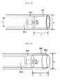
- FIG. 2 is a diagram showing a first exemplary embodiment of a discharge electrode 104 and a gas supply unit 106 of the underwater capillary plasma device 100 according to the present invention.
- the discharge electrode 104 is configured to include a metal tip 200, and a dielectric tube 202.
- the metal tip 200 is electrically connected to an output terminal of the power supply unit 102, and may be formed of a metal material, for example, at least one selected from the group consisting of tungsten, molybdenum, titanium, and stainless steel (SUS). Such a material forming the metal tip 200 may be determined in consideration of the shape and size of the metal tip 200, the processability or cost of the metal material, and the like.
- the metal tip 200 may be formed of stainless steel having good processability, and an end portion of the metal tip 200 in which the plasma is generated may be formed of tungsten having high wear resistance.
- the dielectric tube 202 is formed in a cylindrical shape to surround the metal tip 200, and protrudes from an end of the metal tip 200 by a certain length (d). That is, an end portion of the metal tip 200 is formed so that the end portion can be recessed inwards from the dielectric tube 202 by the length (d).
- the length (d) may be properly determined in consideration of fine foams generated inside the dielectric tube 202, and a discharge effect taking place in the fine foams, and thus may be in a range of approximately 2 mm to 4 mm.
- Such a dielectric tube 202 may be, for example, formed of alumina or quartz.
- the dielectric tube 202 may be formed with a diameter (a) of approximately 2 mm to 4 mm.
- the gas supply unit 106 includes a gas supply pipe 204 configured to supply an auxiliary gas into a fluid.
- the gas supply pipe 204 is formed through the metal tip 200 in a longitudinal direction, and thus is configured to directly supply the auxiliary gas into the plasma generated at the end portion of the metal tip 200.
- the gas supply pipe 204 may be formed with a diameter (b) of approximately 0.7 mm to 1.2 mm.
- FIG. 3 is a diagram showing a second exemplary embodiment of the discharge electrode 104 and the gas supply unit 106 of the underwater capillary plasma device 100 according to the present invention.
- this exemplary embodiment is also configured to include a metal tip 300, a dielectric tube 302, and a gas supply pipe 304.
- the shape of the gas supply pipe 304 is different from that of the gas supply pipe 204.
- an end portion of the gas supply pipe 304 which contacts with the fluid is tapered in diameter. That is, in FIG. 3 , the relationship of c > b (wherein c represents an inner diameter of the gas supply pipe 304, and b represents a diameter of a gas outlet portion of the gas supply pipe 304) is established.
- the flow rate of the auxiliary gas may increase at the corresponding portion, which makes it possible to supply the auxiliary gas into the plasma more smoothly.
- FIG. 4 is a diagram showing a third exemplary embodiment of the discharge electrode 104 and the gas supply unit 106 of the underwater capillary plasma device 100 according to the present invention.
- this exemplary embodiment is also configured to include a metal tip 400, a dielectric tube 402, and a gas supply pipe 404.
- the shape of the dielectric tube 402 is different from those of the dielectric tubes 202 and 302, compared with the first and second exemplary embodiments. That is, in this case of this exemplary embodiment, an end 406 of the dielectric tube 402 coming in contact with the fluid is formed so that the end 406 of the dielectric tube 402 can be sloped in a direction spanning from an inner circumferential surface to an outer circumferential surface of a cylinder constituting the dielectric tube 402.
- the wear of the dielectric tube 402 by the plasma may be reduced.
- the gas supply pipe 404 is shown in FIG. 4 so that the shape of the gas supply pipe 404 can be identical to that of the gas supply pipe 204 according to the second exemplary embodiment.
- this is merely one example for the purpose of illustration, a gas supply pipe having the shape as shown in FIG. 2 may be also used herein.
- FIG. 5 is a diagram showing a fourth exemplary embodiment of the discharge electrode 104 and the gas supply unit 106 of the underwater capillary plasma device 100 according to the present invention.
- the gas supply pipe 404 is not formed through the inside of a metal tip 500, but formed in a cylindrical shape to surround the dielectric tube 502.
- an auxiliary gas is not directly injected into the plasma generated at an end portion of the metal tip 500, but is supplied in such a manner that the auxiliary gas surrounds the plasma.
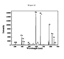
- FIGS. 6 to 10 are diagrams illustrating the effects of the underwater capillary plasma device 100 according to the present invention.
- FIG. 6 is a diagram showing the concentration of reactive species generated inside a fluid when a gas is supplied into the gas supply unit 106
- FIG. 7 is a diagram showing the concentration of reactive species generated inside a fluid when nitrogen (N 2 ) gas is supplied into the gas supply unit 106
- FIG. 8 is a diagram showing the concentration of reactive species generated inside a fluid when air is supplied into the gas supply unit 106.
- FIGS. 6 to 8 it could be seen that the concentrations of O and OH increase when nitrogen or air is supplied into the gas supply unit 106.
- FIG. 9 is a graph illustrating the comparison of the Cl contents in the fluid when various kinds of gases are injected into the gas supply unit 106.
- O 2 _O 3 represents the Cl content in the fluid when ozone gas generated from oxygen is injected
- Air_O 3 represents the Cl content in the fluid when ozone gas generated from air is injected.
- the total content of Cl serving as a disinfectant increases when a gas such as (non-gas) oxygen, nitrogen, air, or ozone is injected, compared with when the gas is not injected.
- FIG. 10 is a graph illustrating the results obtained by comparing the cell numbers of E. coli according to the gases supplied into the gas supply unit 106. As shown in FIG. 10 , it could be seen that the cell number of E. coli in the fluid does not decrease when the gas is not supplied (w/o gas), whereas the cell number of E. coli in the fluid suddenly decreases starting from a point of time after the lapse of approximately 15 seconds when nitrogen or ozone is supplied at a rate of 50 sccm or 50 sccm, respectively.
- the underwater capillary plasma device having a gas channel according to the present invention can be widely used for purification of ballast water, sterilization of water used in medical instruments, dishes, humidifiers, and the like, and other applications such as waste water disposal.
Landscapes
- Engineering & Computer Science (AREA)
- Plasma & Fusion (AREA)
- Physics & Mathematics (AREA)
- Chemical & Material Sciences (AREA)
- Hydrology & Water Resources (AREA)
- Life Sciences & Earth Sciences (AREA)
- Spectroscopy & Molecular Physics (AREA)
- Environmental & Geological Engineering (AREA)
- Water Supply & Treatment (AREA)
- Organic Chemistry (AREA)
- Chemical Kinetics & Catalysis (AREA)
- Electrochemistry (AREA)
- General Chemical & Material Sciences (AREA)
- Plasma Technology (AREA)
- Physical Or Chemical Processes And Apparatus (AREA)
Abstract
Description
- This application claims priority to and the benefit of Republic of Korea Patent Application No.
10-2011-0052089, filed on May 31, 2011 - The present invention relates to an underwater capillary plasma device, and more particularly, to the technology for effectively purifying polluted water by equipping an underwater capillary plasma discharge electrode with a gas channel.
- In recent years, research on various methods has been conducted for purification of polluted water and removal of bacteria. For example, these methods include a method using ozone, a method of adding a chemical such as hypochlorous acid (HClO) to polluted water, a method using ultraviolet rays, a method using heat treatment, and the like.
- However, such methods have problems in that the sufficient purification performance of the methods cannot be obtained, the excessive costs may be required to dispose polluted water, or the unexpected side effects may be caused. Therefore, there is an increasing demand for methods of efficiently purifying polluted water and removing microorganisms such as bacteria.
- Accordingly, the present invention is designed to solve the problems of the prior art, and it is an object of the present invention to provide an underwater capillary plasma device having a gas channel capable of purifying polluted water stably and effectively using underwater capillary plasma discharge.
- According to an aspect of the present invention, there is provided an underwater capillary plasma device including a power supply unit configured to supply a power source, a discharge electrode configured to receive the power source supplied from the power supply unit and induce capillary plasma discharge inside a fluid, and a gas supply unit configured to inject an auxiliary gas into the discharge electrode.
- According to exemplary embodiments of the present invention, since the underwater capillary plasma discharge electrode is equipped with a gas channel, plasma species can be generated from water decomposition caused by plasma discharge, and various chemical reactive species can be generated according to the injected auxiliary gas, thereby effectively removing underwater pollutants. Also, when a gas is injected as described herein, the reactive species generated by the plasma discharge can be increased in concentration and lifetime in the fluid so that a purification effect using plasma can be maximized. Further, when the auxiliary gas is supplied as described above, plasma can be generated even by a smaller supply of power, compared with when the auxiliary gas is not injected, thereby reducing energy consumption for purification of the fluid.
-
-
FIG. 1 is a block diagram illustrating an underwatercapillary plasma device 100 according to one exemplary embodiment of the present invention. -
FIG. 2 is a diagram showing a first exemplary embodiment of adischarge electrode 104 and agas supply unit 106 of the underwatercapillary plasma device 100 according to the present invention. -
FIG. 3 is a diagram showing a second exemplary embodiment of thedischarge electrode 104 and thegas supply unit 106 of the underwatercapillary plasma device 100 according to the present invention. -
FIG. 4 is a diagram showing a third exemplary embodiment of thedischarge electrode 104 and thegas supply unit 106 of the underwatercapillary plasma device 100 according to the present invention. -
FIG. 5 is a diagram showing a fourth exemplary embodiment of thedischarge electrode 104 and thegas supply unit 106 of the underwatercapillary plasma device 100 according to the present invention. -
FIG. 6 is a diagram showing the concentration of reactive species generated inside a fluid when a gas is supplied into thegas supply unit 106. -
FIG. 7 is a diagram showing the concentration of reactive species generated inside a fluid when nitrogen (N2) gas is supplied into thegas supply unit 106. -
FIG. 8 is a diagram showing the concentration of reactive species generated inside a fluid when air is supplied into thegas supply unit 106. -
FIG. 9 is a graph illustrating the comparison of the total Cl contents in the fluid when various kinds of gases are injected into thegas supply unit 106. -
FIG. 10 is a graph illustrating the results obtained by comparing the cell numbers of E. coli according to the gases supplied into thegas supply unit 106. - Hereinafter, preferred exemplary embodiment of the present invention will be described in further detail with reference to the accompanying drawings. However, the description proposed herein is just a preferable example for the purpose of illustrations only, not intended to limit the scope of the invention.
- For the purpose of describing particular embodiments of the present invention, when detailed description of the prior art related to the present invention is considered to make the gist of the present invention
- In describing the present invention, detailed descriptions with respect to known functions or constructions of the present invention will be omitted when the detailed descriptions are considered to make the gist of the present invention unclear. In addition, the terminology used herein is defined in consideration of the functions or constructions in the present invention, and may be altered according to the users' or operators' intentions and practice. Accordingly, the definitions of these terms therefore may be determined based on the contents throughout the specification.
- Thus, the scope of this invention should be determined by the appended claims and their legal equivalents. Therefore, it will be appreciated that the scope of the present invention fully encompasses other embodiments which may become obvious to those skilled in the art to which the present invention belongs.
-
FIG. 1 a block diagram illustrating an underwatercapillary plasma device 100 according to one exemplary embodiment of the present invention. - As shown in
FIG. 1 , the underwatercapillary plasma device 100 according to one exemplary embodiment of the present invention includes apower supply unit 102, adischarge electrode 104, and agas supply unit 106. - The
power supply unit 102 serves to receive a power source (for example a common alternating current (AC) power source), convert the power source into a direct current (DC) or AC power source having a voltage with a predetermined size, and output the DC or AC power source. Although one exemplary embodiment of a circuit configured to convert an externally input power source into a DC power source having a predetermined voltage is shown in this exemplary embodiment as shown inFIG. 1 , thepower supply unit 102 of the present invention may also be used in a circuit configured to output the AC power source. In this exemplary embodiment, thepower supply unit 102 may be configured to include atransformer 108 and arectifier 110, both of which are configured to amplify the voltage of the input power source. However, this is merely one example for the purpose of illustration, thepower supply unit 102 may be configured to have a proper shape according to the kind and voltage of the power source to be input, and the kind of the power source to be output, and the like. - The
discharge electrode 104 serves to purify afluid 112 such as polluted water by receiving the power source supplied from thepower supply unit 102, and inducingcapillary plasma discharge 114 inside the pollutedfluid 112. Plasma generated by such capillary plasma discharge decomposes water molecules in thefluid 112 to generate reactive species such as OH-, O, H, H2O2, HO2, HClO, Cl2, HCl, and the like. In this case, the generated reactive species serve to remove pollutants (i.e., volatile organic compounds, microorganisms, algae, etc.) in the fluid. - The
gas supply unit 106 serves to inject an auxiliary gas into thefluid 112 in which capillary plasma discharge takes place by means of thedischarge electrode 104. Examples of such an auxiliary gas may include ozone (O3), oxygen (O2), nitrogen (N2), argon (Ar), helium (He), air, and a mixture thereof. Here, hydrogen peroxide (H2O2) in a liquid phase may also be used in thegas supply unit 106. The auxiliary gas injected thus is supplied into the plasma generated in thedischarge electrode 104, thereby aiding in generating the plasma and purifying thefluid 112 using the plasma. That is, when the auxiliary gas is injected as described above, the reactive species in thefluid 112 may be increased in concentration and lifetime in the fluid, compared with when the auxiliary gas is not injected. Therefore, a purification effect of thefluid 112 by the plasma may be maximized. In addition, when the auxiliary gas is supplied as described above, the plasma may be generated even by a smaller supply of power, compared with when the auxiliary gas is not injected, thereby reducing energy consumption for purification of the fluid. -
FIG. 2 is a diagram showing a first exemplary embodiment of adischarge electrode 104 and agas supply unit 106 of the underwatercapillary plasma device 100 according to the present invention. - As shown in
FIG. 2 , thedischarge electrode 104 is configured to include ametal tip 200, and adielectric tube 202. - The
metal tip 200 is electrically connected to an output terminal of thepower supply unit 102, and may be formed of a metal material, for example, at least one selected from the group consisting of tungsten, molybdenum, titanium, and stainless steel (SUS). Such a material forming themetal tip 200 may be determined in consideration of the shape and size of themetal tip 200, the processability or cost of the metal material, and the like. For example, themetal tip 200 may be formed of stainless steel having good processability, and an end portion of themetal tip 200 in which the plasma is generated may be formed of tungsten having high wear resistance. - The
dielectric tube 202 is formed in a cylindrical shape to surround themetal tip 200, and protrudes from an end of themetal tip 200 by a certain length (d). That is, an end portion of themetal tip 200 is formed so that the end portion can be recessed inwards from thedielectric tube 202 by the length (d). The length (d) may be properly determined in consideration of fine foams generated inside thedielectric tube 202, and a discharge effect taking place in the fine foams, and thus may be in a range of approximately 2 mm to 4 mm. Such adielectric tube 202 may be, for example, formed of alumina or quartz. Thedielectric tube 202 may be formed with a diameter (a) of approximately 2 mm to 4 mm. - Meanwhile, according to the present invention, the
gas supply unit 106 includes agas supply pipe 204 configured to supply an auxiliary gas into a fluid. According to this exemplary embodiment, thegas supply pipe 204 is formed through themetal tip 200 in a longitudinal direction, and thus is configured to directly supply the auxiliary gas into the plasma generated at the end portion of themetal tip 200. Thegas supply pipe 204 may be formed with a diameter (b) of approximately 0.7 mm to 1.2 mm. -
FIG. 3 is a diagram showing a second exemplary embodiment of thedischarge electrode 104 and thegas supply unit 106 of the underwatercapillary plasma device 100 according to the present invention. - Like in the first exemplary embodiment, this exemplary embodiment is also configured to include a
metal tip 300, adielectric tube 302, and agas supply pipe 304. As shown inFIG. 3 , compared with the first exemplary embodiment, the shape of thegas supply pipe 304 is different from that of thegas supply pipe 204. In this exemplary embodiment, an end portion of thegas supply pipe 304 which contacts with the fluid is tapered in diameter. That is, inFIG. 3 , the relationship of c > b (wherein c represents an inner diameter of thegas supply pipe 304, and b represents a diameter of a gas outlet portion of the gas supply pipe 304) is established. As described above, when the end portion of thegas supply pipe 304 can be tapered in diameter, the flow rate of the auxiliary gas may increase at the corresponding portion, which makes it possible to supply the auxiliary gas into the plasma more smoothly. -
FIG. 4 is a diagram showing a third exemplary embodiment of thedischarge electrode 104 and thegas supply unit 106 of the underwatercapillary plasma device 100 according to the present invention. - Like in the first and second exemplary embodiments, this exemplary embodiment is also configured to include a
metal tip 400, adielectric tube 402, and agas supply pipe 404. However, the shape of thedielectric tube 402 is different from those of thedielectric tubes end 406 of thedielectric tube 402 coming in contact with the fluid is formed so that theend 406 of thedielectric tube 402 can be sloped in a direction spanning from an inner circumferential surface to an outer circumferential surface of a cylinder constituting thedielectric tube 402. When an inclined plane is formed at an end portion of thedielectric tube 402 as described above, the wear of thedielectric tube 402 by the plasma may be reduced. Meanwhile, thegas supply pipe 404 is shown inFIG. 4 so that the shape of thegas supply pipe 404 can be identical to that of thegas supply pipe 204 according to the second exemplary embodiment. However, this is merely one example for the purpose of illustration, a gas supply pipe having the shape as shown inFIG. 2 may be also used herein. -
FIG. 5 is a diagram showing a fourth exemplary embodiment of thedischarge electrode 104 and thegas supply unit 106 of the underwatercapillary plasma device 100 according to the present invention. - According to this exemplary embodiment, the
gas supply pipe 404 is not formed through the inside of ametal tip 500, but formed in a cylindrical shape to surround thedielectric tube 502. When thegas supply pipe 404 is formed as described above, an auxiliary gas is not directly injected into the plasma generated at an end portion of themetal tip 500, but is supplied in such a manner that the auxiliary gas surrounds the plasma. -
FIGS. 6 to 10 are diagrams illustrating the effects of the underwatercapillary plasma device 100 according to the present invention. - First,
FIG. 6 is a diagram showing the concentration of reactive species generated inside a fluid when a gas is supplied into thegas supply unit 106,FIG. 7 is a diagram showing the concentration of reactive species generated inside a fluid when nitrogen (N2) gas is supplied into thegas supply unit 106, andFIG. 8 is a diagram showing the concentration of reactive species generated inside a fluid when air is supplied into thegas supply unit 106. As shown inFIGS. 6 to 8 , it could be seen that the concentrations of O and OH increase when nitrogen or air is supplied into thegas supply unit 106. -
FIG. 9 is a graph illustrating the comparison of the Cl contents in the fluid when various kinds of gases are injected into thegas supply unit 106. InFIG. 9 , O2_O3 represents the Cl content in the fluid when ozone gas generated from oxygen is injected, and Air_O3 represents the Cl content in the fluid when ozone gas generated from air is injected. As shown inFIG. 9 , it could be seen that the total content of Cl serving as a disinfectant increases when a gas such as (non-gas) oxygen, nitrogen, air, or ozone is injected, compared with when the gas is not injected. -
FIG. 10 is a graph illustrating the results obtained by comparing the cell numbers of E. coli according to the gases supplied into thegas supply unit 106. As shown inFIG. 10 , it could be seen that the cell number of E. coli in the fluid does not decrease when the gas is not supplied (w/o gas), whereas the cell number of E. coli in the fluid suddenly decreases starting from a point of time after the lapse of approximately 15 seconds when nitrogen or ozone is supplied at a rate of 50 sccm or 50 sccm, respectively. - As described above, the underwater capillary plasma device having a gas channel according to the present invention can be widely used for purification of ballast water, sterilization of water used in medical instruments, dishes, humidifiers, and the like, and other applications such as waste water disposal.
- Although the present invention has been described above in further detail with reference to the ideal exemplary embodiments, it should be understood by those skilled in the related art to which the present invention pertains that various changes and modifications will be made to the above-described exemplary embodiments without departing from the scope of the present invention.
- Thus, it is intended that the present invention covers all such modifications provided they come within the scope of the appended claims and their equivalents.
-
- 100: underwater capillary plasma device
- 102: power supply unit
- 104: discharge electrode
- 106: gas supply unit
- 200, 300, 400: metal tip
- 202, 302, 402: dielectric tubes
- 204, 304, 404: gas supply pipes
Claims (10)
- An underwater capillary plasma device comprising:a power supply unit configured to supply a power source;a discharge electrode configured to receive the power source supplied from the power supply unit and induce capillary plasma discharge inside a fluid; anda gas supply unit configured to inject an auxiliary gas into the discharge electrode.
- The underwater capillary plasma device of claim 1, wherein the discharge electrode comprises:a metal tip electrically connected to an output terminal of the power supply unit; anda cylindrically shaped dielectric tube to surround the metal tip and protrude from an end of the metal tip by a certain length.
- The underwater capillary plasma device of claim 2, wherein the metal tip is formed of at least one material selected from the group consisting of tungsten, molybdenum, titanium, and stainless steel (SUS).
- The underwater capillary plasma device of claim 2, wherein the dielectric tube is formed of at least one material selected from the group consisting of alumina, and quartz.
- The underwater capillary plasma device of claim 2, wherein the dielectric tube is formed so that an end of the dielectric tube coming in contact with the fluid is sloped in a direction spanning from an inner circumferential surface to an outer circumferential surface of the cylinder.
- The underwater capillary plasma device of claim 2, wherein the gas supply unit comprises a gas supply pipe formed through the metal tip.
- The underwater capillary plasma device of claim 6, wherein the gas supply pipe is formed so that an end portion of the metal tip coming in contact with the fluid is tapered in diameter.
- The underwater capillary plasma device of claim 2, wherein the gas supply unit comprises a cylindrical gas supply pipe formed to surround the dielectric tube.
- The underwater capillary plasma device of claim 1, wherein the gas supply unit supplies a gas including at least one selected from the group consisting of ozone (O3), oxygen (O2), nitrogen (N2), argon (Ar), helium (He), and air into the fluid.
- The underwater capillary plasma device of claim 1, wherein the gas supply unit is configured to inject hydrogen peroxide in a liquid phase into the fluid.
Applications Claiming Priority (2)
| Application Number | Priority Date | Filing Date | Title |
|---|---|---|---|
| KR1020110052089A KR101266157B1 (en) | 2011-05-31 | 2011-05-31 | Submersible capillary plasma apparatus with gas channel |
| PCT/KR2012/004073 WO2012165799A2 (en) | 2011-05-31 | 2012-05-23 | Underwater capillary tube plasma device having gas channel |
Publications (3)
| Publication Number | Publication Date |
|---|---|
| EP2716606A2 true EP2716606A2 (en) | 2014-04-09 |
| EP2716606A4 EP2716606A4 (en) | 2014-11-05 |
| EP2716606B1 EP2716606B1 (en) | 2019-12-04 |
Family
ID=47260028
Family Applications (1)
| Application Number | Title | Priority Date | Filing Date |
|---|---|---|---|
| EP12792771.3A Active EP2716606B1 (en) | 2011-05-31 | 2012-05-23 | Underwater capillary plasma device |
Country Status (5)
| Country | Link |
|---|---|
| EP (1) | EP2716606B1 (en) |
| KR (1) | KR101266157B1 (en) |
| CN (1) | CN103635434B (en) |
| ES (1) | ES2765052T3 (en) |
| WO (1) | WO2012165799A2 (en) |
Families Citing this family (20)
| Publication number | Priority date | Publication date | Assignee | Title |
|---|---|---|---|---|
| KR101428525B1 (en) * | 2012-12-27 | 2014-08-11 | 한국기초과학지원연구원 | Underwater seed plasma treatment method |
| KR101575693B1 (en) * | 2014-01-29 | 2015-12-21 | 한국기초과학지원연구원 | Device for plasma water treatment |
| CN105883966A (en) * | 2014-12-24 | 2016-08-24 | 苏州超等环保科技有限公司 | Efficient plasma load for water treatment |
| CN105884063A (en) * | 2015-06-04 | 2016-08-24 | 庞浩辉 | Waste water regeneration purified water system device |
| CN105565447B (en) * | 2015-11-06 | 2018-05-08 | 济宁普悦环保科技有限公司 | Energy-saving sterilizing pond |
| KR101709644B1 (en) * | 2015-12-21 | 2017-02-23 | 에스케이건설 주식회사 | Water Treating Apparatus for generating hydrogen peroxide |
| CN106007046B (en) * | 2016-05-10 | 2019-06-11 | 上海电力学院 | A kind of desulfurization wastewater hardness ion resource pretreatment process |
| CN105948300B (en) * | 2016-07-26 | 2019-01-11 | 上海能洲环保科技有限公司 | Energy storage instantaneously heated type safety hot-drink making machine |
| US10822255B2 (en) | 2017-07-14 | 2020-11-03 | Doosan Heavy Industries & Construction Co., Ld | Water treatment apparatus using underwater plasma discharge and water treatment system including same |
| KR101953691B1 (en) | 2018-05-29 | 2019-03-04 | 이석 | Underwater dielectic barrier discharge plasma generating device |
| KR101984437B1 (en) | 2018-12-26 | 2019-05-30 | 김숙 | Water treating apparatus using plasma |
| CN109761304B (en) * | 2019-03-05 | 2024-07-02 | 成都科衡环保技术有限公司 | Microwave plasma generation module for water treatment, reactor and application thereof |
| KR102219915B1 (en) * | 2019-04-10 | 2021-02-23 | 부산대학교 산학협력단 | Method for preparing sulfonized solid acid catalyst using gas-liquid interface plasma process |
| KR102106879B1 (en) * | 2019-06-07 | 2020-05-07 | 한국기초과학지원연구원 | Plasma generating device and water purification system equipped therewith |
| CN110418484B (en) * | 2019-08-30 | 2020-11-06 | 西安交通大学 | An air jet discharge generating device |
| CN111405739B (en) * | 2020-03-06 | 2021-05-18 | 大连理工大学 | A uniform discharge micro-plasma generator in an atmospheric pressure capillary |
| KR102479272B1 (en) * | 2020-03-26 | 2022-12-20 | 한국핵융합에너지연구원 | Disinfection system using plasma discharge water and spray nozzle spraying plasma discharge water as droplet |
| KR102458891B1 (en) * | 2020-10-19 | 2022-10-24 | 가톨릭대학교 산학협력단 | Endoscope channel sterilize device |
| CN114513890A (en) * | 2022-04-19 | 2022-05-17 | 北京大学第三医院(北京大学第三临床医学院) | Plasma sterilization device with high energy utilization rate and application |
| KR20250116422A (en) * | 2024-01-25 | 2025-08-01 | 한국기계연구원 | Plasma water treatment apparatus and waste water purifying system using plasma, and waste water purifying method using plasma |
Family Cites Families (8)
| Publication number | Priority date | Publication date | Assignee | Title |
|---|---|---|---|---|
| US5464513A (en) * | 1994-01-11 | 1995-11-07 | Scientific Utilization, Inc. | Method and apparatus for water decontamination using electrical discharge |
| JP2000260396A (en) * | 1999-03-05 | 2000-09-22 | Quark Systems Co Ltd | Excimer lamp, excimer irradiation device, and organic compond decomposition method |
| US20050189278A1 (en) * | 2004-02-03 | 2005-09-01 | Takanori Iijima | Apparatus for decomposing organic matter with radical treatment method using electric discharge |
| ES2362928T3 (en) * | 2005-10-25 | 2011-07-15 | Aseptix Technologies B.V | ACTIVATED PEROXIDE SOLUTIONS AND PROCESS FOR PREPARATION. |
| WO2009036579A1 (en) * | 2007-09-21 | 2009-03-26 | Hoffmann Neopac Ag | Apparatus for plasma supported coating of the inner surface of tube-like packaging containers made of plastics with the assistance of a non-thermal reactive ambient pressure beam plasma |
| KR100967878B1 (en) * | 2007-11-27 | 2010-07-05 | 주식회사 에스디알앤디 | Underwater Plasma Generator and Method |
| KR20090110060A (en) * | 2008-04-17 | 2009-10-21 | 주식회사 에스디알앤디 | Underwater Plasma Generator and Method |
| KR100924649B1 (en) * | 2009-05-22 | 2009-11-02 | 정장근 | Generation device and method of high density underwater plasma torch |
-
2011
- 2011-05-31 KR KR1020110052089A patent/KR101266157B1/en active Active
-
2012
- 2012-05-23 ES ES12792771T patent/ES2765052T3/en active Active
- 2012-05-23 WO PCT/KR2012/004073 patent/WO2012165799A2/en not_active Ceased
- 2012-05-23 CN CN201280026758.1A patent/CN103635434B/en active Active
- 2012-05-23 EP EP12792771.3A patent/EP2716606B1/en active Active
Also Published As
| Publication number | Publication date |
|---|---|
| EP2716606A4 (en) | 2014-11-05 |
| KR101266157B1 (en) | 2013-05-21 |
| EP2716606B1 (en) | 2019-12-04 |
| WO2012165799A2 (en) | 2012-12-06 |
| ES2765052T3 (en) | 2020-06-05 |
| CN103635434A (en) | 2014-03-12 |
| CN103635434B (en) | 2016-01-20 |
| WO2012165799A3 (en) | 2013-02-21 |
| KR20120133454A (en) | 2012-12-11 |
Similar Documents
| Publication | Publication Date | Title |
|---|---|---|
| EP2716606B1 (en) | Underwater capillary plasma device | |
| KR101256577B1 (en) | Electrode for underwater discharge and apparatus for generating underwater capillary plasma including the electrode | |
| JP4041224B2 (en) | Liquid processing method and liquid processing apparatus | |
| CN101734763B (en) | Method for processing drinking water and device using same | |
| KR101211823B1 (en) | Apparatus of waste water disposal using plasma and bubble | |
| US20090071910A1 (en) | Liquid treatment apparatus and liquid treatment method | |
| KR101579349B1 (en) | Water treatment apparatus using plasma-membrane and method using the same | |
| KR101918147B1 (en) | Plasma Water Treatment Apparatus | |
| KR100895122B1 (en) | Method and device for reducing waste activated sludge and improving anaerobic digestion efficiency | |
| KR100924649B1 (en) | Generation device and method of high density underwater plasma torch | |
| JP2010137212A (en) | Apparatus for generating plasma | |
| JP2012217917A (en) | Water treatment apparatus | |
| Ma et al. | Effects of a porous dielectric in atmospheric-pressure plasma jets submerged in water | |
| Kuwahara | Reduction in energy consumption using fuel cells in nonthermal plasma-based water sterilization by bubbling ozone | |
| KR100902138B1 (en) | Wastewater Purification System Using Ozone | |
| CN201620057U (en) | A drinking water treatment device | |
| JP6178522B2 (en) | Wastewater purification system using high voltage discharge and fine bubbles | |
| CN106145476A (en) | The innoxious device of Cement Composite Treated by Plasma water and Cement Composite Treated by Plasma water detoxification method | |
| KR101808768B1 (en) | Plasma electrode and apparatus for generating underwater capillary plasma with the electrode | |
| Al-Jobouri et al. | Design an ozone generator by using dielectric barrier discharge | |
| KR20130119131A (en) | Apparatus for sterilization using potocatalyst and high voltage pulse and sterilization method | |
| KR101575693B1 (en) | Device for plasma water treatment | |
| WO1991011395A1 (en) | Oxidizing apparatus | |
| CN2353743Y (en) | Waste-water treatment apparatus | |
| CN104150559A (en) | Method for purifying aquaculture water by using micro-plasma |
Legal Events
| Date | Code | Title | Description |
|---|---|---|---|
| PUAI | Public reference made under article 153(3) epc to a published international application that has entered the european phase |
Free format text: ORIGINAL CODE: 0009012 |
|
| 17P | Request for examination filed |
Effective date: 20131129 |
|
| AK | Designated contracting states |
Kind code of ref document: A2 Designated state(s): AL AT BE BG CH CY CZ DE DK EE ES FI FR GB GR HR HU IE IS IT LI LT LU LV MC MK MT NL NO PL PT RO RS SE SI SK SM TR |
|
| DAX | Request for extension of the european patent (deleted) | ||
| A4 | Supplementary search report drawn up and despatched |
Effective date: 20141006 |
|
| RIC1 | Information provided on ipc code assigned before grant |
Ipc: C02F 1/46 20060101ALI20140929BHEP Ipc: C02F 1/467 20060101AFI20140929BHEP Ipc: H05H 1/46 20060101ALI20140929BHEP Ipc: H05H 1/48 20060101ALI20140929BHEP Ipc: H05H 1/24 20060101ALI20140929BHEP Ipc: C02F 1/72 20060101ALI20140929BHEP |
|
| GRAP | Despatch of communication of intention to grant a patent |
Free format text: ORIGINAL CODE: EPIDOSNIGR1 |
|
| STAA | Information on the status of an ep patent application or granted ep patent |
Free format text: STATUS: GRANT OF PATENT IS INTENDED |
|
| INTG | Intention to grant announced |
Effective date: 20190628 |
|
| GRAS | Grant fee paid |
Free format text: ORIGINAL CODE: EPIDOSNIGR3 |
|
| GRAA | (expected) grant |
Free format text: ORIGINAL CODE: 0009210 |
|
| STAA | Information on the status of an ep patent application or granted ep patent |
Free format text: STATUS: THE PATENT HAS BEEN GRANTED |
|
| AK | Designated contracting states |
Kind code of ref document: B1 Designated state(s): AL AT BE BG CH CY CZ DE DK EE ES FI FR GB GR HR HU IE IS IT LI LT LU LV MC MK MT NL NO PL PT RO RS SE SI SK SM TR |
|
| REG | Reference to a national code |
Ref country code: GB Ref legal event code: FG4D |
|
| REG | Reference to a national code |
Ref country code: CH Ref legal event code: EP |
|
| REG | Reference to a national code |
Ref country code: AT Ref legal event code: REF Ref document number: 1209179 Country of ref document: AT Kind code of ref document: T Effective date: 20191215 |
|
| REG | Reference to a national code |
Ref country code: IE Ref legal event code: FG4D |
|
| REG | Reference to a national code |
Ref country code: DE Ref legal event code: R096 Ref document number: 602012066236 Country of ref document: DE |
|
| REG | Reference to a national code |
Ref country code: NL Ref legal event code: FP |
|
| REG | Reference to a national code |
Ref country code: LT Ref legal event code: MG4D |
|
| PG25 | Lapsed in a contracting state [announced via postgrant information from national office to epo] |
Ref country code: FI Free format text: LAPSE BECAUSE OF FAILURE TO SUBMIT A TRANSLATION OF THE DESCRIPTION OR TO PAY THE FEE WITHIN THE PRESCRIBED TIME-LIMIT Effective date: 20191204 Ref country code: BG Free format text: LAPSE BECAUSE OF FAILURE TO SUBMIT A TRANSLATION OF THE DESCRIPTION OR TO PAY THE FEE WITHIN THE PRESCRIBED TIME-LIMIT Effective date: 20200304 Ref country code: SE Free format text: LAPSE BECAUSE OF FAILURE TO SUBMIT A TRANSLATION OF THE DESCRIPTION OR TO PAY THE FEE WITHIN THE PRESCRIBED TIME-LIMIT Effective date: 20191204 Ref country code: LV Free format text: LAPSE BECAUSE OF FAILURE TO SUBMIT A TRANSLATION OF THE DESCRIPTION OR TO PAY THE FEE WITHIN THE PRESCRIBED TIME-LIMIT Effective date: 20191204 Ref country code: GR Free format text: LAPSE BECAUSE OF FAILURE TO SUBMIT A TRANSLATION OF THE DESCRIPTION OR TO PAY THE FEE WITHIN THE PRESCRIBED TIME-LIMIT Effective date: 20200305 Ref country code: NO Free format text: LAPSE BECAUSE OF FAILURE TO SUBMIT A TRANSLATION OF THE DESCRIPTION OR TO PAY THE FEE WITHIN THE PRESCRIBED TIME-LIMIT Effective date: 20200304 Ref country code: LT Free format text: LAPSE BECAUSE OF FAILURE TO SUBMIT A TRANSLATION OF THE DESCRIPTION OR TO PAY THE FEE WITHIN THE PRESCRIBED TIME-LIMIT Effective date: 20191204 |
|
| PG25 | Lapsed in a contracting state [announced via postgrant information from national office to epo] |
Ref country code: HR Free format text: LAPSE BECAUSE OF FAILURE TO SUBMIT A TRANSLATION OF THE DESCRIPTION OR TO PAY THE FEE WITHIN THE PRESCRIBED TIME-LIMIT Effective date: 20191204 Ref country code: RS Free format text: LAPSE BECAUSE OF FAILURE TO SUBMIT A TRANSLATION OF THE DESCRIPTION OR TO PAY THE FEE WITHIN THE PRESCRIBED TIME-LIMIT Effective date: 20191204 |
|
| REG | Reference to a national code |
Ref country code: ES Ref legal event code: FG2A Ref document number: 2765052 Country of ref document: ES Kind code of ref document: T3 Effective date: 20200605 |
|
| PG25 | Lapsed in a contracting state [announced via postgrant information from national office to epo] |
Ref country code: AL Free format text: LAPSE BECAUSE OF FAILURE TO SUBMIT A TRANSLATION OF THE DESCRIPTION OR TO PAY THE FEE WITHIN THE PRESCRIBED TIME-LIMIT Effective date: 20191204 |
|
| PG25 | Lapsed in a contracting state [announced via postgrant information from national office to epo] |
Ref country code: EE Free format text: LAPSE BECAUSE OF FAILURE TO SUBMIT A TRANSLATION OF THE DESCRIPTION OR TO PAY THE FEE WITHIN THE PRESCRIBED TIME-LIMIT Effective date: 20191204 Ref country code: CZ Free format text: LAPSE BECAUSE OF FAILURE TO SUBMIT A TRANSLATION OF THE DESCRIPTION OR TO PAY THE FEE WITHIN THE PRESCRIBED TIME-LIMIT Effective date: 20191204 Ref country code: RO Free format text: LAPSE BECAUSE OF FAILURE TO SUBMIT A TRANSLATION OF THE DESCRIPTION OR TO PAY THE FEE WITHIN THE PRESCRIBED TIME-LIMIT Effective date: 20191204 Ref country code: PT Free format text: LAPSE BECAUSE OF FAILURE TO SUBMIT A TRANSLATION OF THE DESCRIPTION OR TO PAY THE FEE WITHIN THE PRESCRIBED TIME-LIMIT Effective date: 20200429 |
|
| PG25 | Lapsed in a contracting state [announced via postgrant information from national office to epo] |
Ref country code: SM Free format text: LAPSE BECAUSE OF FAILURE TO SUBMIT A TRANSLATION OF THE DESCRIPTION OR TO PAY THE FEE WITHIN THE PRESCRIBED TIME-LIMIT Effective date: 20191204 Ref country code: IS Free format text: LAPSE BECAUSE OF FAILURE TO SUBMIT A TRANSLATION OF THE DESCRIPTION OR TO PAY THE FEE WITHIN THE PRESCRIBED TIME-LIMIT Effective date: 20200404 Ref country code: SK Free format text: LAPSE BECAUSE OF FAILURE TO SUBMIT A TRANSLATION OF THE DESCRIPTION OR TO PAY THE FEE WITHIN THE PRESCRIBED TIME-LIMIT Effective date: 20191204 |
|
| REG | Reference to a national code |
Ref country code: DE Ref legal event code: R097 Ref document number: 602012066236 Country of ref document: DE |
|
| REG | Reference to a national code |
Ref country code: AT Ref legal event code: MK05 Ref document number: 1209179 Country of ref document: AT Kind code of ref document: T Effective date: 20191204 |
|
| PLBE | No opposition filed within time limit |
Free format text: ORIGINAL CODE: 0009261 |
|
| STAA | Information on the status of an ep patent application or granted ep patent |
Free format text: STATUS: NO OPPOSITION FILED WITHIN TIME LIMIT |
|
| PG25 | Lapsed in a contracting state [announced via postgrant information from national office to epo] |
Ref country code: DK Free format text: LAPSE BECAUSE OF FAILURE TO SUBMIT A TRANSLATION OF THE DESCRIPTION OR TO PAY THE FEE WITHIN THE PRESCRIBED TIME-LIMIT Effective date: 20191204 |
|
| 26N | No opposition filed |
Effective date: 20200907 |
|
| PG25 | Lapsed in a contracting state [announced via postgrant information from national office to epo] |
Ref country code: AT Free format text: LAPSE BECAUSE OF FAILURE TO SUBMIT A TRANSLATION OF THE DESCRIPTION OR TO PAY THE FEE WITHIN THE PRESCRIBED TIME-LIMIT Effective date: 20191204 Ref country code: SI Free format text: LAPSE BECAUSE OF FAILURE TO SUBMIT A TRANSLATION OF THE DESCRIPTION OR TO PAY THE FEE WITHIN THE PRESCRIBED TIME-LIMIT Effective date: 20191204 Ref country code: PL Free format text: LAPSE BECAUSE OF FAILURE TO SUBMIT A TRANSLATION OF THE DESCRIPTION OR TO PAY THE FEE WITHIN THE PRESCRIBED TIME-LIMIT Effective date: 20191204 |
|
| REG | Reference to a national code |
Ref country code: DE Ref legal event code: R119 Ref document number: 602012066236 Country of ref document: DE |
|
| PG25 | Lapsed in a contracting state [announced via postgrant information from national office to epo] |
Ref country code: LI Free format text: LAPSE BECAUSE OF NON-PAYMENT OF DUE FEES Effective date: 20200531 Ref country code: IT Free format text: LAPSE BECAUSE OF FAILURE TO SUBMIT A TRANSLATION OF THE DESCRIPTION OR TO PAY THE FEE WITHIN THE PRESCRIBED TIME-LIMIT Effective date: 20191204 Ref country code: CH Free format text: LAPSE BECAUSE OF NON-PAYMENT OF DUE FEES Effective date: 20200531 Ref country code: MC Free format text: LAPSE BECAUSE OF FAILURE TO SUBMIT A TRANSLATION OF THE DESCRIPTION OR TO PAY THE FEE WITHIN THE PRESCRIBED TIME-LIMIT Effective date: 20191204 |
|
| REG | Reference to a national code |
Ref country code: BE Ref legal event code: MM Effective date: 20200531 |
|
| GBPC | Gb: european patent ceased through non-payment of renewal fee |
Effective date: 20200523 |
|
| PG25 | Lapsed in a contracting state [announced via postgrant information from national office to epo] |
Ref country code: LU Free format text: LAPSE BECAUSE OF NON-PAYMENT OF DUE FEES Effective date: 20200523 |
|
| REG | Reference to a national code |
Ref country code: ES Ref legal event code: PC2A Owner name: KOREA INSTITUTE OF FUSION ENERGY Effective date: 20210326 |
|
| REG | Reference to a national code |
Ref country code: NL Ref legal event code: PD Owner name: KOREA INSTITUTE OF FUSION ENERGY; KO Free format text: DETAILS ASSIGNMENT: CHANGE OF OWNER(S), ASSIGNMENT; FORMER OWNER NAME: KOREA BASIC SCIENCE INSTITUTE Effective date: 20210323 |
|
| PG25 | Lapsed in a contracting state [announced via postgrant information from national office to epo] |
Ref country code: FR Free format text: LAPSE BECAUSE OF NON-PAYMENT OF DUE FEES Effective date: 20200531 Ref country code: GB Free format text: LAPSE BECAUSE OF NON-PAYMENT OF DUE FEES Effective date: 20200523 Ref country code: IE Free format text: LAPSE BECAUSE OF NON-PAYMENT OF DUE FEES Effective date: 20200523 |
|
| PG25 | Lapsed in a contracting state [announced via postgrant information from national office to epo] |
Ref country code: BE Free format text: LAPSE BECAUSE OF NON-PAYMENT OF DUE FEES Effective date: 20200531 Ref country code: DE Free format text: LAPSE BECAUSE OF NON-PAYMENT OF DUE FEES Effective date: 20201201 |
|
| PG25 | Lapsed in a contracting state [announced via postgrant information from national office to epo] |
Ref country code: TR Free format text: LAPSE BECAUSE OF FAILURE TO SUBMIT A TRANSLATION OF THE DESCRIPTION OR TO PAY THE FEE WITHIN THE PRESCRIBED TIME-LIMIT Effective date: 20191204 Ref country code: MT Free format text: LAPSE BECAUSE OF FAILURE TO SUBMIT A TRANSLATION OF THE DESCRIPTION OR TO PAY THE FEE WITHIN THE PRESCRIBED TIME-LIMIT Effective date: 20191204 Ref country code: CY Free format text: LAPSE BECAUSE OF FAILURE TO SUBMIT A TRANSLATION OF THE DESCRIPTION OR TO PAY THE FEE WITHIN THE PRESCRIBED TIME-LIMIT Effective date: 20191204 |
|
| PG25 | Lapsed in a contracting state [announced via postgrant information from national office to epo] |
Ref country code: MK Free format text: LAPSE BECAUSE OF FAILURE TO SUBMIT A TRANSLATION OF THE DESCRIPTION OR TO PAY THE FEE WITHIN THE PRESCRIBED TIME-LIMIT Effective date: 20191204 |
|
| PGFP | Annual fee paid to national office [announced via postgrant information from national office to epo] |
Ref country code: ES Payment date: 20250613 Year of fee payment: 14 |
|
| PGFP | Annual fee paid to national office [announced via postgrant information from national office to epo] |
Ref country code: NL Payment date: 20260324 Year of fee payment: 15 |