EP2716601A1 - Copper foil for manufacturing graphene and graphene manufacturing method - Google Patents
Copper foil for manufacturing graphene and graphene manufacturing method Download PDFInfo
- Publication number
- EP2716601A1 EP2716601A1 EP12793061.8A EP12793061A EP2716601A1 EP 2716601 A1 EP2716601 A1 EP 2716601A1 EP 12793061 A EP12793061 A EP 12793061A EP 2716601 A1 EP2716601 A1 EP 2716601A1
- Authority
- EP
- European Patent Office
- Prior art keywords
- copper foil
- graphene
- copper
- producing graphene
- less
- Prior art date
- Legal status (The legal status is an assumption and is not a legal conclusion. Google has not performed a legal analysis and makes no representation as to the accuracy of the status listed.)
- Granted
Links
Images


Classifications
-
- C—CHEMISTRY; METALLURGY
- C01—INORGANIC CHEMISTRY
- C01B—NON-METALLIC ELEMENTS; COMPOUNDS THEREOF; METALLOIDS OR COMPOUNDS THEREOF NOT COVERED BY SUBCLASS C01C
- C01B32/00—Carbon; Compounds thereof
- C01B32/15—Nano-sized carbon materials
- C01B32/182—Graphene
- C01B32/184—Preparation
- C01B32/186—Preparation by chemical vapour deposition [CVD]
-
- C—CHEMISTRY; METALLURGY
- C01—INORGANIC CHEMISTRY
- C01B—NON-METALLIC ELEMENTS; COMPOUNDS THEREOF; METALLOIDS OR COMPOUNDS THEREOF NOT COVERED BY SUBCLASS C01C
- C01B32/00—Carbon; Compounds thereof
- C01B32/15—Nano-sized carbon materials
- C01B32/182—Graphene
- C01B32/184—Preparation
-
- B—PERFORMING OPERATIONS; TRANSPORTING
- B01—PHYSICAL OR CHEMICAL PROCESSES OR APPARATUS IN GENERAL
- B01J—CHEMICAL OR PHYSICAL PROCESSES, e.g. CATALYSIS OR COLLOID CHEMISTRY; THEIR RELEVANT APPARATUS
- B01J23/00—Catalysts comprising metals or metal oxides or hydroxides, not provided for in group B01J21/00
- B01J23/70—Catalysts comprising metals or metal oxides or hydroxides, not provided for in group B01J21/00 of the iron group metals or copper
- B01J23/72—Copper
-
- B—PERFORMING OPERATIONS; TRANSPORTING
- B82—NANOTECHNOLOGY
- B82Y—SPECIFIC USES OR APPLICATIONS OF NANOSTRUCTURES; MEASUREMENT OR ANALYSIS OF NANOSTRUCTURES; MANUFACTURE OR TREATMENT OF NANOSTRUCTURES
- B82Y30/00—Nanotechnology for materials or surface science, e.g. nanocomposites
-
- B—PERFORMING OPERATIONS; TRANSPORTING
- B82—NANOTECHNOLOGY
- B82Y—SPECIFIC USES OR APPLICATIONS OF NANOSTRUCTURES; MEASUREMENT OR ANALYSIS OF NANOSTRUCTURES; MANUFACTURE OR TREATMENT OF NANOSTRUCTURES
- B82Y40/00—Manufacture or treatment of nanostructures
-
- C—CHEMISTRY; METALLURGY
- C22—METALLURGY; FERROUS OR NON-FERROUS ALLOYS; TREATMENT OF ALLOYS OR NON-FERROUS METALS
- C22C—ALLOYS
- C22C9/00—Alloys based on copper
-
- C—CHEMISTRY; METALLURGY
- C22—METALLURGY; FERROUS OR NON-FERROUS ALLOYS; TREATMENT OF ALLOYS OR NON-FERROUS METALS
- C22C—ALLOYS
- C22C9/00—Alloys based on copper
- C22C9/02—Alloys based on copper with tin as the next major constituent
-
- C—CHEMISTRY; METALLURGY
- C22—METALLURGY; FERROUS OR NON-FERROUS ALLOYS; TREATMENT OF ALLOYS OR NON-FERROUS METALS
- C22F—CHANGING THE PHYSICAL STRUCTURE OF NON-FERROUS METALS AND NON-FERROUS ALLOYS
- C22F1/00—Changing the physical structure of non-ferrous metals or alloys by heat treatment or by hot or cold working
- C22F1/08—Changing the physical structure of non-ferrous metals or alloys by heat treatment or by hot or cold working of copper or alloys based thereon
-
- B—PERFORMING OPERATIONS; TRANSPORTING
- B01—PHYSICAL OR CHEMICAL PROCESSES OR APPARATUS IN GENERAL
- B01J—CHEMICAL OR PHYSICAL PROCESSES, e.g. CATALYSIS OR COLLOID CHEMISTRY; THEIR RELEVANT APPARATUS
- B01J27/00—Catalysts comprising the elements or compounds of halogens, sulfur, selenium, tellurium, phosphorus or nitrogen; Catalysts comprising carbon compounds
- B01J27/02—Sulfur, selenium or tellurium; Compounds thereof
- B01J27/04—Sulfides
-
- B—PERFORMING OPERATIONS; TRANSPORTING
- B01—PHYSICAL OR CHEMICAL PROCESSES OR APPARATUS IN GENERAL
- B01J—CHEMICAL OR PHYSICAL PROCESSES, e.g. CATALYSIS OR COLLOID CHEMISTRY; THEIR RELEVANT APPARATUS
- B01J37/00—Processes, in general, for preparing catalysts; Processes, in general, for activation of catalysts
- B01J37/0009—Use of binding agents; Moulding; Pressing; Powdering; Granulating; Addition of materials ameliorating the mechanical properties of the product catalyst
-
- B—PERFORMING OPERATIONS; TRANSPORTING
- B01—PHYSICAL OR CHEMICAL PROCESSES OR APPARATUS IN GENERAL
- B01J—CHEMICAL OR PHYSICAL PROCESSES, e.g. CATALYSIS OR COLLOID CHEMISTRY; THEIR RELEVANT APPARATUS
- B01J37/00—Processes, in general, for preparing catalysts; Processes, in general, for activation of catalysts
- B01J37/0081—Preparation by melting
-
- B—PERFORMING OPERATIONS; TRANSPORTING
- B01—PHYSICAL OR CHEMICAL PROCESSES OR APPARATUS IN GENERAL
- B01J—CHEMICAL OR PHYSICAL PROCESSES, e.g. CATALYSIS OR COLLOID CHEMISTRY; THEIR RELEVANT APPARATUS
- B01J37/00—Processes, in general, for preparing catalysts; Processes, in general, for activation of catalysts
- B01J37/16—Reducing
- B01J37/18—Reducing with gases containing free hydrogen
-
- Y—GENERAL TAGGING OF NEW TECHNOLOGICAL DEVELOPMENTS; GENERAL TAGGING OF CROSS-SECTIONAL TECHNOLOGIES SPANNING OVER SEVERAL SECTIONS OF THE IPC; TECHNICAL SUBJECTS COVERED BY FORMER USPC CROSS-REFERENCE ART COLLECTIONS [XRACs] AND DIGESTS
- Y10—TECHNICAL SUBJECTS COVERED BY FORMER USPC
- Y10T—TECHNICAL SUBJECTS COVERED BY FORMER US CLASSIFICATION
- Y10T428/00—Stock material or miscellaneous articles
- Y10T428/12—All metal or with adjacent metals
- Y10T428/12431—Foil or filament smaller than 6 mils
Definitions
- the present invention relates to a copper foil for producing graphene, and a method of producing graphene using the same.
- Graphite has a layered structure where a plurality of layers of carbon six-membered rings planarly arranged is laminated.
- the graphite having a mono atomic layer or around several atomic layers is called as graphene or a graphene sheet.
- the graphene sheet has own electrical, optical and mechanical properties, and in particularly has a high carrier mobility speed. Therefore, the graphene sheet has expected to be applied in various industries as a fuel cell separator, a transparent electrode, a conductive thin film for a display device, a "mercury-free" fluorescent lamp, a composite material, a carrier for Drug Delivery System (DDS) etc.
- DDS Drug Delivery System
- a technology has been developed that a sheet-like monocrystal graphitized metal catalyst is contacted with a carboneous substance and then is heat treated to grow the graphene sheet (Chemical Vapor Deposition (CVD) method) (Patent Literature 1).
- CVD Chemical Vapor Deposition
- the monocrystal graphitized metal catalyst there is described a metal substrate made of Ni, Cu or W, for example.
- Non-Patent Literature 1 a technology has been reported that a graphene film is formed by the chemical vapor deposition method on a copper layer formed on an Ni or Cu metal foil or an Si substrate.
- the graphene film is formed at about 1000°C (Non-Patent Literature 1).
- Patent Literature 1 Japanese Unexamined Patent Publication (Kokai) 2009-143799
- Non-Patent Literature 1 SCIENCE Vol. 324 (2009) P1312-1314
- Non-Patent Document 1 describes that Cu is used as the substrate. Graphene is not grown on a copper foil in a plane direction within a short time. A Cu layer formed on an Si substrate is annealed to provide coarse grains, thereby providing a substrate. In this case, a size of graphene is limited to the size of the Si substrate, and its production costs are high, too.
- the reason for superiority of the copper as the catalyst of graphene growth is that the copper little dissolves carbon.
- carbon atoms produced by thermal decomposition of a hydrocarbon gas form graphene on the surface of the copper.
- the copper no longer acts as the catalyst.
- the hydrocarbon gas will not be further thermally decomposed, and a plurality of graphene layers is unlikely formed. Instead, a graphene monolayer is provided.
- a copper monocrystal is good as a substrate for producing graphene.
- the copper monocrystal is expensive and has a limited size, it is not suitable to form a large area graphene film.
- the copper foil can easily provide the large area.
- the present inventor produced graphene using the copper foil as the substrate, it was found that a sheet resistance of graphene increased to degrade a quality.
- an object of the present invention is to provide a copper foil for producing graphene being capable of producing graphene having a large area with low costs, and a method of producing graphene using the same.
- a first aspect of the present invention provides a copper foil for producing graphene, including oxides and sulfides each having a diameter of 0.5 ⁇ m or more having a total number of 15/mm 2 or less measured by using a scanning electronic microscope before heating at 1000 °C for 1 hour in an atmosphere containing 20 % by volume or more of hydrogen and balance argon.
- a second aspect of the present invention provides a copper foil for producing graphene, including oxides and sulfides each having a diameter of 0.5 ⁇ m or more having a total number of 100/mm 2 or less measured for an area having a total area of 3 mm 2 within a depth of 10 ⁇ m from a surface that is a cross-section in parallel to the rolling direction by using a scanning electronic microscope before heating at 1000 °C for 1 hour in an atmosphere containing 20 % by volume or more of hydrogen and balance argon.
- a purity of Cu is 99.95 to 99.995% by mass.
- the copper foil for producing graphene of the present invention consists of tough pitch copper in accordance with JIS-H3100; or consists of oxygen free copper in accordance with JIS-H3100, or contains 0.050 % by mass or less of one or more of elements selected from the group consisting of Sn and Ag to the tough pitch copper or the oxygen free copper.
- the present invention provides a method of producing grapheme using the copper foil for producing graphene, comprising the steps of: providing a carbon-containing gas while placing the heated copper foil to form graphene on a surface of the copper foil for producing graphene; laminating a transfer sheet on the surface of the graphene, and etching and removing the copper foil for producing graphene while transferring the graphene to the transfer sheet.
- a copper foil being capable of producing graphene having a large area with low costs.
- a copper foil includes an oxide and a sulfide each having a diameter of 0.5 ⁇ m or more having a total number of 15/mm 2 or less measured by using a scanning electronic microscope before heating at 1000 °C for 1 hour in an atmosphere containing 20 % by volume or more of hydrogen and balance argon.
- the present inventor sought the cause of the increase in the sheet resistance of graphene and the poor quality when graphene is produced using the copper foil as the substrate, and found that the copper foil is uneven, thereby inhibiting the growth of graphene.
- each carbon atom bond in graphene is in the order of nm, but a surface irregularity of the surface of the copper foil is in the order of ⁇ m. It is contemplated that when the surface irregularity (unevenness) of the surface of the copper foil is large, the carbon atom bonds in graphene are cut, resulting in the high sheet resistance.
- a high purity copper foil including over 99.995% by mass of Cu is used, there can be provided a smooth copper foil having low surface unevenness.
- the copper foil is produced at high costs and has a limited size.
- the present inventor found that when the oxide and the sulfide of the copper foil containd in an ingot to manufacture the copper foil by rolling are heated at a temperature of around 1000°C where graphene is produced, bulges, scoops or pits are generated to induce the irregularity on the surface of the copper foil. Based on the findings, by limiting the size and the number of the oxide and the sulfide present on the surface of the copper foil (or within the copper foil), high quality graphene can be produced.
- a reason why the oxide and the sulfide are specified before heating at 1000 °C for 1 hour in an atmosphere containing 20 % by volume or more of hydrogen and balance argon is that the oxide and the sulfide present near the surface of the copper foil evaporate in the vicinity of 1000 °C as described above, and the surface of the copper foil is broken to generate bulges, scoops or pits.
- the oxide and the sulfide are specified each having a diameter of 0.5 ⁇ m or more is that the oxide and the sulfide each having a diameter of 0.5 ⁇ m or more easily generate the irregularity on the surface of the copper foil.
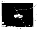
- the diameter is measured as shown in Fig. 8 .
- oxygen and sulfur are observed by mapping using a surface analysis by a scanning electronic microscope with an energy dispersive X-ray analysis (EDX) per 1 mm x 1 mm field of view of the surface of the copper foil.
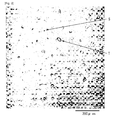
- Fig. 8 shows a mapping of oxygen.
- an area with a highest concentration of oxygen or sulfur (symbol R in Fig. 8 ) is selected within a mapping area, and a line analysis (symbol LN in Fig. 8 ) having a length of 10 ⁇ m is performed across the area. This is because the line analysis has a high measurement accuracy in an element concentration whereas the mapping is difficult to determine an absolute value of the element concentration accurately.
- a lowest concentration value of oxygen or sulfur is defined as a basis.
- a position having the concentration is 5% by mass higher than the basis is collated with the mapping.
- a color tone in the position having the concentration is 5% by mass higher than the basis within a mapping area is determined.
- the position having the higher concentration than the color tone i.e., the position having the concentration is 5% by mass higher than the basis
- an aggregate(a contour U in Fig. 8 ) of the position having the concentration is 5% by mass higher than the basis is determined to be regarded as the area of the oxide or the sulfide.
- a maximum length M and a length T in its vertical direction of the area are measured, and an average value of these values is determineed.
- the average value is considered as a diameter of the oxide or the sulfide.
- a total number of the oxide and the sulfide having the diameter of 0.5 ⁇ m or more is 15/mm 2 or less.
- the copper foil includes the oxide and the sulfide each having a diameter of 0.5 ⁇ m or more having a total number of 100/mm 2 or less measured for an area having a total area of 3 mm 2 within a depth of 10 ⁇ m from a surface that is a cross-section in parallel with a rolling direction and vertical to a rolling surface by using a scanning electronic microscope before heating at 1000 °C for 1 hour in an atmosphere containing 20 % by volume or more of hydrogen and balance argon.
- the oxide or the sulfide in the copper foil is heated at about 1000 °C, irregularity is generated on the surface of the copper foil.
- the oxide or the sulfide can be measured on the cross-section of the copper foil.
- the reason why the depth from the surface to 10 ⁇ m is measured is that the irregularity is less generated on the surface of the copper foil if the oxide or the sulfide is present distant from the surface of the copper foil.
- a measuring method and a counting method of the oxide and the sulfide is the same in the first aspect of the invention.
- the cross-section may be acquired at any position of the copper foil.
- the irregularity generated on the surface of the copper foil after heating at 1000 °C for 1 hour in an atmosphere containing 20 % by volume or more of hydrogen and balance argon is defined as follows: Firstly, the surface of the copper foil (1 mm 2 ) after heating at 1000 °C for 1 hour in an atmosphere containing 20 % by volume or more of hydrogen and balance argon is measured by using a confocal microscope to provide information point by point in a height direction of a granular part surrounded by a contour in a two dimensional image of the surface obtained. On the software of the confocal microscope, when a predetermined position of the two dimensional image is designated, the height information at the position can be outputted.
- Fig. 2 is the two dimensional image showing an example of a confocal microscope image of the surface of the copper foil.
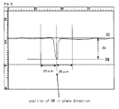
- Fig. 3 shows a height profile of the granular part as an S point (corresponds to the dent portion) in Fig. 2 .
- the dent portion having a depth ds of 1.5 ⁇ m or more is countered.
- the number of the dent portion should be 20/mm 2 or less.
- the irregularity generated on the surface of the copper foil after heating at 1000 °C for 1 hour in an atmosphere containing 20 % by volume or more of hydrogen and balance argon is defined as follows: Firstly, similar to the third invention, the surface of the copper foil (1 mm 2 ) after heating at 1000 °C for 1 hour is measured by using a confocal microscope to provide information point by point in a height direction of a granular part surrounded by a contour in a two dimensional image of the surface obtained.
- Fig. 2 shows an example of a confocal microscope image of the surface of the copper foil.
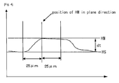
- Fig. 4 shows height information of the granular part as a T point (corresponds to the convex portion) in Fig. 2 .
- the convex portion having a height dt of 1.5 ⁇ m or more is countered.
- the number of the convex portion should be 100/mm 2 or less.
- the maximum value of the ds is preferably 14 ⁇ m or less, more preferably, 10 ⁇ m or less, and most preferably 6 ⁇ m or less.
- the maximum value of the dt is preferably 16 ⁇ m or less, more preferably, 10 ⁇ m or less, and most preferably 6 ⁇ m or less.
- TPC tough pitch copper
- OF oxygen free copper
- a composition containing 0.050 % by mass or less of one or more of elements selected from the group consisting of Sn and Ag can be used.
- the copper foil can have improved strength and adequate elongation, and the grain size can be increased. If a content percentage of the above-described elements exceeds 0.050 % by mass, the strength may be further increased, but the elongation may be decreased to degrade workability and suppress the growth of the grain size. More preferably, the content percentage of the above-described elements is 0.040 % by mass or less.
- a lower limit of the content percentage of the above-described elements is not especially limited, for example the lower limit may be 0.001 % by mass, or the lower limit may be 0.005 % by mass. If the content percentage of the above-described elements is less than 0.001 % by mass, the content percentage may be difficult to be controlled.
- a concentration of Cu in the copper foil is preferably 99.95 to 99.995% by mass. If the concentration of copper foil is less than 99.95% by mass, the oxide or the sulfide is easily present on the surface of the copper foil and the irregularity of the surface of the copper foil may be large, as described above. On the other hand, if the Cu concentration in the copper foil is high, the production costs become high and the strength is decreased, whereby it is difficult to produce the foil and to provide the large area. In view of the above, it is preferable that the concentration of Cu in the copper foil be 99.995% by mass or less.
- the thickness of the copper foil is not especially limited, but is generally 5 to 150 ⁇ m.
- the thickness of the copper foil is 12 to 50 ⁇ m for ease of etching and removal as described later while assuring handleability. If the thickness of the copper foil is less than 12 ⁇ m, it may be easily broken and have less handleability. If the thickness exceeds 50 ⁇ m, etching and removal may be difficult.
- the copper foil for producing graphene according to the embodiment of the present invention can be produced as follows, for example: Firstly, a copper ingot having a predetermined composition is produced, is hot rolled, and is annealed and cold rolled repeatedly to provide a rolled sheet. The rolled sheet is annealed to be recrystallized, and finally cold rolled to the predetermined thickness of a rolling reduction of 80 to 99.9% (preferably 85 to 99.9%, more preferably 90 to 99.9%), thereby providing a copper foil.
- the surface of the copper foil becomes advantageously smooth.
- the degree of smoothness of the surface of the copper foil can be represented by the degree of gloss on the surface of the copper foil.
- an oil pit (the irregularity) is generated as the phenomenon upon rolling on a rolling processed surface when the oil film that is introduced between the roll and the material is thick.
- an oil pit is generated as the phenomenon upon rolling on a rolling processed surface when the oil film that is introduced between the roll and the material is thick.
- an oil pit is thin, an area that is contacted with the rolling roll on the surface of the material is increased.
- free deformation is limited, the oil pit does not grown, a smooth surface profile of the rolling roll is transferred and a smooth surface is formed. Because of this, as an indicator of the thin oil film, the oil film equivalent is limited to 18000 or less. If the oil film equivalent exceeds 18000, a base roughness of the surface of the copper foil may exceed 20 ⁇ m.
- Oil film equivalent rolling oil viscosity , kinetic viscosity at 40 ⁇ °C , cSt x rolling speed ; m / min / yield stress of material ; kg / mm 2 x roll angle of bite ; rad
- the rolling oil viscosity (kinetic viscosity at 40°C) is low, the rolling speed is low, and the roll angle of bite (corresponding to a rolling reduction) is high.
- a rolling roll adjusted to have a roll diameter of 250 mm or less and surface roughness Ra roll of 0.1 ⁇ m or less (preferably 0.01 to 0.04 ⁇ m, more preferably 0.01 to 0.02 ⁇ m)
- rolling oil having a viscosity of 3 to 8 cSt preferably 3 to 5 cSt, more preferably 3 to 4 cSt is used.
- a rolling speed may be 100 to 500 m/min (preferably 200 to 450 m/min, more preferably 250 to 400 m/min), and the rolling reduction per pass may be 10 to 60%.
- the roll angle of bite is, for example, 0.001 to 0.04 rad, preferably 0.002 to 0.03 rad, more preferably 0.003 to 0.03 rad.
- the surface roughness Pa roll of the rolling roll exceeds 0.1 ⁇ m, the irregularity of the roll surface is transferred and smoothness of the material surface is impaired.
- a surface flatness having no oil pit can have a wide area.
- the viscosity of the rolling oil exceeds 8 cSt, the oil film equivalent is increased, thereby providing no surface gloss.
- the oil film equivalent is less than 3 cSt, rolling resistance is too increased to increase the rolling reduction.
- the rolling speed exceeds 500 m/min, the oil amount introduced is increased, thereby decreasing the gloss.
- the rolling speed is less than 100 m/min, the rolling reduction is not sufficiently provided and it is inconvenience from the standpoint of the productivity.
- the rolling reduction exceeds 99.9%, work hardening is accelerated to lose deformation capability, and the rolling reduction in the last pass is not ensured.
- the rolling reduction is less than 80%, a rolling texture is not grown, thereby providing no surface flatness.
- the roll angle of bite exceeds 0.04 rad, a difference between a roll peripheral speed and a material speed becomes great to lose the smoothness of the material surface.
- the roll angle of bite is less than 0.002 rad, the oil enters between the rolling roll and the material to be rolled and the amount of the oil is too great to lubricate, thereby decreasing the gloss.
- the rolling reduction per pass is, for example, 20 to 40%, preferably 20 to 35%, more preferably 25 to 35%. If the rolling reduction exceeds 35%, the oil pit is produced, thereby decreasing the gloss. On the other hand, if the rolling reduction is less than 20%, the number of passes increases to degrade the productivity.
- a material temperature is increased during the final cold rolling.
- the material temperature is such that oil lubricity is not lost or the copper foil is not re-crystallized, and may be 120 °C or less, preferably 100 °C or less. If the material temperature is 50 °C or less, there is almost no effect to smooth the surface of the copper foil.
- 60 degree gloss (JIS Z8741) of the copper foil is preferably 400% or more, and more preferably 500% or more both in a rolling direction and a direction transverse to rolling direction.
- the graphene is needed to be transferred from the copper foil to a transfer sheet. It is found that when a surface of the copper foil is rough, it is difficult to be transferred, and the graphene may be broken. Therefore, it is preferable that the surface irregularity of the copper foil be smooth.
- An upper limit of the 60 degree gloss in a rolling direction and a direction transverse to rolling direction is not especially limited.
- the upper limit is less than 500%, production conditions for rolling processing may not be strictly specified upon the production of the copper foil, whereby advantageously increasing a degree of production freedom.
- the upper limit of the 60 degree gloss in a rolling direction and a direction transverse to rolling direction is about 800%.
- an average crystal grain size of the copper foil heated grows to 100 ⁇ m or more.
- the average crystal grain size of the copper foil is less than 100 ⁇ m, it makes an obstacle for growth of the graphene, and the graphene is difficult to be grown in a planar direction.
- the heating at 1000°C for 1 hour in an atmosphere containing 20 % by volume or more of hydrogen and balance argon is simulated for a condition of heating the copper foil for producing graphene at not less than a decomposition temperature of the carbon-containing gas when graphene is produced.
- the average crystal grain size is determined by measuring the copper foil with a cutting method by JIS H0501.
- the large area graphene can be produced at low costs and a high yield.
- the copper foil for producing graphene according to the embodiment of the present invention can be produced as follows, for example: Firstly, tough pitch copper (JIS-H3100) or oxygen free copper (JIS-H3100) is used as it is, or by adding the predetermined elements as necessary, a copper ingot is produced to have a purity of 99.95% by mass or more. The ingot is hot rolled, and is annealed and cold rolled repeatedly to provide a rolled sheet. The rolled sheet is annealed to be re-crystallized, and finally cold rolled to the predetermined thickness of a rolling reduction of 80 to 99.9% (preferably 85 to 99.9%, more preferably 90 to 99.9%), thereby providing a copper foil.
- JIS-H3100 tough pitch copper
- JIS-H3100 oxygen free copper
- the above-described copper foil 10 for producing graphene of the present invention is placed in a chamber (such as a vacuum chamber) 100 and is heated by a heater 104. At the same time, the pressure in the chamber 100 is reduced or the chamber 100 is vacuum-evacuated. Then, a carbon-containing gas G is fed to the chamber 100 through a gas supply inlet 102 ( Fig. 1(a) ).
- a carbon-containing gas G carbon dioxide, carbon monoxide, methane, ethane, propane, ethylene, acetylene, alcohol or the like is cited, but is not limited thereto. One or more of these gases may be mixed.
- the copper foil 10 for producing graphene may be heated at a decomposition temperature of the carbon-containing gas G or more.
- the temperature can be 1000°C or more.
- the carbon-containing gas G may be heated at the decomposition temperature or more within the chamber 100, and the decomposed gas may bring into contact with the copper foil 10 for producing graphene.
- the decomposition gas carbon gas
- graphene 20 is formed on the surface of the copper foil 10 for producing graphene ( Fig. 1(b) ).
- the copper foil 10 for producing graphene is cooled to normal temperature, a transfer sheet 30 is laminated on the surface of the graphene 20, and the graphene 20 is transferred to the transfer sheet 30.
- the laminate is continuously immersed into an etching tank 110 via a sink roll 120, and the copper foil 10 for producing graphene is removed by etching ( Fig. 1 (c) ). In this way, the graphene 20 laminated on the predetermined transfer sheet 30 can be produced.
- the laminate from which the copper foil 10 for producing graphene is removed is pulled up, and a substrate 40 is laminated on the graphene 20. While the graphene 20 is transferred to the substrate 40, the transfer sheet 30 is removed, whereby the graphene 20 laminated on the substrate 40 can be produced.
- the transfer sheet 30 a variety of resin sheets (a polymer sheet such as polyethylene, polyurethane etc.) can be used.
- a sulfuric acid solution a sodium persulfate solution, a hydrogen peroxide and sodium persulfate solution, or a solution where sulfuric acid is added to hydrogen peroxide can be, for example, used.
- an Si, SiC, Ni or Ni alloy can be, for example, used.
- a copper ingot having a composition shown in Table 1 was prepared, was hot rolled at 800 to 900°C, and was annealed in a continuous annealing line at 300 to 700°C and cold rolled, which was repeated one time, to provide a rolled sheet having a thickness of 1 to 2 mm.
- the rolled sheet was annealed and re-crystallized in the continuous annealing line at 600 to 800°C, and was finally cold rolled to a thickness of 7 to 50 ⁇ m of a rolling reduction of 95 to 99.7% to provide each copper foil in each Example and Comparative Example.
- the tough pitch copper (TPC) used in each Example and Comparative Examples 4 and 5 was produced by lowering the oxygen concentration in the heating gas in a step of melting raw materials in a shaft furnace. As an indicator of the oxygen concentration in the heating gas, a carbon monoxide concentration was measured such that the carbon monoxide concentration was 2 to 7%.
- each carbon monoxide concentration in the heating gas in the shaft furnace was 0.5 to 1.5%.
- the carbon monoxide concentration and the oxygen concentration was controlled by changing the flow rate of air fed to the fuel gas.
- oil film equivalents were adjusted to the values shown in Table 1 both at a final pass of the final cold rolling and a previous pass before the final pass of the final cold rolling.
- Oil film equivalent rolling oil viscosity , kinetic viscosity at 40 ⁇ °C , cSt x rolling speed ; m / min / yield stress of material ; kg / mm 2 x roll angle of bite ; rad
- the copper foil having the Cu purity of 99.9999% As to the copper foil having the Cu purity of 99.9999% (Reference Example 1), copper having a purity of 99.99999% or more was used as the raw material, was re-melted under vacuum, and was molded into a mold having a thickness of 30 mm and a width of 100 mm under vacuum to provide an ingot. The ingot was surface machined, pickling, rolled and heated repeatedly to have a thickness of 35 ⁇ m. As to the copper foil having the Cu purity of 99.999% (Reference Example 2), copper having a purity of 99.9999% or more was used as the raw material, was re-melted under vacuum to provide an ingot. Thereafter, the sample was produced similar to Reference Example 1.
- Arithmetic mean deviation of assessed profile (Ra: ⁇ m) in accordance with JIS-B0601 and a total height of profile (Rt: ⁇ m) were measured per 1 mm x 1 mm field of view by a confocal microscope (manufactured by Lasertec Corporation, model No.: HD100D).
- the Sm is defined as " Mean width of the profile elements" by JIS B0601-2001 (in accordance with ISO4287-1997) that represents a surface texture by a profile curve method, and refers to an average of profile lengths of respective irregularities in a sampling length.
- the number of the oxide and the sulfide each having a diameter of 0.5 ⁇ m or more were measured per 1 mm x 1 mm field of view of the surface of the copper foil not heated using a scanning electronic microscope with an energy dispersive X-ray analysis (EDX) by the above-described method.
- EDX energy dispersive X-ray analysis
- Any cross-section parallel to the rolling direction of the copper foil not heated was produced.
- An area having a total area of 3 mm 2 within a depth of 10 ⁇ m from a surface was measured for an elemental analysis by the scanning electronic microscope to measure the number of the oxide and the sulfide each having a diameter of 0.5 ⁇ m or more by the above-described method.
- the surface of the copper foil (1 mm 2 ) after heating at 1000 °C for 1 hour in an atmosphere containing 20 % by volume or more of hydrogen and balance argon was measured by the confocal microscope (manufactured by Lasertec Corporation, model No.: HD100D, analysis software: LM eye (manufactured by Lasertec Corporation), scan timer: 60sec) to provide a two dimensional image. Information in a height direction of a granular part surrounded by a contour in the two dimensional image of the surface obtained was determined point by point. On the software of the confocal microscope, when a predetermined position of the two dimensional image is designated, the height information at the position can be outputted.
- Fig. 2 shows an example of a confocal microscope image of the surface of the copper foil.
- Fig. 3 shows a height profile of the granular part as an S point (corresponds to the dent portion) in Fig. 2 .
- Fig. 4 shows height information of the granular part as a T point (corresponds to the convex portion) in Fig. 2 .
- the ds or dt of 1.5 ⁇ m or more was counted as the dent portion or the convex portion.
- the copper foil for producing graphene (horizontal and vertical of 100 x 100 mm) in each Example was wound around an inner wall of a quartz tube (3 inches) within an infrared image furnace and was vacuumed (pressure: 0.2 Torr). Next, while a mixed gas of hydrogen and argon was flowed into the quartz tube, the infrared image furnace was heated to 1000 °C. In addition, methane gas (feed gas flow rate: 10 to 100 cc/min) was flowed thereinto, which was held for one hour, and the reaction was thus performed.
- a PET film was adhered to the copper foil at a graphene side where graphene was grown on the surface, and the copper foil was etched and removed by acid. Thereafter, a sheet resistance of graphene was measured by a four probe method. A reaction time was determined by finding out the relationship between the reaction time and the sheet resistance in advance and was the time needed for stabilizing the sheet resistance.
- Each of Reference Examples 1 and 2 was the copper foil produced by decreasing an impurity amount of high purity copper (99.999%) using vacuum melting and had the total number of the oxide and the sulfide on the surface of 15/mm 2 or less.
- the production costs were high, a wide copper foil was difficult to be produced, and practicability was low.
- Fig. 5 shows a three dimensional image of the confocal microscope image in Fig. 2 .
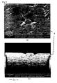
- Fig. 6 (a) shows an SEM image of a surface of the sample in Example 6 before heating.
- Fig. 6 (b) shows a cross-section SEM image thereof. Viewing the cross-section of a detection section (symbol A) of the oxide reveals that the oxide was somewhat internally present rather than on the surface.
- Fig. 7 (a) shows an SEM image of a surface of the sample in Example 6 after heating.
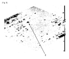
- Fig. 7(b) shows a cross-section SEM image thereof. Viewing the cross-section of the convex section (symbol B) reveals that the oxide was reduced, heated and evaporated, thereby raising the copper foil material on the surface.
Landscapes
- Chemical & Material Sciences (AREA)
- Engineering & Computer Science (AREA)
- Organic Chemistry (AREA)
- Materials Engineering (AREA)
- Nanotechnology (AREA)
- Mechanical Engineering (AREA)
- Physics & Mathematics (AREA)
- Crystallography & Structural Chemistry (AREA)
- Metallurgy (AREA)
- Condensed Matter Physics & Semiconductors (AREA)
- General Physics & Mathematics (AREA)
- Inorganic Chemistry (AREA)
- Chemical Kinetics & Catalysis (AREA)
- Manufacturing & Machinery (AREA)
- Thermal Sciences (AREA)
- Composite Materials (AREA)
- Carbon And Carbon Compounds (AREA)
- Metal Rolling (AREA)
- ing And Chemical Polishing (AREA)
- Laminated Bodies (AREA)
Abstract
Description
- The present invention relates to a copper foil for producing graphene, and a method of producing graphene using the same.
- Graphite has a layered structure where a plurality of layers of carbon six-membered rings planarly arranged is laminated. The graphite having a mono atomic layer or around several atomic layers is called as graphene or a graphene sheet. The graphene sheet has own electrical, optical and mechanical properties, and in particularly has a high carrier mobility speed. Therefore, the graphene sheet has expected to be applied in various industries as a fuel cell separator, a transparent electrode, a conductive thin film for a display device, a "mercury-free" fluorescent lamp, a composite material, a carrier for Drug Delivery System (DDS) etc.
- As a method of producing the graphene sheet, it is known that graphite is peeled with an adhesion tape. However, there are problems in that the number of the layer(s) of the graphene sheet obtained is not uniform, a wide area graphene sheet is difficult to be provided, and it is not suitable for mass production.
- A technology has been developed that a sheet-like monocrystal graphitized metal catalyst is contacted with a carboneous substance and then is heat treated to grow the graphene sheet (Chemical Vapor Deposition (CVD) method) (Patent Literature 1). As the monocrystal graphitized metal catalyst, there is described a metal substrate made of Ni, Cu or W, for example.
- Similarly, a technology has been reported that a graphene film is formed by the chemical vapor deposition method on a copper layer formed on an Ni or Cu metal foil or an Si substrate. The graphene film is formed at about 1000°C (Non-Patent Literature 1).
- [Patent Literature 1] Japanese Unexamined Patent Publication (Kokai)
2009-143799 - [Non-Patent Literature 1] SCIENCE Vol. 324 (2009) P1312-1314
- However, it is not easy and spends high costs to produce the monocrystal metal substrate, a wide area substrate is difficult to be provided, and a wide area graphene sheet is thus difficult to be provided, as described in
Patent Document 1. On the other hand, Non-PatentDocument 1 describes that Cu is used as the substrate. Graphene is not grown on a copper foil in a plane direction within a short time. A Cu layer formed on an Si substrate is annealed to provide coarse grains, thereby providing a substrate. In this case, a size of graphene is limited to the size of the Si substrate, and its production costs are high, too. - Here, the reason for superiority of the copper as the catalyst of graphene growth is that the copper little dissolves carbon. When the copper acts as the catalyst, carbon atoms produced by thermal decomposition of a hydrocarbon gas form graphene on the surface of the copper. Once the copper is covered with graphene, the copper no longer acts as the catalyst. The hydrocarbon gas will not be further thermally decomposed, and a plurality of graphene layers is unlikely formed. Instead, a graphene monolayer is provided. In this regard, a copper monocrystal is good as a substrate for producing graphene. However, as the copper monocrystal is expensive and has a limited size, it is not suitable to form a large area graphene film.
- On the other hand, the copper foil can easily provide the large area. However, when the present inventor produced graphene using the copper foil as the substrate, it was found that a sheet resistance of graphene increased to degrade a quality.
- Accordingly, an object of the present invention is to provide a copper foil for producing graphene being capable of producing graphene having a large area with low costs, and a method of producing graphene using the same.
- A first aspect of the present invention provides a copper foil for producing graphene, including oxides and sulfides each having a diameter of 0.5 µm or more having a total number of 15/mm2 or less measured by using a scanning electronic microscope before heating at 1000 °C for 1 hour in an atmosphere containing 20 % by volume or more of hydrogen and balance argon.
- A second aspect of the present invention provides a copper foil for producing graphene, including oxides and sulfides each having a diameter of 0.5 µm or more having a total number of 100/mm2 or less measured for an area having a total area of 3 mm2 within a depth of 10 µm from a surface that is a cross-section in parallel to the rolling direction by using a scanning electronic microscope before heating at 1000 °C for 1 hour in an atmosphere containing 20 % by volume or more of hydrogen and balance argon.
- A third aspect of the present invention provides a copper foil for producing graphene, having a number of a dent portion being 20/mm2 or less, the dent portion having a depth ds of 1.5 µm or more being countered; ds = DS - DM; where DM is a lowest height by measuring 1 mm2 surface by using a confocal microscope and by each height profile of a granular part surrounded by a contour in the two dimensional image of the surface obtained; the 1 mm2 surface being heated at 1000 °C for 1 hour in an atmosphere containing 20 % by volume or more of hydrogen and balance argon, and DS is a highest height that is regarded as a base line in an area of ± 25 µm along a plane direction and a rolling direction from the position of DM.
- A fourth aspect of the present invention provides a copper foil for producing graphene, having a number of a convex portion being 100/mm2 or less, the convex portion having a height dt of 1.5 µm or more being countered; dt = HM-HS; where HM is a highest height by measuring 1 mm2 surface by using a confocal microscope and by each height profile of a granular part surrounded by a contour in the two dimensional image of the surface obtained; the 1 mm2 surface being heated at 1000 °C for 1 hour in an atmosphere containing 20 % by volume or more of hydrogen and balance argon, and HS is a lowest height that is regarded as a base line in an area of ± 25 µm in a plane direction and a rolling direction from the position of HM.
- Preferably, in the copper foil for producing graphene of the present invention, a purity of Cu is 99.95 to 99.995% by mass.
- Preferably, the copper foil for producing graphene of the present invention consists of tough pitch copper in accordance with JIS-H3100; or consists of oxygen free copper in accordance with JIS-H3100, or contains 0.050 % by mass or less of one or more of elements selected from the group consisting of Sn and Ag to the tough pitch copper or the oxygen free copper.
- Further, the present invention provides a method of producing grapheme using the copper foil for producing graphene, comprising the steps of: providing a carbon-containing gas while placing the heated copper foil to form graphene on a surface of the copper foil for producing graphene; laminating a transfer sheet on the surface of the graphene, and etching and removing the copper foil for producing graphene while transferring the graphene to the transfer sheet.
- According to the present invention, there can be provided a copper foil being capable of producing graphene having a large area with low costs.
-
- [
Fig. 1 ] A process chart showing a method of producing graphene according to an embodiment of the present invention. - [
Fig. 2 ] An example of a confocal microscope image of a surface of a copper foil. - [
Fig. 3 ] A height profile of a granular part at point S (corresponds to a dent portion) inFig. 2 . - [
Fig. 4 ] A height profile of a granular part at point T (corresponds to a convex portion) inFig. 2 . - [
Fig. 5 ] A three dimensional image of the confocal microscope image inFig. 2 . - [
Fig. 6 ] An SEM image of a surface and a cross-section of a sample in Example 6 before heating. - [
Fig. 7 ] An SEM image of a surface and a cross-section of a sample in Example 6 after heating. - [
Fig. 8 ] A mapping of oxygen by a surface analysis using a scanning electronic microscope. - Hereinafter, a copper foil for producing graphene and a method of producing graphene according to an embodiment of the present invention will be described. The symbol "%" herein refers to % by mass, unless otherwise specified.
- According to a first aspect of the invention, a copper foil includes an oxide and a sulfide each having a diameter of 0.5 µm or more having a total number of 15/mm2 or less measured by using a scanning electronic microscope before heating at 1000 °C for 1 hour in an atmosphere containing 20 % by volume or more of hydrogen and balance argon.
- The present inventor sought the cause of the increase in the sheet resistance of graphene and the poor quality when graphene is produced using the copper foil as the substrate, and found that the copper foil is uneven, thereby inhibiting the growth of graphene. Specifically, each carbon atom bond in graphene is in the order of nm, but a surface irregularity of the surface of the copper foil is in the order of µm. It is contemplated that when the surface irregularity (unevenness) of the surface of the copper foil is large, the carbon atom bonds in graphene are cut, resulting in the high sheet resistance.
- If a high purity copper foil including over 99.995% by mass of Cu is used, there can be provided a smooth copper foil having low surface unevenness. However, the copper foil is produced at high costs and has a limited size.
- The present inventor found that when the oxide and the sulfide of the copper foil containd in an ingot to manufacture the copper foil by rolling are heated at a temperature of around 1000°C where graphene is produced, bulges, scoops or pits are generated to induce the irregularity on the surface of the copper foil. Based on the findings, by limiting the size and the number of the oxide and the sulfide present on the surface of the copper foil (or within the copper foil), high quality graphene can be produced.
- A reason why the oxide and the sulfide are specified before heating at 1000 °C for 1 hour in an atmosphere containing 20 % by volume or more of hydrogen and balance argon is that the oxide and the sulfide present near the surface of the copper foil evaporate in the vicinity of 1000 °C as described above, and the surface of the copper foil is broken to generate bulges, scoops or pits.
- In addition, a reason why the oxide and the sulfide are specified each having a diameter of 0.5 µm or more is that the oxide and the sulfide each having a diameter of 0.5 µm or more easily generate the irregularity on the surface of the copper foil.
- Herein, the diameter is measured as shown in
Fig. 8 . Firstly, oxygen and sulfur are observed by mapping using a surface analysis by a scanning electronic microscope with an energy dispersive X-ray analysis (EDX) per 1 mm x 1 mm field of view of the surface of the copper foil.Fig. 8 shows a mapping of oxygen. Next, an area with a highest concentration of oxygen or sulfur (symbol R inFig. 8 ) is selected within a mapping area, and a line analysis (symbol LN inFig. 8 ) having a length of 10 µm is performed across the area. This is because the line analysis has a high measurement accuracy in an element concentration whereas the mapping is difficult to determine an absolute value of the element concentration accurately. - Then, in the line analysis, a lowest concentration value of oxygen or sulfur is defined as a basis. A position having the concentration is 5% by mass higher than the basis is collated with the mapping. A color tone in the position having the concentration is 5% by mass higher than the basis within a mapping area is determined. The position having the higher concentration than the color tone (i.e., the position having the concentration is 5% by mass higher than the basis) is regarded as the oxide or the sulfide. On the mapping area, an aggregate(a contour U in
Fig. 8 ) of the position having the concentration is 5% by mass higher than the basis is determined to be regarded as the area of the oxide or the sulfide. A maximum length M and a length T in its vertical direction of the area are measured, and an average value of these values is determineed. The average value is considered as a diameter of the oxide or the sulfide. A total number of the oxide and the sulfide having the diameter of 0.5 µm or more is 15/mm2 or less. - According to a second aspect of the invention, the copper foil includes the oxide and the sulfide each having a diameter of 0.5 µm or more having a total number of 100/mm2 or less measured for an area having a total area of 3 mm2 within a depth of 10 µm from a surface that is a cross-section in parallel with a rolling direction and vertical to a rolling surface by using a scanning electronic microscope before heating at 1000 °C for 1 hour in an atmosphere containing 20 % by volume or more of hydrogen and balance argon.
- Similar to the first invention as described above, when the oxide or the sulfide in the copper foil is heated at about 1000 °C, irregularity is generated on the surface of the copper foil. The oxide or the sulfide can be measured on the cross-section of the copper foil.
- Here, the reason why the depth from the surface to 10 µm is measured is that the irregularity is less generated on the surface of the copper foil if the oxide or the sulfide is present distant from the surface of the copper foil. A measuring method and a counting method of the oxide and the sulfide is the same in the first aspect of the invention. In addition, as the oxide and the sulfide are dispersed relatively uniformly within the copper foil, the cross-section may be acquired at any position of the copper foil.
- According to a third aspect of the invention, the irregularity generated on the surface of the copper foil after heating at 1000 °C for 1 hour in an atmosphere containing 20 % by volume or more of hydrogen and balance argon is defined as follows: Firstly, the surface of the copper foil (1 mm2) after heating at 1000 °C for 1 hour in an atmosphere containing 20 % by volume or more of hydrogen and balance argon is measured by using a confocal microscope to provide information point by point in a height direction of a granular part surrounded by a contour in a two dimensional image of the surface obtained. On the software of the confocal microscope, when a predetermined position of the two dimensional image is designated, the height information at the position can be outputted.
-
Fig. 2 is the two dimensional image showing an example of a confocal microscope image of the surface of the copper foil.Fig. 3 shows a height profile of the granular part as an S point (corresponds to the dent portion) inFig. 2 . A depth ds of the dent portion is determined by the equation: ds = DS - DM; where DM is a lowest height, and DS is a highest height that is regarded as a base line in an area of ± 25 µm along a plane direction and a rolling direction from the position of DM. - The dent portion having a depth ds of 1.5 µm or more is countered. The number of the dent portion should be 20/mm2 or less.
- If the number of the dent portion exceeds 20/mm2, the irregularity of the surface of the copper foil becomes remarkable and it is difficult to produce high quality graphene.
- According to a fourth aspect of the invention, the irregularity generated on the surface of the copper foil after heating at 1000 °C for 1 hour in an atmosphere containing 20 % by volume or more of hydrogen and balance argon is defined as follows: Firstly, similar to the third invention, the surface of the copper foil (1 mm2) after heating at 1000 °C for 1 hour is measured by using a confocal microscope to provide information point by point in a height direction of a granular part surrounded by a contour in a two dimensional image of the surface obtained.
-
Fig. 2 shows an example of a confocal microscope image of the surface of the copper foil.Fig. 4 shows height information of the granular part as a T point (corresponds to the convex portion) inFig. 2 . A height dt of the convex portion is determined by the equation: dt = HM - HS; where HM is a highest height, and HS is a lowest height that is regarded as a base line in an area of ± 25 µm in a plane direction and a rolling direction from the position of HM. - The convex portion having a height dt of 1.5 µm or more is countered. The number of the convex portion should be 100/mm2 or less.
- If the number of the convex portion exceeds 100/mm2, the irregularity of the surface of the copper foil becomes remarkable and it is difficult to produce high quality graphene.
- The maximum value of the ds is preferably 14 µm or less, more preferably, 10 µm or less, and most preferably 6 µm or less. The maximum value of the dt is preferably 16 µm or less, more preferably, 10 µm or less, and most preferably 6 µm or less.
- As the copper foil, tough pitch copper (TPC) in accordance with JIS-H3100 or oxygen free copper (OFC) in accordance with JIS-H3100 can be used.
- In addition, to the tough pitch copper or the oxygen free copper, a composition containing 0.050 % by mass or less of one or more of elements selected from the group consisting of Sn and Ag can be used. When the above-described elements are contained, the copper foil can have improved strength and adequate elongation, and the grain size can be increased. If a content percentage of the above-described elements exceeds 0.050 % by mass, the strength may be further increased, but the elongation may be decreased to degrade workability and suppress the growth of the grain size. More preferably, the content percentage of the above-described elements is 0.040 % by mass or less.
- Although a lower limit of the content percentage of the above-described elements is not especially limited, for example the lower limit may be 0.001 % by mass, or the lower limit may be 0.005 % by mass. If the content percentage of the above-described elements is less than 0.001 % by mass, the content percentage may be difficult to be controlled.
- A concentration of Cu in the copper foil is preferably 99.95 to 99.995% by mass. If the concentration of copper foil is less than 99.95% by mass, the oxide or the sulfide is easily present on the surface of the copper foil and the irregularity of the surface of the copper foil may be large, as described above. On the other hand, if the Cu concentration in the copper foil is high, the production costs become high and the strength is decreased, whereby it is difficult to produce the foil and to provide the large area. In view of the above, it is preferable that the concentration of Cu in the copper foil be 99.995% by mass or less.
- The thickness of the copper foil is not especially limited, but is generally 5 to 150 µm. Preferably, the thickness of the copper foil is 12 to 50 µm for ease of etching and removal as described later while assuring handleability. If the thickness of the copper foil is less than 12 µm, it may be easily broken and have less handleability. If the thickness exceeds 50 µm, etching and removal may be difficult.
- The copper foil for producing graphene according to the embodiment of the present invention can be produced as follows, for example: Firstly, a copper ingot having a predetermined composition is produced, is hot rolled, and is annealed and cold rolled repeatedly to provide a rolled sheet. The rolled sheet is annealed to be recrystallized, and finally cold rolled to the predetermined thickness of a rolling reduction of 80 to 99.9% (preferably 85 to 99.9%, more preferably 90 to 99.9%), thereby providing a copper foil.
- Here, when the oil film equivalent is 18000 or less both at a final pass of the final cold rolling and at a previous pass before the final pass of the final cold rolling, the surface of the copper foil becomes advantageously smooth.
- When the surface of the copper foil is smooth, it is preferable for growing the crystal grains annealed. The degree of smoothness of the surface of the copper foil can be represented by the degree of gloss on the surface of the copper foil. Specifically, an oil pit (the irregularity) is generated as the phenomenon upon rolling on a rolling processed surface when the oil film that is introduced between the roll and the material is thick. When the oil film is thin, an area that is contacted with the rolling roll on the surface of the material is increased. As a result, free deformation is limited, the oil pit does not grown, a smooth surface profile of the rolling roll is transferred and a smooth surface is formed. Because of this, as an indicator of the thin oil film, the oil film equivalent is limited to 18000 or less. If the oil film equivalent exceeds 18000, a base roughness of the surface of the copper foil may exceed 20 µm.
- The oil film equivalent is represented by the following equation:

- In order to limit the oil film equivalent to 18000 or less, it is preferable that the rolling oil viscosity (kinetic viscosity at 40°C) is low, the rolling speed is low, and the roll angle of bite (corresponding to a rolling reduction) is high. For example, by a rolling roll adjusted to have a roll diameter of 250 mm or less and surface roughness Raroll of 0.1 µm or less (preferably 0.01 to 0.04 µm, more preferably 0.01 to 0.02 µm), rolling oil having a viscosity of 3 to 8 cSt (preferably 3 to 5 cSt, more preferably 3 to 4 cSt) is used. A rolling speed may be 100 to 500 m/min (preferably 200 to 450 m/min, more preferably 250 to 400 m/min), and the rolling reduction per pass may be 10 to 60%. The roll angle of bite is, for example, 0.001 to 0.04 rad, preferably 0.002 to 0.03 rad, more preferably 0.003 to 0.03 rad.
- If the surface roughness Paroll of the rolling roll exceeds 0.1 µm, the irregularity of the roll surface is transferred and smoothness of the material surface is impaired. By rolling under the above-described conditions, a surface flatness having no oil pit can have a wide area. If the viscosity of the rolling oil exceeds 8 cSt, the oil film equivalent is increased, thereby providing no surface gloss. On the other hand, if the oil film equivalent is less than 3 cSt, rolling resistance is too increased to increase the rolling reduction. If the rolling speed exceeds 500 m/min, the oil amount introduced is increased, thereby decreasing the gloss. On the other hand, if the rolling speed is less than 100 m/min, the rolling reduction is not sufficiently provided and it is inconvenience from the standpoint of the productivity.
- If the rolling reduction exceeds 99.9%, work hardening is accelerated to lose deformation capability, and the rolling reduction in the last pass is not ensured. On the other hand, if the rolling reduction is less than 80%, a rolling texture is not grown, thereby providing no surface flatness. If the roll angle of bite exceeds 0.04 rad, a difference between a roll peripheral speed and a material speed becomes great to lose the smoothness of the material surface. On the other hand, the roll angle of bite is less than 0.002 rad, the oil enters between the rolling roll and the material to be rolled and the amount of the oil is too great to lubricate, thereby decreasing the gloss.
- The rolling reduction per pass is, for example, 20 to 40%, preferably 20 to 35%, more preferably 25 to 35%. If the rolling reduction exceeds 35%, the oil pit is produced, thereby decreasing the gloss. On the other hand, if the rolling reduction is less than 20%, the number of passes increases to degrade the productivity.
- Furthermore, as another method to smooth the surface of the copper foil, a material temperature is increased during the final cold rolling. When the material temperature is increased, dislocation recovery is induced to smooth the surface of the copper foil. The material temperature is such that oil lubricity is not lost or the copper foil is not re-crystallized, and may be 120 °C or less, preferably 100 °C or less. If the material temperature is 50 °C or less, there is almost no effect to smooth the surface of the copper foil.
- 60 degree gloss (JIS Z8741) of the copper foil is preferably 400% or more, and more preferably 500% or more both in a rolling direction and a direction transverse to rolling direction.
- As described later, after graphene is produced using the copper foil for producing graphene according to the present invention, the graphene is needed to be transferred from the copper foil to a transfer sheet. It is found that when a surface of the copper foil is rough, it is difficult to be transferred, and the graphene may be broken. Therefore, it is preferable that the surface irregularity of the copper foil be smooth.
- An upper limit of the 60 degree gloss in a rolling direction and a direction transverse to rolling direction is not especially limited. When the upper limit is less than 500%, production conditions for rolling processing may not be strictly specified upon the production of the copper foil, whereby advantageously increasing a degree of production freedom. Practically, the upper limit of the 60 degree gloss in a rolling direction and a direction transverse to rolling direction is about 800%.
- By heating the copper foil after the final cold rolling at 1000°C for 1 hour in an atmosphere containing 20 % by volume or more of hydrogen and balance argon, an average crystal grain size of the copper foil heated grows to 100 µm or more.
- If the average crystal grain size of the copper foil is less than 100 µm, it makes an obstacle for growth of the graphene, and the graphene is difficult to be grown in a planar direction.
- The heating at 1000°C for 1 hour in an atmosphere containing 20 % by volume or more of hydrogen and balance argon is simulated for a condition of heating the copper foil for producing graphene at not less than a decomposition temperature of the carbon-containing gas when graphene is produced.
- Further, the average crystal grain size is determined by measuring the copper foil with a cutting method by JIS H0501.
- Using the copper foil for producing graphene as specified above, the large area graphene can be produced at low costs and a high yield.
- The copper foil for producing graphene according to the embodiment of the present invention can be produced as follows, for example: Firstly, tough pitch copper (JIS-H3100) or oxygen free copper (JIS-H3100) is used as it is, or by adding the predetermined elements as necessary, a copper ingot is produced to have a purity of 99.95% by mass or more. The ingot is hot rolled, and is annealed and cold rolled repeatedly to provide a rolled sheet. The rolled sheet is annealed to be re-crystallized, and finally cold rolled to the predetermined thickness of a rolling reduction of 80 to 99.9% (preferably 85 to 99.9%, more preferably 90 to 99.9%), thereby providing a copper foil.
- Next, referring to
Fig. 1 , a method of producing graphene according to the embodiment of the present invention will be described. - First, the above-described
copper foil 10 for producing graphene of the present invention is placed in a chamber (such as a vacuum chamber) 100 and is heated by aheater 104. At the same time, the pressure in thechamber 100 is reduced or thechamber 100 is vacuum-evacuated. Then, a carbon-containing gas G is fed to thechamber 100 through a gas supply inlet 102 (Fig. 1(a) ). As the carbon-containing gas G, carbon dioxide, carbon monoxide, methane, ethane, propane, ethylene, acetylene, alcohol or the like is cited, but is not limited thereto. One or more of these gases may be mixed. Thecopper foil 10 for producing graphene may be heated at a decomposition temperature of the carbon-containing gas G or more. For example, the temperature can be 1000°C or more. Alternatively, the carbon-containing gas G may be heated at the decomposition temperature or more within thechamber 100, and the decomposed gas may bring into contact with thecopper foil 10 for producing graphene. - Then, the decomposition gas (carbon gas) is contacted with the surface of the
copper foil 10 for producing grapheme, andgraphene 20 is formed on the surface of thecopper foil 10 for producing graphene (Fig. 1(b) ). - Then, the
copper foil 10 for producing graphene is cooled to normal temperature, atransfer sheet 30 is laminated on the surface of thegraphene 20, and thegraphene 20 is transferred to thetransfer sheet 30. Next, the laminate is continuously immersed into anetching tank 110 via asink roll 120, and thecopper foil 10 for producing graphene is removed by etching (Fig. 1 (c) ). In this way, thegraphene 20 laminated on thepredetermined transfer sheet 30 can be produced. - In addition, the laminate from which the
copper foil 10 for producing graphene is removed is pulled up, and asubstrate 40 is laminated on thegraphene 20. While thegraphene 20 is transferred to thesubstrate 40, thetransfer sheet 30 is removed, whereby thegraphene 20 laminated on thesubstrate 40 can be produced. - As the
transfer sheet 30, a variety of resin sheets (a polymer sheet such as polyethylene, polyurethane etc.) can be used. As an etching reagent for etching and removing thecopper foil 10 for producing graphene, a sulfuric acid solution, a sodium persulfate solution, a hydrogen peroxide and sodium persulfate solution, or a solution where sulfuric acid is added to hydrogen peroxide can be, for example, used. As thesubstrate 40, an Si, SiC, Ni or Ni alloy can be, for example, used. - A copper ingot having a composition shown in Table 1 was prepared, was hot rolled at 800 to 900°C, and was annealed in a continuous annealing line at 300 to 700°C and cold rolled, which was repeated one time, to provide a rolled sheet having a thickness of 1 to 2 mm. The rolled sheet was annealed and re-crystallized in the continuous annealing line at 600 to 800°C, and was finally cold rolled to a thickness of 7 to 50 µm of a rolling reduction of 95 to 99.7% to provide each copper foil in each Example and Comparative Example.
- The tough pitch copper (TPC) used in each Example and Comparative Examples 4 and 5 was produced by lowering the oxygen concentration in the heating gas in a step of melting raw materials in a shaft furnace. As an indicator of the oxygen concentration in the heating gas, a carbon monoxide concentration was measured such that the carbon monoxide concentration was 2 to 7%.
- In the tough pitch copper used in Comparative Examples 1 to 3, each carbon monoxide concentration in the heating gas in the shaft furnace was 0.5 to 1.5%.
- The carbon monoxide concentration and the oxygen concentration was controlled by changing the flow rate of air fed to the fuel gas.
- Here, the oil film equivalents were adjusted to the values shown in Table 1 both at a final pass of the final cold rolling and a previous pass before the final pass of the final cold rolling.
- The oil film equivalent is represented by the following equation:

- As to the copper foil having the Cu purity of 99.9999% (Reference Example 1), copper having a purity of 99.99999% or more was used as the raw material, was re-melted under vacuum, and was molded into a mold having a thickness of 30 mm and a width of 100 mm under vacuum to provide an ingot. The ingot was surface machined, pickling, rolled and heated repeatedly to have a thickness of 35µm. As to the copper foil having the Cu purity of 99.999% (Reference Example 2), copper having a purity of 99.9999% or more was used as the raw material, was re-melted under vacuum to provide an ingot. Thereafter, the sample was produced similar to Reference Example 1.
- After final cold-rolling and heating of the copper foil in each Example and Comparative Example at 1000 °C for 1 hour in an atmosphere containing 20 % by volume or more of hydrogen and balance argon, a surface roughness was measured.
- Arithmetic mean deviation of assessed profile (Ra: µm) in accordance with JIS-B0601 and a total height of profile (Rt: µm) were measured per 1 mm x 1 mm field of view by a confocal microscope (manufactured by Lasertec Corporation, model No.: HD100D). The Sm is defined as "Mean width of the profile elements" by JIS B0601-2001 (in accordance with ISO4287-1997) that represents a surface texture by a profile curve method, and refers to an average of profile lengths of respective irregularities in a sampling length.
- The number of the oxide and the sulfide each having a diameter of 0.5 µm or more were measured per 1 mm x 1 mm field of view of the surface of the copper foil not heated using a scanning electronic microscope with an energy dispersive X-ray analysis (EDX) by the above-described method.
- Any cross-section parallel to the rolling direction of the copper foil not heated was produced. An area having a total area of 3 mm2 within a depth of 10 µm from a surface was measured for an elemental analysis by the scanning electronic microscope to measure the number of the oxide and the sulfide each having a diameter of 0.5 µm or more by the above-described method.
- The surface of the copper foil (1 mm2) after heating at 1000 °C for 1 hour in an atmosphere containing 20 % by volume or more of hydrogen and balance argon was measured by the confocal microscope (manufactured by Lasertec Corporation, model No.: HD100D, analysis software: LM eye (manufactured by Lasertec Corporation), scan timer: 60sec) to provide a two dimensional image. Information in a height direction of a granular part surrounded by a contour in the two dimensional image of the surface obtained was determined point by point. On the software of the confocal microscope, when a predetermined position of the two dimensional image is designated, the height information at the position can be outputted.
-
Fig. 2 shows an example of a confocal microscope image of the surface of the copper foil.Fig. 3 shows a height profile of the granular part as an S point (corresponds to the dent portion) inFig. 2 . A depth ds of the dent portion is determined by the equation: ds = DS - DM; where DM is a lowest height, and DS is a highest height that is regarded as a base line in an area of ± 25 µm along a plane direction and a rolling direction from the position of DM.Fig. 4 shows height information of the granular part as a T point (corresponds to the convex portion) inFig. 2 . A height dt of the convex portion is determined by the equation: dt = HM - HS; where HM is a highest height, and HS is a lowest height that is regarded as a base line in an area of ± 25 µm along a plane direction and a rolling direction from the position of HM. - The ds or dt of 1.5 µm or more was counted as the dent portion or the convex portion.
- The copper foil for producing graphene (horizontal and vertical of 100 x 100 mm) in each Example was wound around an inner wall of a quartz tube (3 inches) within an infrared image furnace and was vacuumed (pressure: 0.2 Torr). Next, while a mixed gas of hydrogen and argon was flowed into the quartz tube, the infrared image furnace was heated to 1000 °C. In addition, methane gas (feed gas flow rate: 10 to 100 cc/min) was flowed thereinto, which was held for one hour, and the reaction was thus performed.
- A PET film was adhered to the copper foil at a graphene side where graphene was grown on the surface, and the copper foil was etched and removed by acid. Thereafter, a sheet resistance of graphene was measured by a four probe method. A reaction time was determined by finding out the relationship between the reaction time and the sheet resistance in advance and was the time needed for stabilizing the sheet resistance.
- When the sheet resistance of graphene is 400 Ω/square or less, there is no practical problem.
- The results are shown in Tables 1 and 2. In Tables, TPC denotes tough pitch copper in accordance with JIS-H3100, and OFC denotes oxygen free copper in accordance with JIS-H3100. Accordingly, "OFC + Sn 1200 ppm" denotes that 1200 wtppm of Sn was added to oxygen free copper in accordance with JIS-H3100.
[Table 1] Composition (wtppm) Oil film equivalent at previous pass before final pass of final cold rolling Oil film equivalent at final pass of final cold rolling Thick-ness (µm) Surface roughness after final rolling (µm) Number of oxides and sulfides on surface (number /mm2) Number of oxides and sulfides at cross-section (number /mm2) Surface roughness after heating at 1000°C (µm) Number of dent portion (number /mm2) Number of conves portion (number /mm2) Minimum/ maximum values at dent portion (µm) Minimum/ maximum values at convex portion (µm) Sheet resistance of graphene Ω/square Ra Rt Rsm Ra Rt Rsm Example 1 TPC 15,000 15,000 18 0.045 0.555 9.247 12 84 0.037 0.370 18.343 18 98 0.455 0.866 388 12.110 15.110 Example 2 TPC 15,000 15,000 35 0.048 0.558 9.765 10 74 0.039 0.367 18.135 16 82 0.547 0.879 394 11.878 15.787 Example 3 TPC 15,000 15,000 50 0.049 0.543 9.548 10 68 0.038 0.375 18.222 15 75 0.552 0.828 391 10.334 14.988 Example 4 OFC 12,000 12,000 35 0.030 0.349 8.044 1 1 0.020 0.171 17.585 2 2 0.315 0.446 350 4.291 5.488 Example 5 OFC +Sn1200ppm 12,000 12,000 35 0.080 0.658 9.624 2 5 0.046 0.390 19.179 3 8 0.474 0.502 383 3.108 5.742 Example 6 TPC +Ag190ppm 15,000 15,000 18 0.044 0.502 9.357 8 79 0.032 0.281 17.565 13 86 0.875 0.941 372 12.224 13.468 Example 7 TPC +Ag190ppm 15,000 15,000 35 0.046 0.508 9.145 7 73 0.031 0.274 17.831 11 81 0.898 0.983 382 12.674 13.402 Example 8 TPC +Ag190ppm 15,000 15,000 50 0.047 0.498 9.258 7 66 0.033 0.279 17.747 10 74 0.743 0.968 380 13.550 13.864 Example 9 TPC +Ag100ppm 15,000 15,000 35 0.042 0.486 9.007 6 22 0.030 0.333 18.555 6 25 0.764 0.880 373 13.987 14.456 Example 10 TPC +Ag300ppm 15,000 15,000 35 0.051 0.512 9.282 7 27 0.038 0.388 18.414 7 30 0.928 1.007 398 12.933 13.464 Example 11 OFC +Sn80ppm 12,000 12,000 35 0.032 0.337 9.518 0 1 0.027 0.188 17.462 1 2 0.345 0.438 328 3.258 4.942 Example 12 OFC +Sn300ppm 12,000 12,000 35 0.038 0.412 9.585 0 2 0.032 0.305 17.616 1 3 0.442 0.488 319 4.123 5.654 Example 13 OFC +Sn470ppm 12,000 12,000 35 0.069 0.511 9.613 1 3 0.044 0.361 17.987 2 4 0.415 0.483 364 5.852 6.012 Example 14 OFC +Ag10ppm 12,000 12,000 35 0.031 0.487 9.157 1 1 0.029 0.196 17.663 1 2 0.325 0.429 343 3.187 5.024 -
[Table 2] Composition (wtppm) Oil film equivalent at previous pass before final pass of final cold rolling Oil film equivalent at final pass of final cold rolling Thick-ness (µm) Surface roughness after final rolling (µm) Number of oxides and sulfdes on surface (number /mm2) Number of oxides and sulfides at cross-section (number /mm2) Surface roughness after heating at 1000°C (µm) Number of dent portion (number /mm2) Number of conves portion (number /mm2) Minimum/ maximum values at dent portion (µm) Minimum/ maximum values at convex portion (µm) Sheet resistance of graphene Ω/square Ra Rt Rsm Ra Rt Rsm Comparative Example 1 TPC 15,000 15,000 35 0.047 0.57 9.624 22 121 0.046 0.864 23.123 25 140 1.246 1.444 >500 20.554 22.771 Comparative Example 2 TPC 15,000 15,000 35 0.048 0.51 9.246 19 81 0.037 0.770 21.311 21 89 0.747 0.866 >500 22.987 24.125 Comparative Example 3 TPC 15,000 15,000 35 0.046 0.58 9.369 12 124 0.039 0.789 22.345 13 135 0.775 0.866 >500 22.369 24.424 Comparative Example 4 TPC +Cr500ppm 15,000 23,000 35 0.038 0.62 12.88 25 135 0.042 0.847 25.147 37 165 1.247 1.584 >500 20.454 23.468 Comparative Example 5 TPC +Al500ppm 15,000 23,000 35 0.040 0.56 13.22 18 117 0.044 0.753 22.878 22 134 1.543 1.733 >500 16.432 18.413 Reference Example 1 99.9999%Cu 12,000 12,000 35 0.016 0.14 15.21 0 0 0.028 0.285 18.548 0 0 0.029 0.048 111 0.110 0.123 Reference Example 2 99.999%Cu 12,000 12,000 35 0.016 0.14 17.34 1 1 0.030 0.306 19.692 1 1 0.047 0.056 203 0.337 0.481 - As apparent from Tables 1 and 2, in each of Examples where the total number of the oxide and the sulfide on the surface was 15/mm2 or less, the total number of the oxide and the sulfide at the cross-section was 100/mm2 or less, the number of the dent portion was 20/mm2 or less and the dent portion was 100/mm2 or less, the sheet resistance of graphene was 400 Ω/square or less and the quality was excellent.
- On the other hand, in each of Comparative Examples where the total number of the oxide and the sulfide on the surface exceeded 15/mm2, the total number of the oxide and the sulfide at the cross-section exceeded 100/mm2, the number of the dent portion exceeded 20/mm2 or the dent portion exceeded 100/mm2, the sheet resistance of graphene exceeded 400 Ω/square and the quality of graphene was poor.
- Each of Reference Examples 1 and 2 was the copper foil produced by decreasing an impurity amount of high purity copper (99.999%) using vacuum melting and had the total number of the oxide and the sulfide on the surface of 15/mm2 or less. However, the production costs were high, a wide copper foil was difficult to be produced, and practicability was low.
-
Fig. 5 shows a three dimensional image of the confocal microscope image inFig. 2 .Fig. 6 (a) shows an SEM image of a surface of the sample in Example 6 before heating.Fig. 6 (b) shows a cross-section SEM image thereof. Viewing the cross-section of a detection section (symbol A) of the oxide reveals that the oxide was somewhat internally present rather than on the surface. -
Fig. 7 (a) shows an SEM image of a surface of the sample in Example 6 after heating.Fig. 7(b) shows a cross-section SEM image thereof. Viewing the cross-section of the convex section (symbol B) reveals that the oxide was reduced, heated and evaporated, thereby raising the copper foil material on the surface. -
- 10
- copper foil for producing graphene
- 20
- graphene
- 30
- transfer sheet
Claims (7)
- A copper foil for producing graphene, including oxides and sulfides each having a diameter of 0.5 µm or more having a total number of 15/mm2 or less measured by using a scanning electronic microscope before heating at 1000 °C for 1 hour in an atmosphere containing 20 % by volume or more of hydrogen and balance argon.
- A copper foil for producing graphene, including oxides and sulfides each having a diameter of 0.5 µm or more having a total number of 100/mm2 or less measured for an area having a total area of 3 mm2 within a depth of 10 µm from a surface that is a cross-section in parallel to a rolling direction by using a scanning electronic microscope before heating at 1000 °C for 1 hour in an atmosphere containing 20 % by volume or more of hydrogen and balance argon.
- A copper foil for producing graphene, having a number of a dent portion being 20/mm2 or less, the dent portion having a depth ds of 1.5 µm or more being countered; ds = DS - DM; where DM is a lowest height by measuring 1 mm2 surface by using a confocal microscope and by each height profile of a granular part surrounded by a contour in the two dimensional image of the surface obtained; the 1 mm2 surface being heated at 1000 °C for 1 hour in an atmosphere containing 20 % by volume or more of hydrogen and balance argon, and DS is a highest height that is regarded as a base line in an area of ± 25 µm along a plane direction and a rolling direction from the position of DM.
- A copper foil for producing graphene, having a number of a convex portion being 100/mm2 or less, the convex portion having a height dt of 1.5 µm or more being countered; dt = HM-HS; where HM is a highest height by measuring 1 mm2 surface by using a confocal microscope and by each height profile of a granular part surrounded by a contour in the two dimensional image of the surface obtained; the 1 mm2 surface being heated at 1000 °C for 1 hour in an atmosphere containing 20 % by volume or more of hydrogen and balance argon, and HS is a lowest height that is regarded as a base line in an area of ± 25 µm in a plane direction and a rolling direction from the position of HM.
- The copper foil for producing graphene according to any one of Claims 1 to 4, wherein a purity of Cu is 99.95 to 99.995% by mass.
- The copper foil for producing graphene according to any one of Claims 1 to 5, consisting of tough pitch copper in accordance with JIS-H3100, or consisting of oxygen free copper in accordance with JIS-H3100, or containing 0.050 % by mass or less of one or more of elements selected from the group consisting of Sn and Ag to the tough pitch copper or the oxygen free copper.
- A method of producing grapheme using the copper foil for producing graphene according to any one of Claims 1 to 6, comprising the steps of:providing a carbon-containing gas while placing the heated copper foil to form graphene on a surface of the copper foil for producing graphene;laminating a transfer sheet on the surface of the graphene, and etching and removing the copper foil for producing graphene while transferring the graphene to the transfer sheet.
Applications Claiming Priority (4)
| Application Number | Priority Date | Filing Date | Title |
|---|---|---|---|
| JP2011124686 | 2011-06-02 | ||
| JP2011249471 | 2011-11-15 | ||
| JP2011260500 | 2011-11-29 | ||
| PCT/JP2012/064077 WO2012165548A1 (en) | 2011-06-02 | 2012-05-31 | Copper foil for manufacturing graphene and graphene manufacturing method |
Publications (3)
| Publication Number | Publication Date |
|---|---|
| EP2716601A1 true EP2716601A1 (en) | 2014-04-09 |
| EP2716601A4 EP2716601A4 (en) | 2015-06-10 |
| EP2716601B1 EP2716601B1 (en) | 2017-03-15 |
Family
ID=47259400
Family Applications (1)
| Application Number | Title | Priority Date | Filing Date |
|---|---|---|---|
| EP12793061.8A Active EP2716601B1 (en) | 2011-06-02 | 2012-05-31 | Copper foil for manufacturing graphene and graphene manufacturing method |
Country Status (8)
| Country | Link |
|---|---|
| US (1) | US9255007B2 (en) |
| EP (1) | EP2716601B1 (en) |
| JP (1) | JP5959510B2 (en) |
| KR (1) | KR101538259B1 (en) |
| CN (1) | CN103596879B (en) |
| ES (1) | ES2628073T3 (en) |
| TW (1) | TWI527635B (en) |
| WO (1) | WO2012165548A1 (en) |
Cited By (1)
| Publication number | Priority date | Publication date | Assignee | Title |
|---|---|---|---|---|
| CN110186945A (en) * | 2019-05-21 | 2019-08-30 | 东莞东阳光科研发有限公司 | Three-dimensional shape detection method of electrode foil for electrolytic capacitor |
Families Citing this family (15)
| Publication number | Priority date | Publication date | Assignee | Title |
|---|---|---|---|---|
| JP5822669B2 (en) | 2011-02-18 | 2015-11-24 | Jx日鉱日石金属株式会社 | Copper foil for producing graphene and method for producing graphene using the same |
| JP5850720B2 (en) | 2011-06-02 | 2016-02-03 | Jx日鉱日石金属株式会社 | Copper foil for producing graphene and method for producing graphene |
| CN103596879B (en) | 2011-06-02 | 2018-06-12 | Jx日矿日石金属株式会社 | The manufacturing method of graphene manufacture copper foil and graphene |
| JP5721609B2 (en) | 2011-11-15 | 2015-05-20 | Jx日鉱日石金属株式会社 | Copper foil for producing graphene and method for producing graphene |
| KR20140110228A (en) * | 2013-03-06 | 2014-09-17 | 삼성테크윈 주식회사 | Method for probing grain boundary of graphene and device using the same |
| TWI503276B (en) * | 2013-03-13 | 2015-10-11 | 中央研究院 | Method for preparing graphene film of graphene film and transistor |
| JP6078024B2 (en) | 2014-06-13 | 2017-02-08 | Jx金属株式会社 | Rolled copper foil for producing a two-dimensional hexagonal lattice compound and a method for producing a two-dimensional hexagonal lattice compound |
| FI127535B (en) * | 2016-03-15 | 2018-08-31 | Aalto Univ Foundation | A composite film comprising an electrically conductive layer |
| JP6476227B2 (en) * | 2017-03-31 | 2019-02-27 | Jx金属株式会社 | Copper or copper alloy strip, traverse coil and manufacturing method thereof |
| JP7093317B2 (en) * | 2019-02-06 | 2022-06-29 | Jx金属株式会社 | Traverse coil and its manufacturing method |
| US12263662B2 (en) | 2019-02-19 | 2025-04-01 | Nitto Denko Corporation | Method for producing laminate of two-dimensional material and laminate |
| CN109847684B (en) * | 2019-04-23 | 2021-03-05 | 福建龙新三维阵列科技有限公司 | Equipment for preparing metal oxide micro-nano array |
| CN110254026B (en) * | 2019-07-23 | 2025-01-24 | 中车工业研究院有限公司 | Device for processing copper-based graphene using a pressure roller |
| US12385129B2 (en) | 2022-06-22 | 2025-08-12 | Richard Tracy McDaniel | Graphene vapor deposition system and process |
| CN119614940B (en) * | 2025-02-14 | 2025-05-09 | 国工恒昌新材料(义乌)有限公司 | Heat dissipation copper alloy foil for motor equipment and manufacturing process thereof |
Family Cites Families (36)
| Publication number | Priority date | Publication date | Assignee | Title |
|---|---|---|---|---|
| JP2743668B2 (en) * | 1991-11-15 | 1998-04-22 | 日立電線株式会社 | Method for producing rolled copper alloy foil for film carrier |
| JPH10188951A (en) * | 1996-12-24 | 1998-07-21 | Komatsu Ltd | Electrode plate and method of manufacturing the same |
| JP3859384B2 (en) | 1999-03-08 | 2006-12-20 | 日鉱金属株式会社 | Rolled copper foil for flexible printed circuit board having excellent flexibility and manufacturing method thereof |
| JP3552043B2 (en) * | 2000-08-07 | 2004-08-11 | 古河電気工業株式会社 | Method for producing oxygen-free copper wire by belt & wheel continuous casting and rolling method and method for producing copper alloy wire |
| TWI298988B (en) | 2002-07-19 | 2008-07-11 | Ube Industries | Copper-clad laminate |
| JP2004074214A (en) | 2002-08-16 | 2004-03-11 | Nikko Metal Manufacturing Co Ltd | Metallic rolled foil improved in peeling strength with laminated material |
| JP3824593B2 (en) * | 2003-02-27 | 2006-09-20 | 日鉱金属株式会社 | Rolled copper foil with high elongation |
| CN1286716C (en) | 2003-03-19 | 2006-11-29 | 清华大学 | Method for growing carbon nano tube |
| JP4401998B2 (en) | 2005-03-31 | 2010-01-20 | 日鉱金属株式会社 | High-gloss rolled copper foil for copper-clad laminate and method for producing the same |
| KR100975491B1 (en) | 2005-03-31 | 2010-08-11 | 미쓰이 긴조꾸 고교 가부시키가이샤 | Manufacturing method of electrolytic copper foil and electrolytic copper foil |
| TW200738913A (en) | 2006-03-10 | 2007-10-16 | Mitsui Mining & Smelting Co | Surface treated elctrolytic copper foil and process for producing the same |
| CN100491000C (en) * | 2006-12-25 | 2009-05-27 | 上海金地金属制品厂 | A method for rolling pure copper foil |
| JP2009079282A (en) * | 2007-09-27 | 2009-04-16 | Nikko Kinzoku Kk | Precipitation-hardening copper alloy foil |
| KR101344493B1 (en) | 2007-12-17 | 2013-12-24 | 삼성전자주식회사 | Single crystalline graphene sheet and process for preparing the same |
| US7479590B1 (en) * | 2008-01-03 | 2009-01-20 | International Business Machines Corporation | Dry adhesives, methods of manufacture thereof and articles comprising the same |
| JP2009215146A (en) * | 2008-03-13 | 2009-09-24 | Panasonic Corp | Metal-containing nanoparticle, carbon nanotube structure grown by using the same, electronic device using the carbon nanotube structure, and method for manufacturing the device |
| JP4972115B2 (en) * | 2009-03-27 | 2012-07-11 | Jx日鉱日石金属株式会社 | Rolled copper foil |
| JP5569769B2 (en) | 2009-08-31 | 2014-08-13 | 独立行政法人物質・材料研究機構 | Graphene film manufacturing method |
| KR101736462B1 (en) | 2009-09-21 | 2017-05-16 | 한화테크윈 주식회사 | Method for manufacturing graphene |
| JP5219973B2 (en) * | 2009-09-24 | 2013-06-26 | Jx日鉱日石金属株式会社 | Rolled copper foil excellent in shear workability, and negative electrode current collector, negative electrode plate and secondary battery using the same |
| US8470400B2 (en) * | 2009-10-21 | 2013-06-25 | Board Of Regents, The University Of Texas System | Graphene synthesis by chemical vapor deposition |
| US8361430B2 (en) * | 2010-01-12 | 2013-01-29 | National Nanomaterials, Inc. | Method and system for producing graphene and graphenol |
| EP2354272B1 (en) | 2010-02-08 | 2016-08-24 | Graphene Square Inc. | Roll-to-roll apparatus for coating simultaneously internal and external surfaces of a pipe and graphene coating method using the same |
| KR101472948B1 (en) * | 2010-02-26 | 2014-12-15 | 내셔날 인스티튜트 오브 어드밴스드 인더스트리얼 사이언스 앤드 테크놀로지 | Carbon film laminate |
| JP5563500B2 (en) | 2010-05-28 | 2014-07-30 | 日本電信電話株式会社 | Synthesis method of graphene and carbon molecular thin film |
| US20120132516A1 (en) * | 2010-11-29 | 2012-05-31 | Zimmerman Paul A | Synthesis of Graphene Films Cycloalkanes |
| JP5822669B2 (en) | 2011-02-18 | 2015-11-24 | Jx日鉱日石金属株式会社 | Copper foil for producing graphene and method for producing graphene using the same |
| JP5850720B2 (en) | 2011-06-02 | 2016-02-03 | Jx日鉱日石金属株式会社 | Copper foil for producing graphene and method for producing graphene |
| CN103596879B (en) | 2011-06-02 | 2018-06-12 | Jx日矿日石金属株式会社 | The manufacturing method of graphene manufacture copper foil and graphene |
| JP2012251209A (en) * | 2011-06-02 | 2012-12-20 | Jx Nippon Mining & Metals Corp | Copper foil for producing graphene, and method for producing graphene |
| JP5758254B2 (en) | 2011-09-27 | 2015-08-05 | Jx日鉱日石金属株式会社 | Rolled copper foil |
| KR101589392B1 (en) | 2011-11-04 | 2016-01-27 | 제이엑스 닛코 닛세키 킨조쿠 가부시키가이샤 | Copper foil for graphene production and production method therefor, and graphene production method |
| JP5721609B2 (en) | 2011-11-15 | 2015-05-20 | Jx日鉱日石金属株式会社 | Copper foil for producing graphene and method for producing graphene |
| JP5475897B1 (en) | 2012-05-11 | 2014-04-16 | Jx日鉱日石金属株式会社 | Surface-treated copper foil and laminate using the same, copper foil, printed wiring board, electronic device, and method for manufacturing printed wiring board |
| JP5298225B1 (en) | 2012-06-29 | 2013-09-25 | Jx日鉱日石金属株式会社 | Rolled copper foil, method for producing the same, and laminate |
| JP2014037577A (en) | 2012-08-16 | 2014-02-27 | Jx Nippon Mining & Metals Corp | Rolled copper foil for producing graphene, and method for producing graphene |
-
2012
- 2012-05-31 CN CN201280026893.6A patent/CN103596879B/en active Active
- 2012-05-31 EP EP12793061.8A patent/EP2716601B1/en active Active
- 2012-05-31 JP JP2013518162A patent/JP5959510B2/en active Active
- 2012-05-31 WO PCT/JP2012/064077 patent/WO2012165548A1/en not_active Ceased
- 2012-05-31 ES ES12793061.8T patent/ES2628073T3/en active Active
- 2012-05-31 US US14/122,930 patent/US9255007B2/en active Active
- 2012-05-31 KR KR1020137030831A patent/KR101538259B1/en active Active
- 2012-06-01 TW TW101119725A patent/TWI527635B/en active
Cited By (2)
| Publication number | Priority date | Publication date | Assignee | Title |
|---|---|---|---|---|
| CN110186945A (en) * | 2019-05-21 | 2019-08-30 | 东莞东阳光科研发有限公司 | Three-dimensional shape detection method of electrode foil for electrolytic capacitor |
| CN110186945B (en) * | 2019-05-21 | 2022-03-04 | 东莞东阳光科研发有限公司 | Three-dimensional topography detection method of electrode foil for electrolytic capacitor |
Also Published As
| Publication number | Publication date |
|---|---|
| EP2716601A4 (en) | 2015-06-10 |
| ES2628073T3 (en) | 2017-08-01 |
| JP5959510B2 (en) | 2016-08-02 |
| WO2012165548A1 (en) | 2012-12-06 |
| KR20140014253A (en) | 2014-02-05 |
| KR101538259B1 (en) | 2015-07-22 |
| CN103596879B (en) | 2018-06-12 |
| CN103596879A (en) | 2014-02-19 |
| EP2716601B1 (en) | 2017-03-15 |
| TW201302332A (en) | 2013-01-16 |
| US20140183160A1 (en) | 2014-07-03 |
| JPWO2012165548A1 (en) | 2015-02-23 |
| US9255007B2 (en) | 2016-02-09 |
| TWI527635B (en) | 2016-04-01 |
Similar Documents
| Publication | Publication Date | Title |
|---|---|---|
| EP2716601A1 (en) | Copper foil for manufacturing graphene and graphene manufacturing method | |
| US9487404B2 (en) | Copper foil for producing graphene and method of producing graphene using the same | |
| EP2664580B1 (en) | Copper foil for producing graphene and method of producing graphene using the same | |
| EP2762446B1 (en) | Copper foil for graphene production and production method therefor, and graphene production method | |
| KR101616214B1 (en) | Copper foil for graphene production and method for producing graphene | |
| EP2873744A1 (en) | Rolled copper foil for graphene production and graphene production method | |
| JP2012251209A (en) | Copper foil for producing graphene, and method for producing graphene | |
| TWI516316B (en) | A copper foil for graphene production, and a method for producing graphene using the same |
Legal Events
| Date | Code | Title | Description |
|---|---|---|---|
| PUAI | Public reference made under article 153(3) epc to a published international application that has entered the european phase |
Free format text: ORIGINAL CODE: 0009012 |
|
| 17P | Request for examination filed |
Effective date: 20131128 |
|
| AK | Designated contracting states |
Kind code of ref document: A1 Designated state(s): AL AT BE BG CH CY CZ DE DK EE ES FI FR GB GR HR HU IE IS IT LI LT LU LV MC MK MT NL NO PL PT RO RS SE SI SK SM TR |
|
| DAX | Request for extension of the european patent (deleted) | ||
| RIC1 | Information provided on ipc code assigned before grant |
Ipc: C01B 31/04 20060101ALI20141219BHEP Ipc: B82Y 30/00 20110101ALI20141219BHEP Ipc: B21B 1/00 20060101ALI20141219BHEP Ipc: C22C 9/02 20060101ALI20141219BHEP Ipc: C22C 9/00 20060101ALI20141219BHEP Ipc: B01J 27/04 20060101ALI20141219BHEP Ipc: B32B 15/20 20060101ALI20141219BHEP Ipc: C01B 31/02 20060101AFI20141219BHEP Ipc: B82Y 40/00 20110101ALI20141219BHEP Ipc: B01J 23/72 20060101ALI20141219BHEP Ipc: B01J 37/00 20060101ALI20141219BHEP Ipc: C22F 1/08 20060101ALI20141219BHEP |
|
| RA4 | Supplementary search report drawn up and despatched (corrected) |
Effective date: 20150512 |
|
| RIC1 | Information provided on ipc code assigned before grant |
Ipc: B82Y 40/00 20110101ALI20150506BHEP Ipc: C22C 9/00 20060101ALI20150506BHEP Ipc: B01J 37/18 20060101ALI20150506BHEP Ipc: B82Y 30/00 20110101ALI20150506BHEP Ipc: C01B 31/04 20060101ALI20150506BHEP Ipc: B21B 1/00 20060101ALI20150506BHEP Ipc: C22C 9/02 20060101ALI20150506BHEP Ipc: B01J 37/00 20060101ALI20150506BHEP Ipc: C22F 1/08 20060101ALI20150506BHEP Ipc: B01J 27/04 20060101ALI20150506BHEP Ipc: B01J 23/72 20060101ALI20150506BHEP Ipc: C01B 31/02 20060101AFI20150506BHEP Ipc: B32B 15/20 20060101ALI20150506BHEP |
|
| 17Q | First examination report despatched |
Effective date: 20150702 |
|
| GRAP | Despatch of communication of intention to grant a patent |
Free format text: ORIGINAL CODE: EPIDOSNIGR1 |
|
| INTG | Intention to grant announced |
Effective date: 20160920 |
|
| GRAS | Grant fee paid |
Free format text: ORIGINAL CODE: EPIDOSNIGR3 |
|
| REG | Reference to a national code |
Ref country code: DE Ref legal event code: R079 Ref document number: 602012029900 Country of ref document: DE Free format text: PREVIOUS MAIN CLASS: C01B0031020000 Ipc: C01B0032050000 |
|
| GRAA | (expected) grant |
Free format text: ORIGINAL CODE: 0009210 |
|
| RAP1 | Party data changed (applicant data changed or rights of an application transferred) |
Owner name: JX NIPPON MINING & METALS CORPORATION |
|
| RIC1 | Information provided on ipc code assigned before grant |
Ipc: B32B 15/20 20060101ALI20170202BHEP Ipc: C22C 9/00 20060101ALI20170202BHEP Ipc: B01J 23/72 20060101ALI20170202BHEP Ipc: C22F 1/08 20060101ALI20170202BHEP Ipc: C22C 9/02 20060101ALI20170202BHEP Ipc: B21B 1/00 20060101ALI20170202BHEP Ipc: C01B 32/05 20170101AFI20170202BHEP Ipc: B01J 37/18 20060101ALI20170202BHEP Ipc: B82Y 30/00 20110101ALI20170202BHEP Ipc: B01J 27/04 20060101ALI20170202BHEP Ipc: B82Y 40/00 20110101ALI20170202BHEP Ipc: C01B 32/20 20170101ALI20170202BHEP Ipc: B01J 37/00 20060101ALI20170202BHEP |
|
| AK | Designated contracting states |
Kind code of ref document: B1 Designated state(s): AL AT BE BG CH CY CZ DE DK EE ES FI FR GB GR HR HU IE IS IT LI LT LU LV MC MK MT NL NO PL PT RO RS SE SI SK SM TR |
|
| REG | Reference to a national code |
Ref country code: CH Ref legal event code: EP Ref country code: GB Ref legal event code: FG4D |
|
| REG | Reference to a national code |
Ref country code: IE Ref legal event code: FG4D |
|
| REG | Reference to a national code |
Ref country code: AT Ref legal event code: REF Ref document number: 875337 Country of ref document: AT Kind code of ref document: T Effective date: 20170415 |
|
| REG | Reference to a national code |
Ref country code: DE Ref legal event code: R096 Ref document number: 602012029900 Country of ref document: DE |
|
| REG | Reference to a national code |
Ref country code: FR Ref legal event code: PLFP Year of fee payment: 6 |
|
| REG | Reference to a national code |
Ref country code: NL Ref legal event code: MP Effective date: 20170315 |
|
| REG | Reference to a national code |
Ref country code: LT Ref legal event code: MG4D |
|
| PG25 | Lapsed in a contracting state [announced via postgrant information from national office to epo] |
Ref country code: GR Free format text: LAPSE BECAUSE OF FAILURE TO SUBMIT A TRANSLATION OF THE DESCRIPTION OR TO PAY THE FEE WITHIN THE PRESCRIBED TIME-LIMIT Effective date: 20170616 Ref country code: FI Free format text: LAPSE BECAUSE OF FAILURE TO SUBMIT A TRANSLATION OF THE DESCRIPTION OR TO PAY THE FEE WITHIN THE PRESCRIBED TIME-LIMIT Effective date: 20170315 Ref country code: NO Free format text: LAPSE BECAUSE OF FAILURE TO SUBMIT A TRANSLATION OF THE DESCRIPTION OR TO PAY THE FEE WITHIN THE PRESCRIBED TIME-LIMIT Effective date: 20170615 Ref country code: LT Free format text: LAPSE BECAUSE OF FAILURE TO SUBMIT A TRANSLATION OF THE DESCRIPTION OR TO PAY THE FEE WITHIN THE PRESCRIBED TIME-LIMIT Effective date: 20170315 Ref country code: HR Free format text: LAPSE BECAUSE OF FAILURE TO SUBMIT A TRANSLATION OF THE DESCRIPTION OR TO PAY THE FEE WITHIN THE PRESCRIBED TIME-LIMIT Effective date: 20170315 |
|
| REG | Reference to a national code |
Ref country code: ES Ref legal event code: FG2A Ref document number: 2628073 Country of ref document: ES Kind code of ref document: T3 Effective date: 20170801 |
|
| REG | Reference to a national code |
Ref country code: AT Ref legal event code: MK05 Ref document number: 875337 Country of ref document: AT Kind code of ref document: T Effective date: 20170315 |
|
| PG25 | Lapsed in a contracting state [announced via postgrant information from national office to epo] |
Ref country code: LV Free format text: LAPSE BECAUSE OF FAILURE TO SUBMIT A TRANSLATION OF THE DESCRIPTION OR TO PAY THE FEE WITHIN THE PRESCRIBED TIME-LIMIT Effective date: 20170315 Ref country code: LU Free format text: LAPSE BECAUSE OF NON-PAYMENT OF DUE FEES Effective date: 20170531 Ref country code: SE Free format text: LAPSE BECAUSE OF FAILURE TO SUBMIT A TRANSLATION OF THE DESCRIPTION OR TO PAY THE FEE WITHIN THE PRESCRIBED TIME-LIMIT Effective date: 20170315 Ref country code: RS Free format text: LAPSE BECAUSE OF FAILURE TO SUBMIT A TRANSLATION OF THE DESCRIPTION OR TO PAY THE FEE WITHIN THE PRESCRIBED TIME-LIMIT Effective date: 20170315 Ref country code: BG Free format text: LAPSE BECAUSE OF FAILURE TO SUBMIT A TRANSLATION OF THE DESCRIPTION OR TO PAY THE FEE WITHIN THE PRESCRIBED TIME-LIMIT Effective date: 20170615 |
|
| PG25 | Lapsed in a contracting state [announced via postgrant information from national office to epo] |
Ref country code: NL Free format text: LAPSE BECAUSE OF FAILURE TO SUBMIT A TRANSLATION OF THE DESCRIPTION OR TO PAY THE FEE WITHIN THE PRESCRIBED TIME-LIMIT Effective date: 20170315 |
|
| PG25 | Lapsed in a contracting state [announced via postgrant information from national office to epo] |
Ref country code: CZ Free format text: LAPSE BECAUSE OF FAILURE TO SUBMIT A TRANSLATION OF THE DESCRIPTION OR TO PAY THE FEE WITHIN THE PRESCRIBED TIME-LIMIT Effective date: 20170315 Ref country code: AT Free format text: LAPSE BECAUSE OF FAILURE TO SUBMIT A TRANSLATION OF THE DESCRIPTION OR TO PAY THE FEE WITHIN THE PRESCRIBED TIME-LIMIT Effective date: 20170315 Ref country code: SK Free format text: LAPSE BECAUSE OF FAILURE TO SUBMIT A TRANSLATION OF THE DESCRIPTION OR TO PAY THE FEE WITHIN THE PRESCRIBED TIME-LIMIT Effective date: 20170315 Ref country code: IT Free format text: LAPSE BECAUSE OF FAILURE TO SUBMIT A TRANSLATION OF THE DESCRIPTION OR TO PAY THE FEE WITHIN THE PRESCRIBED TIME-LIMIT Effective date: 20170315 Ref country code: EE Free format text: LAPSE BECAUSE OF FAILURE TO SUBMIT A TRANSLATION OF THE DESCRIPTION OR TO PAY THE FEE WITHIN THE PRESCRIBED TIME-LIMIT Effective date: 20170315 Ref country code: RO Free format text: LAPSE BECAUSE OF FAILURE TO SUBMIT A TRANSLATION OF THE DESCRIPTION OR TO PAY THE FEE WITHIN THE PRESCRIBED TIME-LIMIT Effective date: 20170315 |
|
| PG25 | Lapsed in a contracting state [announced via postgrant information from national office to epo] |
Ref country code: SM Free format text: LAPSE BECAUSE OF FAILURE TO SUBMIT A TRANSLATION OF THE DESCRIPTION OR TO PAY THE FEE WITHIN THE PRESCRIBED TIME-LIMIT Effective date: 20170315 Ref country code: PT Free format text: LAPSE BECAUSE OF FAILURE TO SUBMIT A TRANSLATION OF THE DESCRIPTION OR TO PAY THE FEE WITHIN THE PRESCRIBED TIME-LIMIT Effective date: 20170717 Ref country code: IS Free format text: LAPSE BECAUSE OF FAILURE TO SUBMIT A TRANSLATION OF THE DESCRIPTION OR TO PAY THE FEE WITHIN THE PRESCRIBED TIME-LIMIT Effective date: 20170715 Ref country code: PL Free format text: LAPSE BECAUSE OF FAILURE TO SUBMIT A TRANSLATION OF THE DESCRIPTION OR TO PAY THE FEE WITHIN THE PRESCRIBED TIME-LIMIT Effective date: 20170315 |
|
| REG | Reference to a national code |
Ref country code: DE Ref legal event code: R097 Ref document number: 602012029900 Country of ref document: DE |
|
| REG | Reference to a national code |
Ref country code: CH Ref legal event code: PL |
|
| PLBE | No opposition filed within time limit |
Free format text: ORIGINAL CODE: 0009261 |
|
| STAA | Information on the status of an ep patent application or granted ep patent |
Free format text: STATUS: NO OPPOSITION FILED WITHIN TIME LIMIT |
|
| PG25 | Lapsed in a contracting state [announced via postgrant information from national office to epo] |
Ref country code: MC Free format text: LAPSE BECAUSE OF FAILURE TO SUBMIT A TRANSLATION OF THE DESCRIPTION OR TO PAY THE FEE WITHIN THE PRESCRIBED TIME-LIMIT Effective date: 20170315 Ref country code: DK Free format text: LAPSE BECAUSE OF FAILURE TO SUBMIT A TRANSLATION OF THE DESCRIPTION OR TO PAY THE FEE WITHIN THE PRESCRIBED TIME-LIMIT Effective date: 20170315 |
|
| 26N | No opposition filed |
Effective date: 20171218 |
|
| REG | Reference to a national code |
Ref country code: IE Ref legal event code: MM4A |
|
| GBPC | Gb: european patent ceased through non-payment of renewal fee |
Effective date: 20170615 |
|
| PG25 | Lapsed in a contracting state [announced via postgrant information from national office to epo] |
Ref country code: SI Free format text: LAPSE BECAUSE OF FAILURE TO SUBMIT A TRANSLATION OF THE DESCRIPTION OR TO PAY THE FEE WITHIN THE PRESCRIBED TIME-LIMIT Effective date: 20170315 Ref country code: CH Free format text: LAPSE BECAUSE OF NON-PAYMENT OF DUE FEES Effective date: 20170531 Ref country code: LI Free format text: LAPSE BECAUSE OF NON-PAYMENT OF DUE FEES Effective date: 20170531 |
|
| REG | Reference to a national code |
Ref country code: FR Ref legal event code: PLFP Year of fee payment: 7 |
|
| REG | Reference to a national code |
Ref country code: BE Ref legal event code: MM Effective date: 20170531 |
|
| PG25 | Lapsed in a contracting state [announced via postgrant information from national office to epo] |
Ref country code: GB Free format text: LAPSE BECAUSE OF NON-PAYMENT OF DUE FEES Effective date: 20170615 Ref country code: IE Free format text: LAPSE BECAUSE OF NON-PAYMENT OF DUE FEES Effective date: 20170531 |
|
| PG25 | Lapsed in a contracting state [announced via postgrant information from national office to epo] |
Ref country code: BE Free format text: LAPSE BECAUSE OF NON-PAYMENT OF DUE FEES Effective date: 20170531 |
|
| PG25 | Lapsed in a contracting state [announced via postgrant information from national office to epo] |
Ref country code: MT Free format text: LAPSE BECAUSE OF NON-PAYMENT OF DUE FEES Effective date: 20170531 |
|
| PG25 | Lapsed in a contracting state [announced via postgrant information from national office to epo] |
Ref country code: HU Free format text: LAPSE BECAUSE OF FAILURE TO SUBMIT A TRANSLATION OF THE DESCRIPTION OR TO PAY THE FEE WITHIN THE PRESCRIBED TIME-LIMIT; INVALID AB INITIO Effective date: 20120531 |
|
| PG25 | Lapsed in a contracting state [announced via postgrant information from national office to epo] |
Ref country code: CY Free format text: LAPSE BECAUSE OF NON-PAYMENT OF DUE FEES Effective date: 20170315 |
|
| PG25 | Lapsed in a contracting state [announced via postgrant information from national office to epo] |
Ref country code: MK Free format text: LAPSE BECAUSE OF FAILURE TO SUBMIT A TRANSLATION OF THE DESCRIPTION OR TO PAY THE FEE WITHIN THE PRESCRIBED TIME-LIMIT Effective date: 20170315 |
|
| PG25 | Lapsed in a contracting state [announced via postgrant information from national office to epo] |
Ref country code: TR Free format text: LAPSE BECAUSE OF FAILURE TO SUBMIT A TRANSLATION OF THE DESCRIPTION OR TO PAY THE FEE WITHIN THE PRESCRIBED TIME-LIMIT Effective date: 20170315 |
|
| PG25 | Lapsed in a contracting state [announced via postgrant information from national office to epo] |
Ref country code: AL Free format text: LAPSE BECAUSE OF FAILURE TO SUBMIT A TRANSLATION OF THE DESCRIPTION OR TO PAY THE FEE WITHIN THE PRESCRIBED TIME-LIMIT Effective date: 20170315 |
|
| REG | Reference to a national code |
Ref country code: FR Ref legal event code: PLFP Year of fee payment: 12 |
|
| P01 | Opt-out of the competence of the unified patent court (upc) registered |
Effective date: 20230428 |
|
| PGFP | Annual fee paid to national office [announced via postgrant information from national office to epo] |
Ref country code: DE Payment date: 20250402 Year of fee payment: 14 |
|
| PGFP | Annual fee paid to national office [announced via postgrant information from national office to epo] |
Ref country code: ES Payment date: 20250602 Year of fee payment: 14 |
|
| PGFP | Annual fee paid to national office [announced via postgrant information from national office to epo] |
Ref country code: FR Payment date: 20250401 Year of fee payment: 14 |