EP2716536B1 - Two-wheeled motor vehicle - Google Patents
Two-wheeled motor vehicle Download PDFInfo
- Publication number
- EP2716536B1 EP2716536B1 EP12793627.6A EP12793627A EP2716536B1 EP 2716536 B1 EP2716536 B1 EP 2716536B1 EP 12793627 A EP12793627 A EP 12793627A EP 2716536 B1 EP2716536 B1 EP 2716536B1
- Authority
- EP
- European Patent Office
- Prior art keywords
- disposed
- operation element
- damper cylinder
- swing arm
- motor vehicle
- Prior art date
- Legal status (The legal status is an assumption and is not a legal conclusion. Google has not performed a legal analysis and makes no representation as to the accuracy of the status listed.)
- Not-in-force
Links
- 238000013016 damping Methods 0.000 claims description 37
- 238000007906 compression Methods 0.000 claims description 28
- 239000010720 hydraulic oil Substances 0.000 claims description 12
- 230000006835 compression Effects 0.000 claims description 7
- 239000003921 oil Substances 0.000 description 11
- 239000000725 suspension Substances 0.000 description 4
- 239000002828 fuel tank Substances 0.000 description 3
- 230000005540 biological transmission Effects 0.000 description 2
- 230000002708 enhancing effect Effects 0.000 description 2
- 230000000284 resting effect Effects 0.000 description 2
- 230000000694 effects Effects 0.000 description 1
- 210000003414 extremity Anatomy 0.000 description 1
- 239000012530 fluid Substances 0.000 description 1
- 210000003127 knee Anatomy 0.000 description 1
- 238000012986 modification Methods 0.000 description 1
- 230000004048 modification Effects 0.000 description 1
- 229920003002 synthetic resin Polymers 0.000 description 1
- 239000000057 synthetic resin Substances 0.000 description 1
Images


Classifications
-
- B—PERFORMING OPERATIONS; TRANSPORTING
- B62—LAND VEHICLES FOR TRAVELLING OTHERWISE THAN ON RAILS
- B62K—CYCLES; CYCLE FRAMES; CYCLE STEERING DEVICES; RIDER-OPERATED TERMINAL CONTROLS SPECIALLY ADAPTED FOR CYCLES; CYCLE AXLE SUSPENSIONS; CYCLE SIDE-CARS, FORECARS, OR THE LIKE
- B62K25/00—Axle suspensions
- B62K25/04—Axle suspensions for mounting axles resiliently on cycle frame or fork
- B62K25/12—Axle suspensions for mounting axles resiliently on cycle frame or fork with rocking arm pivoted on each fork leg
- B62K25/14—Axle suspensions for mounting axles resiliently on cycle frame or fork with rocking arm pivoted on each fork leg with single arm on each fork leg
- B62K25/20—Axle suspensions for mounting axles resiliently on cycle frame or fork with rocking arm pivoted on each fork leg with single arm on each fork leg for rear wheel
-
- B—PERFORMING OPERATIONS; TRANSPORTING
- B62—LAND VEHICLES FOR TRAVELLING OTHERWISE THAN ON RAILS
- B62K—CYCLES; CYCLE FRAMES; CYCLE STEERING DEVICES; RIDER-OPERATED TERMINAL CONTROLS SPECIALLY ADAPTED FOR CYCLES; CYCLE AXLE SUSPENSIONS; CYCLE SIDE-CARS, FORECARS, OR THE LIKE
- B62K25/00—Axle suspensions
- B62K25/04—Axle suspensions for mounting axles resiliently on cycle frame or fork
- B62K25/28—Axle suspensions for mounting axles resiliently on cycle frame or fork with pivoted chain-stay
- B62K25/283—Axle suspensions for mounting axles resiliently on cycle frame or fork with pivoted chain-stay for cycles without a pedal crank, e.g. motorcycles
-
- B—PERFORMING OPERATIONS; TRANSPORTING
- B62—LAND VEHICLES FOR TRAVELLING OTHERWISE THAN ON RAILS
- B62K—CYCLES; CYCLE FRAMES; CYCLE STEERING DEVICES; RIDER-OPERATED TERMINAL CONTROLS SPECIALLY ADAPTED FOR CYCLES; CYCLE AXLE SUSPENSIONS; CYCLE SIDE-CARS, FORECARS, OR THE LIKE
- B62K11/00—Motorcycles, engine-assisted cycles or motor scooters with one or two wheels
-
- B—PERFORMING OPERATIONS; TRANSPORTING
- B62—LAND VEHICLES FOR TRAVELLING OTHERWISE THAN ON RAILS
- B62K—CYCLES; CYCLE FRAMES; CYCLE STEERING DEVICES; RIDER-OPERATED TERMINAL CONTROLS SPECIALLY ADAPTED FOR CYCLES; CYCLE AXLE SUSPENSIONS; CYCLE SIDE-CARS, FORECARS, OR THE LIKE
- B62K25/00—Axle suspensions
- B62K25/04—Axle suspensions for mounting axles resiliently on cycle frame or fork
- B62K25/28—Axle suspensions for mounting axles resiliently on cycle frame or fork with pivoted chain-stay
- B62K25/286—Axle suspensions for mounting axles resiliently on cycle frame or fork with pivoted chain-stay the shock absorber being connected to the chain-stay via a linkage mechanism
-
- F—MECHANICAL ENGINEERING; LIGHTING; HEATING; WEAPONS; BLASTING
- F16—ENGINEERING ELEMENTS AND UNITS; GENERAL MEASURES FOR PRODUCING AND MAINTAINING EFFECTIVE FUNCTIONING OF MACHINES OR INSTALLATIONS; THERMAL INSULATION IN GENERAL
- F16F—SPRINGS; SHOCK-ABSORBERS; MEANS FOR DAMPING VIBRATION
- F16F9/00—Springs, vibration-dampers, shock-absorbers, or similarly-constructed movement-dampers using a fluid or the equivalent as damping medium
- F16F9/06—Springs, vibration-dampers, shock-absorbers, or similarly-constructed movement-dampers using a fluid or the equivalent as damping medium using both gas and liquid
- F16F9/064—Units characterised by the location or shape of the expansion chamber
- F16F9/065—Expansion chamber provided on the upper or lower end of a damper, separately there from or laterally on the damper
-
- B—PERFORMING OPERATIONS; TRANSPORTING
- B62—LAND VEHICLES FOR TRAVELLING OTHERWISE THAN ON RAILS
- B62K—CYCLES; CYCLE FRAMES; CYCLE STEERING DEVICES; RIDER-OPERATED TERMINAL CONTROLS SPECIALLY ADAPTED FOR CYCLES; CYCLE AXLE SUSPENSIONS; CYCLE SIDE-CARS, FORECARS, OR THE LIKE
- B62K25/00—Axle suspensions
- B62K25/04—Axle suspensions for mounting axles resiliently on cycle frame or fork
- B62K2025/048—Axle suspensions for mounting axles resiliently on cycle frame or fork with suspension manual adjustment details
Landscapes
- Engineering & Computer Science (AREA)
- Mechanical Engineering (AREA)
- General Engineering & Computer Science (AREA)
- Axle Suspensions And Sidecars For Cycles (AREA)
- Automatic Cycles, And Cycles In General (AREA)
Description
- The present invention relates to a two-wheeled motor vehicle in which a rear cushion unit including a damper cylinder having one end part linked to a swing arm that axially supports a rear wheel by a rear end part and is swingably supported on a vehicle body frame, a sub-tank that is connected to the damper cylinder so as to enable hydraulic oil to flow between the sub-tank and the damper cylinder, and an adjustment mechanism that has an operation element and is disposed between the damper cylinder and the sub-tank so as to adjust a damping force in response to an operation of the operation element is provided between the vehicle body frame and the swing arm.
- A two-wheeled motor vehicle equipped with a rear cushion for which damping force characteristics can be adjusted is conventionally known, and there is an arrangement in which a sub-tank, which is a separate body from a damper cylinder, is supported on a linking pipe linking a pair of left and right center pipes forming part of a vehicle body frame, and an adjustment mechanism for adjustment of damping force is attached to the sub-tank (ref. Patent Document 1) or an adjustment mechanism, which is a separate body from a damper cylinder, is mounted on a pillion step holder so as to be spaced from the damper cylinder (ref. Patent Document 2).
-
- Patent Document 1: Japanese Utility Model Registration Application Laid-open No.
59-19492 - Patent Document 2: Japanese Patent Application Laid-open No.
2010-234913 - Patent
application publication EP 1 514 787 A1 , on which the preamble ofindependent claim 1 is based, shows a swing arm suspension with a pivot plate which is provided with a pivot shaft. A swing arm with a rear end portion supporting a rear wheel is swingably mounted at the front end portion to the pivot shaft. A cushion unit is mounted at an upper end portion to the swing arm and connected at a lower end portion through a link mechanism to a portion of the pivot plate lower in level than the pivot shaft. In this swing arm suspension an upper portion of the swing arm is provided with an exposing portion for exposing a cushion arrangement space to an upper space above the swing arm. At least one of a subtank and an adjuster constituting functional components of the cushion unit is located in the exposing portion. - Patent application publication
US 2009/0058030 A1 shows a saddle riding type vehicle that includes a vehicle body, a pivot frame that supports a swing arm for rear wheel suspension and a rear master cylinder disposed rearwardly of the pivot frame. A reservoir tank supplies hydraulic fluid to the rear master cylinder and the reservoir tank is disposed between the pivot frame and the rear master cylinder. A portion of the swing arm adjacent to the reservoir tank is configured with a concave recess formed therein extending inwardly towards a longitudinal center line of the vehicle body. The reservoir tank is situated closer to a vehicle body inner side, and is deeper in the recess than the rear master cylinder. - Patent
application publication EP 1 816 063 A2 discloses a rear-wheel suspension system designed for a two-wheeled vehicle and which is configured to further reduce a vehicle width. An upper end of a coil spring of a cushion unit having a tubular damper case, a rod, connected to a piston lying inside the cushion unit and provided to be capable of making strokes with respect to the tubular damper case and an external hydraulic sub-tank is positioned to be lower than an upper end of the cushion unit, and vehicle body components part including a connecting tube and the sub-tank are disposed to be close to the cushion unit above the coils spring. - However, in the arrangements disclosed by
Patent Document 1 and Patent Document 2 above, it is necessary to maneuver piping between the damper cylinder and the adjustment mechanism or ensure that there is space for a mounting part of the adjustment mechanism to be mounted on the vehicle body. In order to solve such problems, integrating the damper cylinder and the adjustment mechanism could be considered, but in this case there would be a problem with achieving a balance between having the capability for carrying out an operation of adjusting the adjustment mechanism and having good space efficiency for placement of a rear cushion unit. - The present invention has been accomplished in light of such circumstances, and it is an object thereof to provide a two-wheeled motor vehicle that enables an adjustment mechanism to be disposed with good space efficiency while enabling a damping force to be easily adjusted.
- In order to attain the above object, according to a first aspect of the present invention, there is provided a two-wheeled motor vehicle according to
independent claim 1. - Further, according to a second aspect of the present invention, in addition to the first aspect, the adjustment mechanism comprises at least a first operation element for adjusting a damping force on the compression side of the damper cylinder and a second operation element for adjusting a damping force on the extension side of the damper cylinder, and the operation elements are disposed so as to face the region and be operable from obliquely above on the outside.
- According to a third aspect of the present invention, in addition to the first aspect, the swing arm comprises a pair of arm parts that are disposed on opposite left and right sides of the rear wheel and are linked to each other, a bracket is provided integrally with the arm parts so as to protrude above the arm parts when viewed from the side, an upper end of the damper cylinder being mounted on the bracket, and the operation element is disposed to the rear of the bracket and below the upper end of the bracket.
- According to a fourth aspect of the present invention, in addition to the first aspect, an inclined part that is inclined upwardly to the rear from a lower end of the bracket is formed at an upper end of one of the two arm parts in a portion positioned to the rear of the bracket, and the operation element is disposed so as to face a recess formed between a lower part of the bracket and the inclined part when viewed from the side.
- According to a fifth aspect of the present invention, in addition to the first aspect, a rear fender is disposed above the swing arm and between a pair of left and right seat frames, and a housing recess is formed in a lower face of the rear fender, the housing recess housing an upper part of the damper cylinder, the operation element and the sub-tank when the swing arm is completely flexed.
- According to a sixth aspect of the present invention, in addition to the fifth aspect, an anti-lock brake control module is disposed within the rear fender to the rear of the housing recess.
- According to a seventh aspect of the present invention, in addition to the first aspect, the housing tube part is disposed so as to have an axis inclined relative to an axis of the damper cylinder, which extends in the vertical direction, while an opening part at an upper end of the housing tube part faces obliquely outward, and the adjustment mechanism is housed within the housing tube part so that the operation face is positioned in the opening part, the operation element being disposed on the operation face.
- According to an eighth aspect of the present invention, in addition to the first aspect, a side stand is supported on one of right and left sides of the vehicle body frame, and the operation element is disposed on the side stand side in an inclined manner.
- According to a ninth aspect of the present invention, in addition to the first aspect, the swing arm integrally comprises a pair of arm parts disposed on opposite left and right sides of the rear wheel and a cross member part linking front parts of the arm parts, a groove part extending in the fore-and-aft direction is formed in an upper face of a central part of the cross member part in the vehicle width direction, and part of the sub-tank, an upper end part of the damper cylinder and the operation element are disposed within the width of the groove part when viewed from the rear.
- According to a tenth aspect of the present invention, in addition to the first aspect, the operation element is configured to be operated by an operation jig, and the operation jig comprises a grip portion for an operator to grip and an operation portion connected to the grip portion at an angle, wherein the operation portion is configured to exert an operating force on the operation element.
- Furthermore, according to an eleventh aspect of the present invention, in addition to the first aspect, an upper half of the sub-tank disposed so as to extend in the fore-and-aft direction is subjected to a buffing treatment.
- An
upper bracket 74 of an embodiment corresponds to the bracket of the present invention. - In accordance with the first aspect of the present invention, since the cylinder body of the damper cylinder, the bottomed housing tube part housing the adjustment mechanism, and the sub-tank are integrally and connectedly provided, it is unnecessary to employ a mounting member exclusively used for mounting the adjustment mechanism on the vehicle body, and the rear cushion unit can be provided in a compact manner. Moreover, since in order to enable the operation element of the adjustment mechanism disposed so as to face the region bounded by the seat frame, the pillion step holder, and the swing arm when viewed from the side to be operated from obliquely above on the outside, the operation face, on which the operation element is disposed, is disposed so as to be inclined obliquely upward, it is possible to dispose the adjustment mechanism with good space efficiency and in a manner such that it can be easily operated from the outside.
- Furthermore, in accordance with the second aspect of the present invention, since the adjustment mechanism is disposed so as to face the region bounded by the seat frame, the pillion step holder, and the swing arm when viewed from the side and has at least first and second operation elements that can be operated from obliquely above on the outside, the damping force on the compression side of the damper cylinder can be adjusted by the first operation element, and the damping force on the extension side of the damper cylinder can be adjusted by the second operation element, it is possible to easily adjust at least the damping force on the compression side and the damping force on the extension side via one position of the adjustment mechanism.
- In accordance with the third aspect of the present invention, since the bracket for mounting the upper end of the damper cylinder is provided integrally with the pair of arm parts of the swing arm so as to protrude above the arm parts when viewed from the side, and the operation element is disposed to the rear of the bracket and below the upper end of the bracket, it is possible to easily ensure that there is space for disposing the operation element in the vicinity of the swing arm, thus enabling the operation element to be disposed with good space efficiency.
- In accordance with the fourth aspect of the present invention, since the inclined part, which is inclined upwardly to the rear from the lower end of the bracket, is formed at the upper end of one of the arm parts so as to form the recess between the inclined part and the lower parts of the bracket when viewed from the side, and the operation element is disposed so as to face the recess, it is possible to dispose the operation element with better space efficiency while ensuring the stiffness of the swing arm.
- In accordance with the fifth aspect of the present invention, since the housing recess is formed on the lower face of the rear fender disposed between the pair of left and right seat frames above the swing arm, and the upper part of the damper cylinder, the operation element, and the sub-tank are housed in the housing recess when the swing arm is completely flexed, it is possible to dispose the rear fender and the rear cushion unit with good space efficiency relative to each other while ensuring the function of the rear fender, thus protecting the rear cushion unit.
- In accordance with the sixth aspect of the present invention, housing the anti-lock brake control module within the rear fender to the rear of the housing recess enables the anti-lock brake control module to be disposed with good efficiency and good weight balance at a position where the anti-lock brake control module does not interfere with the rear cushion unit even at a time of complete flexing, while exploiting placement of the rear cushion unit with good space efficiency.
- In accordance with the seventh aspect of the present invention, since the housing tube part housing the adjustment mechanism is disposed so as to have an axis inclined relative to the axis of the damper cylinder extending in the vertical direction so as to make the opening part at the upper end face obliquely outward, and the operation face, on which the operation element is disposed, is disposed on the opening part of the housing tube part, it is possible to operate the operation element from the side of the two-wheeled motor vehicle while avoiding any increase in the width, in the vehicle width direction, of the rear cushion unit.
- In accordance with the eighth aspect of the present invention, since the operation element is inclined toward the side stand, it becomes easier to operate the operation element due to the vehicle body being inclined in a state in which the vehicle is stopped while resting on the side stand.
- In accordance with the ninth aspect of the present invention, since the swing arm integrally includes the pair of arm parts and the cross member part linking the front parts of the arm parts, and part of the sub-tank, the upper end part of the damper cylinder, and the operation element are disposed, when viewed from the rear, within the width of the groove part formed in the upper face of the central part, in the vehicle width direction, of the cross member part and extending in the fore-and-aft direction, it is possible to dispose the rear cushion unit in a compact manner so as to protect it by means of the swing arm while ensuring the stiffness of the swing arm.
- In accordance with the tenth aspect of the present invention, since the operation jig includes the grip portion and the operation portion connected to the grip portion at an angle, and an operating force is applied from the operation portion to the operation element, it becomes easier to operate the operation element, which can be operated from obliquely above.
- Moreover, in accordance with the eleventh aspect of the present invention, since the sub-tank is disposed so as to extend in the fore-and-aft direction, and the upper half of the sub-tank is subjected to a buffing treatment, it is possible to improve the appearance of a portion exposed to the outside of the sub-tank while enhancing the cost efficiency compared with a case in which the entire outer periphery is subjected to buffing.
-
- [
FIG. 1] FIG. 1 is a right side view of a two-wheeled motor vehicle. (first embodiment) - [
FIG. 2] FIG. 2 is an enlarged view of an essential part ofFIG. 1 . (first embodiment) - [
FIG. 3] FIG. 3 is a view in the direction ofarrow 3 inFig. 2 in a state in which a chain cover is omitted. (first embodiment) - [
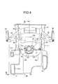
FIG. 4] FIG. 4 is a sectional view along line 4-4 inFIG. 3 . (first embodiment) - [
FIG. 5] FIG. 5 is a sectional view along line 5-5 inFIG. 4 in a state in which a swing arm is completely flexed. (first embodiment) - [
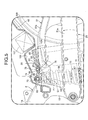
FIG. 6] FIG. 6 is a side view of a rear cushion unit from the same direction as inFIG. 2 . (first embodiment) - [
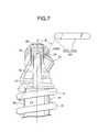
FIG. 7] FIG. 7 is a view in the direction of arrow 7 inFig. 6 . (first embodiment) - [
FIG. 8] FIG. 8 is a schematic sectional view for explaining the basic structure of the rear cushion unit. (first embodiment) - [
FIG. 9] FIG. 9 is a side view of an operation jig. (first embodiment) -
- 16
- Seat frame
- 24
- Swing arm
- 28
- Rear cushion unit
- 35
- Pillion step holder
- 36
- Pillion step
- 46
- Rear fender
- 47
- Side stand
- 51, 52
- Arm part
- 53
- Cross member part
- 61
- Damper cylinder
- 62
- Sub-tank
- 63
- Adjustment mechanism
- 64
- First operation element
- 65
- Second operation element
- 74
- Upper bracket, which is a bracket
- 76
- Housing tube part
- 77
- Opening part
- 78
- Operation face
- 98
- Inclined part
- 99
- Recess
- 100
- Housing recess
- 101
- Anti-lock brake control module
- 102
- Groove part
- 107
- Operation jig
- 107a
- Grip portion
- 107b
- Operation portion
- A
- Region
- F
- Vehicle body frame
- WR
- Rear wheel
- A mode for carrying out the present invention is explained by reference to the attached
FIG. 1 to FIG. 9 . In the explanation below, the vertical direction, the fore-and-aft direction, and the left-and-right direction are directions from the viewpoint of a rider. - First, in
FIG. 1 , a vehicle body frame F of this two-wheeled motor vehicle includes ahead pipe 13 that steerably supportshandlebars 12 and afront fork 11 axially supporting a front wheel WF, a pair of left and rightmain frames 14 that extend downward to the rear from thehead pipe 13, pivot frames 15 that are formed integrally with the respectivemain frames 14 so as to extend downward from the rear end of themain frames 14, and a pair of left and right seat frames 16 that are linked to the rear ends of themain frames 14 and extend upward to the rear. - An engine E is mounted on the vehicle body frame F so as to be disposed beneath the
main frames 14 between the front wheel WF and a rear wheel WR. Anoutput shaft 19 of a transmission (not illustrated) housed within acrankcase 18 of the engine E projects leftward from thecrankcase 18. Anendless chain 22 is wound around adrive sprocket 20 and a drivensprocket 21, thedrive sprocket 20 being fixedly provided on an end part, projecting from thecrankcase 18, of theoutput shaft 19, and the drivensprocket 21 being fixedly provided on anaxle 23 of the rear wheel WR. - Furthermore, a front end part of a
swing arm 24 is vertically swingably supported on the pivot frames 15 of the vehicle body frame F via asupport shaft 25, theswing arm 24 axially supporting via its rear end part theaxle 23 of the rear wheel WR. Achain cover 26 is mounted on theswing arm 24, thechain cover 26 covering from above part of a traveling portion of thechain 22 from the drivensprocket 21 toward thedrive sprocket 20 side. - Moreover, a linking
mechanism 27 is provided between theswing arm 24 and the pivot frames 15, and arear cushion unit 28 is provided between the linkingmechanism 27 and theswing arm 24. - A
fuel tank 29 positioned above an engine main body 17 is mounted on themain frames 14 of the vehicle body frame F. A rider'sseat 30 positioned to the rear of thefuel tank 29 and apillion seat 31 positioned to the rear of the rider'sseat 30 are supported by the seat frames 16. - Referring in addition to
FIG. 2 ,step holders 33 extending rearward are supported on the pivot frames 15 to the rear of thesupport shaft 25, and steps 34 are provided on a rear part of thestep holders 33, a rider seated on the rider'sseat 30 placing his/her feet on thesteps 34. Furthermore,pillion step holders 35 extending downward to the rear are each supported on intermediate parts in the fore-and-aft direction of the seat frames 16, and pillion steps 36 are provided on rear parts of thepillion step holders 35, a passenger seated on thepillion seat 31 placing his/her feet on the pillion steps 36. - Parts of the vehicle body frame F and the engine E are covered by a
vehicle body cover 37, which is made of a synthetic resin. Thisvehicle body cover 37 has anupper cowl 38 that covers thehead pipe 13 from the front, a pair of left and rightouter cowls 39 that are connectedly provided on theupper cowl 38 and cover a front part of the engine E from the side, a pair of left andright layer cowls 40 that are connectedly provided at lower edges of the respectiveouter cowls 39, a pair of left and right undercowls 41 that cover the engine E from beneath, atank cover 42 that covers thefuel tank 29, a pair of left and right knee covers 43 that are provided between thetank cover 42 and themain frames 14, and a pair of left andright tail cowls 44 that cover rear parts of the seat frames 16 from the side. - A
front fender 45 covering the front wheel WF from above is supported on thefront fork 11, and arear fender 46 disposed above theswing arm 24 and between the pair of left and right seat frames 16 is supported on a rear part of the vehicle body frame F. - Furthermore, a
side stand 47 and ashift pedal 48 are pivotably disposed on a lower part of theleft pivot frame 15 in the vehicle body frame F, the side stand 47 being capable of pivoting between a raised position (position shown inFIG. 2 ) in which the two-wheeled motor vehicle is tilted leftward and stopped and a stored position in which travel of the two-wheeled motor vehicle is possible, and theshift pedal 48 being for changing the gear position of the transmission within thecrankcase 18. - Referring in addition to
FIG. 3 to FIG. 5 , theswing arm 24 includes apivot pipe 50 that surrounds thesupport shaft 25 and is pivotably supported on thesupport shaft 25, aleft arm part 51 and aright arm part 52 that have front end parts joined to opposite end parts of thepivot pipe 50, are disposed on opposite left and right sides of the rear wheel WR, and extend in the fore-and-aft direction, and across member part 53 that is disposed between the rear wheel WR and thepivot pipe 50 and integrally links theleft arm part 51 and theright arm part 52. - The
left arm part 51 is formed from a left arm partmain body 51a that extends in the fore-and-aft direction along a straight line joining the axis of thesupport shaft 25 and the axis of theaxle 23 of the rear wheel WR, and asub arm 51b that joins a rear end part of the left arm partmain body 51a and a left upper part of thecross member part 53. Thecross member part 53 is formed so as to protrude above a front part upper face of the left arm partmain body 51 a, and thesub arm 51b is disposed above the left arm partmain body 51a so as to form, between itself and the left arm partmain body 51 a, anopening part 54 for travel of thechain 22. Thechain cover 26 is secured to the left arm partmain body 51a so as to extend through the openingpart 54. - The linking
mechanism 27, which is provided between theswing arm 24 and the pivot frames 15, includes a linkingarm 55 that forms a substantially triangular shape when viewed from the side and a linkingrod 56 that extends along substantially the fore-and-aft direction. Alower bracket 57 is provided on a lower face of a front part of the left arm partmain body 51a of theleft arm part 51 and a lower face of a front part of theright arm part 52 of theswing arm 24. An upper end part of the linkingarm 55 is linked to thelower bracket 57 via afirst linking shaft 58, which is parallel to thesupport shaft 25. Furthermore, a front end part of the linkingrod 56 is linked to a lower part of the pivot frames 15 in the vehicle body frame F via asecond linking shaft 59, which is parallel to thesupport shaft 25. A rear end part of the linkingrod 56 is linked to a rear end part of the linkingarm 55 via athird linking shaft 60, which is parallel to thesupport shaft 25. - Referring in addition to
FIG. 6 andFIG. 7 , therear cushion unit 28 includes adamper cylinder 61, a sub-tank 62 that is connected to thedamper cylinder 61 such that hydraulic oil can flow between itself and thedamper cylinder 61, and anadjustment mechanism 63 that is disposed between thedamper cylinder 61 and the sub-tank 62, theadjustment mechanism 63 having at least two operation elements, that is, first andsecond operation elements operation elements - The
damper cylinder 61 includes acylinder body 66 that extends in the vertical direction and apiston rod 67 that extends liquid-tightly through a lower end part of thecylinder body 66 and protrudes downward from thecylinder body 66. An upper mountingpart 68 is provided integrally with one end part (an upper end part in this embodiment) of thecylinder body 66. On the other hand, a lower mountingpart 69 is provided on an extremity part, that is, a lower end part, of thepiston rod 67. This lower mountingpart 69 is linked to a front end part of the linkingarm 55 in thelinking mechanism 27 via afourth linking shaft 70, which is parallel to thesupport shaft 25. - Furthermore, a
coil spring 73 surrounding thecylinder body 66 and thepiston rod 67 is provided in a compressed state between an upperspring receiving part 71 provided on an upper part of thecylinder body 66 and a lowerspring receiving part 72 provided on a lower part of thepiston rod 67, thecoil spring 73 applying an initial load to thedamper cylinder 61. - On the other hand, of the
left arm part 51 andright arm part 52 of theswing arm 24, portions positioned in front of thelower bracket 57 are provided integrally withupper brackets arm parts part 68 at the upper end of thecylinder body 66 is linked to theupper brackets 74 via afifth linking shaft 75, which is parallel to thesupport shaft 25. - Integrally and connectedly provided on the
cylinder body 66 is a bottomedhousing tube part 76 that houses theadjustment mechanism 63, which has in an upper end part anoperation face 78 having the first andsecond operation elements cylinder body 66. The sub-tank 62 extending in the fore-and-aft direction to the rear of thehousing tube part 76 is integrally and connectedly provided on thehousing tube part 76. That is, thecylinder body 66, thehousing tube part 76, and the sub-tank 62 are integrally and connectedly provided. Moreover, an upper half of the sub-tank 62 extending in the fore-and-aft direction is subjected to a buffing treatment as shown by dots inFIG. 2 ,FIG. 3 , andFIG. 5 toFIG. 7 . - The
housing tube part 76 is disposed so as to have an axis C2 that is tilted leftward only by an angle α (for example 30 degrees) relative to an axis C1 of thedamper cylinder 61 extending in the vertical direction such that theopening part 77 at the upper end faces obliquely outward. Theadjustment mechanism 63 is housed within thehousing tube part 76 so that theoperation face 78 having the first andsecond operation elements opening part 77, and theoperation face 78 is disposed so as to be inclined facing obliquely upwardly to the outside on the left-hand side. - Thus, the axis C2 of the
housing tube part 76 is disposed so as to be inclined leftward, that is, toward theside stand 47, which is disposed in the lower part of theleft pivot frame 15 of the vehicle body frame F, and the first andsecond operation elements operation face 78 disposed in theopening part 77 at the upper end of thehousing tube part 76 can thereby be operated from obliquely above on the outside on the left-hand side. - In
FIG. 8 , aninner tube 81 is coaxially inserted and fixed within thecylinder body 66, theinner tube 81 forming an annularouter flow path 82 between itself and the inner periphery of thecylinder body 66. Apiston 83 fixed to thepiston rod 67 is slidably fitted into theinner tube 81, and a piston-side oil chamber 84 and a rod-side oil chamber 85 separated from each other via thepiston 83 are formed within theinner tube 81. A plurality of communication holes 86 via which theouter flow path 82 communicates with the rod-side oil chamber 85 are provided in theinner tube 81. - The
adjustment mechanism 63 is formed by providing a compression-side dampingforce adjustment valve 91, a compression-side check valve 92, an extension-side dampingforce adjustment valve 93, and an extension-side check valve 94 in aholder 90. Theholder 90 is housed within thehousing tube part 76 while forming, between itself and thehousing tube part 76, an annular first extension-compressioncommon flow path 87 communicating with the piston-side oil chamber 84, a second extension-compressioncommon flow path 88 communicating with theouter flow path 82 connected to the rod-side oil chamber 85 via the communication holes 86, and an annular third extension-compressioncommon flow path 89 connected to the sub-tank 62. The compression-side dampingforce adjustment valve 91 is disposed between the first and third extension-compressioncommon flow paths side check valve 92 is disposed between the second and third extension-compressioncommon flow paths common flow path 89 toward the second extension-compressioncommon flow path 88. The extension-side dampingforce adjustment valve 93 is disposed between the second and third extension-compressioncommon flow paths side check valve 94 is disposed between the first and third extension-compressioncommon flow paths common flow path 89 toward the first extension-compressioncommon flow path 87. - The interior of the sub-tank 62 is divided into an
air chamber 96 and an oil-retainingchamber 97 by means of abladder 95, and the third extension-compressioncommon flow path 89 of theadjustment mechanism 63 communicates with the oil-retainingchamber 97. - In such a
rear cushion unit 28, during the compression-side stroke of thedamper cylinder 61, hydraulic oil flows as shown by the solid line arrows inFIG. 8 . Due to hydraulic oil of the piston-side oil chamber 84, whose oil pressure has increased, flowing from the first extension-compressioncommon flow path 87 of theadjustment mechanism 63 to the third extension-compressioncommon flow path 89 via the compression-side dampingforce adjustment valve 91, a compression-side damping force is generated. Hydraulic oil from the compression-side dampingforce adjustment valve 91 is divided into two by means of the third extension-compressioncommon flow path 89, some hydraulic oil flows from the compression-side check valve 92 to the rod-side oil chamber 85 via the second extension-compressioncommon flow path 88, theouter flow path 82, and the communication holes 86, and the remaining hydraulic oil flows into the oil-retainingchamber 97 within the sub-tank 62. - Furthermore, during the extension side stroke of the
damper cylinder 61, hydraulic oil flows as shown by the chain line arrows inFIG. 8 . Due to hydraulic oil of the rod-side oil chamber 85, whose oil pressure has increased, flowing to the second extension-compressioncommon flow path 88 of theadjustment mechanism 63 via the communication holes 86 and theouter flow path 82 and from the second extension-compressioncommon flow path 88 to the third extension-compressioncommon flow path 89 via the extension-side dampingforce adjustment valve 93, an extension-side damping force is generated. In the third extension-compressioncommon flow path 89, hydraulic oil from the extension-side dampingforce adjustment valve 93 and hydraulic oil from the oil-retainingchamber 97 of the sub-tank 62 are combined and flow from the extension-side check valve 94 to the piston-side oil chamber 84 via the first extension-compressioncommon flow path 87. - The compression-side damping
force adjustment valve 91 and the extension-side dampingforce adjustment valve 93 in theadjustment mechanism 63 are formed from damping force-generatingvalves variable orifices operation elements first operation element 64 can adjust the degree of opening of thevariable orifice 91b of the compression-side dampingforce adjustment valve 91, that is, the damping force on the compression side of thedamper cylinder 61. Thesecond operation element 65 can adjust the degree of opening of thevariable orifice 93b of the extension-side dampingforce adjustment valve 93, that is, the damping force on the extension side of thedamper cylinder 61. - Referring again to
FIG. 2 , the first andsecond operation elements adjustment mechanism 63 are disposed so as to face a region A bounded by theleft seat frame 16 forming part of the vehicle body frame F, thepillion step holder 35 mounted on theseat frame 16, and theswing arm 24 when the two-wheeled motor vehicle is viewed from the left-hand side, and theoperation face 78 is disposed so as to be inclined obliquely upward to the outside on the left-hand side, therefore making it possible to operate the first andsecond operation elements - Furthermore, as clearly shown in
FIG. 2 andFIG. 5 , the first andsecond operation elements upper bracket 74 provided integrally with thearm parts swing arm 24, and beneath the upper end of theupper bracket 74. - Moreover, as shown in
FIG. 5 , aninclined part 98 is formed at the upper end of thesub arm 51b in theleft arm part 51, which is one of the pair of left andright arm parts swing arm 24, in a portion positioned to the rear of theupper bracket 74, theinclined part 98 being inclined upwardly to the rear from the lower end of theupper bracket 74. The first andsecond operation elements recess 99 formed between the lower part of theupper bracket 74 and theinclined part 98 when viewed from the side. - The
rear fender 46 is disposed above theswing arm 24 and between the pair of left and right seat frames 16, and ahousing recess 100 is formed in a lower face of therear fender 46 as shown inFIG. 5 , thehousing recess 100 housing the upper part of thedamper cylinder 61, the upper part of theadjustment mechanism 63 including the first andsecond operation elements swing arm 24 is completely flexed. - Furthermore, an anti-lock
brake control module 101 is disposed within therear fender 46 to the rear of thehousing recess 100. - A
groove part 102 extending in the fore-and-aft direction is formed in an upper face of a central part in the vehicle width direction of thecross member part 53 provided integrally with theswing arm 24. When viewed from the rear as shown inFIG. 4 , part of the sub-tank 62, an upper end part of thedamper cylinder 61, and an upper end part of theadjustment mechanism 63 including the first andsecond operation elements groove part 102. - Furthermore, a
cover 104 having agroove part 103 communicating with thegroove part 102 is secured to a rear part of thecross member part 53 by means of ascrew member 105 so as to cover, from beneath, a portion of the sub-tank 62 that juts out of thecross member part 53 to the rear. - In
FIG. 9 , anoperation jig 107 prepared for when operating the first andsecond operation elements grip portion 107a for an operator to grip and anoperation portion 107b connected to thegrip portion 107a through an angle so as to exert an operating force on the first andsecond operation elements operation portion 107b can engage with latchinggrooves FIG. 6 ) provided in the first andsecond operation elements - The operation of this embodiment is now explained. Since the
cylinder body 66 of thedamper cylinder 61 in therear cushion unit 28, the bottomedhousing tube part 76 housing theadjustment mechanism 63, and the sub-tank 62 are integrally and connectedly provided, it is unnecessary to employ a mounting member exclusively used for mounting theadjustment mechanism 63 on the vehicle body, and therear cushion unit 28 can be disposed in a compact manner. - Furthermore, the
pillion step holders 35 having provided thereon the pillion steps 36 for a passenger to place his/her feet on are mounted on the seat frames 16 disposed above theswing arm 24, the first andsecond operation elements adjustment mechanism 63 are disposed so as to face the region A bounded by theseat frame 16, thepillion step holder 35, and theswing arm 24 when viewed from the left-hand side of the two-wheeled motor vehicle, and theoperation face 78 having the first andsecond operation elements second operation elements adjustment mechanism 63 with good space efficiency while enabling it to be easily operated from the outside. - Moreover, the
adjustment mechanism 63 has at least thefirst operation element 64 for adjusting the damping force on the compression side of thedamper cylinder 61 and thesecond operation element 64 for adjusting the damping force on the extension side of thedamper cylinder 61, and theseoperation elements adjustment mechanism 63. - Furthermore, the
swing arm 24 has the pair of left andright arm parts upper brackets 74 for mounting the upper end of thedamper cylinder 61 are provided integrally with the left andright arm parts arm parts second operation elements upper brackets 74 and beneath the upper end of theupper brackets 74, therefore making it possible to easily ensure that there is space for disposing the first andsecond operation elements swing arm 24 and thus enabling the first andsecond operation elements - Moreover, the
inclined part 98, which is inclined upwardly to the rear from the lower end of theupper bracket 74, is formed at the upper end of thesub arm 51b of theleft arm part 51, which is one of the left andright arm parts upper brackets 74, and the first andsecond operation elements recess 99 formed between the lower part of theupper bracket 74 and theinclined part 98 when viewed from the side, therefore making it possible to dispose the first andsecond operation elements swing arm 24. - The
rear fender 46 is disposed above theswing arm 24 and between the pair of left and right seat frames 16, and thehousing recess 100 housing the upper part of thedamper cylinder 61, the first andsecond operation elements swing arm 24 is completely flexed is formed in the lower face of therear fender 46, therefore making it possible to disposerear fender 46 and therear cushion unit 28 with good space efficiency relative to each other while ensuring the function of therear fender 46 and thus protecting therear cushion unit 28. - Moreover, since the anti-lock
brake control module 101 is disposed within therear fender 46 to the rear of thehousing recess 100, it is possible to dispose the anti-lockbrake control module 101 with good efficiency and good weight balance at a position where it does not interfere with therear cushion unit 28 when completely flexed, while exploiting placement of therear cushion unit 28 with good space efficiency. - The
housing tube part 76 housing theadjustment mechanism 63 having theoperation face 78 on the upper end part is disposed so as to have the axis C2 tilted leftward relative to the axis C1 of thedamper cylinder 61 extending in the vertical direction so as to make theopening part 77 at the upper end face obliquely outward, and theadjustment mechanism 63 is housed within thehousing tube part 76 so that theoperation face 78 having the first andsecond operation elements opening part 77, therefore making it possible to operate the first andsecond operation elements rear cushion unit 28 in the vehicle width direction. - Furthermore, since the side stand 47 is supported on the left side of the vehicle body frame F, and the first and
second operation elements second operation elements side stand 47. - The
swing arm 24 integrally has the pair of left andright arm parts cross member part 53 linking the front parts of thearm parts damper cylinder 61, and the first andsecond operation elements groove part 102 that is formed in the upper face of the central part, in the vehicle width direction, of thecross member part 53 and extends in the fore-and-aft direction, therefore making it possible to dispose therear cushion unit 28 in a compact manner so as to protect it by means of theswing arm 24 while ensuring the stiffness of theswing arm 24. - Moreover, the
operation jig 107 for operating the first andsecond operation elements grip portion 107a for an operator to grip and theoperation portion 107b connected to thegrip portion 107a through an angle so as to exert an operating force on the first andsecond operation elements second operation elements operation portion 107b in a state in which thegrip portion 107a is gripped substantially horizontally as shown inFIG. 7 , thereby making easier the operation of the first andsecond operation elements - Moreover, since an upper half of the sub-tank 62 disposed so as to extend in the fore-and-aft direction is subjected to a buffing treatment, it is possible to improve the appearance of a portion, exposed to the outside, of the sub-tank 62 while enhancing the cost efficiency compared with a case in which the entire outer periphery is subjected to a buffing treatment.
- An embodiment of the present invention is explained above, but the present invention is not limited to the embodiment above and may be modified in a variety of ways as long as the modifications do not depart from the scope thereof as defined in the appended claims.
Claims (11)
- A two-wheeled motor vehicle in which a rear cushion unit (28) is provided between a vehicle body frame (F) and a swing arm (24), the rear cushion unit (28) comprising
a damper cylinder (61) having one end part linked to the swing arm (24) that axially supports a rear wheel (WR) by a rear end part and is swingably supported on the vehicle body frame (F),
a sub-tank (62) that is connected to the damper cylinder (61) so as to enable hydraulic oil to flow between the sub-tank (62) and the damper cylinder (61), and
an adjustment mechanism (63) that has an operation element (64, 65) and is disposed between the damper cylinder (61) and the sub-tank (62) so as to be capable of adjusting a damping force in response to an operation of the operation element (64, 65) wherein a pillion step holder (35) is mounted on a seat frame (16) that forms part of the vehicle body frame (F) and is disposed above the swing arm (24) and
a pillion step (36) for a foot of a passenger to be placed is provided on the pillion step holder (35),
characterized in
that a cylinder body (66) of the damper cylinder (61), a bottomed housing tube part (76) housing the adjustment mechanism (63) having on an upper end part an operation face (78) on which the operation element (64, 65) is disposed, and the sub-tank (62) are integrally and connectedly provided, and the operation face (78) is disposed so as to be inclined obliquely upward so that the operation element (64, 65) that faces a region (A) bounded by the seat frame (16), the pillion step holder (35) and the swing arm (24) when viewed from the side can be operated from obliquely above on the outside. - The two-wheeled motor vehicle according to Claim 1,
wherein the adjustment mechanism (63) comprises at least a first operation element (64) for adjusting a damping force on the compression side of the damper cylinder (61) and a second operation element (65) for adjusting a damping force on the extension side of the damper cylinder (61), and the operation elements (64, 65) are disposed so as to face the region (A) and be operable from obliquely above on the outside. - The two-wheeled motor vehicle according to Claim 1,
wherein the swing arm (24) comprises a pair of arm parts (51, 52) that are disposed on opposite left and right sides of the rear wheel (WR) and are linked to each other, a bracket (74) is provided integrally with the arm parts (51, 52) so as to protrude above the arm parts (51, 52) when viewed from the side, an upper end of the damper cylinder (61) being mounted on the bracket (74), and the operation element (64, 65) is disposed to the rear of the bracket (74) and below the upper end of the bracket (74). - The two-wheeled motor vehicle according to Claim 1,
wherein an inclined part (98) that is inclined upwardly to the rear from a lower end of the bracket (74) is formed at an upper end of one of the two arm parts (51, 52) in a portion positioned to the rear of the bracket (74), and the operation element (64, 65) is disposed so as to face a recess (99) formed between a lower part of the bracket (74) and the inclined part (98) when viewed from the side. - The two-wheeled motor vehicle according to Claim 1,
wherein a rear fender (46) is disposed above the swing arm (24) and between a pair of left and right seat frames (16), and a housing recess (100) is formed in a lower face of the rear fender (46), the housing recess (100) being configured to house an upper part of the damper cylinder (61), the operation element (64, 65) and the sub-tank (62) when the swing arm (24) is completely flexed. - The two-wheeled motor vehicle according to Claim 5,
wherein an anti-lock brake control module (101) is disposed within the rear fender (46) to the rear of the housing recess (100). - The two-wheeled motor vehicle according to Claim 1,
wherein the housing tube part (76) is disposed so as to have an axis inclined relative to an axis of the damper cylinder (61), which extends in the vertical direction, while an opening part (77) at an upper end of the housing tube part (76) faces obliquely outward, and the adjustment mechanism (63) is housed within the housing tube part (76) so that the operation face (78) is positioned in the opening part (77), the operation element (64, 65) being disposed on the operation face (78). - The two-wheeled motor vehicle according to Claim 1,
wherein a side stand (47) is supported on one of right and left sides of the vehicle body frame (F), and the operation element (64, 65) is disposed on the side stand side in an inclined manner. - The two-wheeled motor vehicle according to Claim 1,
wherein the swing arm (24) integrally comprises a pair of arm parts (51, 52) disposed on opposite left and right sides of the rear wheel (WR) and a cross member part (53) linking front parts of the arm parts (51, 52), a groove part (102) extending in the fore-and-aft direction is formed in an upper face of a central part of the cross member part (53) in the vehicle width direction, and part of the sub-tank (62), an upper end part of the damper cylinder (61) and the operation element (64, 65) are disposed within the width of the groove part (102) when viewed from the rear. - The two-wheeled motor vehicle according to Claim 1,
wherein the operation element (64, 65) is configured to be operated by an operation jig (107), and
the operation jig (107) comprises a grip portion (107a) for an operator to grip and an operation portion (107b) connected to the grip portion (107a) at an angle,
wherein the operation portion (107b) is configured to exert an operating force on the operation element (64, 65). - The two-wheeled motor vehicle according to Claim 1,
wherein an upper half of the sub-tank (62) disposed so as to extend in the fore-and-aft direction is subjected to a buffing treatment.
Applications Claiming Priority (2)
| Application Number | Priority Date | Filing Date | Title |
|---|---|---|---|
| JP2011122832 | 2011-05-31 | ||
| PCT/JP2012/063486 WO2012165332A1 (en) | 2011-05-31 | 2012-05-25 | Two-wheeled motor vehicle |
Publications (3)
| Publication Number | Publication Date |
|---|---|
| EP2716536A1 EP2716536A1 (en) | 2014-04-09 |
| EP2716536A4 EP2716536A4 (en) | 2014-11-26 |
| EP2716536B1 true EP2716536B1 (en) | 2015-12-30 |
Family
ID=47259189
Family Applications (1)
| Application Number | Title | Priority Date | Filing Date |
|---|---|---|---|
| EP12793627.6A Not-in-force EP2716536B1 (en) | 2011-05-31 | 2012-05-25 | Two-wheeled motor vehicle |
Country Status (5)
| Country | Link |
|---|---|
| US (1) | US8955633B2 (en) |
| EP (1) | EP2716536B1 (en) |
| JP (1) | JP5638133B2 (en) |
| BR (1) | BR112013029734B1 (en) |
| WO (1) | WO2012165332A1 (en) |
Cited By (1)
| Publication number | Priority date | Publication date | Assignee | Title |
|---|---|---|---|---|
| CN109552604A (en) * | 2018-11-13 | 2019-04-02 | 中国直升机设计研究所 | A kind of shimmy-damper having both alignment function |
Families Citing this family (36)
| Publication number | Priority date | Publication date | Assignee | Title |
|---|---|---|---|---|
| US8991840B2 (en) * | 2013-03-14 | 2015-03-31 | Oshkosh Defense, Llc | Load dependent damper for a vehicle suspension system |
| JP6136536B2 (en) * | 2013-04-26 | 2017-05-31 | スズキ株式会社 | Motorcycle swing arm |
| JP6134586B2 (en) * | 2013-06-06 | 2017-05-24 | 本田技研工業株式会社 | Saddle riding vehicle |
| US9481426B2 (en) * | 2013-11-08 | 2016-11-01 | Suzuki Motor Corporation | Swing arm |
| US9168972B2 (en) * | 2014-01-02 | 2015-10-27 | Taiwan Hodaka Industrial Co., Ltd. | Control device for the rear shock absorber of a bicycle |
| DE102015104494A1 (en) * | 2015-03-25 | 2016-09-29 | Thyssenkrupp Ag | Vibration damper with shortened overall length |
| DE102015104489B4 (en) * | 2015-03-25 | 2023-03-23 | Thyssenkrupp Ag | Vibration damper with reduced overall length |
| JP1568692S (en) * | 2016-05-27 | 2017-02-06 | ||
| JP1568028S (en) * | 2016-07-29 | 2017-01-30 | ||
| JP1568649S (en) * | 2016-09-02 | 2017-02-06 | ||
| WO2018164998A1 (en) | 2017-03-10 | 2018-09-13 | Indian Motorcycle International, LLC | Two-wheeled vehicle |
| USD860059S1 (en) * | 2017-08-23 | 2019-09-17 | Bayerische Motoren Werke Aktiengesellschaft | Motorcycle, toy, and/or replicas thereof |
| TWD195925S (en) * | 2017-08-30 | 2019-02-11 | 光陽工業股份有限公司 | Car body (145) |
| USD847031S1 (en) * | 2017-09-28 | 2019-04-30 | Kawasaki Jukogyo Kabushiki Kaisha | Motorcycle |
| USD849602S1 (en) * | 2017-09-29 | 2019-05-28 | Kawasaki Jukogyo Kabushiki Kaisha | Motorcycle |
| JP1608421S (en) * | 2018-02-28 | 2018-10-29 | ||
| JP1623372S (en) * | 2018-04-26 | 2020-01-27 | ||
| USD875615S1 (en) * | 2018-05-14 | 2020-02-18 | Bayerische Motoren Werke Aktiengesellschaft | Motorcycle, toy, and/or replicas thereof |
| USD875616S1 (en) * | 2018-05-14 | 2020-02-18 | Bayerische Motoren Werke Aktiengesellschaft | Motorcycle, toy, and/or replicas thereof |
| JP1622355S (en) * | 2018-05-30 | 2019-01-21 | ||
| JP1621512S (en) * | 2018-05-31 | 2019-01-07 | ||
| JP1626746S (en) * | 2018-08-09 | 2019-03-18 | ||
| USD911879S1 (en) * | 2018-09-10 | 2021-03-02 | Indian Motorcycle International, LLC | Motorcycle |
| US11077910B2 (en) | 2018-09-28 | 2021-08-03 | Indian Motorcycle International, LLC | Two-wheeled vehicle |
| CA190940S (en) * | 2018-10-10 | 2021-02-01 | Arc Vehicle Ltd | Motorcycle |
| USD902083S1 (en) * | 2018-10-29 | 2020-11-17 | Piaggio & C. S.P.A. | Motorcycle |
| USD902787S1 (en) * | 2018-11-02 | 2020-11-24 | Piaggio & C. S.P.A. | Motor scooter |
| USD911223S1 (en) * | 2019-01-11 | 2021-02-23 | Yamaha Hatsudoki Kabushiki Kaisha | Motorcycle |
| JP7354041B2 (en) * | 2020-03-27 | 2023-10-02 | 本田技研工業株式会社 | cushion support structure |
| USD940009S1 (en) * | 2020-04-09 | 2022-01-04 | Piaggio & C. S.P.A. | Motorcycle |
| USD958700S1 (en) * | 2020-04-28 | 2022-07-26 | Bayerische Motoren Werke Aktiengesellschaft | Motorcycle, toy, and/or replicas thereof |
| JP1675700S (en) * | 2020-08-31 | 2021-01-04 | ||
| US20220234679A1 (en) * | 2021-01-28 | 2022-07-28 | Fox Factory, Inc. | Damper with an annular base valve flow system |
| JP1703391S (en) * | 2021-04-30 | 2021-12-27 | ||
| USD986776S1 (en) * | 2021-10-08 | 2023-05-23 | Suzuki Motor Corporation | Motorcycle |
| USD999678S1 (en) * | 2021-11-03 | 2023-09-26 | Vmoto Europe B.V. | Motorcycle |
Family Cites Families (20)
| Publication number | Priority date | Publication date | Assignee | Title |
|---|---|---|---|---|
| JPS5919492A (en) | 1982-07-23 | 1984-01-31 | Canon Inc | Image pickup device |
| JPS5919492U (en) | 1982-07-30 | 1984-02-06 | 本田技研工業株式会社 | Rear suspension sub-tank mounting structure |
| NL8600211A (en) * | 1986-01-30 | 1987-08-17 | White Power Prod Bv | HYDRAULIC SHOCK ABSORBER. |
| JPH07208529A (en) * | 1994-01-13 | 1995-08-11 | Suzuki Motor Corp | Installation structure for suspension stroke sensor for motorcycle |
| SE9602507L (en) * | 1996-06-25 | 1997-12-26 | Oehlins Racing Ab | Shock |
| JP4138176B2 (en) * | 1999-09-01 | 2008-08-20 | 本田技研工業株式会社 | Motorcycle |
| JP3768788B2 (en) * | 2000-09-05 | 2006-04-19 | 本田技研工業株式会社 | Vehicle swing arm suspension system |
| US7472772B2 (en) * | 2003-02-20 | 2009-01-06 | Honda Motor Co., Ltd. | Structure for installing rear cushion |
| JP4130377B2 (en) * | 2003-04-04 | 2008-08-06 | 本田技研工業株式会社 | Vehicle swing arm suspension system |
| EP1685480B1 (en) * | 2003-08-12 | 2017-05-31 | Graeme K. Robertson | Shock absorber assembly |
| JP4130395B2 (en) * | 2003-09-09 | 2008-08-06 | 本田技研工業株式会社 | Swing arm suspension |
| JP4394933B2 (en) * | 2003-12-02 | 2010-01-06 | 株式会社ショーワ | Suspension devices such as motorcycles |
| JP4921801B2 (en) * | 2006-02-01 | 2012-04-25 | 本田技研工業株式会社 | Rear wheel suspension system for motorcycles |
| JP4928964B2 (en) * | 2007-01-30 | 2012-05-09 | 本田技研工業株式会社 | Vehicle swing arm suspension system |
| JP5001092B2 (en) * | 2007-08-27 | 2012-08-15 | 本田技研工業株式会社 | Motorcycle |
| JP4705938B2 (en) * | 2007-08-30 | 2011-06-22 | 本田技研工業株式会社 | Saddle-type vehicle with rear master cylinder |
| JP5192861B2 (en) * | 2008-03-18 | 2013-05-08 | 本田技研工業株式会社 | Rear structure of motorcycle |
| JP5190298B2 (en) * | 2008-05-21 | 2013-04-24 | ヤマハ発動機株式会社 | Cushion unit and motorcycle equipped with the same |
| JP5328448B2 (en) | 2009-03-30 | 2013-10-30 | 本田技研工業株式会社 | Motorcycle |
| JP5451287B2 (en) * | 2009-09-25 | 2014-03-26 | 本田技研工業株式会社 | Cylinder head cover structure for small vehicles |
-
2012
- 2012-05-25 EP EP12793627.6A patent/EP2716536B1/en not_active Not-in-force
- 2012-05-25 JP JP2013518054A patent/JP5638133B2/en active Active
- 2012-05-25 WO PCT/JP2012/063486 patent/WO2012165332A1/en active Application Filing
- 2012-05-25 BR BR112013029734-4A patent/BR112013029734B1/en not_active IP Right Cessation
- 2012-05-25 US US14/122,358 patent/US8955633B2/en active Active
Cited By (1)
| Publication number | Priority date | Publication date | Assignee | Title |
|---|---|---|---|---|
| CN109552604A (en) * | 2018-11-13 | 2019-04-02 | 中国直升机设计研究所 | A kind of shimmy-damper having both alignment function |
Also Published As
| Publication number | Publication date |
|---|---|
| WO2012165332A1 (en) | 2012-12-06 |
| BR112013029734A2 (en) | 2017-01-24 |
| EP2716536A1 (en) | 2014-04-09 |
| JP5638133B2 (en) | 2014-12-10 |
| EP2716536A4 (en) | 2014-11-26 |
| US8955633B2 (en) | 2015-02-17 |
| JPWO2012165332A1 (en) | 2015-02-23 |
| US20140084565A1 (en) | 2014-03-27 |
| BR112013029734B1 (en) | 2021-01-26 |
Similar Documents
| Publication | Publication Date | Title |
|---|---|---|
| EP2716536B1 (en) | Two-wheeled motor vehicle | |
| CN110015373B (en) | ABS configuration structure of straddle type vehicle | |
| US7543672B2 (en) | Straddle-type wheeled vehicle and frame thereof | |
| ES2593637T3 (en) | Astride brake device for astride | |
| US20140091539A1 (en) | Electric suspension device and motorcycle | |
| US20160297498A1 (en) | Bicycle with suspension | |
| US20140361512A1 (en) | Saddle-ride type vehicle | |
| JP2007112154A (en) | Saddle riding type vehicle and steering damper used for it | |
| EP1514787B1 (en) | Swing arm suspension | |
| JP6256837B2 (en) | Steering structure for saddle-ride type vehicles | |
| EP2196384B1 (en) | Straddle-type wheeled vehicle and frame thereof | |
| US8813894B1 (en) | Motorcycle | |
| JP7163392B2 (en) | straddle-type vehicle | |
| US8439380B2 (en) | Front structure of saddle type vehicle | |
| JP2005231603A (en) | Suspension for two-wheeler | |
| EP2868561B1 (en) | Straddle-type vehicle | |
| CN109720328B (en) | Saddle-ride type vehicle | |
| JP2018020655A (en) | Saddle-riding type vehicle | |
| WO2020100838A1 (en) | Saddled vehicle | |
| US11535336B2 (en) | Saddle riding vehicle | |
| JP6890627B2 (en) | Saddle-type vehicle | |
| CN111655571B (en) | Saddle-ride type vehicle | |
| WO2020031455A1 (en) | Saddle riding type vehicle | |
| US20200255083A1 (en) | Brake piping structure for saddled vehicles | |
| EP3381784A1 (en) | Steering damper apparatus for saddle-ride type vehicle |
Legal Events
| Date | Code | Title | Description |
|---|---|---|---|
| PUAI | Public reference made under article 153(3) epc to a published international application that has entered the european phase |
Free format text: ORIGINAL CODE: 0009012 |
|
| 17P | Request for examination filed |
Effective date: 20131119 |
|
| AK | Designated contracting states |
Kind code of ref document: A1 Designated state(s): AL AT BE BG CH CY CZ DE DK EE ES FI FR GB GR HR HU IE IS IT LI LT LU LV MC MK MT NL NO PL PT RO RS SE SI SK SM TR |
|
| DAX | Request for extension of the european patent (deleted) | ||
| A4 | Supplementary search report drawn up and despatched |
Effective date: 20141024 |
|
| RIC1 | Information provided on ipc code assigned before grant |
Ipc: F16F 9/32 20060101ALI20141020BHEP Ipc: B62J 15/00 20060101ALI20141020BHEP Ipc: B62K 25/20 20060101AFI20141020BHEP |
|
| REG | Reference to a national code |
Ref country code: DE Ref legal event code: R079 Ref document number: 602012013512 Country of ref document: DE Free format text: PREVIOUS MAIN CLASS: B62K0025200000 Ipc: B62K0025280000 |
|
| GRAP | Despatch of communication of intention to grant a patent |
Free format text: ORIGINAL CODE: EPIDOSNIGR1 |
|
| RIC1 | Information provided on ipc code assigned before grant |
Ipc: B62K 25/28 20060101AFI20150624BHEP Ipc: F16F 9/06 20060101ALI20150624BHEP |
|
| INTG | Intention to grant announced |
Effective date: 20150720 |
|
| GRAS | Grant fee paid |
Free format text: ORIGINAL CODE: EPIDOSNIGR3 |
|
| GRAA | (expected) grant |
Free format text: ORIGINAL CODE: 0009210 |
|
| AK | Designated contracting states |
Kind code of ref document: B1 Designated state(s): AL AT BE BG CH CY CZ DE DK EE ES FI FR GB GR HR HU IE IS IT LI LT LU LV MC MK MT NL NO PL PT RO RS SE SI SK SM TR |
|
| REG | Reference to a national code |
Ref country code: GB Ref legal event code: FG4D |
|
| REG | Reference to a national code |
Ref country code: CH Ref legal event code: EP |
|
| REG | Reference to a national code |
Ref country code: AT Ref legal event code: REF Ref document number: 767319 Country of ref document: AT Kind code of ref document: T Effective date: 20160115 |
|
| REG | Reference to a national code |
Ref country code: IE Ref legal event code: FG4D |
|
| REG | Reference to a national code |
Ref country code: DE Ref legal event code: R096 Ref document number: 602012013512 Country of ref document: DE |
|
| REG | Reference to a national code |
Ref country code: LT Ref legal event code: MG4D |
|
| PG25 | Lapsed in a contracting state [announced via postgrant information from national office to epo] |
Ref country code: LT Free format text: LAPSE BECAUSE OF FAILURE TO SUBMIT A TRANSLATION OF THE DESCRIPTION OR TO PAY THE FEE WITHIN THE PRESCRIBED TIME-LIMIT Effective date: 20151230 Ref country code: NO Free format text: LAPSE BECAUSE OF FAILURE TO SUBMIT A TRANSLATION OF THE DESCRIPTION OR TO PAY THE FEE WITHIN THE PRESCRIBED TIME-LIMIT Effective date: 20160330 Ref country code: HR Free format text: LAPSE BECAUSE OF FAILURE TO SUBMIT A TRANSLATION OF THE DESCRIPTION OR TO PAY THE FEE WITHIN THE PRESCRIBED TIME-LIMIT Effective date: 20151230 |
|
| REG | Reference to a national code |
Ref country code: NL Ref legal event code: MP Effective date: 20151230 |
|
| REG | Reference to a national code |
Ref country code: AT Ref legal event code: MK05 Ref document number: 767319 Country of ref document: AT Kind code of ref document: T Effective date: 20151230 |
|
| REG | Reference to a national code |
Ref country code: FR Ref legal event code: PLFP Year of fee payment: 5 |
|
| PG25 | Lapsed in a contracting state [announced via postgrant information from national office to epo] |
Ref country code: SE Free format text: LAPSE BECAUSE OF FAILURE TO SUBMIT A TRANSLATION OF THE DESCRIPTION OR TO PAY THE FEE WITHIN THE PRESCRIBED TIME-LIMIT Effective date: 20151230 Ref country code: LV Free format text: LAPSE BECAUSE OF FAILURE TO SUBMIT A TRANSLATION OF THE DESCRIPTION OR TO PAY THE FEE WITHIN THE PRESCRIBED TIME-LIMIT Effective date: 20151230 Ref country code: RS Free format text: LAPSE BECAUSE OF FAILURE TO SUBMIT A TRANSLATION OF THE DESCRIPTION OR TO PAY THE FEE WITHIN THE PRESCRIBED TIME-LIMIT Effective date: 20151230 Ref country code: GR Free format text: LAPSE BECAUSE OF FAILURE TO SUBMIT A TRANSLATION OF THE DESCRIPTION OR TO PAY THE FEE WITHIN THE PRESCRIBED TIME-LIMIT Effective date: 20160331 Ref country code: FI Free format text: LAPSE BECAUSE OF FAILURE TO SUBMIT A TRANSLATION OF THE DESCRIPTION OR TO PAY THE FEE WITHIN THE PRESCRIBED TIME-LIMIT Effective date: 20151230 |
|
| PG25 | Lapsed in a contracting state [announced via postgrant information from national office to epo] |
Ref country code: NL Free format text: LAPSE BECAUSE OF FAILURE TO SUBMIT A TRANSLATION OF THE DESCRIPTION OR TO PAY THE FEE WITHIN THE PRESCRIBED TIME-LIMIT Effective date: 20151230 |
|
| PG25 | Lapsed in a contracting state [announced via postgrant information from national office to epo] |
Ref country code: CZ Free format text: LAPSE BECAUSE OF FAILURE TO SUBMIT A TRANSLATION OF THE DESCRIPTION OR TO PAY THE FEE WITHIN THE PRESCRIBED TIME-LIMIT Effective date: 20151230 Ref country code: ES Free format text: LAPSE BECAUSE OF FAILURE TO SUBMIT A TRANSLATION OF THE DESCRIPTION OR TO PAY THE FEE WITHIN THE PRESCRIBED TIME-LIMIT Effective date: 20151230 |
|
| PG25 | Lapsed in a contracting state [announced via postgrant information from national office to epo] |
Ref country code: EE Free format text: LAPSE BECAUSE OF FAILURE TO SUBMIT A TRANSLATION OF THE DESCRIPTION OR TO PAY THE FEE WITHIN THE PRESCRIBED TIME-LIMIT Effective date: 20151230 Ref country code: RO Free format text: LAPSE BECAUSE OF FAILURE TO SUBMIT A TRANSLATION OF THE DESCRIPTION OR TO PAY THE FEE WITHIN THE PRESCRIBED TIME-LIMIT Effective date: 20151230 Ref country code: SK Free format text: LAPSE BECAUSE OF FAILURE TO SUBMIT A TRANSLATION OF THE DESCRIPTION OR TO PAY THE FEE WITHIN THE PRESCRIBED TIME-LIMIT Effective date: 20151230 Ref country code: IS Free format text: LAPSE BECAUSE OF FAILURE TO SUBMIT A TRANSLATION OF THE DESCRIPTION OR TO PAY THE FEE WITHIN THE PRESCRIBED TIME-LIMIT Effective date: 20160430 Ref country code: SM Free format text: LAPSE BECAUSE OF FAILURE TO SUBMIT A TRANSLATION OF THE DESCRIPTION OR TO PAY THE FEE WITHIN THE PRESCRIBED TIME-LIMIT Effective date: 20151230 Ref country code: PL Free format text: LAPSE BECAUSE OF FAILURE TO SUBMIT A TRANSLATION OF THE DESCRIPTION OR TO PAY THE FEE WITHIN THE PRESCRIBED TIME-LIMIT Effective date: 20151230 Ref country code: PT Free format text: LAPSE BECAUSE OF FAILURE TO SUBMIT A TRANSLATION OF THE DESCRIPTION OR TO PAY THE FEE WITHIN THE PRESCRIBED TIME-LIMIT Effective date: 20160502 Ref country code: BE Free format text: LAPSE BECAUSE OF NON-PAYMENT OF DUE FEES Effective date: 20160531 Ref country code: AT Free format text: LAPSE BECAUSE OF FAILURE TO SUBMIT A TRANSLATION OF THE DESCRIPTION OR TO PAY THE FEE WITHIN THE PRESCRIBED TIME-LIMIT Effective date: 20151230 |
|
| REG | Reference to a national code |
Ref country code: DE Ref legal event code: R097 Ref document number: 602012013512 Country of ref document: DE |
|
| PG25 | Lapsed in a contracting state [announced via postgrant information from national office to epo] |
Ref country code: DK Free format text: LAPSE BECAUSE OF FAILURE TO SUBMIT A TRANSLATION OF THE DESCRIPTION OR TO PAY THE FEE WITHIN THE PRESCRIBED TIME-LIMIT Effective date: 20151230 |
|
| PLBE | No opposition filed within time limit |
Free format text: ORIGINAL CODE: 0009261 |
|
| STAA | Information on the status of an ep patent application or granted ep patent |
Free format text: STATUS: NO OPPOSITION FILED WITHIN TIME LIMIT |
|
| 26N | No opposition filed |
Effective date: 20161003 |
|
| PG25 | Lapsed in a contracting state [announced via postgrant information from national office to epo] |
Ref country code: LU Free format text: LAPSE BECAUSE OF FAILURE TO SUBMIT A TRANSLATION OF THE DESCRIPTION OR TO PAY THE FEE WITHIN THE PRESCRIBED TIME-LIMIT Effective date: 20160525 Ref country code: BE Free format text: LAPSE BECAUSE OF FAILURE TO SUBMIT A TRANSLATION OF THE DESCRIPTION OR TO PAY THE FEE WITHIN THE PRESCRIBED TIME-LIMIT Effective date: 20151230 |
|
| REG | Reference to a national code |
Ref country code: CH Ref legal event code: PL |
|
| PG25 | Lapsed in a contracting state [announced via postgrant information from national office to epo] |
Ref country code: LI Free format text: LAPSE BECAUSE OF NON-PAYMENT OF DUE FEES Effective date: 20160531 Ref country code: CH Free format text: LAPSE BECAUSE OF NON-PAYMENT OF DUE FEES Effective date: 20160531 |
|
| REG | Reference to a national code |
Ref country code: IE Ref legal event code: MM4A |
|
| PG25 | Lapsed in a contracting state [announced via postgrant information from national office to epo] |
Ref country code: SI Free format text: LAPSE BECAUSE OF FAILURE TO SUBMIT A TRANSLATION OF THE DESCRIPTION OR TO PAY THE FEE WITHIN THE PRESCRIBED TIME-LIMIT Effective date: 20151230 |
|
| REG | Reference to a national code |
Ref country code: FR Ref legal event code: PLFP Year of fee payment: 6 |
|
| PG25 | Lapsed in a contracting state [announced via postgrant information from national office to epo] |
Ref country code: IE Free format text: LAPSE BECAUSE OF NON-PAYMENT OF DUE FEES Effective date: 20160525 |
|
| PG25 | Lapsed in a contracting state [announced via postgrant information from national office to epo] |
Ref country code: IT Free format text: LAPSE BECAUSE OF NON-PAYMENT OF DUE FEES Effective date: 20160525 |
|
| PG25 | Lapsed in a contracting state [announced via postgrant information from national office to epo] |
Ref country code: IT Free format text: LAPSE BECAUSE OF NON-PAYMENT OF DUE FEES Effective date: 20160525 |
|
| PGRI | Patent reinstated in contracting state [announced from national office to epo] |
Ref country code: IT Effective date: 20170616 |
|
| REG | Reference to a national code |
Ref country code: FR Ref legal event code: PLFP Year of fee payment: 7 |
|
| PG25 | Lapsed in a contracting state [announced via postgrant information from national office to epo] |
Ref country code: HU Free format text: LAPSE BECAUSE OF FAILURE TO SUBMIT A TRANSLATION OF THE DESCRIPTION OR TO PAY THE FEE WITHIN THE PRESCRIBED TIME-LIMIT; INVALID AB INITIO Effective date: 20120525 Ref country code: CY Free format text: LAPSE BECAUSE OF FAILURE TO SUBMIT A TRANSLATION OF THE DESCRIPTION OR TO PAY THE FEE WITHIN THE PRESCRIBED TIME-LIMIT Effective date: 20151230 |
|
| PG25 | Lapsed in a contracting state [announced via postgrant information from national office to epo] |
Ref country code: MC Free format text: LAPSE BECAUSE OF FAILURE TO SUBMIT A TRANSLATION OF THE DESCRIPTION OR TO PAY THE FEE WITHIN THE PRESCRIBED TIME-LIMIT Effective date: 20151230 Ref country code: TR Free format text: LAPSE BECAUSE OF FAILURE TO SUBMIT A TRANSLATION OF THE DESCRIPTION OR TO PAY THE FEE WITHIN THE PRESCRIBED TIME-LIMIT Effective date: 20151230 Ref country code: MT Free format text: LAPSE BECAUSE OF NON-PAYMENT OF DUE FEES Effective date: 20160531 Ref country code: MK Free format text: LAPSE BECAUSE OF FAILURE TO SUBMIT A TRANSLATION OF THE DESCRIPTION OR TO PAY THE FEE WITHIN THE PRESCRIBED TIME-LIMIT Effective date: 20151230 |
|
| PG25 | Lapsed in a contracting state [announced via postgrant information from national office to epo] |
Ref country code: BG Free format text: LAPSE BECAUSE OF FAILURE TO SUBMIT A TRANSLATION OF THE DESCRIPTION OR TO PAY THE FEE WITHIN THE PRESCRIBED TIME-LIMIT Effective date: 20151230 |
|
| PG25 | Lapsed in a contracting state [announced via postgrant information from national office to epo] |
Ref country code: AL Free format text: LAPSE BECAUSE OF FAILURE TO SUBMIT A TRANSLATION OF THE DESCRIPTION OR TO PAY THE FEE WITHIN THE PRESCRIBED TIME-LIMIT Effective date: 20151230 |
|
| PGFP | Annual fee paid to national office [announced via postgrant information from national office to epo] |
Ref country code: IT Payment date: 20190527 Year of fee payment: 8 |
|
| PGFP | Annual fee paid to national office [announced via postgrant information from national office to epo] |
Ref country code: FR Payment date: 20190410 Year of fee payment: 8 |
|
| PGFP | Annual fee paid to national office [announced via postgrant information from national office to epo] |
Ref country code: GB Payment date: 20190522 Year of fee payment: 8 |
|
| REG | Reference to a national code |
Ref country code: DE Ref legal event code: R084 Ref document number: 602012013512 Country of ref document: DE |
|
| REG | Reference to a national code |
Ref country code: GB Ref legal event code: 746 Effective date: 20191219 |
|
| GBPC | Gb: european patent ceased through non-payment of renewal fee |
Effective date: 20200525 |
|
| PG25 | Lapsed in a contracting state [announced via postgrant information from national office to epo] |
Ref country code: FR Free format text: LAPSE BECAUSE OF NON-PAYMENT OF DUE FEES Effective date: 20200531 Ref country code: GB Free format text: LAPSE BECAUSE OF NON-PAYMENT OF DUE FEES Effective date: 20200525 |
|
| PGFP | Annual fee paid to national office [announced via postgrant information from national office to epo] |
Ref country code: DE Payment date: 20220329 Year of fee payment: 11 |
|
| PG25 | Lapsed in a contracting state [announced via postgrant information from national office to epo] |
Ref country code: IT Free format text: LAPSE BECAUSE OF NON-PAYMENT OF DUE FEES Effective date: 20200525 |
|
| REG | Reference to a national code |
Ref country code: DE Ref legal event code: R119 Ref document number: 602012013512 Country of ref document: DE |