EP2716501A1 - Deceleration information transmission device and deceleration information transmission method - Google Patents
Deceleration information transmission device and deceleration information transmission method Download PDFInfo
- Publication number
- EP2716501A1 EP2716501A1 EP12793872.8A EP12793872A EP2716501A1 EP 2716501 A1 EP2716501 A1 EP 2716501A1 EP 12793872 A EP12793872 A EP 12793872A EP 2716501 A1 EP2716501 A1 EP 2716501A1
- Authority
- EP
- European Patent Office
- Prior art keywords
- deceleration
- deceleration information
- unit
- driver
- drive torque
- Prior art date
- Legal status (The legal status is an assumption and is not a legal conclusion. Google has not performed a legal analysis and makes no representation as to the accuracy of the status listed.)
- Granted
Links
Images






Classifications
-
- G—PHYSICS
- G01—MEASURING; TESTING
- G01P—MEASURING LINEAR OR ANGULAR SPEED, ACCELERATION, DECELERATION, OR SHOCK; INDICATING PRESENCE, ABSENCE, OR DIRECTION, OF MOVEMENT
- G01P1/00—Details of instruments
- G01P1/07—Indicating devices, e.g. for remote indication
-
- B—PERFORMING OPERATIONS; TRANSPORTING
- B60—VEHICLES IN GENERAL
- B60Q—ARRANGEMENT OF SIGNALLING OR LIGHTING DEVICES, THE MOUNTING OR SUPPORTING THEREOF OR CIRCUITS THEREFOR, FOR VEHICLES IN GENERAL
- B60Q1/00—Arrangement of optical signalling or lighting devices, the mounting or supporting thereof or circuits therefor
-
- B—PERFORMING OPERATIONS; TRANSPORTING
- B60—VEHICLES IN GENERAL
- B60W—CONJOINT CONTROL OF VEHICLE SUB-UNITS OF DIFFERENT TYPE OR DIFFERENT FUNCTION; CONTROL SYSTEMS SPECIALLY ADAPTED FOR HYBRID VEHICLES; ROAD VEHICLE DRIVE CONTROL SYSTEMS FOR PURPOSES NOT RELATED TO THE CONTROL OF A PARTICULAR SUB-UNIT
- B60W50/00—Details of control systems for road vehicle drive control not related to the control of a particular sub-unit, e.g. process diagnostic or vehicle driver interfaces
- B60W50/08—Interaction between the driver and the control system
- B60W50/14—Means for informing the driver, warning the driver or prompting a driver intervention
-
- B—PERFORMING OPERATIONS; TRANSPORTING
- B60—VEHICLES IN GENERAL
- B60W—CONJOINT CONTROL OF VEHICLE SUB-UNITS OF DIFFERENT TYPE OR DIFFERENT FUNCTION; CONTROL SYSTEMS SPECIALLY ADAPTED FOR HYBRID VEHICLES; ROAD VEHICLE DRIVE CONTROL SYSTEMS FOR PURPOSES NOT RELATED TO THE CONTROL OF A PARTICULAR SUB-UNIT
- B60W2510/00—Input parameters relating to a particular sub-units
- B60W2510/06—Combustion engines, Gas turbines
- B60W2510/0657—Engine torque
-
- B—PERFORMING OPERATIONS; TRANSPORTING
- B60—VEHICLES IN GENERAL
- B60W—CONJOINT CONTROL OF VEHICLE SUB-UNITS OF DIFFERENT TYPE OR DIFFERENT FUNCTION; CONTROL SYSTEMS SPECIALLY ADAPTED FOR HYBRID VEHICLES; ROAD VEHICLE DRIVE CONTROL SYSTEMS FOR PURPOSES NOT RELATED TO THE CONTROL OF A PARTICULAR SUB-UNIT
- B60W2520/00—Input parameters relating to overall vehicle dynamics
- B60W2520/10—Longitudinal speed
- B60W2520/105—Longitudinal acceleration
-
- B—PERFORMING OPERATIONS; TRANSPORTING
- B60—VEHICLES IN GENERAL
- B60W—CONJOINT CONTROL OF VEHICLE SUB-UNITS OF DIFFERENT TYPE OR DIFFERENT FUNCTION; CONTROL SYSTEMS SPECIALLY ADAPTED FOR HYBRID VEHICLES; ROAD VEHICLE DRIVE CONTROL SYSTEMS FOR PURPOSES NOT RELATED TO THE CONTROL OF A PARTICULAR SUB-UNIT
- B60W2540/00—Input parameters relating to occupants
- B60W2540/10—Accelerator pedal position
-
- B—PERFORMING OPERATIONS; TRANSPORTING
- B60—VEHICLES IN GENERAL
- B60W—CONJOINT CONTROL OF VEHICLE SUB-UNITS OF DIFFERENT TYPE OR DIFFERENT FUNCTION; CONTROL SYSTEMS SPECIALLY ADAPTED FOR HYBRID VEHICLES; ROAD VEHICLE DRIVE CONTROL SYSTEMS FOR PURPOSES NOT RELATED TO THE CONTROL OF A PARTICULAR SUB-UNIT
- B60W30/00—Purposes of road vehicle drive control systems not related to the control of a particular sub-unit, e.g. of systems using conjoint control of vehicle sub-units
- B60W30/18—Propelling the vehicle
- B60W30/18009—Propelling the vehicle related to particular drive situations
- B60W30/18109—Braking
- B60W30/18127—Regenerative braking
Definitions
- the present invention relates to a deceleration information notification device and a deceleration information notification method.
- Patent Document 1 Japanese Patent No. 4173891
- An object of the present invention is to more accurately notify a deceleration situation such as a driver's intention of deceleration or a vehicle deceleration state to a driver.
- a vehicle deceleration degree control device which detects a drive torque of a rotational drive source, sets deceleration information indicating at least one of a driver's intention of deceleration and a vehicle deceleration state depending on the drive torque when the drive torque has a negative value, and notifies the set deceleration information to a driver.
- FIG. 1 is a system configuration diagram illustrating a deceleration information notification device.
- the deceleration information notification device includes an engine torque sensor 11 detecting an engine torque Te, a control unit 13 constituted, for example, of a microcomputer, an amplifier 14, and a speaker 15.
- the engine torque sensor 11 corresponds to a "drive torque detecting unit”
- the control unit 13 corresponds to a "deceleration information setting unit”
- the speaker 15 corresponds to a "notification unit”.
- the engine torque Te may be acquired through CAN communications or the engine torque Te may be calculated on the basis of an engine speed, a transmission gear ratio, a vehicle speed, and the like.
- rotational drive source is an engine
- HEV hybrid electric vehicle
- EV electric vehicle
- the control unit 13 includes a sound volume adjustment linear expression storage unit 21, a sound volume adjustment member calculating unit 22, a frequency characteristic storage unit 23, an output frequency calculating unit 24, an output signal determining unit 25, an output signal voltage conversion unit 26, and a sign determining unit 27.
- the deceleration situation notification control process which is performed every predetermined time (for example, 10 msec) by the control unit 13 will be described below.
- FIG. 2 is a flowchart illustrating the deceleration situation notification control process.
- step S11 the engine torque Te is read.
- step S13 corresponding to a process by the sound volume adjustment member calculating unit 22, the sound volume adjustment coefficient kt depending on the engine torque Te is calculated using a sound volume adjustment linear expression stored in the sound volume adjustment linear expression storage unit 21.
- the sound volume adjustment linear expression is set so that as the larger the absolute value of the engine torque Te is (the larger in the negative direction), the larger the sound volume adjustment coefficient kt is.
- the sound source data is a wav file, a midi file or the like stored in advance in the frequency characteristic storage unit 23 of the control unit 13.
- the sound source data can be changed through an external terminal such as a USB, or can be selected from preset files and can be rewritten.
- step S16 corresponding to a process by the output signal voltage conversion unit 26, the voltage of the output signal is converted, the output signal is output to the amplifier 14, and the deceleration sound is output through the speaker 15.
- At least one of a driver's intention of deceleration and a vehicle deceleration state is notified as a deceleration situation to a driver by the use of a sound volume.
- step S12 when the engine torque Te has a negative value ("YES" in step S12), the sound volume adjustment coefficient kt is calculated depending on the engine torque Te (step S13) and a deceleration sound with the sound volume adjusted depending on the sound volume adjustment coefficient kt is output (steps S14 to S16).
- the engine torque Te has a negative value
- the engine torque sensor 11 corresponds to the "drive torque detecting unit”
- the control unit 13 corresponds to the "deceleration information setting unit”
- the speaker 15 corresponds to the "notification unit”.
- a map instead of the sound volume adjustment linear expression is referred to at the time of calculating a sound volume adjustment coefficient kt.
- FIG. 3 is a system configuration diagram illustrating a deceleration information notification device according to a second embodiment.
- the control unit 13 includes a sound volume adjustment map storage unit 28, a sound volume adjustment member calculating unit 22, a frequency characteristic storage unit 23, an output frequency calculating unit 24, an output signal determining unit 25, an output signal voltage conversion unit 26, and a sign determining unit 27.
- FIG. 4 is a diagram illustrating a map which is used to calculate the sound volume adjustment coefficient kt.
- the characteristic line has an inverted S shape. That is, the increasing rate of the sound volume adjustment coefficient kt with respect to the engine torque Te is set to be small in a region in which the absolute value of the engine torque Te is small and a region in which the absolute value of the engine torque Te is large and to be large in an intermediate region therebetween.
- step S12 When the engine torque Te has a negative value ("YES" in step S12), the sound volume adjustment coefficient kt is calculated depending on the engine torque Te with reference to the map shown in FIG. 4 (step S13) and the sound volume is adjusted depending on the sound volume adjustment coefficient kt.
- the map for controlling, it is possible to control the sound volume having a degree of freedom. That is, the sound volume can be adjusted depending on a background noise or an engine or transmission state of a vehicle and thus the degree of freedom increases.
- the characteristic line By setting the characteristic line to an inverted S shape, it is possible to effectively transmit the deceleration sound to the driver when the degree of deceleration gradually increases, i.e., when it is necessary to learn that the vehicle is decelerated since a speed decreasing rate increases.
- FIG. 6 is a flowchart illustrating a deceleration situation notification control process according to the third embodiment.
- step S33 corresponding to a process by the threshold value comparing unit 32, the threshold value th stored in advance in the threshold value storage unit 31 is referred to, and it is determined whether the absolute value of the engine torque Te is larger than the threshold value.
- the determination result is "
- the process progresses to step S34 to notify the deceleration information indicating an intention of deceleration or a deceleration state to a driver.
- step S35 corresponding to a process by the output signal determining unit 25, an output signal is generated depending on the tone depending on the order component of the engine torque.
- step S36 corresponding to a process by the output signal voltage conversion unit 26, the voltage of the output signal is converted, the output signal is output to the amplifier 14, and the deceleration sound is output through the speaker 15.
- step S32 When the engine torque Te has a negative value ("YES” in step S32) and the absolute value of the engine torque Te is larger than the threshold value th ("YES” in step S33), a deceleration sound is output (steps S34 to S36).
- the threshold value th for the engine torque Te having a negative value is set and the deceleration sound is output when the absolute value
- a degree of notification of a deceleration situation is adjusted depending on the degree of deceleration of a vehicle.
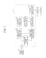
- FIG. 7 is a system configuration diagram illustrating a deceleration information notification device according to a fourth embodiment.
- the control unit 13 includes a deceleration degree calculating unit 33, a sound volume adjustment map storage unit 28, a sound volume adjustment member calculating unit 22, a frequency characteristic storage unit 23, an output frequency calculating unit 24, an output signal determining unit 25, and an output signal voltage conversion unit 26.
- the deceleration degree calculating unit 33 corresponds to a "deceleration degree detecting unit”.
- the control unit 13 performs a deceleration situation notification control process and notify a deceleration situation to a driver by causing the driver to hear a sound of which the sound volume varies depending on the deceleration situation (such as a driver's intention of deceleration or a vehicle deceleration state) in real time. That is, a degree of deceleration G is calculated on the basis of a variation (for example, a derivative value) of a vehicle speed per unit time, and the map shown in FIG. 8 is referred to, and a sound volume is adjusted by using a sound volume adjustment coefficient kg determined depending on the degree of deceleration G.
- a degree of deceleration G is calculated on the basis of a variation (for example, a derivative value) of a vehicle speed per unit time, and the map shown in FIG. 8 is referred to, and a sound volume is adjusted by using a sound volume adjustment coefficient kg determined depending on the degree of deceleration G.
- FIG. 8 is a diagram illustrating a map which is used to calculate the sound volume adjustment coefficient kg.
- the characteristic line has an inverted S shape. That is, the increasing rate of the sound volume adjustment coefficient kt with respect to the degree of deceleration G is set to be small in a region in which the degree of deceleration G is small and a region in which the degree of deceleration G is large and to be large in an intermediate region therebetween.
- the deceleration degree calculating unit 33 corresponds to the "deceleration degree detecting unit".
- the degree of deceleration G of the vehicle is calculated on the basis of a signal from the vehicle speed sensor 16, but the degree of deceleration G of vehicle may be directly detected with an acceleration sensor. According to this configuration, the process by the deceleration degree calculating unit 33 can be omitted.
- the sound volume of a deceleration sound is adjusted depending on only the degree of deceleration G, but the sound volume of a deceleration sound may be adjusted depending on the engine torque Te and the degree of deceleration G, as shown in FIG. 9 .
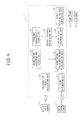
- FIG. 9 is a system configuration diagram illustrating a deceleration information notification device according to application example 2.
- the sound volume adjustment coefficient kt is calculated depending on the engine torque Te
- the sound volume adjustment coefficient kg is calculated depending on the degree of deceleration G
- the final output signal may be generated using the sum or product of the sound volume adjustment coefficients kt and kg.
- the weights of the sound volume adjustment coefficients kt and kg may be equal to each other (1:1 relationship) or different weights may be given thereto.
- a degree of notification of a deceleration situation is adjusted depending on a regeneration amount of a regeneration brake in a hybrid vehicle (HEV) or an electric vehicle (EV).
- HEV hybrid vehicle
- EV electric vehicle
- FIG. 10 is a system configuration diagram illustrating a deceleration information notification device according to a fifth embodiment.
- the deceleration information notification device includes a regeneration amount detecting unit 17, a control unit 13 constituted, for example, of a microcomputer, an amplifier 14, and a speaker 15.
- the control unit 13 corresponds to the "deceleration information setting unit” and the speaker 15 corresponds to the "notification unit”.
- the regeneration amount detecting unit 17 detects, for example, a target degree of deceleration or a regenerative torque instruction value in the regeneration brake, as the regeneration amount B.
- the regeneration amount detecting unit 17 corresponds to a "regeneration amount detecting unit”.
- the control unit 13 includes a sound volume adjustment map storage unit 28, a sound volume adjustment member calculating unit 22, a frequency characteristic storage unit 23, an output frequency calculating unit 24, an output signal determining unit 25, and an output signal voltage conversion unit 26.
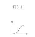
- the control unit 13 performs a deceleration situation notification control process and notifies a deceleration situation to a driver by causing the driver to hear a sound of which the sound volume varies depending on the deceleration situation (such as a driver's intention of deceleration or a vehicle deceleration state) in real time. That is, the map shown in FIG. 11 is referred to, and the sound volume is adjusted using the sound volume adjustment coefficient kb determined depending on the regeneration amount B.
- FIG. 11 is a diagram illustrating a map which is used to calculate the sound volume adjustment coefficient kb.
- the characteristic line has an inverted S shape. That is, the increasing rate of the sound volume adjustment coefficient kb with respect to the regeneration amount B is set to be small in a region in which the regeneration amount B is small and a region in which the regeneration amount B is large and to be large in an intermediate region therebetween.
- At least one of a driver's intention of deceleration and a vehicle deceleration state is notified as the deceleration situation to a driver by the use of a sound volume.
- the sound volume adjustment coefficient kb is calculated depending on the regeneration amount B and the sound volume is adjusted depending on the sound volume adjustment coefficient kb.
- the regeneration amount B correlated with the degree of deceleration of the vehicle is detected and the degree of notification of the deceleration situation is adjusted depending on the regeneration amount B, it is possible to more accurately notify the deceleration situation such as a driver's intention of deceleration or a vehicle deceleration state.
- the regeneration amount B of a regeneration braking system since the regeneration amount B of a regeneration braking system is used, it is possible to notify the deceleration information to a driver without newly adding a sensor detecting an engine torque, a vehicle speed, a degree of deceleration, or the like.
- the regeneration amount detecting unit 17 corresponds to the "regeneration amount detecting unit”.
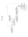
- the sound volume of a deceleration sound is adjusted depending on only the regeneration amount B, but the sound volume of a deceleration sound may be adjusted depending on the engine torque Te and the regeneration amount B, as shown in FIG. 12 .
- FIG. 12 is a system configuration diagram illustrating a deceleration information notification device according to application example 1.
- the sound volume adjustment coefficient kt is calculated depending on the engine torque Te
- the sound volume adjustment coefficient kb is calculated depending on the regeneration amount B
- the final output signal may be generated using the sum or product of the sound volume adjustment coefficients kt and kb.
- the weights of the sound volume adjustment coefficients kt and kb may be equal to each other (1: 1 relationship) or different weights may be given thereto.
- a deceleration state is notified to a driver through the use of a lamp.
- FIG. 13 is a system configuration diagram illustrating a deceleration information "notification device according to a sixth embodiment.
- the deceleration information notification device includes an engine torque sensor 11, a control unit 13 constituted, for example, of a microcomputer, a signal receiving unit 41, a voltage generating unit 42, and a lamp 43.
- the engine torque sensor 11 corresponds to the "drive torque detecting unit”
- the control unit 13 corresponds to the "deceleration information setting unit”
- the lamp 43 corresponds to the "notification unit”.
- the lamp 43 is disposed at a position which can be viewed by a driver.
- the control unit 13 includes a sound volume adjustment map storage unit 28, a threshold value storage unit 31, a threshold value comparing unit 32, and a lamp turn-on signal generating unit 34.
- the control unit 13 performs a deceleration situation notification control process and notifies a deceleration situation to a driver by turning on the lamp 43 depending on the deceleration situation (such as a driver's intention of deceleration or a vehicle deceleration state). That is, when the engine torque Te is larger than the threshold value th, the lamp 43 is turned on.
- the deceleration situation can be notified to a driver by turning on the lamp 43, i.e., by a display. Therefore, even in a traveling scene in which a sound cannot be heard well due to an influence of an external environment or an influence from a road surface, a driver can visually recognize the deceleration situation.
- the lamp 43 corresponds to the "notification unit".
- a deceleration state is notified to a driver through the use of a vibration generator.
- FIG. 14 is a system configuration diagram illustrating a deceleration information notification device according to a seventh embodiment.
- the deceleration information notification device includes an engine torque sensor 11, a control unit 13 constituted, for example, of a microcomputer, a signal receiving unit 51, a vibration generator 52, and a lamp 53.
- the engine torque sensor 11 corresponds to the "drive torque detecting unit”
- the control unit 13 corresponds to the "deceleration information setting unit”
- the vibration generator 52 and the lamp 53 correspond to the "notification unit”.
- the vibration generator 52 is disposed in a steering wheel.
- the lamp 53 is disposed at a position which can be viewed by a driver.
- the control unit 13 includes a sound volume adjustment map storage unit 28, a threshold value storage unit 31, a threshold value comparing unit 32, and a vibration signal generating unit 35.
- the control unit 13 performs a deceleration situation notification control process and notifies a deceleration situation to a driver by causing the vibration generator 52 to vibrate and turning on the lamp 53 depending on the deceleration situation (such as a driver's intention of deceleration or a vehicle deceleration state). That is, when the engine torque Te is larger than the threshold value th, the vibration generator 52 is caused to vibrate and the lamp 53 is turned on.
- the deceleration situation can be notified to a driver by causing the vibration generator 52 to vibrate and turning on the lamp 53. Therefore, even in a traveling scene in which a sound cannot be heard well due to an influence of an external environment or an influence from a road surface, a driver can tactually and visually recognize the deceleration situation.
- the vibration generator 52 and the lamp 53 correspond to the "notification unit".
Landscapes
- Engineering & Computer Science (AREA)
- Automation & Control Theory (AREA)
- Mechanical Engineering (AREA)
- Human Computer Interaction (AREA)
- Transportation (AREA)
- Physics & Mathematics (AREA)
- General Physics & Mathematics (AREA)
- Circuit For Audible Band Transducer (AREA)
- Control Of Vehicle Engines Or Engines For Specific Uses (AREA)
- Hybrid Electric Vehicles (AREA)
- Control Of Transmission Device (AREA)
- Fittings On The Vehicle Exterior For Carrying Loads, And Devices For Holding Or Mounting Articles (AREA)
Abstract
Description
- The present invention relates to a deceleration information notification device and a deceleration information notification method.
- In the related art described in Patent Document 1, a sound pressure of a sound effect is adjusted depending on the rotational frequency of an engine, and the output of the sound effect is stopped when a variation per unit time of the rotational frequency is greater than a predetermined value.
- Patent Document 1: Japanese Patent No.
4173891 - As described in the related art, when the output of a sound effect is stopped on the basis of the variation of the rotational frequency per unit time, it is difficult to accurately notify a deceleration situation such as a driver' s intention of deceleration or a vehicle deceleration state to a driver.
- An object of the present invention is to more accurately notify a deceleration situation such as a driver's intention of deceleration or a vehicle deceleration state to a driver.
- According to an aspect of the present invention, there is provided a vehicle deceleration degree control device which detects a drive torque of a rotational drive source, sets deceleration information indicating at least one of a driver's intention of deceleration and a vehicle deceleration state depending on the drive torque when the drive torque has a negative value, and notifies the set deceleration information to a driver.
- According to the vehicle deceleration degree control device of the aspect of the present invention, since the degree of notification of the deceleration situation is adjusted depending on the drive torque having a negative value, it is possible to more accurately notify the deceleration situation such as a driver's intention of deceleration or a vehicle deceleration state.
-
-
FIG. 1 is a system configuration diagram illustrating a deceleration information notification device. -
FIG. 2 is a flowchart illustrating a deceleration situation notification control process. -
FIG. 3 is a system configuration diagram illustrating a deceleration information notification device according to a second embodiment. -
FIG. 4 is a diagram illustrating a map which is used to calculate a sound volume adjustment coefficient kt. -
FIG. 5 is a system configuration diagram illustrating a deceleration information notification device according to a third embodiment. -
FIG. 6 is a flowchart illustrating a deceleration situation notification control process according to the third embodiment. -
FIG. 7 is a system configuration diagram illustrating a deceleration information notification device according to a fourth embodiment. -
FIG. 8 is a diagram illustrating a map which is used to calculate a sound volume adjustment coefficient kg. -
FIG. 9 is a system configuration diagram illustrating a deceleration information notification device according to application example 2 of the fourth embodiment. -
FIG. 10 is a system configuration diagram illustrating a deceleration information notification device according to a fifth embodiment. -
FIG. 11 is a diagram illustrating a map which is used to calculate a sound volume adjustment coefficient kb. -
FIG. 12 is a system configuration diagram illustrating a deceleration information notification device according to application example 1 of the fifth embodiment. -
FIG. 13 is a system configuration diagram illustrating a deceleration information notification device according to a sixth embodiment. -
FIG. 14 is a system configuration diagram illustrating a deceleration information notification device according to a seventh embodiment. - Hereinafter, embodiments of the present invention will be described with reference to the accompanying drawings.
-
FIG. 1 is a system configuration diagram illustrating a deceleration information notification device. - In this embodiment, the deceleration information notification device includes an
engine torque sensor 11 detecting an engine torque Te, acontrol unit 13 constituted, for example, of a microcomputer, anamplifier 14, and aspeaker 15. Theengine torque sensor 11 corresponds to a "drive torque detecting unit", thecontrol unit 13 corresponds to a "deceleration information setting unit", and thespeaker 15 corresponds to a "notification unit". - Instead of using the
engine torque sensor 11, the engine torque Te may be acquired through CAN communications or the engine torque Te may be calculated on the basis of an engine speed, a transmission gear ratio, a vehicle speed, and the like. - While the case where the rotational drive source is an engine is described, in the case where a hybrid electric vehicle (HEV) travels with a motor or when an electric vehicle (EV) travels, a motor torque is detected as the drive torque of the rotational drive source.
- The
control unit 13 includes a sound volume adjustment linearexpression storage unit 21, a sound volume adjustmentmember calculating unit 22, a frequencycharacteristic storage unit 23, an outputfrequency calculating unit 24, an outputsignal determining unit 25, an output signalvoltage conversion unit 26, and asign determining unit 27. - The
control unit 13 performs a deceleration situation notification control process and notifies a deceleration situation to a driver by causing the driver to hear a sound of which the sound volume varies depending on the deceleration situation (such as a driver's intention of deceleration or a vehicle deceleration state) in real time. The sound volume is adjusted by acquiring a signal indicating the engine torque Te, and by using a sound volume adjustment coefficient kt when the engine torque has a negative value, the sound value adjustment coefficient kt being determined depending on the engine torque Te. - The deceleration situation notification control process which is performed every predetermined time (for example, 10 msec) by the
control unit 13 will be described below. -
FIG. 2 is a flowchart illustrating the deceleration situation notification control process. - First, in step S11, the engine torque Te is read.
- Subsequently, in step S12 corresponding to a process by the
sign determining unit 27, it is determined whether the engine torque Te has a negative value. When the determination result is "Te≥0", it is determined that deceleration information indicating the intention of deceleration or the deceleration state is not necessary and the process returns to a predetermined main program. On the other hand, when the determination result is "Te<0", the process progresses to step S13 to notify deceleration information to a driver. - Subsequently, in step S13 corresponding to a process by the sound volume adjustment
member calculating unit 22, the sound volume adjustment coefficient kt depending on the engine torque Te is calculated using a sound volume adjustment linear expression stored in the sound volume adjustment linearexpression storage unit 21. The sound volume adjustment linear expression is set so that as the larger the absolute value of the engine torque Te is (the larger in the negative direction), the larger the sound volume adjustment coefficient kt is. - Subsequently, in step S14 corresponding to a process by the output
frequency calculating unit 24, a tone (deceleration sound) depending on an order component of the engine torque is set from sound source data. - The sound source data is a wav file, a midi file or the like stored in advance in the frequency
characteristic storage unit 23 of thecontrol unit 13. The sound source data can be changed through an external terminal such as a USB, or can be selected from preset files and can be rewritten. - Subsequently, in step S15 corresponding to a process by the output
signal determining unit 25, an output signal is generated depending on the sound volume adjustment coefficient kt and the tone depending on the order component of the engine torque. - Subsequently, in step S16 corresponding to a process by the output signal
voltage conversion unit 26, the voltage of the output signal is converted, the output signal is output to theamplifier 14, and the deceleration sound is output through thespeaker 15. - At least one of a driver's intention of deceleration and a vehicle deceleration state is notified as a deceleration situation to a driver by the use of a sound volume.
- Specifically, when the engine torque Te has a negative value ("YES" in step S12), the sound volume adjustment coefficient kt is calculated depending on the engine torque Te (step S13) and a deceleration sound with the sound volume adjusted depending on the sound volume adjustment coefficient kt is output (steps S14 to S16).
- In this way, since the degree of notification of the deceleration situation is adjusted depending on the engine torque Te having a negative value, it is possible to more accurately notify the deceleration situation such as a driver's intention of deceleration or a vehicle deceleration state.
- That is, at the time of deceleration by an engine brake, the engine torque Te has a negative value, and the larger the absolute value thereof is, the larger the degree of deceleration by the engine brake is. Therefore, information on the engine torque Te is acquired in real time and the sound volume of the deceleration sound increases as the absolute value of the engine torque Te increases, when the engine torque Te has a negative value. In this way, by controlling the sound volume depending on the engine torque Te correlated with the degree of deceleration by the engine brake, it is possible to more appropriately control the sound volume with regard to the vehicle deceleration.
- In this configuration, the
engine torque sensor 11 corresponds to the "drive torque detecting unit", thecontrol unit 13 corresponds to the "deceleration information setting unit", and thespeaker 15 corresponds to the "notification unit". -
- (1) According to the deceleration information notification device, when the engine torque Te has a negative value, the sound volume of the deceleration sound is adjusted depending on the engine torque Te and the deceleration sound is transmitted to a driver.
In this way, since the degree of notification of the deceleration situation is adjusted depending on the engine torque Te having a negative value, it is possible to more accurately notify the deceleration situation such as a driver's intention of deceleration or a vehicle deceleration state. - (2) According to the deceleration information notification device, deceleration information is notified to a driver by outputting a deceleration sound through the
speaker 15.
Accordingly, it is possible to easily notify the deceleration information to the driver. - (3) According to the deceleration information notification method, when the engine torque Te has a negative value, the sound volume of the deceleration sound is adjusted depending on the engine torque Te and the deceleration sound is transmitted to a driver.
- In this way, since the degree of notification of the deceleration situation is adjusted depending on the engine torque Te having a negative value, it is possible to more accurately notify the deceleration situation such as a driver's intention of deceleration or a vehicle deceleration state.
- In this embodiment, a map instead of the sound volume adjustment linear expression is referred to at the time of calculating a sound volume adjustment coefficient kt.
-
FIG. 3 is a system configuration diagram illustrating a deceleration information notification device according to a second embodiment. - The
control unit 13 includes a sound volume adjustmentmap storage unit 28, a sound volume adjustmentmember calculating unit 22, a frequencycharacteristic storage unit 23, an outputfrequency calculating unit 24, an outputsignal determining unit 25, an output signalvoltage conversion unit 26, and asign determining unit 27. -
FIG. 4 is a diagram illustrating a map which is used to calculate the sound volume adjustment coefficient kt. - In this map, the larger the engine torque Te is in the negative direction, the larger the sound volume adjustment coefficient kt is. The characteristic line has an inverted S shape. That is, the increasing rate of the sound volume adjustment coefficient kt with respect to the engine torque Te is set to be small in a region in which the absolute value of the engine torque Te is small and a region in which the absolute value of the engine torque Te is large and to be large in an intermediate region therebetween.
- When the engine torque Te has a negative value ("YES" in step S12), the sound volume adjustment coefficient kt is calculated depending on the engine torque Te with reference to the map shown in
FIG. 4 (step S13) and the sound volume is adjusted depending on the sound volume adjustment coefficient kt. - In this way, since the degree of notification of the deceleration situation is adjusted depending on the engine torque Te having a negative value, it is possible to more accurately notify the deceleration situation such as a driver's intention of deceleration or a vehicle deceleration state.
- By using the map for controlling, it is possible to control the sound volume having a degree of freedom. That is, the sound volume can be adjusted depending on a background noise or an engine or transmission state of a vehicle and thus the degree of freedom increases. By setting the characteristic line to an inverted S shape, it is possible to effectively transmit the deceleration sound to the driver when the degree of deceleration gradually increases, i.e., when it is necessary to learn that the vehicle is decelerated since a speed decreasing rate increases.
-
- (1) According to the deceleration information notification device, the map which defines the sound volume adjustment coefficient kt depending on the engine torque Te is referred to.
- In this way, by using the map for controlling, it is possible to easily control the sound volume with a degree of freedom.
- In this embodiment, when the absolute value of the engine torque Te is larger than a threshold value th, the sound volume of a deceleration sound is adjusted.
-
FIG. 5 is a system configuration diagram illustrating a deceleration information notification device according to a third embodiment. - The
control unit 13 includes a thresholdvalue storage unit 31, a thresholdvalue comparing unit 32, a frequencycharacteristic storage unit 23, an outputfrequency calculating unit 24, an outputsignal determining unit 25, an output signalvoltage conversion unit 26, and asign determining unit 27. -
FIG. 6 is a flowchart illustrating a deceleration situation notification control process according to the third embodiment. - First, in step S31, the engine torque Te is read.
- Subsequently, in step S32 corresponding to a process by the
sign determining unit 27, it is determined whether the engine torque Te has a negative value. When the determination result is "Te≥0", it is determined that deceleration information indicating the intention of deceleration or the deceleration state is not necessary and the process returns to a predetermined main program. On the other hand, when the determination result is "Te<0", the process progresses to step S33. - Subsequently, in step S33 corresponding to a process by the threshold
value comparing unit 32, the threshold value th stored in advance in the thresholdvalue storage unit 31 is referred to, and it is determined whether the absolute value of the engine torque Te is larger than the threshold value. When the determination result is "|Te|≤th", it is determined that the deceleration information indicating the intention of deceleration or the deceleration state is not necessary and the process returns to a predetermined main program. On the other hand, when the determination result is "|Te|>th", the process progresses to step S34 to notify the deceleration information indicating an intention of deceleration or a deceleration state to a driver. - Subsequently, in step S34 corresponding to a process by the output
frequency calculating unit 24, a tone (deceleration sound) depending on an order component of the engine torque is set from sound source data. - The sound source data is a wav file, a midi file or the like stored in advance in the frequency
characteristic storage unit 23 of thecontrol unit 13. The sound source data can be changed through an external terminal such as a USB, or can be selected from preset files and can be rewritten. - Subsequently, in step S35 corresponding to a process by the output
signal determining unit 25, an output signal is generated depending on the tone depending on the order component of the engine torque. - Subsequently, in step S36 corresponding to a process by the output signal
voltage conversion unit 26, the voltage of the output signal is converted, the output signal is output to theamplifier 14, and the deceleration sound is output through thespeaker 15. - When the engine torque Te has a negative value ("YES" in step S32) and the absolute value of the engine torque Te is larger than the threshold value th ("YES" in step S33), a deceleration sound is output (steps S34 to S36).
- In this way, since the degree of notification of the deceleration situation is adjusted depending on the engine torque Te having a negative value, it is possible to more accurately notify the deceleration situation such as a driver' s intention of deceleration or a vehicle deceleration state.
- The threshold value th for the engine torque Te having a negative value is set and the deceleration sound is output when the absolute value |Te| of the engine torque is larger than the threshold value th. This process is performed in real time. Accordingly, since the deceleration sound can be switched on and off while maintaining a function of notifying deceleration information with a sound, it is possible to simplify control logics.
-
- (1) When the engine torque Te has a negative value ("YES" in step S32) and the absolute value of the engine torque Te is larger than the threshold value th ("YES" in step S33), deceleration information is notified to a driver.
- In this way, by outputting the deceleration sound when the absolute value |Te| of the engine torque is larger than the threshold value th, it is possible to simplify control logics while maintaining the function of notifying the deceleration information with a sound.
- In this embodiment, a degree of notification of a deceleration situation is adjusted depending on the degree of deceleration of a vehicle.
-
FIG. 7 is a system configuration diagram illustrating a deceleration information notification device according to a fourth embodiment. - In this embodiment, the deceleration information notification device includes a
vehicle speed sensor 16, acontrol unit 13 constituted, for example, of a microcomputer, anamplifier 14, and aspeaker 15. Here, thecontrol unit 13 corresponds to the "deceleration information setting unit" and thespeaker 15 corresponds to the "notification unit". - The
control unit 13 includes a decelerationdegree calculating unit 33, a sound volume adjustmentmap storage unit 28, a sound volume adjustmentmember calculating unit 22, a frequencycharacteristic storage unit 23, an outputfrequency calculating unit 24, an outputsignal determining unit 25, and an output signalvoltage conversion unit 26. Here, the decelerationdegree calculating unit 33 corresponds to a "deceleration degree detecting unit". - The
control unit 13 performs a deceleration situation notification control process and notify a deceleration situation to a driver by causing the driver to hear a sound of which the sound volume varies depending on the deceleration situation (such as a driver's intention of deceleration or a vehicle deceleration state) in real time. That is, a degree of deceleration G is calculated on the basis of a variation (for example, a derivative value) of a vehicle speed per unit time, and the map shown inFIG. 8 is referred to, and a sound volume is adjusted by using a sound volume adjustment coefficient kg determined depending on the degree of deceleration G. -
FIG. 8 is a diagram illustrating a map which is used to calculate the sound volume adjustment coefficient kg. - In this map, the larger the degree of deceleration G is, the larger the sound volume adjustment coefficient kt is. The characteristic line has an inverted S shape. That is, the increasing rate of the sound volume adjustment coefficient kt with respect to the degree of deceleration G is set to be small in a region in which the degree of deceleration G is small and a region in which the degree of deceleration G is large and to be large in an intermediate region therebetween.
- At least one of a drivrer's intention of deceleration and a vehicle deceleration state is notified as the deceleration situation to a driver by the use of a sound volume. Specifically, the sound volume adjustment coefficient kg is calculated depending on the degree of deceleration G and the sound volume is adjusted depending on the sound volume adjustment coefficient kt.
- In this way, since the degree of notification of the deceleration situation is adjusted depending on the degree of deceleration G, it is possible to more accurately notify the deceleration situation such as a driver's intention of deceleration or a vehicle deceleration state.
- That is, information on the degree of deceleration G is acquired in real time and the sound volume of the deceleration sound increases as the degree of deceleration G increases. In this way, by controlling the sound volume depending on the degree of deceleration G by the engine brake, it is possible to more appropriately control the sound volume with regard to the degree of deceleration of the vehicle.
- In this configuration, the deceleration
degree calculating unit 33 corresponds to the "deceleration degree detecting unit". -
- (1) The degree of deceleration G is calculated on the basis of the vehicle speed and the sound volume of a deceleration sound is adjusted depending on the degree of deceleration G and the deceleration sound is transmitted to a driver.
- In this way, since the degree of notification of the deceleration situation is adjusted depending on the degree of deceleration G, it is possible to more accurately notify the deceleration situation such as a driver's intention of deceleration or a vehicle deceleration state.
- In this embodiment, the degree of deceleration G of the vehicle is calculated on the basis of a signal from the
vehicle speed sensor 16, but the degree of deceleration G of vehicle may be directly detected with an acceleration sensor. According to this configuration, the process by the decelerationdegree calculating unit 33 can be omitted. - In this embodiment, the sound volume of a deceleration sound is adjusted depending on only the degree of deceleration G, but the sound volume of a deceleration sound may be adjusted depending on the engine torque Te and the degree of deceleration G, as shown in
FIG. 9 . -
FIG. 9 is a system configuration diagram illustrating a deceleration information notification device according to application example 2. - Here, the
engine torque sensor 11 and thesign determining unit 27 are added. The sound volume adjustment coefficient kt is calculated depending on the engine torque Te, the sound volume adjustment coefficient kg is calculated depending on the degree of deceleration G, and the final output signal may be generated using the sum or product of the sound volume adjustment coefficients kt and kg. In this case, the weights of the sound volume adjustment coefficients kt and kg may be equal to each other (1:1 relationship) or different weights may be given thereto. - In this embodiment, a degree of notification of a deceleration situation is adjusted depending on a regeneration amount of a regeneration brake in a hybrid vehicle (HEV) or an electric vehicle (EV).
-
FIG. 10 is a system configuration diagram illustrating a deceleration information notification device according to a fifth embodiment. - In this embodiment, the deceleration information notification device includes a regeneration
amount detecting unit 17, acontrol unit 13 constituted, for example, of a microcomputer, anamplifier 14, and aspeaker 15. Here, thecontrol unit 13 corresponds to the "deceleration information setting unit" and thespeaker 15 corresponds to the "notification unit". - The regeneration
amount detecting unit 17 detects, for example, a target degree of deceleration or a regenerative torque instruction value in the regeneration brake, as the regeneration amount B. Here, the regenerationamount detecting unit 17 corresponds to a "regeneration amount detecting unit". - The
control unit 13 includes a sound volume adjustmentmap storage unit 28, a sound volume adjustmentmember calculating unit 22, a frequencycharacteristic storage unit 23, an outputfrequency calculating unit 24, an outputsignal determining unit 25, and an output signalvoltage conversion unit 26. - The
control unit 13 performs a deceleration situation notification control process and notifies a deceleration situation to a driver by causing the driver to hear a sound of which the sound volume varies depending on the deceleration situation (such as a driver's intention of deceleration or a vehicle deceleration state) in real time. That is, the map shown inFIG. 11 is referred to, and the sound volume is adjusted using the sound volume adjustment coefficient kb determined depending on the regeneration amount B. -
FIG. 11 is a diagram illustrating a map which is used to calculate the sound volume adjustment coefficient kb. - In this map, the larger the regeneration amount B is, the larger the sound volume adjustment coefficient kb is. The characteristic line has an inverted S shape. That is, the increasing rate of the sound volume adjustment coefficient kb with respect to the regeneration amount B is set to be small in a region in which the regeneration amount B is small and a region in which the regeneration amount B is large and to be large in an intermediate region therebetween.
- At least one of a driver's intention of deceleration and a vehicle deceleration state is notified as the deceleration situation to a driver by the use of a sound volume. Specifically, the sound volume adjustment coefficient kb is calculated depending on the regeneration amount B and the sound volume is adjusted depending on the sound volume adjustment coefficient kb.
- In this way, since the regeneration amount B correlated with the degree of deceleration of the vehicle is detected and the degree of notification of the deceleration situation is adjusted depending on the regeneration amount B, it is possible to more accurately notify the deceleration situation such as a driver's intention of deceleration or a vehicle deceleration state.
- That is, information on the regeneration amount B is acquired in real time and the sound volume of the deceleration sound increases as the regeneration amount B increases. In this way, by controlling the sound volume depending on the regeneration amount of the regeneration brake, it is possible to more appropriately control the sound volume with regard to the vehicle deceleration situation.
- Since the regeneration amount B of a regeneration braking system is used, it is possible to notify the deceleration information to a driver without newly adding a sensor detecting an engine torque, a vehicle speed, a degree of deceleration, or the like.
- In this configuration, the regeneration
amount detecting unit 17 corresponds to the "regeneration amount detecting unit". -
- (1) The regeneration amount B of the regeneration brake is calculated and the sound volume of a deceleration sound is adjusted depending on the regeneration amount B and the deceleration sound is transmitted to a driver.
- In this way, since the degree of "notification of the deceleration situation is adjusted depending on the regeneration amount B, it is possible to more accurately notify the deceleration situation such as a driver's intention of deceleration or a vehicle deceleration state.
- In this embodiment, the sound volume of a deceleration sound is adjusted depending on only the regeneration amount B, but the sound volume of a deceleration sound may be adjusted depending on the engine torque Te and the regeneration amount B, as shown in
FIG. 12 . -
FIG. 12 is a system configuration diagram illustrating a deceleration information notification device according to application example 1. - Here, the
engine torque sensor 11 and thesign determining unit 27 are added. The sound volume adjustment coefficient kt is calculated depending on the engine torque Te, the sound volume adjustment coefficient kb is calculated depending on the regeneration amount B, and the final output signal may be generated using the sum or product of the sound volume adjustment coefficients kt and kb. In this case, the weights of the sound volume adjustment coefficients kt and kb may be equal to each other (1: 1 relationship) or different weights may be given thereto. - In this embodiment, a deceleration state is notified to a driver through the use of a lamp.
-
FIG. 13 is a system configuration diagram illustrating a deceleration information "notification device according to a sixth embodiment. - In this embodiment, the deceleration information notification device includes an
engine torque sensor 11, acontrol unit 13 constituted, for example, of a microcomputer, asignal receiving unit 41, avoltage generating unit 42, and alamp 43. Here, theengine torque sensor 11 corresponds to the "drive torque detecting unit", thecontrol unit 13 corresponds to the "deceleration information setting unit", and thelamp 43 corresponds to the "notification unit". - The
lamp 43 is disposed at a position which can be viewed by a driver. - The
control unit 13 includes a sound volume adjustmentmap storage unit 28, a thresholdvalue storage unit 31, a thresholdvalue comparing unit 32, and a lamp turn-onsignal generating unit 34. - The
control unit 13 performs a deceleration situation notification control process and notifies a deceleration situation to a driver by turning on thelamp 43 depending on the deceleration situation (such as a driver's intention of deceleration or a vehicle deceleration state). That is, when the engine torque Te is larger than the threshold value th, thelamp 43 is turned on. - In this embodiment, the deceleration situation can be notified to a driver by turning on the
lamp 43, i.e., by a display. Therefore, even in a traveling scene in which a sound cannot be heard well due to an influence of an external environment or an influence from a road surface, a driver can visually recognize the deceleration situation. - In this configuration, the
lamp 43 corresponds to the "notification unit". -
- (1) According to the deceleration information notification device, it is possible to notify deceleration information to a driver by turning on the
lamp 43. - Accordingly, it is possible to easily notify deceleration information to a driver. In addition, even in a traveling scene in which a sound cannot be heard well due to an influence of an external environment or an influence from a road surface, a driver can visually recognize the deceleration situation.
- In this embodiment, a deceleration state is notified to a driver through the use of a vibration generator.
-
FIG. 14 is a system configuration diagram illustrating a deceleration information notification device according to a seventh embodiment. - In this embodiment, the deceleration information notification device includes an
engine torque sensor 11, acontrol unit 13 constituted, for example, of a microcomputer, asignal receiving unit 51, avibration generator 52, and alamp 53. Here, theengine torque sensor 11 corresponds to the "drive torque detecting unit", thecontrol unit 13 corresponds to the "deceleration information setting unit", and thevibration generator 52 and thelamp 53 correspond to the "notification unit". - The
vibration generator 52 is disposed in a steering wheel. - The
lamp 53 is disposed at a position which can be viewed by a driver. - The
control unit 13 includes a sound volume adjustmentmap storage unit 28, a thresholdvalue storage unit 31, a thresholdvalue comparing unit 32, and a vibrationsignal generating unit 35. - The
control unit 13 performs a deceleration situation notification control process and notifies a deceleration situation to a driver by causing thevibration generator 52 to vibrate and turning on thelamp 53 depending on the deceleration situation (such as a driver's intention of deceleration or a vehicle deceleration state). That is, when the engine torque Te is larger than the threshold value th, thevibration generator 52 is caused to vibrate and thelamp 53 is turned on. - In this embodiment, the deceleration situation can be notified to a driver by causing the
vibration generator 52 to vibrate and turning on thelamp 53. Therefore, even in a traveling scene in which a sound cannot be heard well due to an influence of an external environment or an influence from a road surface, a driver can tactually and visually recognize the deceleration situation. - In this configuration, the
vibration generator 52 and thelamp 53 correspond to the "notification unit". -
- (1) According to the deceleration information notification device, it is possible to notify deceleration information to a driver by causing the
vibration generator 52 to vibrate. - Accordingly, it is possible to easily notify deceleration information to a driver. In addition, even in a traveling scene in which a sound cannot be heard well due to an influence of an external environment or an influence from a road surface, a driver can visually recognize the deceleration situation.
- Priority is claimed on Japanese Patent Application No.
2011-119614 (filed on May 27, 2011 - While the present invention is described with reference to a definite number of embodiments, the scope of the present invention is not limited to the embodiments but modifications of the embodiments based on the above disclosure are obvious to those skilled in the art.
-
- 11:
- engine torque sensor
- 13:
- control unit
- 14:
- amplifier
- 15:
- speaker
- 16:
- vehicle speed sensor
- 17:
- regeneration amount detecting unit
- 21:
- sound volume adjustment linear expression storage unit
- 22:
- sound volume adjustment member calculating unit
- 23:
- frequency characteristic storage unit
- 24:
- output frequency calculating unit
- 25:
- output signal determining unit
- 26:
- output signal voltage conversion unit
- 27:
- sign determining unit
- 28:
- sound volume adjustment map storage unit
- 31:
- threshold value storage unit
- 32:
- threshold value comparing unit
- 33:
- deceleration degree calculating unit
- 34:
- lamp turn-on signal generating unit
- 35:
- vibration signal generating unit
- 41:
- signal receiving unit
- 42:
- voltage generating unit
- 43:
- lamp
- 51:
- signal receiving unit
- 52:
- vibration generator
- 53:
- lamp
Claims (11)
- A deceleration information notification device comprising:a drive torque detecting unit for detecting a drive torque of a rotational drive source;a deceleration information setting unit for setting deceleration information indicating at least one of a driver' s intention of deceleration and a vehicle deceleration state depending on the drive torque when the drive torque detected by the drive torque detecting unit has a negative value; anda notification unit for notifying the deceleration information set by the deceleration information setting unit to a driver.
- The deceleration information notification device according to claim 1, wherein the deceleration information setting unit sets the deceleration information when the drive torque detected by the drive torque detecting unit has a negative value and when the absolute value of the drive torque is larger than a predetermined threshold value.
- The deceleration information notification device according to claim 1, further comprising a regeneration amount detecting unit for detecting a regeneration amount of a regeneration brake,
wherein the deceleration information setting unit sets the deceleration information depending on the drive torque detected by the drive torque detecting unit and the regeneration amount detected by the regeneration amount detecting unit. - The deceleration information notification device according to claim 1, further comprising a deceleration degree detecting unit for detecting a degree of deceleration of a vehicle,
wherein the deceleration information setting unit sets the deceleration information depending on the drive torque detected by the drive torque detecting unit and the degree of deceleration detected by the deceleration degree detecting unit. - The deceleration information notification device according to claim 1, wherein the notification unit notifies the deceleration information to the driver by outputting a deceleration sound from a speaker.
- The deceleration information notification device according to claim 1, wherein the notification unit notifies the deceleration information to the driver by displaying the deceleration state on a display device.
- The deceleration information notification device according to claim 1, wherein the notification unit notifies the deceleration information to the driver by causing a vibration generator to vibrate a steering wheel.
- The deceleration information notification device according to claim 1, wherein the deceleration information setting unit refers to a map which defines the deceleration information depending on the drive torque detected by the drive torque detecting unit.
- A deceleration information notification device comprising:a regeneration amount detecting unit for detecting a regeneration amount of a regeneration brake;a deceleration information setting unit for setting deceleration information indicating at least one of a driver' s intention of deceleration and a vehicle deceleration state depending on the regeneration amount detected by the regeneration amount detecting unit; anda notification unit for notifying the deceleration information set by the deceleration information setting unit to a driver.
- A deceleration information notification device comprising:a deceleration degree detecting unit for detecting a degree of deceleration of a vehicle;a deceleration information setting unit for setting deceleration information indicating at least one of a driver' s intention of deceleration and a vehicle deceleration state depending on the degree of deceleration detected by the deceleration degree detecting unit; anda notification unit for notifying the deceleration information set by the deceleration information setting unit to a driver.
- A deceleration information notification method comprising:detecting a drive torque of a rotational drive source; andnotifying deceleration information indicating at least one of a driver's intention of deceleration and a vehicle deceleration state depending on the drive torque to a driver when the detected drive torque has a negative value.
Applications Claiming Priority (2)
| Application Number | Priority Date | Filing Date | Title |
|---|---|---|---|
| JP2011119614A JP5170286B2 (en) | 2011-05-27 | 2011-05-27 | Deceleration information transmission device and deceleration information transmission method |
| PCT/JP2012/001187 WO2012164784A1 (en) | 2011-05-27 | 2012-02-22 | Deceleration information transmission device and deceleration information transmission method |
Publications (3)
| Publication Number | Publication Date |
|---|---|
| EP2716501A1 true EP2716501A1 (en) | 2014-04-09 |
| EP2716501A4 EP2716501A4 (en) | 2016-01-20 |
| EP2716501B1 EP2716501B1 (en) | 2020-06-17 |
Family
ID=47258663
Family Applications (1)
| Application Number | Title | Priority Date | Filing Date |
|---|---|---|---|
| EP12793872.8A Active EP2716501B1 (en) | 2011-05-27 | 2012-02-22 | Deceleration information transmission device and deceleration information transmission method |
Country Status (5)
| Country | Link |
|---|---|
| US (1) | US9229022B2 (en) |
| EP (1) | EP2716501B1 (en) |
| JP (1) | JP5170286B2 (en) |
| CN (1) | CN103702869B (en) |
| WO (1) | WO2012164784A1 (en) |
Cited By (1)
| Publication number | Priority date | Publication date | Assignee | Title |
|---|---|---|---|---|
| WO2018041607A1 (en) * | 2016-09-01 | 2018-03-08 | Bayerische Motoren Werke Aktiengesellschaft | Method, apparatus and computer program for producing and transmitting a piece of driver information |
Families Citing this family (5)
| Publication number | Priority date | Publication date | Assignee | Title |
|---|---|---|---|---|
| JP6186619B2 (en) * | 2013-12-25 | 2017-08-30 | 三菱自動車工業株式会社 | Electric vehicle stop lamp lighting control device |
| JP6186618B2 (en) * | 2013-12-25 | 2017-08-30 | 三菱自動車工業株式会社 | Electric vehicle stop lamp lighting control device |
| JP6424614B2 (en) * | 2014-12-22 | 2018-11-21 | 三菱自動車工業株式会社 | Control device for stop lamp |
| KR102644371B1 (en) * | 2018-12-06 | 2024-03-07 | 현대자동차주식회사 | A driving sound control system and the method of it |
| JP2025113976A (en) * | 2024-01-23 | 2025-08-04 | 本田技研工業株式会社 | Active sound effect generating device and active sound effect generating method |
Family Cites Families (20)
| Publication number | Priority date | Publication date | Assignee | Title |
|---|---|---|---|---|
| JP3753511B2 (en) * | 1997-08-27 | 2006-03-08 | 本田技研工業株式会社 | Electric power steering device |
| JP3896240B2 (en) * | 2000-03-24 | 2007-03-22 | 住友電工ブレーキシステムズ株式会社 | Control method of regenerative cooperative brake system |
| US6559762B1 (en) * | 2002-01-02 | 2003-05-06 | Ford Global Technologies, Llc | Multi channel braking notification system |
| JP3747857B2 (en) * | 2002-01-31 | 2006-02-22 | トヨタ自動車株式会社 | Vehicle deceleration display control device |
| JP3949047B2 (en) * | 2002-11-05 | 2007-07-25 | ダイハツ工業株式会社 | Vehicle control device |
| JP3915699B2 (en) * | 2002-12-27 | 2007-05-16 | アイシン・エィ・ダブリュ株式会社 | Control device for hybrid vehicle |
| JP4173891B2 (en) | 2005-03-22 | 2008-10-29 | 本田技研工業株式会社 | Sound effect generator for moving objects |
| JP4715351B2 (en) * | 2005-07-19 | 2011-07-06 | 株式会社デンソー | Steering control system |
| DE102005044455A1 (en) * | 2005-09-17 | 2007-05-03 | Bayerische Motoren Werke Ag | A method of warning the driver of a motor vehicle equipped with a vehicle speed control system |
| JP4221418B2 (en) * | 2006-03-24 | 2009-02-12 | 本田技研工業株式会社 | Sound effect generator for vehicles |
| US8059829B2 (en) | 2006-03-24 | 2011-11-15 | Honda Motor Co., Ltd. | Sound effect producing apparatus for vehicle |
| JP4894546B2 (en) * | 2007-02-14 | 2012-03-14 | 株式会社デンソー | Control information storage device and program |
| JP2009177860A (en) * | 2008-01-21 | 2009-08-06 | Toyota Motor Corp | Vehicle control device and vehicle equipped with the same |
| JP4495234B2 (en) * | 2008-07-31 | 2010-06-30 | 富士通テン株式会社 | Fuel saving driving diagnosis device, fuel saving driving diagnosis system and fuel saving driving diagnosis method |
| US8055422B2 (en) * | 2008-08-08 | 2011-11-08 | GM Global Technology Operations LLC | Vehicle deceleration rate control method and apparatus |
| JP4602444B2 (en) * | 2008-09-03 | 2010-12-22 | 株式会社日立製作所 | Driver driving skill support apparatus and driver driving skill support method |
| JP5304274B2 (en) * | 2009-01-29 | 2013-10-02 | 日産自動車株式会社 | Brake control device for vehicle |
| JP5526717B2 (en) * | 2009-02-27 | 2014-06-18 | 日産自動車株式会社 | Vehicle operation assistance device, vehicle operation assistance method, and automobile |
| JP4670978B2 (en) * | 2009-03-11 | 2011-04-13 | 株式会社デンソー | Fuel-saving driving support device, program |
| US8311718B2 (en) * | 2009-09-04 | 2012-11-13 | GM Global Technology Operations LLC | Negative wheel slip control systems and methods |
-
2011
- 2011-05-27 JP JP2011119614A patent/JP5170286B2/en active Active
-
2012
- 2012-02-22 CN CN201280025357.4A patent/CN103702869B/en active Active
- 2012-02-22 WO PCT/JP2012/001187 patent/WO2012164784A1/en not_active Ceased
- 2012-02-22 US US14/119,579 patent/US9229022B2/en active Active
- 2012-02-22 EP EP12793872.8A patent/EP2716501B1/en active Active
Cited By (2)
| Publication number | Priority date | Publication date | Assignee | Title |
|---|---|---|---|---|
| WO2018041607A1 (en) * | 2016-09-01 | 2018-03-08 | Bayerische Motoren Werke Aktiengesellschaft | Method, apparatus and computer program for producing and transmitting a piece of driver information |
| US11072349B2 (en) | 2016-09-01 | 2021-07-27 | Bayerische Motoren Werke Aktiengesellschaft | Method, apparatus and computer program for producing and transmitting a piece of driver information |
Also Published As
| Publication number | Publication date |
|---|---|
| CN103702869B (en) | 2016-08-31 |
| US20140097950A1 (en) | 2014-04-10 |
| EP2716501B1 (en) | 2020-06-17 |
| JP2012245903A (en) | 2012-12-13 |
| WO2012164784A1 (en) | 2012-12-06 |
| JP5170286B2 (en) | 2013-03-27 |
| US9229022B2 (en) | 2016-01-05 |
| CN103702869A (en) | 2014-04-02 |
| EP2716501A4 (en) | 2016-01-20 |
Similar Documents
| Publication | Publication Date | Title |
|---|---|---|
| EP4001014B1 (en) | Sound production apparatus for vehicle | |
| US9229022B2 (en) | Deceleration information notification device and deceleration information notification method | |
| EP2866225B1 (en) | Apparatus and method for controlling virtual engine sound in response to auto-cruise speed settings | |
| JP5920482B2 (en) | Driving assistance device | |
| JP7421725B2 (en) | Vehicle sound generator | |
| JP2010155507A (en) | Engine rotational speed calculation device and engine sound production device | |
| EP4068277A1 (en) | Vehicle sound generation device, and vehicle | |
| WO2017168602A1 (en) | Notification control device and notification control method | |
| JP2020029148A (en) | Hybrid vehicle control method and hybrid vehicle control device | |
| JP2021113941A (en) | Vehicle sound generation device | |
| JP7595843B2 (en) | Vehicle sound generating device | |
| KR20180045672A (en) | Vehicle type virtual engine sound system for modulation of amplitude without the amplifier | |
| JP2009205635A (en) | Start information providing device and start information providing method | |
| JP2016182005A (en) | Control device | |
| JP2016074346A (en) | Drive support system | |
| JP6131900B2 (en) | Follow-up running control device and follow-up running control method | |
| JP2019006365A (en) | Display device for vehicle | |
| US20210166563A1 (en) | Motor vehicle, comprising an apparatus for outputting an audio signal to a passenger compartment of the motor vehicle | |
| JP6686767B2 (en) | Electric vehicle | |
| JP2013152572A (en) | Driving support device | |
| KR101132093B1 (en) | Haptic Speedometer And Controlling Method Therefore | |
| JP6056484B2 (en) | Vehicle instrument | |
| CN114537157A (en) | Vehicle running control method and device and automobile | |
| WO2013172150A1 (en) | Voice-information presentation device and voice-information presentation method |
Legal Events
| Date | Code | Title | Description |
|---|---|---|---|
| PUAI | Public reference made under article 153(3) epc to a published international application that has entered the european phase |
Free format text: ORIGINAL CODE: 0009012 |
|
| 17P | Request for examination filed |
Effective date: 20131112 |
|
| AK | Designated contracting states |
Kind code of ref document: A1 Designated state(s): AL AT BE BG CH CY CZ DE DK EE ES FI FR GB GR HR HU IE IS IT LI LT LU LV MC MK MT NL NO PL PT RO RS SE SI SK SM TR |
|
| DAX | Request for extension of the european patent (deleted) | ||
| RA4 | Supplementary search report drawn up and despatched (corrected) |
Effective date: 20151222 |
|
| RIC1 | Information provided on ipc code assigned before grant |
Ipc: B60R 16/02 20060101AFI20151216BHEP Ipc: G10L 13/00 20060101ALI20151216BHEP Ipc: G10K 15/04 20060101ALI20151216BHEP |
|
| STAA | Information on the status of an ep patent application or granted ep patent |
Free format text: STATUS: EXAMINATION IS IN PROGRESS |
|
| 17Q | First examination report despatched |
Effective date: 20190327 |
|
| GRAP | Despatch of communication of intention to grant a patent |
Free format text: ORIGINAL CODE: EPIDOSNIGR1 |
|
| STAA | Information on the status of an ep patent application or granted ep patent |
Free format text: STATUS: GRANT OF PATENT IS INTENDED |
|
| INTG | Intention to grant announced |
Effective date: 20200406 |
|
| RIN1 | Information on inventor provided before grant (corrected) |
Inventor name: SHIONOME, KOJI Inventor name: KANEHARA, SHUNICHI |
|
| GRAS | Grant fee paid |
Free format text: ORIGINAL CODE: EPIDOSNIGR3 |
|
| GRAA | (expected) grant |
Free format text: ORIGINAL CODE: 0009210 |
|
| STAA | Information on the status of an ep patent application or granted ep patent |
Free format text: STATUS: THE PATENT HAS BEEN GRANTED |
|
| AK | Designated contracting states |
Kind code of ref document: B1 Designated state(s): AL AT BE BG CH CY CZ DE DK EE ES FI FR GB GR HR HU IE IS IT LI LT LU LV MC MK MT NL NO PL PT RO RS SE SI SK SM TR |
|
| REG | Reference to a national code |
Ref country code: GB Ref legal event code: FG4D |
|
| RIN1 | Information on inventor provided before grant (corrected) |
Inventor name: KANEHARA, SHUNICHI Inventor name: SHIONOME, KOJI |
|
| REG | Reference to a national code |
Ref country code: CH Ref legal event code: EP |
|
| REG | Reference to a national code |
Ref country code: IE Ref legal event code: FG4D |
|
| REG | Reference to a national code |
Ref country code: DE Ref legal event code: R096 Ref document number: 602012070780 Country of ref document: DE |
|
| REG | Reference to a national code |
Ref country code: AT Ref legal event code: REF Ref document number: 1280925 Country of ref document: AT Kind code of ref document: T Effective date: 20200715 |
|
| PG25 | Lapsed in a contracting state [announced via postgrant information from national office to epo] |
Ref country code: FI Free format text: LAPSE BECAUSE OF FAILURE TO SUBMIT A TRANSLATION OF THE DESCRIPTION OR TO PAY THE FEE WITHIN THE PRESCRIBED TIME-LIMIT Effective date: 20200617 Ref country code: LT Free format text: LAPSE BECAUSE OF FAILURE TO SUBMIT A TRANSLATION OF THE DESCRIPTION OR TO PAY THE FEE WITHIN THE PRESCRIBED TIME-LIMIT Effective date: 20200617 Ref country code: GR Free format text: LAPSE BECAUSE OF FAILURE TO SUBMIT A TRANSLATION OF THE DESCRIPTION OR TO PAY THE FEE WITHIN THE PRESCRIBED TIME-LIMIT Effective date: 20200918 Ref country code: SE Free format text: LAPSE BECAUSE OF FAILURE TO SUBMIT A TRANSLATION OF THE DESCRIPTION OR TO PAY THE FEE WITHIN THE PRESCRIBED TIME-LIMIT Effective date: 20200617 Ref country code: NO Free format text: LAPSE BECAUSE OF FAILURE TO SUBMIT A TRANSLATION OF THE DESCRIPTION OR TO PAY THE FEE WITHIN THE PRESCRIBED TIME-LIMIT Effective date: 20200917 |
|
| REG | Reference to a national code |
Ref country code: LT Ref legal event code: MG4D |
|
| REG | Reference to a national code |
Ref country code: NL Ref legal event code: MP Effective date: 20200617 |
|
| PG25 | Lapsed in a contracting state [announced via postgrant information from national office to epo] |
Ref country code: RS Free format text: LAPSE BECAUSE OF FAILURE TO SUBMIT A TRANSLATION OF THE DESCRIPTION OR TO PAY THE FEE WITHIN THE PRESCRIBED TIME-LIMIT Effective date: 20200617 Ref country code: LV Free format text: LAPSE BECAUSE OF FAILURE TO SUBMIT A TRANSLATION OF THE DESCRIPTION OR TO PAY THE FEE WITHIN THE PRESCRIBED TIME-LIMIT Effective date: 20200617 Ref country code: HR Free format text: LAPSE BECAUSE OF FAILURE TO SUBMIT A TRANSLATION OF THE DESCRIPTION OR TO PAY THE FEE WITHIN THE PRESCRIBED TIME-LIMIT Effective date: 20200617 Ref country code: BG Free format text: LAPSE BECAUSE OF FAILURE TO SUBMIT A TRANSLATION OF THE DESCRIPTION OR TO PAY THE FEE WITHIN THE PRESCRIBED TIME-LIMIT Effective date: 20200917 |
|
| REG | Reference to a national code |
Ref country code: AT Ref legal event code: MK05 Ref document number: 1280925 Country of ref document: AT Kind code of ref document: T Effective date: 20200617 |
|
| PG25 | Lapsed in a contracting state [announced via postgrant information from national office to epo] |
Ref country code: NL Free format text: LAPSE BECAUSE OF FAILURE TO SUBMIT A TRANSLATION OF THE DESCRIPTION OR TO PAY THE FEE WITHIN THE PRESCRIBED TIME-LIMIT Effective date: 20200617 Ref country code: AL Free format text: LAPSE BECAUSE OF FAILURE TO SUBMIT A TRANSLATION OF THE DESCRIPTION OR TO PAY THE FEE WITHIN THE PRESCRIBED TIME-LIMIT Effective date: 20200617 |
|
| PG25 | Lapsed in a contracting state [announced via postgrant information from national office to epo] |
Ref country code: RO Free format text: LAPSE BECAUSE OF FAILURE TO SUBMIT A TRANSLATION OF THE DESCRIPTION OR TO PAY THE FEE WITHIN THE PRESCRIBED TIME-LIMIT Effective date: 20200617 Ref country code: AT Free format text: LAPSE BECAUSE OF FAILURE TO SUBMIT A TRANSLATION OF THE DESCRIPTION OR TO PAY THE FEE WITHIN THE PRESCRIBED TIME-LIMIT Effective date: 20200617 Ref country code: ES Free format text: LAPSE BECAUSE OF FAILURE TO SUBMIT A TRANSLATION OF THE DESCRIPTION OR TO PAY THE FEE WITHIN THE PRESCRIBED TIME-LIMIT Effective date: 20200617 Ref country code: IT Free format text: LAPSE BECAUSE OF FAILURE TO SUBMIT A TRANSLATION OF THE DESCRIPTION OR TO PAY THE FEE WITHIN THE PRESCRIBED TIME-LIMIT Effective date: 20200617 Ref country code: CZ Free format text: LAPSE BECAUSE OF FAILURE TO SUBMIT A TRANSLATION OF THE DESCRIPTION OR TO PAY THE FEE WITHIN THE PRESCRIBED TIME-LIMIT Effective date: 20200617 Ref country code: PT Free format text: LAPSE BECAUSE OF FAILURE TO SUBMIT A TRANSLATION OF THE DESCRIPTION OR TO PAY THE FEE WITHIN THE PRESCRIBED TIME-LIMIT Effective date: 20201019 Ref country code: EE Free format text: LAPSE BECAUSE OF FAILURE TO SUBMIT A TRANSLATION OF THE DESCRIPTION OR TO PAY THE FEE WITHIN THE PRESCRIBED TIME-LIMIT Effective date: 20200617 Ref country code: SM Free format text: LAPSE BECAUSE OF FAILURE TO SUBMIT A TRANSLATION OF THE DESCRIPTION OR TO PAY THE FEE WITHIN THE PRESCRIBED TIME-LIMIT Effective date: 20200617 |
|
| PG25 | Lapsed in a contracting state [announced via postgrant information from national office to epo] |
Ref country code: IS Free format text: LAPSE BECAUSE OF FAILURE TO SUBMIT A TRANSLATION OF THE DESCRIPTION OR TO PAY THE FEE WITHIN THE PRESCRIBED TIME-LIMIT Effective date: 20201017 Ref country code: SK Free format text: LAPSE BECAUSE OF FAILURE TO SUBMIT A TRANSLATION OF THE DESCRIPTION OR TO PAY THE FEE WITHIN THE PRESCRIBED TIME-LIMIT Effective date: 20200617 Ref country code: PL Free format text: LAPSE BECAUSE OF FAILURE TO SUBMIT A TRANSLATION OF THE DESCRIPTION OR TO PAY THE FEE WITHIN THE PRESCRIBED TIME-LIMIT Effective date: 20200617 |
|
| REG | Reference to a national code |
Ref country code: DE Ref legal event code: R097 Ref document number: 602012070780 Country of ref document: DE |
|
| PLBE | No opposition filed within time limit |
Free format text: ORIGINAL CODE: 0009261 |
|
| STAA | Information on the status of an ep patent application or granted ep patent |
Free format text: STATUS: NO OPPOSITION FILED WITHIN TIME LIMIT |
|
| PG25 | Lapsed in a contracting state [announced via postgrant information from national office to epo] |
Ref country code: DK Free format text: LAPSE BECAUSE OF FAILURE TO SUBMIT A TRANSLATION OF THE DESCRIPTION OR TO PAY THE FEE WITHIN THE PRESCRIBED TIME-LIMIT Effective date: 20200617 |
|
| 26N | No opposition filed |
Effective date: 20210318 |
|
| PG25 | Lapsed in a contracting state [announced via postgrant information from national office to epo] |
Ref country code: SI Free format text: LAPSE BECAUSE OF FAILURE TO SUBMIT A TRANSLATION OF THE DESCRIPTION OR TO PAY THE FEE WITHIN THE PRESCRIBED TIME-LIMIT Effective date: 20200617 |
|
| PG25 | Lapsed in a contracting state [announced via postgrant information from national office to epo] |
Ref country code: MC Free format text: LAPSE BECAUSE OF FAILURE TO SUBMIT A TRANSLATION OF THE DESCRIPTION OR TO PAY THE FEE WITHIN THE PRESCRIBED TIME-LIMIT Effective date: 20200617 |
|
| REG | Reference to a national code |
Ref country code: BE Ref legal event code: MM Effective date: 20210228 |
|
| PG25 | Lapsed in a contracting state [announced via postgrant information from national office to epo] |
Ref country code: CH Free format text: LAPSE BECAUSE OF NON-PAYMENT OF DUE FEES Effective date: 20210228 Ref country code: LU Free format text: LAPSE BECAUSE OF NON-PAYMENT OF DUE FEES Effective date: 20210222 Ref country code: LI Free format text: LAPSE BECAUSE OF NON-PAYMENT OF DUE FEES Effective date: 20210228 |
|
| PG25 | Lapsed in a contracting state [announced via postgrant information from national office to epo] |
Ref country code: IE Free format text: LAPSE BECAUSE OF NON-PAYMENT OF DUE FEES Effective date: 20210222 |
|
| PG25 | Lapsed in a contracting state [announced via postgrant information from national office to epo] |
Ref country code: BE Free format text: LAPSE BECAUSE OF NON-PAYMENT OF DUE FEES Effective date: 20210228 |
|
| PG25 | Lapsed in a contracting state [announced via postgrant information from national office to epo] |
Ref country code: HU Free format text: LAPSE BECAUSE OF FAILURE TO SUBMIT A TRANSLATION OF THE DESCRIPTION OR TO PAY THE FEE WITHIN THE PRESCRIBED TIME-LIMIT; INVALID AB INITIO Effective date: 20120222 Ref country code: CY Free format text: LAPSE BECAUSE OF FAILURE TO SUBMIT A TRANSLATION OF THE DESCRIPTION OR TO PAY THE FEE WITHIN THE PRESCRIBED TIME-LIMIT Effective date: 20200617 |
|
| REG | Reference to a national code |
Ref country code: DE Ref legal event code: R084 Ref document number: 602012070780 Country of ref document: DE |
|
| REG | Reference to a national code |
Ref country code: GB Ref legal event code: 746 Effective date: 20230922 |
|
| PG25 | Lapsed in a contracting state [announced via postgrant information from national office to epo] |
Ref country code: MK Free format text: LAPSE BECAUSE OF FAILURE TO SUBMIT A TRANSLATION OF THE DESCRIPTION OR TO PAY THE FEE WITHIN THE PRESCRIBED TIME-LIMIT Effective date: 20200617 |
|
| PG25 | Lapsed in a contracting state [announced via postgrant information from national office to epo] |
Ref country code: MT Free format text: LAPSE BECAUSE OF FAILURE TO SUBMIT A TRANSLATION OF THE DESCRIPTION OR TO PAY THE FEE WITHIN THE PRESCRIBED TIME-LIMIT Effective date: 20200617 |
|
| PG25 | Lapsed in a contracting state [announced via postgrant information from national office to epo] |
Ref country code: TR Free format text: LAPSE BECAUSE OF FAILURE TO SUBMIT A TRANSLATION OF THE DESCRIPTION OR TO PAY THE FEE WITHIN THE PRESCRIBED TIME-LIMIT Effective date: 20200617 |
|
| PGFP | Annual fee paid to national office [announced via postgrant information from national office to epo] |
Ref country code: GB Payment date: 20260121 Year of fee payment: 15 |
|
| PGFP | Annual fee paid to national office [announced via postgrant information from national office to epo] |
Ref country code: DE Payment date: 20260121 Year of fee payment: 15 |
|
| PGFP | Annual fee paid to national office [announced via postgrant information from national office to epo] |
Ref country code: FR Payment date: 20260121 Year of fee payment: 15 |