EP2716229A1 - Ultrasonic diagnosis device and method for presenting items for inspection - Google Patents
Ultrasonic diagnosis device and method for presenting items for inspection Download PDFInfo
- Publication number
- EP2716229A1 EP2716229A1 EP12790346.6A EP12790346A EP2716229A1 EP 2716229 A1 EP2716229 A1 EP 2716229A1 EP 12790346 A EP12790346 A EP 12790346A EP 2716229 A1 EP2716229 A1 EP 2716229A1
- Authority
- EP
- European Patent Office
- Prior art keywords
- inspection
- item
- implementation
- section
- next item
- Prior art date
- Legal status (The legal status is an assumption and is not a legal conclusion. Google has not performed a legal analysis and makes no representation as to the accuracy of the status listed.)
- Withdrawn
Links
- 238000007689 inspection Methods 0.000 title claims abstract description 488
- 238000003745 diagnosis Methods 0.000 title claims abstract description 29
- 238000000034 method Methods 0.000 title claims description 29
- 238000005259 measurement Methods 0.000 claims abstract description 35
- 238000003384 imaging method Methods 0.000 claims abstract description 11
- 238000010586 diagram Methods 0.000 description 26
- 238000004364 calculation method Methods 0.000 description 16
- 230000006870 function Effects 0.000 description 13
- 230000008569 process Effects 0.000 description 12
- 239000000523 sample Substances 0.000 description 11
- 238000012545 processing Methods 0.000 description 10
- 230000008859 change Effects 0.000 description 9
- 230000002861 ventricular Effects 0.000 description 6
- 238000003066 decision tree Methods 0.000 description 4
- 230000000694 effects Effects 0.000 description 4
- 238000001228 spectrum Methods 0.000 description 4
- 238000006243 chemical reaction Methods 0.000 description 3
- 239000000470 constituent Substances 0.000 description 3
- 230000003205 diastolic effect Effects 0.000 description 3
- 210000004165 myocardium Anatomy 0.000 description 3
- 230000007704 transition Effects 0.000 description 3
- 230000000747 cardiac effect Effects 0.000 description 2
- 238000001514 detection method Methods 0.000 description 2
- 201000010099 disease Diseases 0.000 description 2
- 208000037265 diseases, disorders, signs and symptoms Diseases 0.000 description 2
- 238000012546 transfer Methods 0.000 description 2
- 230000001174 ascending effect Effects 0.000 description 1
- 230000004397 blinking Effects 0.000 description 1
- 239000008280 blood Substances 0.000 description 1
- 210000004369 blood Anatomy 0.000 description 1
- 230000017531 blood circulation Effects 0.000 description 1
- 238000007675 cardiac surgery Methods 0.000 description 1
- 230000000295 complement effect Effects 0.000 description 1
- 230000002526 effect on cardiovascular system Effects 0.000 description 1
- 230000006872 improvement Effects 0.000 description 1
- 210000005240 left ventricle Anatomy 0.000 description 1
- 239000004973 liquid crystal related substance Substances 0.000 description 1
- 238000013507 mapping Methods 0.000 description 1
- 230000010355 oscillation Effects 0.000 description 1
Images







Classifications
-
- A—HUMAN NECESSITIES
- A61—MEDICAL OR VETERINARY SCIENCE; HYGIENE
- A61B—DIAGNOSIS; SURGERY; IDENTIFICATION
- A61B8/00—Diagnosis using ultrasonic, sonic or infrasonic waves
- A61B8/46—Ultrasonic, sonic or infrasonic diagnostic devices with special arrangements for interfacing with the operator or the patient
- A61B8/467—Ultrasonic, sonic or infrasonic diagnostic devices with special arrangements for interfacing with the operator or the patient characterised by special input means
- A61B8/469—Ultrasonic, sonic or infrasonic diagnostic devices with special arrangements for interfacing with the operator or the patient characterised by special input means for selection of a region of interest
-
- A—HUMAN NECESSITIES
- A61—MEDICAL OR VETERINARY SCIENCE; HYGIENE
- A61B—DIAGNOSIS; SURGERY; IDENTIFICATION
- A61B8/00—Diagnosis using ultrasonic, sonic or infrasonic waves
-
- A—HUMAN NECESSITIES
- A61—MEDICAL OR VETERINARY SCIENCE; HYGIENE
- A61B—DIAGNOSIS; SURGERY; IDENTIFICATION
- A61B8/00—Diagnosis using ultrasonic, sonic or infrasonic waves
- A61B8/46—Ultrasonic, sonic or infrasonic diagnostic devices with special arrangements for interfacing with the operator or the patient
- A61B8/461—Displaying means of special interest
- A61B8/463—Displaying means of special interest characterised by displaying multiple images or images and diagnostic data on one display
-
- A—HUMAN NECESSITIES
- A61—MEDICAL OR VETERINARY SCIENCE; HYGIENE
- A61B—DIAGNOSIS; SURGERY; IDENTIFICATION
- A61B8/00—Diagnosis using ultrasonic, sonic or infrasonic waves
- A61B8/46—Ultrasonic, sonic or infrasonic diagnostic devices with special arrangements for interfacing with the operator or the patient
- A61B8/467—Ultrasonic, sonic or infrasonic diagnostic devices with special arrangements for interfacing with the operator or the patient characterised by special input means
-
- A—HUMAN NECESSITIES
- A61—MEDICAL OR VETERINARY SCIENCE; HYGIENE
- A61B—DIAGNOSIS; SURGERY; IDENTIFICATION
- A61B8/00—Diagnosis using ultrasonic, sonic or infrasonic waves
- A61B8/52—Devices using data or image processing specially adapted for diagnosis using ultrasonic, sonic or infrasonic waves
- A61B8/5215—Devices using data or image processing specially adapted for diagnosis using ultrasonic, sonic or infrasonic waves involving processing of medical diagnostic data
- A61B8/5223—Devices using data or image processing specially adapted for diagnosis using ultrasonic, sonic or infrasonic waves involving processing of medical diagnostic data for extracting a diagnostic or physiological parameter from medical diagnostic data
-
- A—HUMAN NECESSITIES
- A61—MEDICAL OR VETERINARY SCIENCE; HYGIENE
- A61B—DIAGNOSIS; SURGERY; IDENTIFICATION
- A61B8/00—Diagnosis using ultrasonic, sonic or infrasonic waves
- A61B8/58—Testing, adjusting or calibrating the diagnostic device
- A61B8/585—Automatic set-up of the device
-
- G—PHYSICS
- G16—INFORMATION AND COMMUNICATION TECHNOLOGY [ICT] SPECIALLY ADAPTED FOR SPECIFIC APPLICATION FIELDS
- G16H—HEALTHCARE INFORMATICS, i.e. INFORMATION AND COMMUNICATION TECHNOLOGY [ICT] SPECIALLY ADAPTED FOR THE HANDLING OR PROCESSING OF MEDICAL OR HEALTHCARE DATA
- G16H50/00—ICT specially adapted for medical diagnosis, medical simulation or medical data mining; ICT specially adapted for detecting, monitoring or modelling epidemics or pandemics
- G16H50/30—ICT specially adapted for medical diagnosis, medical simulation or medical data mining; ICT specially adapted for detecting, monitoring or modelling epidemics or pandemics for calculating health indices; for individual health risk assessment
-
- A—HUMAN NECESSITIES
- A61—MEDICAL OR VETERINARY SCIENCE; HYGIENE
- A61B—DIAGNOSIS; SURGERY; IDENTIFICATION
- A61B8/00—Diagnosis using ultrasonic, sonic or infrasonic waves
- A61B8/08—Clinical applications
-
- A—HUMAN NECESSITIES
- A61—MEDICAL OR VETERINARY SCIENCE; HYGIENE
- A61B—DIAGNOSIS; SURGERY; IDENTIFICATION
- A61B8/00—Diagnosis using ultrasonic, sonic or infrasonic waves
- A61B8/08—Clinical applications
- A61B8/0883—Clinical applications for diagnosis of the heart
-
- G—PHYSICS
- G16—INFORMATION AND COMMUNICATION TECHNOLOGY [ICT] SPECIALLY ADAPTED FOR SPECIFIC APPLICATION FIELDS
- G16H—HEALTHCARE INFORMATICS, i.e. INFORMATION AND COMMUNICATION TECHNOLOGY [ICT] SPECIALLY ADAPTED FOR THE HANDLING OR PROCESSING OF MEDICAL OR HEALTHCARE DATA
- G16H40/00—ICT specially adapted for the management or administration of healthcare resources or facilities; ICT specially adapted for the management or operation of medical equipment or devices
- G16H40/60—ICT specially adapted for the management or administration of healthcare resources or facilities; ICT specially adapted for the management or operation of medical equipment or devices for the operation of medical equipment or devices
- G16H40/63—ICT specially adapted for the management or administration of healthcare resources or facilities; ICT specially adapted for the management or operation of medical equipment or devices for the operation of medical equipment or devices for local operation
-
- G—PHYSICS
- G16—INFORMATION AND COMMUNICATION TECHNOLOGY [ICT] SPECIALLY ADAPTED FOR SPECIFIC APPLICATION FIELDS
- G16H—HEALTHCARE INFORMATICS, i.e. INFORMATION AND COMMUNICATION TECHNOLOGY [ICT] SPECIALLY ADAPTED FOR THE HANDLING OR PROCESSING OF MEDICAL OR HEALTHCARE DATA
- G16H50/00—ICT specially adapted for medical diagnosis, medical simulation or medical data mining; ICT specially adapted for detecting, monitoring or modelling epidemics or pandemics
- G16H50/20—ICT specially adapted for medical diagnosis, medical simulation or medical data mining; ICT specially adapted for detecting, monitoring or modelling epidemics or pandemics for computer-aided diagnosis, e.g. based on medical expert systems
Definitions
- the present invention relates to an ultrasonic diagnosis apparatus and a method for presenting items for inspection in the same for presenting, to the inspector, a plurality of candidates for an item for inspection (referred to as next item for inspection) next to an item for inspection currently being implemented (referred to as current item for inspection).
- Patent Literature 1 discloses the following steps.
- Patent Literature 1 since one item set for inspection which is registered in the recording section is provided, it is considered that a view point of improvement of operability when an item for inspection different from the next item for inspection registered in the relevant item set for inspection is wanted to be implemented after implementing the current item for inspection has not been investigated.
- an object of the present invention is to provide an ultrasonic diagnosis apparatus and a method for presenting items for inspection in the same capable of improving operability in selecting a next item for inspection after a current item for inspection in an item set for inspection.
- the present invention stores a plurality of items for inspection including ultrasonic imaging or measurement of an imaged ultrasonogram and an order thereof, calculates, regarding an item set for inspection constituted of a current item for inspection which is currently being implemented and a next item for inspection which is an item for inspection subsequent to the relevant current item for inspection out of the plurality of items for inspection, an implementation frequency at which the item set for inspection is implemented, for each next item for inspection, displays a candidate for the next item for inspection on the basis of the implementation frequency, and inputs the next item for inspection from the candidate for the next item for inspection.
- operability in selecting a next item for inspection after a current item for inspection in an item set for inspection can be improved.
- Embodiment 1 a method for presenting candidates for a next item for inspection using a Markov model is described.
- An ultrasonic diagnosis apparatus adopted in Embodiment 1 is described in detail using figures.
- Figure 1 is a block diagram showing a configuration of an ultrasonic diagnosis apparatus to which the present invention is applied.
- An ultrasonic diagnosis apparatus 1 shown in Figure 1 is one which configures and displays a two-dimensional ultrasonogram, a three-dimensional ultrasonogram or various kinds of Doppler images of a diagnosis portion using an echo signal obtained by transmitting and receiving an ultrasonic wave into a object 2, and includes constituents of an ultrasonic probe 3, an ultrasonic wave transmitting and receiving section 4, an ultrasonogram forming section 5, a displaying section 6, a controlling section 7 and an inputting section 8.
- the ultrasonic probe 3 is one which receives a reflected echo after transmitting an ultrasonic wave to the object 2, and is constituted of a plurality of oscillation elements which are arranged for 1 to m channels in a longitudinal axis direction.
- the ultrasonic wave transmitting and receiving section 4 is one which generates a pulse-like electric signal for generating an ultrasonic signal transmitted to the object 2 and transmits this to the ultrasonic probe 3, and in addition, which performs signal processing on an electric signal obtained by converting the echo signal received by the ultrasonic probe 3.
- the ultrasonogram forming section 5 is one which forms various kinds of ultrasonograms including a two-dimensional ultrasonogram, a three-dimensional ultrasonogram or a Doppler image from the electric signal having undergone the signal processing.
- the displaying section 6 is one which displays the ultrasonogram formed by the ultrasonogram forming section 5.
- the controlling section 7 is one which controls the individual elements of the ultrasonic wave transmitting and receiving section 4, the ultrasonogram forming section 5 and the displaying section 6.
- the inputting section 8 is one which gives, to the controlling section 7, inputted instructions, the inspector inputting the instructions to the individual elements via an inputting device such as a keyboard and a pointing device attached to the inputting section 8 itself.
- Figure 2 is a block diagram showing an exemplary configuration of the ultrasonogram forming section 5 in Figure 1 .
- the ultrasonogram forming section 5 shown in Figure 2 includes constituents of an ultrasonogram information generating section 5a, a digital scan converter section (referred to as DSC section; Digital Scan Converter) 5b, a graphic data generating section 5c, a combining and storing section 5d and an interface 5e.
- DSC section Digital Scan Converter
- the ultrasonogram information generating section 5a is one which generates ultrasonogram information of the inspection object using the echo signal undergoing the signal processing.
- the DSC section 5b is one which scans and converts the ultrasonogram information generated by the ultrasonogram information generating section 5a into a television display image pattern to generate ultrasonogram data.
- the graphic data generating section 5c is one which generates graphic data such as scales, marks and characters to be attached to an image which is based on image data obtained by the scanning and conversion of the DSC section 5b.
- the combining and storing section 5d is one which combines and stores the ultrasonogram data generated by the DSC section 5b and the graphic data generated by the graphic data generating section 5c, and has a hard disk, a temporary storage memory RAM and the like.
- the interface 5e is an interface of the ultrasonogram forming section 5 for reading out, from the controlling section 7 under the control of the controlling section 7, initial values, control parameters and the like required for various kinds of processing of the ultrasonogram information generating section 5a which generates the ultrasonogram information, the DSC section 5b, the graphic data generating section 5c and the combining and storing section 5d to configure them to the ultrasonogram information generating section 5a, the DSC section 5b, the graphic data generating section 5c and the combining and storing section 5d.
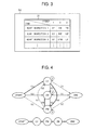
- Figure 3 is a diagram for explaining a database function of item sets for inspection in the combining and storing section 5d of Figure 2 .
- the combining and storing section 5d is also a storing section of item sets for inspection, functioning as a database of the item sets for inspection.
- item sets for inspection which underwent inspection and implementation in the past are stored.
- the item sets for inspection are registered in a database of item sets for inspection in association with medical departments and genders and disease information of the objects 2.
- routine inspection in a cardiovascular department is presented as an example.
- a table 31 shown in Figure 3 is stored.
- the table 31 presents two axes for which items in the vertical direction are defined as kinds of inspection (simplified as a kind in Figure 3 ) and items in the horizontal direction as orders of items for inspection (simplified as an order in Figure 3 ).
- the kind employs "heart inspection 1", “heart inspection 2” and “heart inspection 3", and the order indicates that items for inspection are implemented in ascending order of the numbers.
- the items for inspection are represented by alphabetical abbreviations with two characters or three characters. Meanings of the alphabetical abbreviations are as follows.
- EF means measurement of a cardiac ejection fraction of the heart of the object.
- PW means imaging the heart of the object using a pulse Doppler method.
- TDI is an abbreviation of Tissue Doppler Imaging and means, for example, analyzing a myocardium length change of the heart of the object 2 to measure a left ventricular wall thickness change and the like.
- LV means imaging an ultrasonogram of the left ventricle of the object and measuring an LVDd (Left Ventricular end Diastolic internal diameter).
- CW means imaging the heart of the object using a continuous wave Doppler method.
- CFM means imaging the heart of the object as a color flow mapping image.
- the displaying section 6 displays the table 31 when selecting implementation of "heart inspection 2".
- the displaying section 6 is one which displays the image formed by the ultrasonogram forming section 5 as an ultrasonogram, and includes, for example, a CRT monitor, a liquid crystal monitor or the like.
- the controlling section 7 is one which controls operation of the individual constituents under the instructions from a console 8, and is configured of a computer system for control which has an interface to a user interface circuit. Specifically, the controlling section 7 controls the ultrasonic wave transmitting and receiving section 4 and the ultrasonogram forming section 5 from the interface included in the controlling section 7 and on the basis of information and the like from the interface. Moreover, it performs control of transmitting information obtained by conversion into an image in the ultrasonogram forming section 5 to the displaying section 6 and the like.
- Figure 4 is a diagram for explaining a calculation function of implementation probabilities of items for inspection according to Embodiment 1 using a Markov model.
- the controlling section 7 has, as described below, a calculation function of implementation probabilities of items for inspection by which an implementation probability of a next item for inspection with respect to a current item for inspection is calculated for each item for inspection in an item set for inspection for the past item sets for inspection stored in the database of item sets for inspection in the combining and storing section 5d.
- an implementation probability of "LV” being 0.5, an implementation probability of "PW” being 0.2 and an implementation probability of "CW” being 0.3 are stored along with the past item sets for inspection in the combining and storing section 5d.
- “LV” is selected as “first time item for inspection”
- the implementation probability of "LV” being 0.5 is a conditional probability by which the next item for inspection (first time item for inspection) is multiplied.
- first time item for inspection for a second time item for inspection, an implementation probability of "LV” being 0 ⁇ 0.5, an implementation probability of "PW” being 0.6 ⁇ 0.5 and an implementation probability of "CW” being 0.3 ⁇ 0.5 are stored along with the past item sets for inspection in the combining and storing section 5d.
- PW is selected as “second time item for inspection”
- the implementation probability of "PW” being 0.7 ⁇ 0.5 is a conditional probability by which the next item for inspection (second time item for inspection) is multiplied.
- an implementation probability of "LV” being 0.1 ⁇ 0.7 ⁇ 0.5, an implementation probability of "PW” being 0 and an implementation probability of "CW” being 0.9 ⁇ 0.7 ⁇ 0.5 are stored along with the past item sets for inspection in the combining and storing section 5d.
- "CW” is selected as “third time item for inspection”
- the implementation probability of "CW” being 0.9 ⁇ 0.7 ⁇ 0.5 is a conditional probability by which the next item for inspection (inspection end) is multiplied.
- an implementation probability of "LV” being 0.2, an implementation probability of "PW” being 0.3, an implementation probability of "CW” being 0 and an implementation probability of "inspection end” being 0.5 are stored along with the past item sets for inspection in the combining and storing section 5d.
- “inspection end” is selected, and an implementation probability 0.5x0.9x0.7x0.5 is an overall probability of processing of "inspection start” to "LV” to "PW” to "CW” to "inspection end” in "heart inspection 2".
- the controlling section 7 causes the combining and storing section 5d to store the calculated implementation probabilities of the individual next items for inspection.
- Figure 5 is a diagram for explaining that a next item for inspection is displayed in a displaying region of the displaying section 6 in which the ultrasonogram is not displayed.
- the controlling section 7 presents the item set for inspection selected as mentioned above, and furthermore, presents items for inspection for which the implementation probability of a next item for inspection is present as next items for inspection.
- a method of the presentation as described in Figure 5 , in order to prevent overlapping with a region 52 of the displaying section 6 in which the ultrasonogram is displayed, they are displayed, for example, in descending order of probability in a displaying region 55 different from the region 52 in which the ultrasonogram is displayed.
- an apical four-chamber view of the heart of the object is displayed in the displaying region 52 of the ultrasonogram.
- an electrocardiogram 54 is displayed and, on the waveform of the electrocardiogram 54, a cardiac time phase bar 53 is displayed which indicates time of obtaining the apical four-chamber view, respectively.
- a displaying region 55 in which an item set for inspection and a displaying region 56 in which next items for inspection are displayed.
- Figure 6 is a flowchart for explaining an operation example according to Embodiment 1.
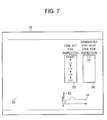
- Figure 7 is a diagram for explaining a display example of the displaying section 6 in "inspection start (START)" which is a process of operation in Figure 6 .
- the controlling section 7 generates an initial screen as shown in Figure 7 , and the initial screen is displayed on the displaying section 6.
- the portion which is described in Figure 5 is omitted and a different portion from Figure 5 is described.
- the item for inspection "START" is in the displayed state.
- the items for inspection except the item for inspection "START” are in the non-displayed state in which they are indicated by outlined characters.
- the item for inspection in the displayed state only has to be different in displaying mode such as color and blinking display from the individual items for inspection in the non-displayed state.
- the inspector inputs the item set for measurement of "heart inspection 2" using the inputting device of the inputting section 8.
- the inspector brings the ultrasonic probe 3 in contact with the chest part of the object 2 and configures a position for measuring the heart of the object 2.
- the controlling section 7 gives, to the ultrasonic wave transmitting and receiving section 4, the ultrasonogram forming section 5 and the displaying section 6, control amounts for measuring the current item for measurement "LV" which is performed upon accepting the input from the inputting device.
- controlling section 7 updates the implementation probability of the current item for inspection "inspection start” to the next item for inspection "LV” since the implementation frequency in the current item for inspection "inspection start” to the next item for inspection "LV” increases by one event.
- the implementation probability of the current item for inspection "inspection start” to the next item for inspection "LV” is 0.5
- the implementation probability of the current item for inspection "inspection start” to the next item for inspection "CW” is 0.3
- the implementation probability of the current item for inspection "inspection start” to the next item for inspection "PW” is 0.2.
- a probability in which an event is implemented next (implementation probability) and a probability in which not implemented (non-implementation probability) are represented by the following general formulae.
- Non-implementation probability the number of the relevant events in the past/(the number of the total events in the past+1)
- the implementation probability (the current item for inspection "inspection start” to the next item for inspection "LV”) is updated to 0.54, the non-implementation probabilities to 0.27 (probability for the current item for inspection “inspection start” to the next item for inspection "CW”), and to 0.18 (probability for the current item for inspection "inspection start” to the next item for inspection "PW”), respectively.
- the conditional probability for transfer of "first time item for inspection” to "second time item for inspection” is the implementation probability of the current item for inspection "inspection start” to the next item for inspection "LV” being 0.54.
- Figure 8 is a diagram for explaining a display example of the displaying section 6 in "first time item for inspection" which is a process of operation in Figure 6 .
- the portion which is described in Figure 5 is omitted and a different portion from Figure 5 is described.
- the current item for inspection LV is in the displayed state and the items for inspection except the current item for inspection LV are in the non-displayed state in which they are indicated by outlined characters, and thereby, the current item for inspection can be discriminated from the other items for inspection, these being displayed.
- the ultrasonic probe 3 converts a pulse-like electric signal which is for generating an ultrasonic signal and is transmitted from the ultrasonic wave transmitting and receiving section 4 into an ultrasonic wave to transmit it to the object 2, receives the echo signal reflected from the object 2, converts the received echo signal to an electric signal, and returns it to the ultrasonic wave transmitting and receiving section 4.
- the ultrasonic wave transmitting and receiving section 4 performs signal processing on the electric signal obtained by the conversion of the echo signal received by the ultrasonic probe 3.
- the ultrasonogram forming section 5 forms a two-dimensional ultrasonogram from the electric signal having undergone the signal processing.
- the displaying section 6 displays the ultrasonogram formed by the ultrasonogram forming section 5.
- the inspector measures, using the inputting device, the left ventricular internal diameter on the ultrasonogram displayed on the displaying section 6 by means of known distance measurement, referring to the electrocardiogram 54, and the measurement value is displayed in a displaying region 59 of the displaying section 6.
- the left ventricular internal diameter as the measurement object, the region, called lumen, in which blood is filled is separated from the region of the myocardium which covers the lumen region, and difference between the region of the lumen and the region of the myocardium in grayscale of the image is clear. Therefore, the left ventricular internal diameter is always being measured, and the measurement value only at the end diastolic in the electrocardiogram is displayed in the displaying region 59 of the displaying section 6.
- Step S104 LV to PW
- the controlling section 7 determines the presence or absence of a next item for inspection. In this case, since the next item for inspection "PW" of the current item for inspection "LV” is present, the controlling section 7 performs branching to the presence of a next item for inspection, that is, "y" and moves to step S105.
- the controlling section 7 reads out the next item for inspection "PW” and the implementation probability of "PW” being 0.7x0.5 from the combining and storing section 5d, and displays the next item for inspection "PW” in the displaying region 56.
- the controlling section 7 updates the implementation probability of the current item for inspection "LV” to the next item for inspection "PW".
- the implementation probability of the current item for inspection "LV” to the next item for inspection "PW” is 0.6
- the implementation probability of the current item for inspection "LV” to the next item for inspection "CW” is 0.3
- the implementation probability of the current item for inspection "LV” to the next item for inspection "END” is 0.1. It is supposed that the basis of these probability calculations is in that, out of 10 times of events, the current item for inspection "LV” to the next item for inspection "PW” is 6 times, that the current item for inspection "LV” to the next item for inspection "CW” is 3 times, and that the current item for inspection "LV” to the next item for inspection "END” is 1 time.
- conditional probability for transfer of "second time item for inspection” to "third time item for inspection” is the implementation probability of the current item for inspection "LV” to the next item for inspection "PW” being 0.64 ⁇ 0.54.
- the controlling section 7 Upon change of the implementation frequency in the current item for inspection "LV” to the next item for inspection "PW", the controlling section 7 recalculates the implementation probabilities of the current item for inspection "LV” to the next item for inspection "PW", the current item for inspection "LV” to the next item for inspection "CW”, and the current item for inspection "LV” to the next item for inspection "END”, respectively, and stores the individual calculated implementation probabilities in the combining and storing section 5d.
- the controlling section 7 replaces the next item for inspection "PW" for the current item for inspection, and moves to step S103.
- the controlling section 7 gives, to the ultrasonic wave transmitting and receiving section 4, the ultrasonogram forming section 5 and the displaying section 6, control amounts for measuring the current item for measurement "PW" which is performed upon accepting the input from the inputting device.
- Figure 9 is a diagram for explaining a display example of the displaying section 6 in "second time item for inspection" which is a process of operation in Figure 6 .
- the portion which is described in Figure 5 is omitted and a different portion from Figure 5 is described.
- the current item for inspection PW is in the displayed state and the items for inspection except the current item for inspection PW are in the non-displayed state in which they are indicated by outlined characters, and thereby, the current item for inspection can be discriminated from the other items for inspection, these being displayed.
- the ultrasonogram forming section 5 forms a Doppler spectrum due to pulse Doppler from the electric signal having undergone the signal processing.
- the displaying section 6 displays the Doppler spectrum due to pulse Doppler formed by the ultrasonogram forming section 5 in the displaying region 52.
- the inspector can perform selection and input arbitrary from the displayed candidates for the next item for inspection at this stage, the selection and input is not supposed to be performed in this case.
- the controlling section 7 determines the presence or absence of a next item for inspection in the item set for inspection. In this case, since the next item for inspection "CW" of the current item for inspection "PW” is present, the controlling section 7 performs branching to the presence of a next item for inspection, that is, "y" and moves to step S105.
- the controlling section 7 reads out the next item for inspection "CW" from the combining and storing section 5d, and displays it in the displaying region 56.
- the implementation probability of the current item for inspection "PW” to the next item for inspection "CW” is to be updated similarly to step S106: LV.
- the controlling section 7 updates the implementation probability of the current item for inspection "PW” to the next item for inspection "CW”.
- the implementation probability of the current item for inspection "PW” to the next item for inspection "CW” is 0.9
- the implementation probability of the current item for inspection "PW” to the next item for inspection "LV” is 0.1
- the implementation probability of the current item for inspection "PW” to the next item for inspection "END” is 0.3. It is supposed that the basis of these probability calculations is in that, out of 10 times of events, the current item for inspection "PW” to the next item for inspection "CW” is 9 times, that the current item for inspection "PW” to the next item for inspection "LV” is 1 time, and that the current item for inspection "PW” to the next item for inspection "END” is 3 times.
- the controlling section 7 Upon change of the implementation frequency in the current item for inspection "PW” to the next item for inspection "CW”, the controlling section 7 recalculates the implementation probabilities of the current item for inspection "PW” to the next item for inspection "CW", the current item for inspection "PW” to the next item for inspection "LV”, and the current item for inspection "PW” to the next item for inspection "END”, respectively, and stores the individual implementation probabilities in the combining and storing section 5d.
- the controlling section 7 replaces the next item for inspection "CW" for the current item for inspection, and moves to step S103.
- the controlling section 7 gives, to the ultrasonic wave transmitting and receiving section 4, the ultrasonogram forming section 5 and the displaying section 6, control amounts for measuring the current item for measurement "CW" which is performed upon accepting the input from the inputting device.
- Figure 10 is a diagram for explaining as a display example of the displaying section 6 in "third time item for inspection" which is a process of operation in Figure 6 .
- the portion which is described in Figure 5 is omitted and a different portion from Figure 5 is described.
- the current item for inspection CW is in the displayed state and the items for inspection except the current item for inspection CW are in the non-displayed state in which they are indicated by outlined characters, and thereby, the current item for inspection can be discriminated from the other items for inspection, these being displayed.
- the ultrasonogram forming section 5 forms a Doppler spectrum due to continuous wave Doppler from the electric signal having undergone the signal processing.
- the displaying section 6 displays the Doppler spectrum due to continuous wave Doppler formed by the ultrasonogram forming section 5 in the displaying region 52.
- the merit of "PW” is that it has distance resolution. Instead, the restricting conditions of the maximum detection frequency and the maximum detection depth arise, not arising for "CW”. On the other hand, the feature of "CW” is no practical measurement limit in high-speed blood flow measurement. However, "CW” does not have positional resolution and the position of the generation source of a received signal cannot be known. Therefore, both of "PW” and “CW” are performed in order to complement the demerits of both of "PW” and "CW”.
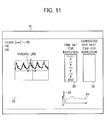
- the controlling section 7 determines the presence or absence of a next item for inspection. In this case, since a next item for inspection "END" of the current item for inspection "CW" is not present, the controlling section 7 performs branching to the absence of a next item for inspection, that is, "n" and moves to step S108. An example of movement to step S108 is shown in Figure 11 as a display example.
- END may be displayed in the displaying region 56 in order to clarify the end of the processing.
- Figure 11 is a diagram for explaining a display example of the displaying section 6 in "inspection end (END)" which is a process of operation in Figure 6 .
- the inspector inputs whether or not the position of the ultrasonic probe 3 is reconfigured to continue another item set for measurement or the like using the inputting section 8.
- controlling section 7 moves to step S102 when another item set for measurement or the like is continued or moves to step S109 when reconfiguration is not performed.
- the inspector inputs whether or not the measurement is ended using the inputting section 8.
- the controlling section 7 moves to END when the measurement is ended or moves to step S101 when the measurement is not ended.
- Embodiment 1 since a plurality of items for inspection including ultrasonic imaging or measurement of an imaged ultrasonogram and an order thereof are stored, regarding an item set for inspection constituted of a next item for inspection which is an item for inspection subsequent to a current item for inspection currently being implemented out of the plurality of items for inspection, an implementation frequency at which the item set for inspection is implemented, for each next item for inspection is calculated, an implementation probability in which the item set for inspection is implemented is calculated by calculating a non-implementation frequency for each next item for inspection for which the item set for inspection has not been sequentially implemented and an overall frequency obtained by adding the implementation frequency and the non-implementation frequency and by dividing the implementation frequency by the overall frequency, a candidate for the next item for inspection on the basis of the implementation frequency is displayed, and the next item for inspection from the candidate for the next item for inspection is inputted, operability in selecting a plurality of items for inspection subsequent after the current item for inspection in an item set for inspection can be improved.
- Embodiment 2 is described using figures.
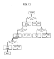
- a different point from Embodiment 1 is in the case of using a decision tree in Figure 12 in place of the Markov model in Figure 4 .
- Embodiment 2 Since the configuration of the ultrasonic diagnosis apparatus is described in Embodiment 1 using Figure 1 , its description is omitted in Embodiment 2.
- the configuration of the ultrasonogram forming section 5 in the ultrasonic diagnosis apparatus while one stored in the combining and storing section 5d in Embodiment 1 is the Markov model shown in Figure 4 , that in Embodiment 2 is the decision tree shown in Figure 12 , this being the difference. Except the above-mentioned difference, the description of the configuration of the ultrasonogram forming section 5 is omitted in Embodiment 2.
- a method of the presentation may employ, for example, a descending order of frequency.
- Figure 12 is a diagram for explaining a calculation function of implementation frequencies of items for inspection using the decision tree according to Embodiment 2.
- the controlling section 7 has a calculation function of implementation frequencies of items for inspection by which an implementation frequency of a next item for inspection with respect to a current item for inspection is calculated for each item for inspection in an item set for inspection for the past item sets for inspection stored in the database of item sets for inspection in the combining and storing section 5d.
- a frequency of using "LV” being 51 and a frequency of not using being 50 are stored for a next item for inspection (first time item for inspection) in the combining and storing section 5d, respectively.
- first time item for inspection a next item for inspection
- using "LV” for "first time item for inspection” is selected. Due to this selection, the frequency of using "LV” for "first time item for inspection” increases to 52.
- a frequency of using "CW” being 30 and a frequency of not using “CW” being 15 are stored in the combining and storing section 5d, respectively.
- using "CW” for "third time item for inspection” is selected. Due to this selection, the frequency of using "CW” for "third time item for inspection” increases to 31.
- the controlling section 7 causes the combining and storing section 5d to store the implementation frequencies of the individual calculated next items for inspection.
- Embodiment 2 since the display of the next item for inspection is same as that described in Embodiment 1 using Figure 5 , the description in Embodiment 2 is omitted.
- Figure 13 is a flowchart for explaining an operation example according to Embodiment 2.
- Embodiment 1 using Figure 6 to Figure 11 applies as being same, and therefore, the description is omitted in Embodiment 2.
- the implementation probability is calculated in Embodiment 1, the item for inspection in step S106 being an event, the implementation frequency is calculated in Embodiment 2, the item for inspection in step S110 being an event.
- the implementation frequency in the current item for inspection "LV” to the next item for inspection "PW” is to be updated since the implementation frequency in the current item for inspection "LV” to the next item for inspection "PW” increases by one event.
- the controlling section 7 Upon change of the implementation frequency in the current item for inspection "LV” to the next item for inspection "PW", the controlling section 7 recalculates the implementation frequencies in the current item for inspection "LV” to the next item for inspection "PW", the current item for inspection "LV” to the next item for inspection "CW”, and the current item for inspection "LV” to the next item for inspection "END”, respectively, and stores the individual calculated implementation frequencies in the combining and storing section 5d.
- the implementation frequency in the current item for inspection "PW” to the next item for inspection "CW” is to be updated similarly to step S106: LV since the implementation frequency in the current item for inspection "PW” to the next item for inspection "CW” increases by one event.
- the controlling section 7 Upon change of the implementation frequency in the current item for inspection "PW” to the next item for inspection "CW”, the controlling section 7 recalculates the implementation frequencies in the current item for inspection "PW” to the next item for inspection "CW”, the current item for inspection "PW” to the next item for inspection "LV”, and the current item for inspection "PW” to the next item for inspection "END”, respectively, and stores the individual calculated implementation frequencies in the combining and storing section 5d.
- Embodiment 2 by including a storing section storing a plurality of items for inspection including ultrasonic imaging or measurement of an imaged ultrasonogram and an order thereof, a controlling section calculating, regarding an item set for inspection constituted of a next item for inspection which is an item for inspection subsequent to a current item for inspection which is currently being implemented out of the plurality of items for inspection, an implementation frequency at which the item set for inspection is implemented, for each next item for inspection, a displaying section displaying a candidate for the next item for inspection on the basis of the implementation frequency, and an inputting section inputting the next item for inspection out of the candidate for the next item for inspection, operability in selecting a plurality of items for inspection subsequent after the current item for inspection in an item set for inspection can be improved.
- Embodiment 2 compared with the calculation of implementation probabilities in Embodiment 1, only the calculation of implementation frequencies is required, and therefore, any circuit or program for point operations is not required and the circuit configuration and programming can be simplified.
- Embodiment 3 is described using figures.
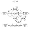
- a different point from Embodiment 1 is in the case of changing in the midway of an item set for measurement for the Markov model in Figure 4 , as shown in Figure 14 .
- Embodiment 2 Since the configuration of the ultrasonic diagnosis apparatus is described in Embodiment 1 using Figure 1 and Figure 2 , its description is omitted in Embodiment 2.
- Figure 14 is a diagram for explaining a calculation function of implementation probabilities of items for inspection using a Markov model according to Embodiment 3.
- the controlling section 7 causes the combining and storing section 5d to store the implementation probabilities of the individual calculated next items for inspection.
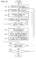
- Figure 15 is a flowchart for explaining an operation example according to Embodiment 3.
- Embodiment 1 using Figure 6 to Figure 11 applies as being same, and therefore, the description is omitted in Embodiment 3.
- step S111 as follows is added between step S103 and step S104.
- the inspector inputs change of the item for measurement.
- the controlling section 7 changes part of the items for measurement in the item set for measurement.
- "third time item for inspection” is changed from “CW” to "TDI”.
- Figure 16 is a diagram for explaining a display example of the displaying section 6 in "third time item for inspection" which is one process of operation in Figure 15 .
- the controlling section 7 Upon the change of the implementation frequency of the current item for inspection "TDI", the controlling section 7 recalculates the implementation frequencies of the current item for inspection "LV” to the next item for inspection "PW", the current item for inspection "LV” to the next item for inspection "CW”, and the current item for inspection "LV” to the next item for inspection "END”, respectively, and stores individual calculated implementation probabilities in the combining and storing section 5d.
- Embodiment 3 similarly to Embodiment 1, operability in selecting a plurality of items for inspection subsequent after a current item for inspection in an item set for inspection can be improved. In other words, since part of the item set for measurement according to Embodiment 1 can be changed, flexibility of items for measurement can be improved, not fixing the only items for measurement.
- Embodiment 3 since the operations of the individual items for inspection can be confirmed in an item set for inspection, reliability of the operations of the individual items for inspection can be improved.
- Embodiment 3 is described using implementation probabilities of items for measurement, whereas it may be done using implementation frequencies of items for measurement described in Embodiment 2.
- ultrasonic diagnosis apparatus 3: ultrasonic probe
- 4 ultrasonic wave transmitting and receiving section
- 5 ultrasonogram forming section
- 5a ultrasonogram information generating section
- 5b digital scan converter (DSC) section
- 5c graphic data generating section
- 5d combining and storing section
- 5e interface
- 6 displaying section
- 7 controlling section
- 8 inputting section
Landscapes
- Health & Medical Sciences (AREA)
- Life Sciences & Earth Sciences (AREA)
- Engineering & Computer Science (AREA)
- Public Health (AREA)
- Medical Informatics (AREA)
- Biomedical Technology (AREA)
- General Health & Medical Sciences (AREA)
- Pathology (AREA)
- Surgery (AREA)
- Biophysics (AREA)
- Radiology & Medical Imaging (AREA)
- Molecular Biology (AREA)
- Physics & Mathematics (AREA)
- Animal Behavior & Ethology (AREA)
- Nuclear Medicine, Radiotherapy & Molecular Imaging (AREA)
- Heart & Thoracic Surgery (AREA)
- Veterinary Medicine (AREA)
- Physiology (AREA)
- Computer Vision & Pattern Recognition (AREA)
- Data Mining & Analysis (AREA)
- Databases & Information Systems (AREA)
- Epidemiology (AREA)
- Primary Health Care (AREA)
- Ultra Sonic Daignosis Equipment (AREA)
Abstract
Description
- The present invention relates to an ultrasonic diagnosis apparatus and a method for presenting items for inspection in the same for presenting, to the inspector, a plurality of candidates for an item for inspection (referred to as next item for inspection) next to an item for inspection currently being implemented (referred to as current item for inspection).
- In an ultrasonic diagnosis apparatus, a plurality of kinds of items for inspection are performed as routine inspection for each medical department or each disease, the plurality of kinds of items for inspection being done in specific orders, and constitute a plurality of kinds of sets of items for inspection performed in these orders (referred to as item sets for inspection). Regarding the item sets for inspection,
Patent Literature 1 discloses the following steps. -
- Step 1: step of accumulating usage counts of the past item sets for inspection
- Step 2: step of registering, when the accumulated usage count of an item set for inspection reaches a defined number, it as an "item set for inspection whose usage count reaches the defined number"
- Step 3: step of selecting a standard item set for inspection out of the registered "item sets for inspection whose usage counts reach the defined number"
- Step 4: step of registering the selected item set for inspection in a recording section
-
- Patent Literature 1:
JP-A-2009-77960 - In
Patent Literature 1, since one item set for inspection which is registered in the recording section is provided, it is considered that a view point of improvement of operability when an item for inspection different from the next item for inspection registered in the relevant item set for inspection is wanted to be implemented after implementing the current item for inspection has not been investigated. - Therefore, an object of the present invention is to provide an ultrasonic diagnosis apparatus and a method for presenting items for inspection in the same capable of improving operability in selecting a next item for inspection after a current item for inspection in an item set for inspection.
- To achieve the above-mentioned object, the present invention stores a plurality of items for inspection including ultrasonic imaging or measurement of an imaged ultrasonogram and an order thereof, calculates, regarding an item set for inspection constituted of a current item for inspection which is currently being implemented and a next item for inspection which is an item for inspection subsequent to the relevant current item for inspection out of the plurality of items for inspection, an implementation frequency at which the item set for inspection is implemented, for each next item for inspection, displays a candidate for the next item for inspection on the basis of the implementation frequency, and inputs the next item for inspection from the candidate for the next item for inspection.
- According to the present invention, operability in selecting a next item for inspection after a current item for inspection in an item set for inspection can be improved.
-
- [
Figure 1] Figure 1 is a block diagram showing an exemplary configuration of an ultrasonic diagnosis apparatus to which the present invention is applied. - [
Figure 2] Figure 2 is a block diagram showing an exemplary configuration of anultrasonogram forming section 5 inFigure 1 . - [
Figure 3] Figure 3 is a diagram for explaining of a function of database of item sets for inspection in a combining and storingsection 5d inFigure 2 . - [
Figure 4] Figure 4 is a diagram for explaining a calculation function of implementation probabilities of items for inspection according toEmbodiment 1 using a Markov model. - [
Figure 5] Figure 5 is a diagram for explaining display of candidates for a next item for inspection in a displayingregion 56 of a displayingsection 6 inFigure 1 . - [
Figure 6] Figure 6 is a flowchart for explaining an operation example according toEmbodiment 1. - [
Figure 7] Figure 7 is a diagram for explaining a display example of the displayingsection 6 in "inspection start (START)" which is one process of operation inFigure 6 . - [
Figure 8] Figure 8 is a diagram for explaining a display example of the displayingsection 6 in "first time item for inspection" which is one process of operation inFigure 6 . - [
Figure 9] Figure 9 is a diagram for explaining a display example of the displayingsection 6 in "second time item for inspection" which is one process of operation inFigure 6 . - [
Figure 10] Figure 10 is a diagram for explaining a display example of the displayingsection 6 in "third time item for inspection" which is one process on operation inFigure 6 . - [
Figure 11] Figure 11 is a diagram for explaining a display example of the displayingsection 6 in "inspection end (END)" which is one process on operation inFigure 6 . - [
Figure 12] Figure 12 is a diagram for explaining a calculation function of implementation probabilities of items for inspection using a decision tree according toEmbodiment 2. - [
Figure 13] Figure 13 is a flowchart for explaining an operation example according toEmbodiment 2. - [
Figure 14] Figure 14 is a diagram for explaining a calculation function of implementation probabilities of items for inspection using a Markov model according toEmbodiment 3. - [
Figure 15] Figure 15 is a flowchart for explaining an operation example according toEmbodiment 3. - [
Figure 16] Figure 16 is a diagram for explaining a display example of the displayingsection 6 in "third time item for inspection" which is one process of operation inFigure 15 . - Embodiments for implementing the invention are described as follows.
- In
Embodiment 1, a method for presenting candidates for a next item for inspection using a Markov model is described. An ultrasonic diagnosis apparatus adopted inEmbodiment 1 is described in detail using figures.Figure 1 is a block diagram showing a configuration of an ultrasonic diagnosis apparatus to which the present invention is applied. - An
ultrasonic diagnosis apparatus 1 shown inFigure 1 is one which configures and displays a two-dimensional ultrasonogram, a three-dimensional ultrasonogram or various kinds of Doppler images of a diagnosis portion using an echo signal obtained by transmitting and receiving an ultrasonic wave into aobject 2, and includes constituents of anultrasonic probe 3, an ultrasonic wave transmitting and receivingsection 4, anultrasonogram forming section 5, a displayingsection 6, a controllingsection 7 and aninputting section 8. - The
ultrasonic probe 3 is one which receives a reflected echo after transmitting an ultrasonic wave to theobject 2, and is constituted of a plurality of oscillation elements which are arranged for 1 to m channels in a longitudinal axis direction. The ultrasonic wave transmitting and receivingsection 4 is one which generates a pulse-like electric signal for generating an ultrasonic signal transmitted to theobject 2 and transmits this to theultrasonic probe 3, and in addition, which performs signal processing on an electric signal obtained by converting the echo signal received by theultrasonic probe 3. Theultrasonogram forming section 5 is one which forms various kinds of ultrasonograms including a two-dimensional ultrasonogram, a three-dimensional ultrasonogram or a Doppler image from the electric signal having undergone the signal processing. The displayingsection 6 is one which displays the ultrasonogram formed by theultrasonogram forming section 5. The controllingsection 7 is one which controls the individual elements of the ultrasonic wave transmitting and receivingsection 4, theultrasonogram forming section 5 and the displayingsection 6. Theinputting section 8 is one which gives, to the controllingsection 7, inputted instructions, the inspector inputting the instructions to the individual elements via an inputting device such as a keyboard and a pointing device attached to theinputting section 8 itself. -
Figure 2 is a block diagram showing an exemplary configuration of theultrasonogram forming section 5 inFigure 1 . - The
ultrasonogram forming section 5 shown inFigure 2 includes constituents of an ultrasonograminformation generating section 5a, a digital scan converter section (referred to as DSC section; Digital Scan Converter) 5b, a graphicdata generating section 5c, a combining and storingsection 5d and aninterface 5e. - The ultrasonogram
information generating section 5a is one which generates ultrasonogram information of the inspection object using the echo signal undergoing the signal processing. TheDSC section 5b is one which scans and converts the ultrasonogram information generated by the ultrasonograminformation generating section 5a into a television display image pattern to generate ultrasonogram data. The graphicdata generating section 5c is one which generates graphic data such as scales, marks and characters to be attached to an image which is based on image data obtained by the scanning and conversion of theDSC section 5b. The combining and storingsection 5d is one which combines and stores the ultrasonogram data generated by theDSC section 5b and the graphic data generated by the graphicdata generating section 5c, and has a hard disk, a temporary storage memory RAM and the like. Theinterface 5e is an interface of theultrasonogram forming section 5 for reading out, from the controllingsection 7 under the control of the controllingsection 7, initial values, control parameters and the like required for various kinds of processing of the ultrasonograminformation generating section 5a which generates the ultrasonogram information, theDSC section 5b, the graphicdata generating section 5c and the combining and storingsection 5d to configure them to the ultrasonograminformation generating section 5a, theDSC section 5b, the graphicdata generating section 5c and the combining and storingsection 5d. -
Figure 3 is a diagram for explaining a database function of item sets for inspection in the combining and storingsection 5d ofFigure 2 . - The combining and storing
section 5d is also a storing section of item sets for inspection, functioning as a database of the item sets for inspection. In the database of item sets for inspection, item sets for inspection which underwent inspection and implementation in the past are stored. The item sets for inspection are registered in a database of item sets for inspection in association with medical departments and genders and disease information of theobjects 2. Herein, routine inspection in a cardiovascular department is presented as an example. In the combining and storingsection 5d, a table 31 shown inFigure 3 is stored. The table 31 presents two axes for which items in the vertical direction are defined as kinds of inspection (simplified as a kind inFigure 3 ) and items in the horizontal direction as orders of items for inspection (simplified as an order inFigure 3 ). The kind employs "heart inspection 1", "heart inspection 2" and "heart inspection 3", and the order indicates that items for inspection are implemented in ascending order of the numbers. The items for inspection are represented by alphabetical abbreviations with two characters or three characters. Meanings of the alphabetical abbreviations are as follows. "EF" means measurement of a cardiac ejection fraction of the heart of the object. "PW" means imaging the heart of the object using a pulse Doppler method. "TDI" is an abbreviation of Tissue Doppler Imaging and means, for example, analyzing a myocardium length change of the heart of theobject 2 to measure a left ventricular wall thickness change and the like. "LV" means imaging an ultrasonogram of the left ventricle of the object and measuring an LVDd (Left Ventricular end Diastolic internal diameter). "CW" means imaging the heart of the object using a continuous wave Doppler method. "CFM" means imaging the heart of the object as a color flow mapping image. - Thus, in the table 31, "EF" to "PW" to "TDI" in "
heart inspection 1", "LV" to "PW" to "CW" in "heart inspection 2", and "EF" to "CFM" to "PV" in "heart inspection 3" are stored as item sets for inspection for cardiac surgery. The inspector inputs that the inspector implements "heart inspection 2" using the inputting device prepared in theinputting section 8. - The displaying
section 6 displays the table 31 when selecting implementation of "heart inspection 2". - The displaying
section 6 is one which displays the image formed by theultrasonogram forming section 5 as an ultrasonogram, and includes, for example, a CRT monitor, a liquid crystal monitor or the like. - The controlling
section 7 is one which controls operation of the individual constituents under the instructions from aconsole 8, and is configured of a computer system for control which has an interface to a user interface circuit. Specifically, the controllingsection 7 controls the ultrasonic wave transmitting and receivingsection 4 and theultrasonogram forming section 5 from the interface included in the controllingsection 7 and on the basis of information and the like from the interface. Moreover, it performs control of transmitting information obtained by conversion into an image in theultrasonogram forming section 5 to the displayingsection 6 and the like. -
Figure 4 is a diagram for explaining a calculation function of implementation probabilities of items for inspection according toEmbodiment 1 using a Markov model. - The controlling
section 7 has, as described below, a calculation function of implementation probabilities of items for inspection by which an implementation probability of a next item for inspection with respect to a current item for inspection is calculated for each item for inspection in an item set for inspection for the past item sets for inspection stored in the database of item sets for inspection in the combining andstoring section 5d. - A calculation function of implementation probabilities of items for inspection shown in
Figure 4 is described using an example of transition of "inspection start" to "LV" to "PW" to "CW" to "inspection end" in "heart inspection 2". - First, in "inspection start", for a next item for inspection (first time item for inspection), an implementation probability of "LV" being 0.5, an implementation probability of "PW" being 0.2 and an implementation probability of "CW" being 0.3 are stored along with the past item sets for inspection in the combining and
storing section 5d. Herein, as indicated by a bold arrow in the figure, "LV" is selected as "first time item for inspection", and the implementation probability of "LV" being 0.5 is a conditional probability by which the next item for inspection (first time item for inspection) is multiplied. - Next, in "first time item for inspection", for a second time item for inspection, an implementation probability of "LV" being 0×0.5, an implementation probability of "PW" being 0.6×0.5 and an implementation probability of "CW" being 0.3×0.5 are stored along with the past item sets for inspection in the combining and
storing section 5d. Herein, as indicated by a bold arrow in the figure, "PW" is selected as "second time item for inspection", and the implementation probability of "PW" being 0.7×0.5 is a conditional probability by which the next item for inspection (second time item for inspection) is multiplied. - Next, in "second time item for inspection", for a third time item for inspection, an implementation probability of "LV" being 0.1×0.7×0.5, an implementation probability of "PW" being 0 and an implementation probability of "CW" being 0.9×0.7×0.5 are stored along with the past item sets for inspection in the combining and
storing section 5d. Herein, as indicated by a bold arrow in the figure, "CW" is selected as "third time item for inspection", and the implementation probability of "CW" being 0.9×0.7×0.5 is a conditional probability by which the next item for inspection (inspection end) is multiplied. - Finally, in "third item for inspection", for an inspection end, an implementation probability of "LV" being 0.2, an implementation probability of "PW" being 0.3, an implementation probability of "CW" being 0 and an implementation probability of "inspection end" being 0.5 are stored along with the past item sets for inspection in the combining and
storing section 5d. Herein, as indicated by a bold arrow in the figure, "inspection end" is selected, and an implementation probability 0.5x0.9x0.7x0.5 is an overall probability of processing of "inspection start" to "LV" to "PW" to "CW" to "inspection end" in "heart inspection 2". - The controlling
section 7 causes the combining andstoring section 5d to store the calculated implementation probabilities of the individual next items for inspection. -
Figure 5 is a diagram for explaining that a next item for inspection is displayed in a displaying region of the displayingsection 6 in which the ultrasonogram is not displayed. - The controlling
section 7 presents the item set for inspection selected as mentioned above, and furthermore, presents items for inspection for which the implementation probability of a next item for inspection is present as next items for inspection. As a method of the presentation, as described inFigure 5 , in order to prevent overlapping with aregion 52 of the displayingsection 6 in which the ultrasonogram is displayed, they are displayed, for example, in descending order of probability in a displayingregion 55 different from theregion 52 in which the ultrasonogram is displayed. - On a
screen 51 of the displayingsection 6 inFigure 5 , an apical four-chamber view of the heart of the object is displayed in the displayingregion 52 of the ultrasonogram. Moreover, in the lower right to the displayingregion 52 on thescreen 51 of the displayingsection 6, anelectrocardiogram 54 is displayed and, on the waveform of theelectrocardiogram 54, a cardiactime phase bar 53 is displayed which indicates time of obtaining the apical four-chamber view, respectively. Moreover, in the upper right to the displayingregion 52 on thescreen 51 of the displayingsection 6, a displayingregion 55 in which an item set for inspection and a displayingregion 56 in which next items for inspection are displayed. - Next, a procedure of implementing "
heart inspection 2" out of item sets for inspection is described usingFigure 6 to Figure 11 .Figure 6 is a flowchart for explaining an operation example according toEmbodiment 1.Figure 7 is a diagram for explaining a display example of the displayingsection 6 in "inspection start (START)" which is a process of operation inFigure 6 . - The controlling
section 7 generates an initial screen as shown inFigure 7 , and the initial screen is displayed on the displayingsection 6. As to the individual signs inFigure 7 , the portion which is described inFigure 5 is omitted and a different portion fromFigure 5 is described. In the displayingregion 55 of the item set for inspection inFigure 7 , the item for inspection "START" is in the displayed state. Moreover, the items for inspection except the item for inspection "START" are in the non-displayed state in which they are indicated by outlined characters. In addition, the item for inspection in the displayed state only has to be different in displaying mode such as color and blinking display from the individual items for inspection in the non-displayed state. As above, by setting the current item for inspection in the displayed state in which it only be made conspicuous, since the current item for inspection can be clearly discriminated from the next item for inspection, items for inspection which have been already implemented, and the like, the inspector can quickly recognize progress of the item set for inspection. - The inspector inputs the item set for measurement of "
heart inspection 2" using the inputting device of theinputting section 8. - The inspector brings the
ultrasonic probe 3 in contact with the chest part of theobject 2 and configures a position for measuring the heart of theobject 2. - The controlling
section 7 gives, to the ultrasonic wave transmitting and receivingsection 4, theultrasonogram forming section 5 and the displayingsection 6, control amounts for measuring the current item for measurement "LV" which is performed upon accepting the input from the inputting device. - Moreover, the controlling
section 7 updates the implementation probability of the current item for inspection "inspection start" to the next item for inspection "LV" since the implementation frequency in the current item for inspection "inspection start" to the next item for inspection "LV" increases by one event. - For example, as shown in
Figure 4 , the implementation probability of the current item for inspection "inspection start" to the next item for inspection "LV" is 0.5, the implementation probability of the current item for inspection "inspection start" to the next item for inspection "CW" is 0.3, and the implementation probability of the current item for inspection "inspection start" to the next item for inspection "PW" is 0.2. - A probability in which an event is implemented next (implementation probability) and a probability in which not implemented (non-implementation probability) are represented by the following general formulae.
- Implementation probability=the number of the relevant events in the past+1/(the number of the total events in the past+1)
- Non-implementation probability=the number of the relevant events in the past/(the number of the total events in the past+1)
- The basis for these probability calculations are described as follows. First, it is supposed that the number of the total events in the past is 10 times and the number of the relevant events in the past is 5 times in the current item for inspection "inspection start" to the next item for inspection "LV", that the number of the relevant events in the past is 3 times in the current item for inspection "inspection start" to the next item for inspection "CW", and that the number of the relevant events in the past is 2 times in the current item for inspection "inspection start" to the next item for inspection "PW". It is supposed that, this time, the number of the total events is 11 times and an event in the current item for inspection "inspection start" to the next item for inspection "LV" arises. The implementation probability (the current item for inspection "inspection start" to the next item for inspection "LV") is updated to 0.54, the non-implementation probabilities to 0.27 (probability for the current item for inspection "inspection start" to the next item for inspection "CW"), and to 0.18 (probability for the current item for inspection "inspection start" to the next item for inspection "PW"), respectively. Moreover, the conditional probability for transfer of "first time item for inspection" to "second time item for inspection" is the implementation probability of the current item for inspection "inspection start" to the next item for inspection "LV" being 0.54.
- Thereby, the displayed state of the displaying
section 6 is moved fromFigure 7 to Figure 8 . -
Figure 8 is a diagram for explaining a display example of the displayingsection 6 in "first time item for inspection" which is a process of operation inFigure 6 . As to the individual signs inFigure 8 , the portion which is described inFigure 5 is omitted and a different portion fromFigure 5 is described. In the displayingregion 55 of the item set for inspection inFigure 8 , the current item for inspection LV is in the displayed state and the items for inspection except the current item for inspection LV are in the non-displayed state in which they are indicated by outlined characters, and thereby, the current item for inspection can be discriminated from the other items for inspection, these being displayed. - The
ultrasonic probe 3 converts a pulse-like electric signal which is for generating an ultrasonic signal and is transmitted from the ultrasonic wave transmitting and receivingsection 4 into an ultrasonic wave to transmit it to theobject 2, receives the echo signal reflected from theobject 2, converts the received echo signal to an electric signal, and returns it to the ultrasonic wave transmitting and receivingsection 4. The ultrasonic wave transmitting and receivingsection 4 performs signal processing on the electric signal obtained by the conversion of the echo signal received by theultrasonic probe 3. Theultrasonogram forming section 5 forms a two-dimensional ultrasonogram from the electric signal having undergone the signal processing. The displayingsection 6 displays the ultrasonogram formed by theultrasonogram forming section 5. As to the left ventricular end diastolic internal diameter of the heart of theobject 2, the inspector measures, using the inputting device, the left ventricular internal diameter on the ultrasonogram displayed on the displayingsection 6 by means of known distance measurement, referring to theelectrocardiogram 54, and the measurement value is displayed in a displayingregion 59 of the displayingsection 6. - Moreover, in the ultrasonogram, for the left ventricular internal diameter as the measurement object, the region, called lumen, in which blood is filled is separated from the region of the myocardium which covers the lumen region, and difference between the region of the lumen and the region of the myocardium in grayscale of the image is clear. Therefore, the left ventricular internal diameter is always being measured, and the measurement value only at the end diastolic in the electrocardiogram is displayed in the displaying
region 59 of the displayingsection 6. - As above, the implementation of the current item for measurement "LV" completes.
- The controlling
section 7 determines the presence or absence of a next item for inspection. In this case, since the next item for inspection "PW" of the current item for inspection "LV" is present, the controllingsection 7 performs branching to the presence of a next item for inspection, that is, "y" and moves to step S105. - The controlling
section 7 reads out the next item for inspection "PW" and the implementation probability of "PW" being 0.7x0.5 from the combining andstoring section 5d, and displays the next item for inspection "PW" in the displayingregion 56. - Since the implementation frequency in the current item for inspection "LV" to the next item for inspection "PW" increases by one event, the controlling
section 7 updates the implementation probability of the current item for inspection "LV" to the next item for inspection "PW". - For example, as shown in
Figure 4 , the implementation probability of the current item for inspection "LV" to the next item for inspection "PW" is 0.6, the implementation probability of the current item for inspection "LV" to the next item for inspection "CW" is 0.3, and the implementation probability of the current item for inspection "LV" to the next item for inspection "END" is 0.1. It is supposed that the basis of these probability calculations is in that, out of 10 times of events, the current item for inspection "LV" to the next item for inspection "PW" is 6 times, that the current item for inspection "LV" to the next item for inspection "CW" is 3 times, and that the current item for inspection "LV" to the next item for inspection "END" is 1 time. Supposed that, this time, the eleventh event arises as the current item for inspection "LV" to the next item for inspection "PW", multiplication of the above-mentioned conditional probability being 0.54 makes updates of the implementation probability of the current item for inspection "LV" to the next item for inspection "PW" being 0.64×0.54, the implementation probability of the current item for inspection "LV" to the next item for inspection "CW" being 0.27×0.54, and the implementation probability of the current item for inspection "LV" to the next item for inspection "END" being 0.09×0.54, respectively. Moreover, the conditional probability for transfer of "second time item for inspection" to "third time item for inspection" is the implementation probability of the current item for inspection "LV" to the next item for inspection "PW" being 0.64×0.54. - Upon change of the implementation frequency in the current item for inspection "LV" to the next item for inspection "PW", the controlling
section 7 recalculates the implementation probabilities of the current item for inspection "LV" to the next item for inspection "PW", the current item for inspection "LV" to the next item for inspection "CW", and the current item for inspection "LV" to the next item for inspection "END", respectively, and stores the individual calculated implementation probabilities in the combining andstoring section 5d. - The controlling
section 7 replaces the next item for inspection "PW" for the current item for inspection, and moves to step S103. - The controlling
section 7 gives, to the ultrasonic wave transmitting and receivingsection 4, theultrasonogram forming section 5 and the displayingsection 6, control amounts for measuring the current item for measurement "PW" which is performed upon accepting the input from the inputting device. - Thereby, the displayed state of the displaying
section 6 is moved fromFigure 8 to Figure 9 . -
Figure 9 is a diagram for explaining a display example of the displayingsection 6 in "second time item for inspection" which is a process of operation inFigure 6 . As to the individual signs inFigure 9 , the portion which is described inFigure 5 is omitted and a different portion fromFigure 5 is described. In the displayingregion 55 of the item set for inspection isFigure 9 , the current item for inspection PW is in the displayed state and the items for inspection except the current item for inspection PW are in the non-displayed state in which they are indicated by outlined characters, and thereby, the current item for inspection can be discriminated from the other items for inspection, these being displayed. - Since the description of the operation of the
ultrasonic probe 3 and the ultrasonic wave transmitting and receivingsection 4 is same as the content described in step S103: LV, the description for these is omitted. Theultrasonogram forming section 5 forms a Doppler spectrum due to pulse Doppler from the electric signal having undergone the signal processing. The displayingsection 6 displays the Doppler spectrum due to pulse Doppler formed by theultrasonogram forming section 5 in the displayingregion 52. - As above, the implementation of the current item for measurement "PW" completes.
- Although the inspector can perform selection and input arbitrary from the displayed candidates for the next item for inspection at this stage, the selection and input is not supposed to be performed in this case.
- The controlling
section 7 determines the presence or absence of a next item for inspection in the item set for inspection. In this case, since the next item for inspection "CW" of the current item for inspection "PW" is present, the controllingsection 7 performs branching to the presence of a next item for inspection, that is, "y" and moves to step S105. - The controlling
section 7 reads out the next item for inspection "CW" from the combining andstoring section 5d, and displays it in the displayingregion 56. - Since the implementation frequency in the current item for inspection "PW" to the next item for inspection "CW" increases by one event, the implementation probability of the current item for inspection "PW" to the next item for inspection "CW" is to be updated similarly to step S106: LV.
- Since the implementation frequency in the current item for inspection "PW" to the next item for inspection "CW" increases by one event, the controlling
section 7 updates the implementation probability of the current item for inspection "PW" to the next item for inspection "CW". - For example, as shown in
Figure 4 , the implementation probability of the current item for inspection "PW" to the next item for inspection "CW" is 0.9, the implementation probability of the current item for inspection "PW" to the next item for inspection "LV" is 0.1, and the implementation probability of the current item for inspection "PW" to the next item for inspection "END" is 0.3. It is supposed that the basis of these probability calculations is in that, out of 10 times of events, the current item for inspection "PW" to the next item for inspection "CW" is 9 times, that the current item for inspection "PW" to the next item for inspection "LV" is 1 time, and that the current item for inspection "PW" to the next item for inspection "END" is 3 times. Supposed that, this time, the eleventh event arises as the current item for inspection "PW" to the next item for inspection "CW", multiplication of the above-mentioned conditional probability being 0.64×0.54 makes updates of the implementation probability of the current item for inspection "PW" to the next item for inspection "CW" being 0.81×0.64×0.54, the implementation probability of the current item for inspection "PW" to the next item for inspection "LV" being 0.09x0.64x0.54, and the implementation probability of the current item for inspection "PW" to the next item for inspection "END" being 0.27x0.64x0.54, respectively. - Upon change of the implementation frequency in the current item for inspection "PW" to the next item for inspection "CW", the controlling
section 7 recalculates the implementation probabilities of the current item for inspection "PW" to the next item for inspection "CW", the current item for inspection "PW" to the next item for inspection "LV", and the current item for inspection "PW" to the next item for inspection "END", respectively, and stores the individual implementation probabilities in the combining andstoring section 5d. - The controlling
section 7 replaces the next item for inspection "CW" for the current item for inspection, and moves to step S103. - The controlling
section 7 gives, to the ultrasonic wave transmitting and receivingsection 4, theultrasonogram forming section 5 and the displayingsection 6, control amounts for measuring the current item for measurement "CW" which is performed upon accepting the input from the inputting device. - Thereby, the displayed state of the displaying
section 6 is moved fromFigure 9 to Figure 10 . -
Figure 10 is a diagram for explaining as a display example of the displayingsection 6 in "third time item for inspection" which is a process of operation inFigure 6 . As to the individual signs inFigure 10 , the portion which is described inFigure 5 is omitted and a different portion fromFigure 5 is described. In the displayingregion 55 of the item set for inspection inFigure 10 , the current item for inspection CW is in the displayed state and the items for inspection except the current item for inspection CW are in the non-displayed state in which they are indicated by outlined characters, and thereby, the current item for inspection can be discriminated from the other items for inspection, these being displayed. - Since the description of the operation of the
ultrasonic probe 3 and the ultrasonic wave transmitting and receivingsection 4 is same as the content described in step S103: LV, the description for these is omitted. Theultrasonogram forming section 5 forms a Doppler spectrum due to continuous wave Doppler from the electric signal having undergone the signal processing. The displayingsection 6 displays the Doppler spectrum due to continuous wave Doppler formed by theultrasonogram forming section 5 in the displayingregion 52. The merit of "PW" is that it has distance resolution. Instead, the restricting conditions of the maximum detection frequency and the maximum detection depth arise, not arising for "CW". On the other hand, the feature of "CW" is no practical measurement limit in high-speed blood flow measurement. However, "CW" does not have positional resolution and the position of the generation source of a received signal cannot be known. Therefore, both of "PW" and "CW" are performed in order to complement the demerits of both of "PW" and "CW". - As above, the implementation of the current item for measurement "CW" completes.
- The controlling
section 7 determines the presence or absence of a next item for inspection. In this case, since a next item for inspection "END" of the current item for inspection "CW" is not present, the controllingsection 7 performs branching to the absence of a next item for inspection, that is, "n" and moves to step S108. An example of movement to step S108 is shown inFigure 11 as a display example. - Whereas, "END" may be displayed in the displaying
region 56 in order to clarify the end of the processing. -
Figure 11 is a diagram for explaining a display example of the displayingsection 6 in "inspection end (END)" which is a process of operation inFigure 6 . - The inspector inputs whether or not the position of the
ultrasonic probe 3 is reconfigured to continue another item set for measurement or the like using theinputting section 8. - Upon accepting the input of the
inputting section 8, the controllingsection 7 moves to step S102 when another item set for measurement or the like is continued or moves to step S109 when reconfiguration is not performed. - The inspector inputs whether or not the measurement is ended using the
inputting section 8. - Upon accepting the input of the
inputting section 8, the controllingsection 7 moves to END when the measurement is ended or moves to step S101 when the measurement is not ended. - According to
Embodiment 1 described above, since a plurality of items for inspection including ultrasonic imaging or measurement of an imaged ultrasonogram and an order thereof are stored, regarding an item set for inspection constituted of a next item for inspection which is an item for inspection subsequent to a current item for inspection currently being implemented out of the plurality of items for inspection, an implementation frequency at which the item set for inspection is implemented, for each next item for inspection is calculated, an implementation probability in which the item set for inspection is implemented is calculated by calculating a non-implementation frequency for each next item for inspection for which the item set for inspection has not been sequentially implemented and an overall frequency obtained by adding the implementation frequency and the non-implementation frequency and by dividing the implementation frequency by the overall frequency, a candidate for the next item for inspection on the basis of the implementation frequency is displayed, and the next item for inspection from the candidate for the next item for inspection is inputted, operability in selecting a plurality of items for inspection subsequent after the current item for inspection in an item set for inspection can be improved. - Moreover, due to the particular effect of
Embodiment 1, candidates for an item for inspection next to an item for inspection currently being implemented in an item set for inspection can be presented to the inspector. Furthermore, since inspection to be performed according to time phase can be presented by synchronizing it with time phase of a biological signal such as theelectrocardiogram 54, a next item for inspection more suitable for an inspection circumstance can be presented. -
Embodiment 2 is described using figures. InEmbodiment 2, a different point fromEmbodiment 1 is in the case of using a decision tree inFigure 12 in place of the Markov model inFigure 4 . - Since the configuration of the ultrasonic diagnosis apparatus is described in
Embodiment 1 usingFigure 1 , its description is omitted inEmbodiment 2. In the configuration of theultrasonogram forming section 5 in the ultrasonic diagnosis apparatus, while one stored in the combining andstoring section 5d inEmbodiment 1 is the Markov model shown inFigure 4 , that inEmbodiment 2 is the decision tree shown inFigure 12 , this being the difference. Except the above-mentioned difference, the description of the configuration of theultrasonogram forming section 5 is omitted inEmbodiment 2. Moreover, as to the combining andstoring section 5d described inFigure 3 forEmbodiment 1, since the database of item sets for inspection is also same as inEmbodiment 2, its description inEmbodiment 2 is omitted. Moreover, a method of the presentation may employ, for example, a descending order of frequency. -
Figure 12 is a diagram for explaining a calculation function of implementation frequencies of items for inspection using the decision tree according toEmbodiment 2. - The controlling
section 7 has a calculation function of implementation frequencies of items for inspection by which an implementation frequency of a next item for inspection with respect to a current item for inspection is calculated for each item for inspection in an item set for inspection for the past item sets for inspection stored in the database of item sets for inspection in the combining andstoring section 5d. - The calculation function of implementation frequencies of items for inspection shown in
Figure 12 is described using an example of transition of "inspection start" to "LV" to "PW" to "CW" to "inspection end" in "heart inspection 2". - First, in "inspection start", a frequency of using "LV" being 51 and a frequency of not using being 50 are stored for a next item for inspection (first time item for inspection) in the combining and
storing section 5d, respectively. Herein, as indicated by a bold arrow in the figure, using "LV" for "first time item for inspection" is selected. Due to this selection, the frequency of using "LV" for "first time item for inspection" increases to 52. - Next, in "first time item for inspection", for the next item for inspection (second time item for inspection), a frequency of using "PW" being 45 and a frequency of not using "PW" being 6 are stored in the combining and
storing section 5d, respectively. Herein, as indicated by a bold arrow in the figure, using "PW" for "second time item for inspection" is selected. Due to this selection, the frequency of using "PW" for "second time item for inspection" increases to 46. - Next, in "second time item for inspection", for the next item for inspection (third time item for inspection), a frequency of using "CW" being 30 and a frequency of not using "CW" being 15 are stored in the combining and
storing section 5d, respectively. Herein, as indicated by a bold arrow in the figure, using "CW" for "third time item for inspection" is selected. Due to this selection, the frequency of using "CW" for "third time item for inspection" increases to 31. - Finally, in "third time item for inspection", for the next item for inspection (inspection end), as indicated by a bold arrow in the figure, "inspection end" is selected.
- The controlling
section 7 causes the combining andstoring section 5d to store the implementation frequencies of the individual calculated next items for inspection. - Moreover, since the display of the next item for inspection is same as that described in
Embodiment 1 usingFigure 5 , the description inEmbodiment 2 is omitted. - Moreover, an operation example according to
Embodiment 2 is described usingFigure 13. Figure 13 is a flowchart for explaining an operation example according toEmbodiment 2. - It is noted that, except the following difference, the description in
Embodiment 1 usingFigure 6 to Figure 11 applies as being same, and therefore, the description is omitted inEmbodiment 2. - While the implementation probability is calculated in
Embodiment 1, the item for inspection in step S106 being an event, the implementation frequency is calculated inEmbodiment 2, the item for inspection in step S110 being an event. - The implementation frequency in the current item for inspection "LV" to the next item for inspection "PW" is to be updated since the implementation frequency in the current item for inspection "LV" to the next item for inspection "PW" increases by one event.
- Upon change of the implementation frequency in the current item for inspection "LV" to the next item for inspection "PW", the controlling
section 7 recalculates the implementation frequencies in the current item for inspection "LV" to the next item for inspection "PW", the current item for inspection "LV" to the next item for inspection "CW", and the current item for inspection "LV" to the next item for inspection "END", respectively, and stores the individual calculated implementation frequencies in the combining andstoring section 5d. - The implementation frequency in the current item for inspection "PW" to the next item for inspection "CW" is to be updated similarly to step S106: LV since the implementation frequency in the current item for inspection "PW" to the next item for inspection "CW" increases by one event.
- Upon change of the implementation frequency in the current item for inspection "PW" to the next item for inspection "CW", the controlling
section 7 recalculates the implementation frequencies in the current item for inspection "PW" to the next item for inspection "CW", the current item for inspection "PW" to the next item for inspection "LV", and the current item for inspection "PW" to the next item for inspection "END", respectively, and stores the individual calculated implementation frequencies in the combining andstoring section 5d. - According to
Embodiment 2 described above, by including a storing section storing a plurality of items for inspection including ultrasonic imaging or measurement of an imaged ultrasonogram and an order thereof, a controlling section calculating, regarding an item set for inspection constituted of a next item for inspection which is an item for inspection subsequent to a current item for inspection which is currently being implemented out of the plurality of items for inspection, an implementation frequency at which the item set for inspection is implemented, for each next item for inspection, a displaying section displaying a candidate for the next item for inspection on the basis of the implementation frequency, and an inputting section inputting the next item for inspection out of the candidate for the next item for inspection, operability in selecting a plurality of items for inspection subsequent after the current item for inspection in an item set for inspection can be improved. - Moreover, due to the particular effect of
Embodiment 2, compared with the calculation of implementation probabilities inEmbodiment 1, only the calculation of implementation frequencies is required, and therefore, any circuit or program for point operations is not required and the circuit configuration and programming can be simplified. -
Embodiment 3 is described using figures. InEmbodiment 3, a different point fromEmbodiment 1 is in the case of changing in the midway of an item set for measurement for the Markov model inFigure 4 , as shown inFigure 14 . - Since the configuration of the ultrasonic diagnosis apparatus is described in
Embodiment 1 usingFigure 1 and Figure 2 , its description is omitted inEmbodiment 2. -
Figure 14 is a diagram for explaining a calculation function of implementation probabilities of items for inspection using a Markov model according toEmbodiment 3. - As to a calculation function of implementation frequencies of items for inspection shown in
Figure 14 , only the different portion fromEmbodiment 1 is described using an example of transition of "TDI" to "inspection end" in place of "inspection start" to "LV" to "PW" to "CW" in "heart inspection 2". - Next, in "second time item for inspection", for the next item for inspection (third time item for inspection), the implementation probability of "LV" being 0.1, the implementation probability of "PW" being 0 and the implementation probability of "CW" being 0.9 are stored along with the past item sets for inspection in the combining and
storing section 5d. Herein, as indicated by a bold arrow in the figure, "TDI" is newly selected as "third time item for inspection". An implementation probability of 0.01 is given to "TDI" thus selected. - The controlling
section 7 causes the combining andstoring section 5d to store the implementation probabilities of the individual calculated next items for inspection. - Moreover, since the display of the next item for inspection is same as that described in
Embodiment 1 usingFigure 5 , its description is omitted inEmbodiment 2. - Moreover, an operation example according to
Embodiment 3 is described usingFigure 15. Figure 15 is a flowchart for explaining an operation example according toEmbodiment 3. - It is noted that, except the following difference, the description in
Embodiment 1 usingFigure 6 to Figure 11 applies as being same, and therefore, the description is omitted inEmbodiment 3. - In
Embodiment 3, step S111 as follows is added between step S103 and step S104. - The inspector inputs change of the item for measurement. Upon the input of change of the item for measurement, the controlling
section 7 changes part of the items for measurement in the item set for measurement. Herein as illustrated inFigure 16 , "third time item for inspection" is changed from "CW" to "TDI". -
Figure 16 is a diagram for explaining a display example of the displayingsection 6 in "third time item for inspection" which is one process of operation inFigure 15 . - Upon the change of the implementation frequency of the current item for inspection "TDI", the controlling
section 7 recalculates the implementation frequencies of the current item for inspection "LV" to the next item for inspection "PW", the current item for inspection "LV" to the next item for inspection "CW", and the current item for inspection "LV" to the next item for inspection "END", respectively, and stores individual calculated implementation probabilities in the combining andstoring section 5d. - According to
Embodiment 3 described above, similarly toEmbodiment 1, operability in selecting a plurality of items for inspection subsequent after a current item for inspection in an item set for inspection can be improved. In other words, since part of the item set for measurement according toEmbodiment 1 can be changed, flexibility of items for measurement can be improved, not fixing the only items for measurement. - Moreover, due to the particular effect of
Embodiment 3, since the operations of the individual items for inspection can be confirmed in an item set for inspection, reliability of the operations of the individual items for inspection can be improved. - Moreover,
Embodiment 3 is described using implementation probabilities of items for measurement, whereas it may be done using implementation frequencies of items for measurement described inEmbodiment 2. - As above, the embodiments according to the present invention are described, whereas the present invention is not limited to these.
- 1: ultrasonic diagnosis apparatus, 3: ultrasonic probe, 4: ultrasonic wave transmitting and receiving section, 5: ultrasonogram forming section, 5a: ultrasonogram information generating section, 5b: digital scan converter (DSC) section, 5c: graphic data generating section, 5d: combining and storing section, 5e: interface, 6: displaying section, 7: controlling section, 8: inputting section
Claims (15)
- An ultrasonic diagnosis apparatus comprising:a storing section storing a plurality of items for inspection including ultrasonic imaging or measurement of an imaged ultrasonogram and an order of the items;a controlling section calculating, regarding an item set for inspection constituted of a next item for inspection which is an item for inspection subsequent to a current item for inspection which is currently being implemented out of the plurality of items for inspection, an implementation frequency at which the item set for inspection is implemented, for each next item for inspection;a displaying section displaying a candidate for the next item for inspection on the basis of the implementation frequency; andan inputting section inputting the next item for inspection from the candidate for the next item for inspection.
- The ultrasonic diagnosis apparatus according to Claim 1, wherein
the controlling section calculates an implementation probability in which the item set for inspection is implemented by calculating a non-implementation frequency for each next item for inspection for which the item set for inspection has not been sequentially implemented and an overall frequency obtained by adding the implementation frequency and the non-implementation frequency and by dividing the implementation frequency by the overall frequency, and
the displaying section displays the candidate of the next item for inspection on the basis of the implementation probability. - The ultrasonic diagnosis apparatus according to Claim 1, wherein
the displaying section displays the current item for inspection and the next item for inspection in different displaying modes. - The ultrasonic diagnosis apparatus according to Claim 1, wherein
the displaying section displays the implementation frequency in a displaying region different from a displaying region of the ultrasonogram. - The ultrasonic diagnosis apparatus according to Claim 1, wherein
the displaying section displays the candidate for the next item for inspection in descending order of frequency on the basis of the implementation frequency. - The ultrasonic diagnosis apparatus according to Claim 2, wherein
the displaying section displays the candidate for the next item for inspection in descending order of probability on the basis of the implementation probability. - The ultrasonic diagnosis apparatus according to Claim 1, wherein
the inputting section newly inputs a next item for inspection, and
the controlling section newly calculates an item set for inspection constituted of the newly inputted next item for inspection and the current item for inspection. - The ultrasonic diagnosis apparatus according to Claim 2, wherein
the controlling section calculates a conditional probability of a second item for inspection which is an item for inspection next to the next item for inspection on the basis of implementation probabilities of the next item for inspection and the current item for inspection. - A method for presenting items for inspection in an ultrasonic diagnosis apparatus, the method comprising:a first step of storing a plurality of items for inspection including ultrasonic imaging or measurement of an imaged ultrasonogram and an order of the items;a second step of calculating, regarding an item set for inspection constituted of a next item for inspection which is an item for inspection subsequent to a current item for inspection which is currently being implemented out of the plurality of items for inspection, an implementation frequency at which the item set for inspection is implemented, for each next item for inspection;a third step of displaying a candidate for the next item for inspection on the basis of the implementation frequency; anda fourth step of inputting the next item for inspection from the candidate for the next item for inspection.
- The method for presenting items for inspection in an ultrasonic diagnosis apparatus according to Claim 9,
wherein
in the second step, an implementation probability in which the item set for inspection is implemented by calculating a non-implementation frequency for each next item for inspection for which the item set for inspection has not been sequentially implemented and an overall frequency obtained by adding the implementation frequency and the non-implementation frequency and by dividing the implementation frequency by the overall frequency is calculated, and
in the third step, the candidate of the next item for inspection on the basis of the implementation probability is displayed. - The method for presenting items for inspection in an ultrasonic diagnosis apparatus according to Claim 9, wherein
in the third step, the current item for inspection and the next item for inspection are displayed in different displaying modes. - The method for presenting items for inspection in an ultrasonic diagnosis apparatus according to Claim 9, wherein
in the third step, the implementation frequency is displayed in a displaying region different from a displaying region of the ultrasonogram. - The method for presenting items for inspection in an ultrasonic diagnosis apparatus according to Claim 9, wherein
in the third step, the candidate for the next item for inspection is displayed in descending order of frequency on the basis of the implementation frequency. - The method for presenting items for inspection in an ultrasonic diagnosis apparatus according to Claim 10, wherein
in the third step, the candidate for the next item for inspection is displayed in descending order of probability on the basis of the implementation probability. - The method for presenting items for inspection in an ultrasonic diagnosis apparatus according to Claim 9, wherein
in the fourth step, a next item for inspection is newly inputted, and
in the third step, an item set for inspection constituted of the newly inputted next item for inspection and the current item for inspection is newly calculated.
Applications Claiming Priority (2)
| Application Number | Priority Date | Filing Date | Title |
|---|---|---|---|
| JP2011114288 | 2011-05-23 | ||
| PCT/JP2012/062460 WO2012161040A1 (en) | 2011-05-23 | 2012-05-16 | Ultrasonic diagnosis device and method for presenting items for inspection |
Publications (2)
| Publication Number | Publication Date |
|---|---|
| EP2716229A1 true EP2716229A1 (en) | 2014-04-09 |
| EP2716229A4 EP2716229A4 (en) | 2015-05-20 |
Family
ID=47217120
Family Applications (1)
| Application Number | Title | Priority Date | Filing Date |
|---|---|---|---|
| EP12790346.6A Withdrawn EP2716229A4 (en) | 2011-05-23 | 2012-05-16 | Ultrasonic diagnosis device and method for presenting items for inspection |
Country Status (5)
| Country | Link |
|---|---|
| US (1) | US9572547B2 (en) |
| EP (1) | EP2716229A4 (en) |
| JP (1) | JP5960129B2 (en) |
| CN (1) | CN103547219B (en) |
| WO (1) | WO2012161040A1 (en) |
Families Citing this family (10)
| Publication number | Priority date | Publication date | Assignee | Title |
|---|---|---|---|---|
| AU2012362318B2 (en) | 2011-12-30 | 2015-09-17 | Kibur Medical, Inc. | Implantable devices and methods for the evaluation of active agent |
| JP5996908B2 (en) | 2012-04-02 | 2016-09-21 | 富士フイルム株式会社 | Ultrasonic diagnostic apparatus and display method of ultrasonic diagnostic apparatus |
| JP2014064637A (en) | 2012-09-25 | 2014-04-17 | Fujifilm Corp | Ultrasonic diagnostic device |
| WO2017145540A1 (en) * | 2016-02-25 | 2017-08-31 | 富士フイルム株式会社 | Ultrasonic diagnostic device and control method for ultrasonic diagnostic device |
| JP6185633B2 (en) * | 2016-08-24 | 2017-08-23 | 富士フイルム株式会社 | Ultrasonic diagnostic apparatus and display method of ultrasonic diagnostic apparatus |
| WO2018158277A1 (en) | 2017-03-01 | 2018-09-07 | Koninklijke Philips N.V. | Echocardiogram context measurement tool |
| CN111329511A (en) * | 2018-12-18 | 2020-06-26 | 无锡触典科技有限公司 | Ultrasonic diagnosis operation assisting method and ultrasonic diagnosis system |
| CN109589140B (en) * | 2018-12-26 | 2022-04-01 | 深圳开立生物医疗科技股份有限公司 | Ultrasonic measurement multi-project processing method and ultrasonic diagnosis system |
| JP7083924B2 (en) * | 2019-02-14 | 2022-06-13 | オリンパス株式会社 | Ultrasound diagnostic device, operation method of ultrasonic diagnostic device and operation program of ultrasonic diagnostic device |
| JP7736041B2 (en) * | 2023-07-20 | 2025-09-09 | コニカミノルタ株式会社 | Ultrasound diagnostic device, ultrasound diagnostic program, and information display method for ultrasound diagnostic device |
Family Cites Families (12)
| Publication number | Priority date | Publication date | Assignee | Title |
|---|---|---|---|---|
| JPH03261459A (en) * | 1990-03-09 | 1991-11-21 | Fuji Electric Co Ltd | Ultrasonic diagnostic device |
| JP3954154B2 (en) * | 1997-05-08 | 2007-08-08 | 株式会社東芝 | Ultrasonic diagnostic equipment |
| US6458081B1 (en) | 1999-04-23 | 2002-10-01 | Kabushiki Kaisha Toshiba | Ultrasonic diagnostic apparatus |
| JP4476400B2 (en) * | 1999-11-12 | 2010-06-09 | 株式会社東芝 | Ultrasonic diagnostic equipment |
| JP2001299749A (en) * | 2000-04-27 | 2001-10-30 | Toshiba Medical System Co Ltd | Ultrasound image diagnostic equipment |
| JP4220892B2 (en) * | 2003-12-08 | 2009-02-04 | アロカ株式会社 | Ultrasonic diagnostic equipment |
| US7551755B1 (en) * | 2004-01-22 | 2009-06-23 | Fotonation Vision Limited | Classification and organization of consumer digital images using workflow, and face detection and recognition |
| JP2005270317A (en) * | 2004-03-24 | 2005-10-06 | Toshiba Corp | Ultrasound diagnostic imaging equipment |
| DE102005034160A1 (en) | 2005-07-21 | 2007-02-01 | Siemens Ag | Method for optimizing the performance of measurements |
| JP2008073228A (en) | 2006-09-21 | 2008-04-03 | Ge Medical Systems Global Technology Co Llc | Image diagnosis system and control device for the same |
| JP2009077960A (en) * | 2007-09-26 | 2009-04-16 | Toshiba Corp | Ultrasound diagnostic imaging equipment |
| JP2010115478A (en) * | 2008-10-14 | 2010-05-27 | Toshiba Corp | Image diagnosis apparatus, image processing apparatus, and computer-readable recording medium recording of program |
-
2012
- 2012-05-16 US US14/117,447 patent/US9572547B2/en not_active Expired - Fee Related
- 2012-05-16 EP EP12790346.6A patent/EP2716229A4/en not_active Withdrawn
- 2012-05-16 JP JP2013516308A patent/JP5960129B2/en active Active
- 2012-05-16 WO PCT/JP2012/062460 patent/WO2012161040A1/en not_active Ceased
- 2012-05-16 CN CN201280024885.8A patent/CN103547219B/en not_active Expired - Fee Related
Also Published As
| Publication number | Publication date |
|---|---|
| CN103547219A (en) | 2014-01-29 |
| CN103547219B (en) | 2016-12-28 |
| US20140309530A1 (en) | 2014-10-16 |
| EP2716229A4 (en) | 2015-05-20 |
| JPWO2012161040A1 (en) | 2014-07-31 |
| JP5960129B2 (en) | 2016-08-02 |
| WO2012161040A1 (en) | 2012-11-29 |
| US9572547B2 (en) | 2017-02-21 |
Similar Documents
| Publication | Publication Date | Title |
|---|---|---|
| US9572547B2 (en) | Ultrasonic diagnosis apparatus and method for presenting items for inspection | |
| CN114025671B (en) | A VTI measurement device and method | |
| US20190357889A1 (en) | Ultrasound systems for multi-plane acquisition with single-or bi-plane real-time imaging, and methods of operation thereof | |
| US20070259158A1 (en) | User interface and method for displaying information in an ultrasound system | |
| US20160081659A1 (en) | Method and system for selecting an examination workflow | |
| KR20030078760A (en) | Image processing unit and ultrasonic diagnostic device | |
| KR20170006946A (en) | Untrasound dianognosis apparatus and operating method thereof | |
| CN108969016B (en) | Method and ultrasound system for automatic analysis of doppler spectrum | |
| EP3173026B1 (en) | Medical imaging apparatus and method of operating same | |
| EP3878369B1 (en) | Ultrasound imaging apparatus, control method thereof, and computer program | |
| EP3199108A1 (en) | Method and apparatus for displaying ultrasound image | |
| KR20150120214A (en) | Medical image apparatus and operating method for the same | |
| EP3150128B1 (en) | Method and apparatus for displaying ultrasound images | |
| WO2014050574A1 (en) | Ultrasonic diagnostic device and medical image processing device | |
| US20190239861A1 (en) | Ultrasonic diagnostic apparatus | |
| US20250308029A1 (en) | Analysis apparatus, ultrasound diagnostic apparatus, and non-transitory computer-readable storage medium | |
| KR20160117119A (en) | Ultrasound Imaging Apparatus and Method for processing a ultrasound image thereof | |
| JP2009261520A (en) | Ultrasonic imaging system | |
| EP3037041B1 (en) | Method and apparatus for generating body marker | |
| US12597125B2 (en) | Apparatus and method for correcting a contour of an object in a medical image | |
| KR20160056163A (en) | Ultrasound Diagnostic Method and Ultrasound Diagnostic Apparatus | |
| JP4938289B2 (en) | Ultrasonic analyzer | |
| JP7066345B2 (en) | Ultrasound diagnostic equipment, medical image processing equipment, and medical image processing programs | |
| JP6677975B2 (en) | Medical image diagnostic apparatus and medical image processing apparatus | |
| JP7499135B2 (en) | Ultrasound observation device, endoscope auxiliary device, operation method of ultrasound observation device, and operation program of ultrasound observation device |
Legal Events
| Date | Code | Title | Description |
|---|---|---|---|
| PUAI | Public reference made under article 153(3) epc to a published international application that has entered the european phase |
Free format text: ORIGINAL CODE: 0009012 |
|
| 17P | Request for examination filed |
Effective date: 20140102 |
|
| AK | Designated contracting states |
Kind code of ref document: A1 Designated state(s): AL AT BE BG CH CY CZ DE DK EE ES FI FR GB GR HR HU IE IS IT LI LT LU LV MC MK MT NL NO PL PT RO RS SE SI SK SM TR |
|
| DAX | Request for extension of the european patent (deleted) | ||
| RA4 | Supplementary search report drawn up and despatched (corrected) |
Effective date: 20150422 |
|
| RIC1 | Information provided on ipc code assigned before grant |
Ipc: G06F 19/00 20110101ALI20150416BHEP Ipc: A61B 8/08 20060101ALN20150416BHEP Ipc: A61B 8/00 20060101AFI20150416BHEP |
|
| STAA | Information on the status of an ep patent application or granted ep patent |
Free format text: STATUS: THE APPLICATION IS DEEMED TO BE WITHDRAWN |
|
| 18D | Application deemed to be withdrawn |
Effective date: 20151124 |