EP2716199A1 - Geschirrspülautomat, insbesondere Haushaltsgeschirrspülmaschine - Google Patents
Geschirrspülautomat, insbesondere Haushaltsgeschirrspülmaschine Download PDFInfo
- Publication number
- EP2716199A1 EP2716199A1 EP13401107.1A EP13401107A EP2716199A1 EP 2716199 A1 EP2716199 A1 EP 2716199A1 EP 13401107 A EP13401107 A EP 13401107A EP 2716199 A1 EP2716199 A1 EP 2716199A1
- Authority
- EP
- European Patent Office
- Prior art keywords
- reservoir
- tube
- dishwasher
- rinsing
- section
- Prior art date
- Legal status (The legal status is an assumption and is not a legal conclusion. Google has not performed a legal analysis and makes no representation as to the accuracy of the status listed.)
- Granted
Links
Images

Classifications
-
- A—HUMAN NECESSITIES
- A47—FURNITURE; DOMESTIC ARTICLES OR APPLIANCES; COFFEE MILLS; SPICE MILLS; SUCTION CLEANERS IN GENERAL
- A47L—DOMESTIC WASHING OR CLEANING; SUCTION CLEANERS IN GENERAL
- A47L15/00—Washing or rinsing machines for crockery or tableware
- A47L15/42—Details
- A47L15/4291—Recovery arrangements, e.g. for the recovery of energy or water
-
- A—HUMAN NECESSITIES
- A47—FURNITURE; DOMESTIC ARTICLES OR APPLIANCES; COFFEE MILLS; SPICE MILLS; SUCTION CLEANERS IN GENERAL
- A47L—DOMESTIC WASHING OR CLEANING; SUCTION CLEANERS IN GENERAL
- A47L15/00—Washing or rinsing machines for crockery or tableware
- A47L15/0018—Controlling processes, i.e. processes to control the operation of the machine characterised by the purpose or target of the control
- A47L15/0057—Cleaning of machines parts, e.g. removal of deposits like lime scale or proteins from piping or tub
-
- A—HUMAN NECESSITIES
- A47—FURNITURE; DOMESTIC ARTICLES OR APPLIANCES; COFFEE MILLS; SPICE MILLS; SUCTION CLEANERS IN GENERAL
- A47L—DOMESTIC WASHING OR CLEANING; SUCTION CLEANERS IN GENERAL
- A47L2501/00—Output in controlling method of washing or rinsing machines for crockery or tableware, i.e. quantities or components controlled, or actions performed by the controlling device executing the controlling method
- A47L2501/04—Water pressure or flow rate
Definitions
- the invention relates to an automatic dishwashing machine, in particular a domestic dishwasher, with a washing compartment providing a washing compartment, which serves to receive items to be cleaned, and with a storage container for the intermediate storage of rinsing liquor, wherein the storage tank is fluidly connected to the washing compartment.
- Dishwashers of the generic type are well known in the art, which is why it does not require a separate documentary evidence at this point.
- Dishwashers of the type mentioned have a rinsing container providing a washing compartment, which serves in the intended use of the inclusion of items to be cleaned.
- a feed opening which is fluid-tightly closed by means of a pivotally mounted dish door.
- rinsing spray arranged within the washing spray, preferably in the embodiment of rotatably arranged spray arms. These are supplied in the intended use with rinsing liquor, as a result, a loading of the items to be cleaned with rinse liquor takes place.
- Generic automatic dishwashers are equipped for the purpose of saving water with a storage container for intermediate storage of rinsing water.
- a storage container for intermediate storage of rinsing water.
- Such a storage container serves to take up at the end of a proper program sequence in the washing still befindliches residual rinse liquor and to stockpile until the beginning of a next wash program.
- relatively clean rinse liquor is used for intermediate storage.
- the cached wash liquor is drained into the wash tub so that only a reduced amount of fresh water for the start of a new wash program is reduced by the amount of wash liquor returned is required.
- such a saving of fresh water can be achieved.
- the rinsing fluid cached within the storage container is subject to contamination.
- germ deposits, soiling and / or similar bio-films on the inner wall of the storage container can also occur.
- This biofilm remains adhering to the inner wall of the storage container even when the temporarily stored rinsing liquor is discharged, so that subsequently rinsing liquor introduced into the storage container is contaminated.
- the bi-film left behind from the previous rinsing liquor storage in the reservoir acts as a nucleating agent for the rinsing liquor newly introduced into the reservoir so that a so-called recontamination takes place.
- a dishwashing machine of the type mentioned is proposed with the invention, which is characterized in that the reservoir is formed in the manner of a tube, whose flow cross-section is dimensioned such that in the intended use case with respect to in the Storage tank inflowing rinse liquor sets a minimum flow rate at a given volume flow.
- the reservoir in contrast to the prior art, in the manner of a pipe.
- the tube forming the reservoir is dimensioned with respect to its flow cross-section such that, in the intended use case, a minimum flow rate is established with regard to the rinsing fluid flowing into the reservoir.
- This minimum flow rate results in dependence of the delivered volume flow of wash liquor, which in turn depends on the speed of the feed pump used.
- the flow cross-section of the pipe is thus adapted to the flow rate of the pumping the washing liquor pump. The result is a minimum flow rate at which the rinsing liquor flows into the reservoir formed as a tube or flows through it.
- the minimum flow rate of the rinsing liquor is designed so that the shear rate occurring at the tube inner wall of the reservoir exerts such a shearing force on the tube inner wall that possibly formed deposits, microbial contamination and / or similar bio-films are entrained there. It comes insofar to a mechanical cleaning of the reservoir by removal due to high flow rates.
- the reservoir is not designed as a pure collection container for the wash liquor in departure from the prior art. It is designed for the purpose of achieving high flow velocities rather than pipe or tubular.
- the built-in dishwasher dishwasher pump can thereby promote a given volume flow.
- the tube forming the storage container is to be designed with regard to its flow cross-section.
- the flow cross-section is to be selected such that the rinsing liquor achieves such a flow rate within the tube at a known volume flow rate that the shear rate necessary for removal of organic film possibly adhering to the inner wall of the tube is achieved.
- the construction of the invention proves to be very simple in construction. It comes as a reservoir, a pipe or a tubular body is used, the extent of which in the flow direction significantly exceeds its flow area. Additional facilities for sterilization and / or cleaning is not required.
- the reservoir forming tube is in its structural design rather so designed that takes place in the intended use, a self-cleaning.
- the dishwashing machine equipped in accordance with the invention thus allows a comparatively simple handling, wherein, in particular, a low level of wear and the robustness and low susceptibility due to the simple construction are advantageous.
- the flow cross-section of the tube forming the reservoir is between 30 mm 2 and 70 mm 2 , preferably between 40 mm 2 and 60 mm 2 , more preferably between 45 mm 2 and 55 mm 2 , most preferably 50 mm 2 . It is true that the flow cross section is to be selected as a function of the delivery rate of the feed pump used in the dishwasher.
- the tube forming the reservoir may preferably be circular or oval in cross-section.
- the oval design has the advantage that, with the same tube length, a larger volume, that is to say storage volume for the rinse liquor to be received by the storage container, is ready.
- the design of the reservoir as a tube also has the advantage that a optimized space utilization can take place within the housing of the dishwasher.
- a optimized space utilization can take place within the housing of the dishwasher.
- the tube is laid meander-shaped, so that the tube is aligned in loops as compact as possible.
- the tube may in this case be arranged laterally of the washing container at this.
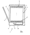
- the automatic dishwasher 1 has, as in Fig. 1 is shown by way of example, via a housing 2, which receives a rinsing container 3 providing a washing compartment 4.
- the rinse tank 3 is used in the intended use of receiving cleaning items to be cleaned, for which purpose typically Spülkörbe are provided, the sake of clarity in Fig. 1 are not shown.
- the washing compartment 4 provided by the washing container 3 is accessible via a feed opening 6. This is by means of a pivotally mounted on the housing 2 Spülraumt 6 fluid-tight closed.
- the dishwasher 1 further has a reservoir 7 for the Caching of rinsing liquor.
- This reservoir 7 may be formed within the housing 2 or outside thereof.
- the reservoir 7 is housed in the gap space not shown between the washing container 3 on the one hand and the housing 2 on the other hand, that is arranged laterally of the gap space at this.
- the reservoir 7 is fluidly coupled to the washing container 3. About this fluidic connection can be removed from the rinse tank 3 rinse and fed to the reservoir 5 or transferred in the reverse direction from the reservoir 7 in the washing compartment 3.
- the supply with rinsing carried out in the illustrated embodiment via a supply line 10, which is connected at one end to the reservoir 7 and the other end to a sump 9, wherein the sump 9 with respect to the drawing plane after Fig. 1 extends below the washing container 3.
- the rinsing fluid in the washing container 3 accumulates in the sump 9, from where it is pumped by means of a corresponding feed pump via the supply line 10 into the reservoir 7.
- the delivery rate of the feed pump determines the volume flow of rinsing liquor, which passes via the supply line 10 into the storage container 7 and, for example, amounts to 35 l / min.
- the feed pump may be the circulation pump, which has the main function to pressurize the sprayers with rinsing water in the circulation. But it may also be an additional pump, which (only) is used to promote the wash liquor in the reservoir.
- the reservoir 7 is inventively formed in the manner of a tube 8, which is laid meandering in the illustrated embodiment, as shown in the drawing Fig. 1 can be seen schematically. A detailed view of the reservoir 7 leaves Fig. 2 detect.
- the reservoir 7 is formed by a loop-shaped, that is meandering tube 8.
- the tube 8 consists of individual mutually parallel pipe sections 11, which are coupled to each other for a fluidic connection via end-mounted pipe bends 12.
- the tube 8 has an inner diameter which is between 5 mm and 11 mm, preferably between 6 mm and 10 mm, more preferably between 7 mm and 9 mm, most preferably 8 mm.
- Fig. 2 can recognize the pipe sections 11 may be formed differently long in the longitudinal direction, so that 7 recesses 17 may result in the final assembled state of the reservoir.
- the outside of the washing container 3 can otherwise project elements, projections or the like arranged on the outside.
- the inventive design of the reservoir 7 thus allows an optimized adaptation to the dishwasher provided by 1 available installation space.
- the reservoir 7 has on the input side via an inlet connection 13. About this passes in correspondence of the arrow 15 of the pump pumped rinsing water into the reservoir. 7
- an outlet connection 14 is provided, which is provided on the other side of the reservoir 7 forming tube 8. About this outlet pipe 14 can escape in the storage tank 7 cached rinsing and enter the washing compartment 3.
- the rinsing fluid cached in the storage container 7 germinates over time and deposits, germs and / or similar bio-films can also form inside the storage container 7, that is to say on its inner wall. This can cause unpleasant odors. There is also the risk that any deposits, germs and / or the like replace organic films, which can then lead to a functional impairment or even a complete failure of the reservoir 7 or even the entire dishwasher 1.
- the flow cross-section of the tube 8 is dimensioned such that sets in the intended use case with respect to the inflowing into the reservoir 7 rinsing at a predetermined volume flow, a minimum flow rate.
- the minimum flow rate is selected so that the required for a removal of a possibly located on the inner wall of the reservoir 7 Bio-film shear rate of, for example, 4 m / s is achieved.
Landscapes
- Washing And Drying Of Tableware (AREA)
Abstract
Description
- Die Erfindung betrifft einen Geschirrspülautomaten, insbesondere eine Haushaltsgeschirrspülmaschine, mit einem einen Spülraum bereitstellenden Spülbehälter, der der Aufnahme von zu reinigendem Spülgut dient, und mit einem Vorratsbehälter für die Zwischenspeicherung von Spülflotte, wobei der Vorratsbehälter an den Spülbehälter strömungstechnisch angeschlossen ist.
- Geschirrspülautomaten der gattungsgemäßen Art sind aus dem Stand der Technik an sich gut bekannt, weshalb es eines gesonderten druckschriftlichen Nachweises an dieser Stelle nicht bedarf.
- Geschirrspülautomaten der eingangs genannten Art verfügen über einen einen Spülraum bereitstellenden Spülbehälter, der im bestimmungsgemäßen Verwendungsfall der Aufnahme von zu reinigendem Spülgut dient. Zur Beschickung des Spülbehälters mit Spülgut dient eine Beschickungsöffnung, die mittels einer verschwenkbar gelagerten Spülraumtür fluiddicht verschließbar ist.
- Für eine Beaufschlagung von zu reinigendem Spülgut mit Spülflotte dienen innerhalb des Spülbehälters angeordnete Sprüheinrichtungen, vorzugsweise in der Ausgestaltung verdrehbar angeordneter Sprüharme. Diese werden im bestimmungsgemäßen Verwendungsfall mit Spülflotte versorgt, infolgedessen eine Beaufschlagung des zu reinigenden Spülgutes mit Spülflotte erfolgt.
- Gattungsgemäße Geschirrspülautomaten sind zum Zwecke der Wassereinsparung mit einem Vorratsbehälter zur Zwischenspeicherung von Spülflotte ausgerüstet. Ein solcher Vorratsbehälter dient dazu, am Ende eines bestimmungsgemäßen Programmablaufes im Spülbehälter noch befindliche Restspülflotte aufzunehmen und bis zum Beginn eines nächsten Spülprogramms zu bevorraten. Typischerweise wird die zum Ende eines Spülprogramms verhältnismäßig saubere Klarspülflotte zur Zwischenspeicherung genutzt. Mit Beginn eines neuen Spülprogramms wird die zwischengespeicherte Spülflotte in den Spülbehälter abgelassen, so dass nur noch eine um die Menge an zurückgeführter Spülflotte reduzierte Menge an Frischwasser für den Beginn eines neuen Spülprogramms erforderlich ist. In vorteilhafter Weise kann so eine Einsparung an Frischwasser erreicht werden.
- Die innerhalb des Vorratsbehälters zwischengespeicherte Spülflotte unterliegt der Verkeimung. Es kann infolgedessen auch zu Keimablagerungen, Verschmutzungen und/oder dergleichen Bio-Filme an der Innenwandung des Vorratsbehälters kommen. Dieser Bio-Film bleibt auch bei einem Abführen der zwischengespeicherten Spülflotte an der Innenwandung des Vorratsbehälters haften, so dass im Weiteren neu in den Vorratsbehälter eingeführte Spülflotte kontaminiert wird. Der aus der vorangegangenen Spülflottenbevorratung im Vorratsbehälter zurückgelassene Bio-Film wirkt für die neu in den Vorratsbehälter eingeführte Spülflotte als Keimbildner, so dass es zu einer sogenannten Wiederverkeimung kommt. Im Ergebnis einer solchen Kontamination kommt es zu einem vergleichsweise schnellen Keimwachstum innerhalb der neu in den Vorratsbehälter eingeführten Spülflotte.
- Das Problem der Wiederverkeimung ist im Stand der Technik nicht unbekannt. Es sind in diesem Zusammenhang zahlreiche Lösungen vorgeschlagen worden, die die Wiederverkeimung verhindern, zumindest aber verringern sollen. So ist zum Beispiel der Einsatz von UV-Lampen vorgeschlagen worden, die eine Abtötung sich im Vorratsbehälter unter Umständen ausbildender Keime bewirken sollen.
- Obgleich sich die aus dem Stand der Technik bekannten Maßnahmen zur Vermeidung, zumindest aber Reduzierung des sich im Vorratsbehälter über die Dauer niederschlagenden Bio-Films im alltäglichen Praxiseinsatz bewährt haben, besteht Bedarf an neuartigen Weiterentwicklungen, die insbesondere eine konstruktiv einfache Umsetzung gestatten.
- Es ist deshalb die Aufgabe der Erfindung, einen Geschirrspülautomaten vorzuschlagen, der bei einem gleichzeitig konstruktiv einfachen Aufbau die Entstehung eines Bio-Films im Vorratsbehälter vermeiden hilft.
- Zur Lösung dieser Aufgabe wird mit der Erfindung ein Geschirrspülautomat der eingangs genannten Art vorgeschlagen, der sich dadurch auszeichnet, dass der Vorratsbehälter nach Art eines Rohrs ausgebildet ist, dessen Durchströmungsquerschnitt derart bemessen ist, dass sich im bestimmungsgemäßen Verwendungsfall hinsichtlich der in den Vorratsbehälter einströmenden Spülflotte bei einem vorgegebenen Volumenstrom eine Mindest-Fließgeschwindigkeit einstellt.
- Es ist demnach erfindungsgemäß vorgesehen, den Vorratsbehälter im Unterschied zum Stand der Technik konstruktiv anders auszugestalten, und zwar nach Art eines Rohrs. Dabei ist das den Vorratsbehälter bildende Rohr hinsichtlich seines Durchströmungsquerschnitts derart bemessen, dass sich im bestimmungsgemäßen Verwendungsfall hinsichtlich der in den Vorratsbehälter einströmenden Spülflotte eine Mindest-Fließgeschwindigkeit einstellt. Diese Mindest-Fließgeschwindigkeit ergibt sich in Abhängigkeit des geförderten Volumenstroms an Spülflotte, was wiederum von der Drehzahl der eingesetzten Förderpumpe abhängt. Der Durchströmungsquerschnitt des Rohrs ist also an die Förderleistung der die Spülflotte fördernden Pumpe angepasst. Im Ergebnis ergibt sich eine Mindest-Fließgeschwindigkeit, mit der die Spülflotte in den als Rohr ausgebildeten Vorratsbehälter einströmt beziehungsweise diesen durchströmt.
- Die Mindest-Fließgeschwindigkeit der Spülflotte ist so ausgelegt, dass die sich an der Rohrinnenwandung des Vorratsbehälters einstellende Schergeschwindigkeit eine solche Scherkraft auf die Rohrinnenwandung ausübt, dass sich dort unter Umständen ausgebildete Ablagerungen, Verkeimungen und/oder dergleichen Bio-Filme mitgerissen werden. Es kommt insofern zu einer mechanischen Reinigung des Vorratsbehälters durch Abtrag infolge hoher Fließgeschwindigkeiten.
- Der erfindungsgemäße Grundgedanke besteht darin, dass der Vorratsbehälter in Abkehr zum Stand der Technik nicht als reiner Sammelbehälter für die Spülflotte ausgebildet ist. Er ist zum Zwecke der Erzielung hoher Fließgeschwindigkeiten vielmehr als Rohr bzw. rohrförmig ausgebildet. Die im Geschirrspülautomaten verbaute Förderpumpe vermag dabei einen vorgegebenen Volumenstrom zu fördern. In Abhängigkeit dieses vorgegebenen Volumenstroms, das heißt der Förderleistung der Förderpumpe ist das den Vorratsbehälter bildende Rohr hinsichtlich seines Durchströmungsquerschnitts auszulegen. Dabei ist der Durchströmungsquerschnitt derart zu wählen, dass die Spülflotte bei vorbekanntem Volumenstrom eine solche Fließgeschwindigkeit innerhalb des Rohres erreicht, dass die für einen Abtrag von an der Rohrinnenwand unter Umständen anhaftendem Bio-Film notwendige Schergeschwindigkeit erreicht wird. Es kommt insofern erfindungsgemäß nicht auf bestimmte Größen hinsichtlich des Durchströmungsquerschnitts, des Volumenstroms oder der Mindest-Fließgeschwindigkeit an. Entscheidend ist vielmehr die Abstimmung dieser Parameter im Verhältnis, so dass im Ergebnis die für ein Entfernen eines etwaigen Bio-Films erforderliche Schergeschwindigkeit erreicht wird.
- Die erfindungsgemäße Konstruktion erweist sich im Aufbau als sehr einfach. Es kommt als Vorratsbehälter ein Rohr oder ein rohrförmiger Körper zum Einsatz, dessen Erstreckung in Durchströmungsrichtung seinen Durchströmungsquerschnitt wesentlich übersteigt. Zusätzliche Einrichtungen zur Entkeimung und/oder Reinigung bedarf es nicht. Das den Vorratsbehälter ausbildende Rohr ist in seiner konstruktiven Ausgestaltung vielmehr so ausgelegt, dass im bestimmungsgemäßen Verwendungsfall eine Selbstreinigung stattfindet. Der in erfindungsgemäßer Weise ausgerüstete Geschirrspülautomat erlaubt mithin eine vergleichsweise einfache Handhabung, wobei insbesondere ein geringer Verschleiß und die aufgrund des einfachen Aufbaus bedingte Robustheit und geringe Störanfälligkeit von Vorteil sind.
- Der Durchströmungsquerschnitt des den Vorratsbehälter bildenden Rohrs beträgt zwischen 30 mm2 und 70 mm2, vorzugsweise zwischen 40 mm2 und 60 mm2, mehr bevorzugt zwischen 45 mm2 und 55 mm2, am meisten bevorzugt 50 mm2. Dabei gilt, dass der Durchströmungsquerschnitt in Abhängigkeit der Förderleistung der im Geschirrspülautomaten zum Einsatz kommenden Förderpumpe auszuwählen ist.
- Das den Vorratsbehälter bildende Rohr kann im Querschnitt bevorzugter Weise kreisförmig oder oval ausgebildet sein. Dabei hat die Ovalausgestaltung den Vorteil, da bei gleicher Rohrlänge ein größeres Volumen, das heißt Speichervolumen für die vom Vorratsbehälter aufzunehmende Spülflotte bereitsteht.
- Aus dem Stand der Technik vorbekannte Vorratsbehälter haben typischerweise ein Speichervolumen zwischen zwei Litern und vier Litern. Es wird mit der Erfindung deshalb vorgeschlagen, dass das den Vorratsbehälter bildende Rohr in Durchströmungsrichtung eine Länge zwischen 30 m und 100 m, vorzugsweise zwischen 40 m und 80 m, mehr bevorzugt zwischen 50 m und 60 m aufweist. Je nach gewähltem Durchströmungsquerschnitt kann so ein Speichervolumen zwischen zwei und vier Litern erreicht werden.
- Die Ausgestaltung des Vorratsbehälters als Rohr hat zudem den Vorteil, dass eine optimierte Raumnutzung innerhalb des Gehäuses des Geschirrspülautomaten stattfinden kann. So besteht insbesondere die Möglichkeit, den als Rohr ausgebildeten Vorratsbehälter in solchen Gehäusebereichen des Geschirrspülautomaten zu verlegen, die bislang als Toträume ungenutzt sind. In vorteilhafter Weise kann es so gestattet sein, den Spülbehälter im Unterschied zum Stand der Technik größer auszugestalten, das heißt das Beladevolumen zu vergrößern.
- Gemäß einer bevorzugten Ausführungsform der Erfindung ist vorgesehen, dass das Rohr mäanderförmig verlegt ist, das Rohr also in möglichst kompakter Form schlaufenweise ausgerichtet ist. Das Rohr kann in diesem Fall seitlich des Spülbehälters an diesem angeordnet sein.
- Weitere Merkmale und Vorteile der Erfindung ergeben sich aus der nachfolgenden Beschreibung anhand der Figuren. Dabei zeigen:
- Fig. 1
- in schematischer Darstellung einen Geschirrspülautomaten nach der Erfindung und
- Fig. 2
- in schematischer Darstellung einen nach der Erfindung ausgebildeten Vorratsbehälter zur Zwischenspeicherung von Spülflotte.
- Der Geschirrspülautomat 1 verfügt, wie in
Fig. 1 beispielhaft dargestellt ist, über ein Gehäuse 2, das einen einen Spülraum 4 bereitstellenden Spülbehälter 3 aufnimmt. Der Spülbehälter 3 dient im bestimmungsgemäßen Verwendungsfall der Aufnahme von zu reinigendem Spülgut, zu welchem Zweck typischerweise Spülkörbe vorgesehen sind, die der besseren Übersicht wegen inFig. 1 nicht dargestellt sind. - Der vom Spülbehälter 3 bereitgestellte Spülraum 4 ist über eine Beschickungsöffnung 6 zugänglich. Diese ist mittels einer verschwenkbar am Gehäuse 2 angeordneten Spülraumtür 6 fluiddicht verschließbar.
- Zur Beaufschlagung von zu reinigendem Spülgut mit Spülflotte sind innerhalb des Spülbehälters 3 in
Fig. 1 nicht näher dargestellte Sprüharme angeordnet. - Der Geschirrspülautomat 1 verfügt desweiteren über einen Vorratsbehälter 7 für die Zwischenspeicherung von Spülflotte. Dieser Vorratsbehälter 7 kann innerhalb des Gehäuses 2 oder auch außerhalb desselben ausgebildet sein. Im gezeigten Ausführungsbeispiel ist der Vorratsbehälter 7 im nicht näher dargestellten Spaltraum zwischen Spülbehälter 3 einerseits und Gehäuse 2 andererseits untergebracht, das heißt seitlich des Spaltraums an diesem angeordnet.
- Der Vorratsbehälter 7 ist strömungstechnisch mit dem Spülbehälter 3 gekoppelt. Über diese strömungstechnische Verbindung kann dem Spülbehälter 3 Spülflotte entnommen und dem Vorratsbehälter 5 zugeführt beziehungsweise in umgekehrter Richtung aus dem Vorratsbehälter 7 in den Spülbehälter 3 überführt werden. Die Zuführung mit Spülflotte erfolgt im dargestellten Ausführungsbeispiel über eine Zuführungsleitung 10, die einendseitig am Vorratsbehälter 7 und anderendseitig an einen Pumpentopf 9 angeschlossen ist, wobei sich der Pumpentopf 9 mit Bezug auf die Zeichnungsebene nach
Fig. 1 unterhalb des Spülbehälters 3 erstreckt. Im bestimmungsgemäßen Verwendungsfall sammelt sich die im Spülbehälter 3 befindliche Spülflotte im Pumpentopf 9 an, von wo aus sie mittels einer entsprechenden Förderpumpe über die Zuführungsleitung 10 in den Vorratsbehälter 7 gepumpt wird. Dabei bestimmt die Förderleistung der Förderpumpe den Volumenstrom an Spülflotte, der über die Zuführungsleitung 10 in den Vorratsbehälter 7 gelangt und der zum Beispiel 35 l/min beträgt. Bei der Förderpumpe kann es sich um die Umwälzpumpe handeln, welche die Hauptfunktion hat, im Umwälzbetrieb die Sprüheinrichtungen mit Spülflotte zu beaufschlagen. Es kann sich aber auch um eine zusätzliche Pumpe handeln, welche (lediglich) zur Förderung der Spülflotte in den Vorratsbehälter dient. - Der Vorratsbehälter 7 ist erfindungsgemäß nach Art eines Rohrs 8 ausgebildet, das im gezeigten Ausführungsbeispiel mäanderförmig verlegt ist, wie dies die Zeichnung nach
Fig. 1 schematisch erkennen lässt. Eine detaillierte Darstellung des Vorratsbehälters 7 lässtFig. 2 erkennen. - Wie sich aus der Darstellung nach
Fig. 2 ergibt, ist der Vorratsbehälter 7 durch ein schleifenförmig, das heißt mäanderförmig verlegtes Rohr 8 gebildet. Dabei besteht das Rohr 8 aus einzelnen parallel zueinander verlaufenden Rohrabschnitten 11, die für eine strömungstechnische Verbindung über endseitig angeordnete Rohrbögen 12 miteinander gekoppelt sind. Das Rohr 8 verfügt über einen Innendurchmesser, der zwischen 5 mm und 11 mm, vorzugsweise zwischen 6 mm und 10 mm, mehr bevorzugt zwischen 7 mm und 9 mm, am meisten bevorzugt 8 mm beträgt. - Wie die Darstellung nach
Fig. 2 erkennen lässt, können die Rohrabschnitte 11 in Längsrichtung unterschiedlich lang ausgebildet sein, so dass sich im endmontierten Zustand des Vorratsbehälters 7 Aussparungen 17 ergeben können. In derartige Aussparungen 17 können im endmontierten Zustand des Geschirrspülautomaten 1 anderweitig am Spülbehälter 3 außenseitig angeordnete Elemente, Vorsprünge oder dergleichen hineinragen. Die erfindungsgemäße Ausgestaltung des Vorratsbehälters 7 ermöglicht insofern eine optimierte Anpassung an den vom Geschirrspülautomaten 1 zur Verfügung gestellten Einbauraum. - Der Vorratsbehälter 7 verfügt eingangsseitig über einen Einlaufstutzen 13. Über diesen gelangt in Entsprechung des Pfeils 15 von der Förderpumpe geförderte Spülflotte in den Vorratsbehälter 7.
- Für eine Entleerung des Vorratsbehälters 7 ist ein Auslaufstutzen 14 vorgesehen, der anderendseitig des den Vorratsbehälter 7 bildenden Rohrs 8 vorgesehen ist. Über diesen Auslaufstutzen 14 kann im Vorratsbehälter 7 zwischengespeicherte Spülflotte abströmen und in den Spülbehälter 3 gelangen.
- Die im Vorratsbehälter 7 zwischengespeicherte Spülflotte verkeimt im Laufe der Zeit und es können sich Ablagerungen, Verkeimungen und/oder dergleichen Bio-Filme auch im Inneren des Vorratsbehälters 7, das heißt an dessen Innenwandung ausbilden. Hierdurch können unangenehme Gerüche entstehen. Es besteht zudem die Gefahr, dass sich etwaige Ablagerungen, Verkeimungen und/oder dergleichen Bio-Filme ablösen, was dann zu einer Funktionsbeeinträchtigung oder sogar zu einem Komplettausfall des Vorratsbehälters 7 oder sogar des gesamten Geschirrspülautomaten 1 führen kann. Um dieser Problematik vorzubeugen ist erfindungsgemäß vorgesehen, dass der Durchströmungsquerschnitt des Rohres 8 derart bemessen ist, dass sich im bestimmungsgemäßen Verwendungsfall hinsichtlich der in den Vorratsbehälter 7 einströmenden Spülflotte bei einem vorgegebenen Volumenstrom eine Mindest-Fließgeschwindigkeit einstellt. Dabei ist die Mindest-Fließgeschwindigkeit so gewählt, dass die für eine Entfernung eines sich unter Umständen an der Innenwandung des Vorratsbehälters 7 befindlichen Bio-Films erforderliche Schergeschwindigkeit von zum Beispiel 4 m/s erreicht wird.
- Infolgedessen kommt es zu einem Abtrag und anschließendem Austrag des Bio-Films aus dem Vorratsbehälter 7. Eine Kontamination, das heißt Wiederverkeimung einer im weiteren Programmablauf neu in den Vorratsbehälter eingeleiteten Spülflotte ist damit unterbunden. Und dies bei gleichzeitig einfachem Aufbau des Vorratsbehälters 7 und unter gleichzeitigem Verzicht auf separat zu handhabende und/oder zu bedienende Entkeimungseinrichtungen.
-
- 1
- Geschirrspülautomat
- 2
- Gehäuse
- 3
- Spülbehälter
- 4
- Spülraum
- 5
- Beschickungsöffnung
- 6
- Spülraumtür
- 7
- Vorratsbehälter
- 8
- Rohr
- 9
- Pumpentopf
- 10
- Zuführungsleitung
- 11
- Rohrabschnitt
- 12
- Rohrbogen
- 13
- Einlaufstutzen
- 14
- Auslaufstutzen
- 15
- Pfeil
- 16
- Pfeil
- 17
- Aussparung
Claims (7)
- Geschirrspülautomat, insbesondere Haushaltsgeschirrspülmaschine, mit einem einen Spülraum (4) bereitstellenden Spülbehälter (3), der der Aufnahme von zu reinigendem Spülgut dient, und mit einem Vorratsbehälter (7) für die Zwischenspeicherung von Spülflotte, wobei der Vorratsbehälter (7) an den Spülbehälter strömungstechnisch angeschlossen ist,
dadurch gekennzeichnet,
dass der Vorratsbehälter (7) nach Art eines Rohrs (8) ausgebildet ist, dessen Durchströmungsquerschnitt derart bemessen ist, dass sich im bestimmungsgemäßen Verwendungsfall hinsichtlich der in den Vorratsbehälter (7) einströmenden Spülflotte bei einem vorgegebenen Volumenstrom eine Mindest-Fließgeschwindigkeit einstellt. - Geschirrspülautomat nach Anspruch 1,
dadurch gekennzeichnet,
dass der Durchströmungsquerschnitt 30 mm2 bis 70 mm2, vorzugsweise 40 mm2 bis 60 mm2, mehr bevorzugt 45 mm2 bis 55 mm2, am meisten bevorzugt 50 mm2 beträgt. - Geschirrspülautomat nach Anspruch 1 oder 2,
dadurch gekennzeichnet,
dass das Rohr (8) im Querschnitt kreisförmig ausgebildet ist. - Geschirrspülautomat nach Anspruch 1 oder 2,
dadurch gekennzeichnet,
dass das Rohr (8) im Querschnitt oval ausgebildet ist. - Geschirrspülautomat nach einem der vorhergehenden Ansprüche,
dadurch gekennzeichnet,
dass das Rohr (8) in Durchströmungsrichtung eine Länge von 30 m bis 100 m, vorzugsweise von 40 m bis 80 m, mehr bevorzugt von 50 m bis 60 m aufweist. - Geschirrspülautomat nach einem der vorhergehenden Ansprüche,
dadurch gekennzeichnet,
dass das Rohr (8) mäanderförmig verlegt ist. - Geschirrspülautomat nach einem der vorhergehenden Ansprüche,
dadurch gekennzeichnet,
dass das Rohr (8) seitlich des Spülbehälters (3) an diesem angeordnet ist.
Applications Claiming Priority (1)
| Application Number | Priority Date | Filing Date | Title |
|---|---|---|---|
| DE201210109363 DE102012109363A1 (de) | 2012-10-02 | 2012-10-02 | Geschirrspülautomat, insbesondere Haushaltsgeschirrspülmaschine |
Publications (2)
| Publication Number | Publication Date |
|---|---|
| EP2716199A1 true EP2716199A1 (de) | 2014-04-09 |
| EP2716199B1 EP2716199B1 (de) | 2017-01-18 |
Family
ID=49485685
Family Applications (1)
| Application Number | Title | Priority Date | Filing Date |
|---|---|---|---|
| EP13401107.1A Active EP2716199B1 (de) | 2012-10-02 | 2013-10-01 | Geschirrspülautomat, insbesondere Haushaltsgeschirrspülmaschine |
Country Status (2)
| Country | Link |
|---|---|
| EP (1) | EP2716199B1 (de) |
| DE (1) | DE102012109363A1 (de) |
Citations (3)
| Publication number | Priority date | Publication date | Assignee | Title |
|---|---|---|---|---|
| EP2064982A1 (de) * | 2009-02-09 | 2009-06-03 | V-Zug AG | Geschirrspüler mit Wärmepumpe |
| DE102009029115A1 (de) * | 2009-09-02 | 2011-03-03 | BSH Bosch und Siemens Hausgeräte GmbH | Geschirrspülmaschine sowie Verfahren zum Betrieb einer Geschirrspülmaschine |
| WO2013171090A1 (de) * | 2012-05-14 | 2013-11-21 | BSH Bosch und Siemens Hausgeräte GmbH | Vorrichtung zum zwischenspeichern von betriebsflüssigkeit |
-
2012
- 2012-10-02 DE DE201210109363 patent/DE102012109363A1/de not_active Withdrawn
-
2013
- 2013-10-01 EP EP13401107.1A patent/EP2716199B1/de active Active
Patent Citations (3)
| Publication number | Priority date | Publication date | Assignee | Title |
|---|---|---|---|---|
| EP2064982A1 (de) * | 2009-02-09 | 2009-06-03 | V-Zug AG | Geschirrspüler mit Wärmepumpe |
| DE102009029115A1 (de) * | 2009-09-02 | 2011-03-03 | BSH Bosch und Siemens Hausgeräte GmbH | Geschirrspülmaschine sowie Verfahren zum Betrieb einer Geschirrspülmaschine |
| WO2013171090A1 (de) * | 2012-05-14 | 2013-11-21 | BSH Bosch und Siemens Hausgeräte GmbH | Vorrichtung zum zwischenspeichern von betriebsflüssigkeit |
Also Published As
| Publication number | Publication date |
|---|---|
| EP2716199B1 (de) | 2017-01-18 |
| DE102012109363A1 (de) | 2014-04-03 |
Similar Documents
| Publication | Publication Date | Title |
|---|---|---|
| EP1460927B1 (de) | Geschirrspülmaschine zur aufnahme von in einem spülbehälter angeordnetem reinigungsgut | |
| DE102012017377B4 (de) | Waschgerät zum Reinigen von Teilen wie Maschinenteilen oder dergleichen | |
| EP2462272B1 (de) | Wasserführendes hausgerät mit einer filtereinrichtung im abpumpstrang und speicher | |
| EP3451892B1 (de) | Flaschenspülkorbvorrichtung sowie geschirrspülmaschine mit einer solchen vorrichtung | |
| DE102019121736B4 (de) | Geschirrspülmaschine und Verfahren zum Betrieb einer Geschirrspülmaschine | |
| EP3777637B1 (de) | Geschirrspülmaschine, insbesondere haushaltsgeschirrspülmaschine | |
| EP3285632A1 (de) | Sprüharm und geschirrspülmaschine | |
| EP2072000A1 (de) | Geschirrspülmaschine in Form eines Programmautomaten und Verfahren zu deren Betrieb | |
| EP2759244B1 (de) | Geschirrspülautomat sowie Verfahren zur Einleitung von Frischwasser in einen Geschirrspülautomaten | |
| EP2850240B1 (de) | Vorrichtung zum zwischenspeichern von betriebsflüssigkeit | |
| DE102011017294A1 (de) | Transportspülmaschine mit Sonderbehandlungszonen | |
| EP2716199B1 (de) | Geschirrspülautomat, insbesondere Haushaltsgeschirrspülmaschine | |
| EP2656768A1 (de) | Reinigungs- und Desinfektionsautomat | |
| DE102017129052B4 (de) | Geschirrspülmaschine | |
| DE102006025508A1 (de) | Reinigungssystem zum Reinigen eines Back- oder Kombidämpfer-Geräts | |
| EP1830688A1 (de) | Wasserf]hrendes haushaltsger[t und verfahren zum betreiben desselben | |
| DE102011007685A1 (de) | Geschirrspülmaschine | |
| DE102008045783B4 (de) | Düsenvorrichtung eines Geschirrspülers | |
| CH421412A (de) | Reinigungsautomat zum Waschen und Spülen von Geschirr, Kannen, Gläsern od. dgl. Artikel | |
| EP3473156B1 (de) | Geschirrspülmaschine | |
| DE102015224667B3 (de) | Wäschepflegegerät mit einer Belüftungsleitung | |
| DE102009042866B4 (de) | Geschirrspülmaschine und Verfahren zum Spülen von Geschirr | |
| EP2491843B1 (de) | Verfahren zur Durchführung eines Spülprogramms, welches mindestens die Programmabschnitte Reinigen, Zwischenspülen und Klarspülen umfasst | |
| EP3868277B1 (de) | Wascharm | |
| DE10210983B4 (de) | Industrielle Reinigungsanlage mit einer Selektionsvorrichtung für gebrauchte Reinigungsflüssigkeiten |
Legal Events
| Date | Code | Title | Description |
|---|---|---|---|
| PUAI | Public reference made under article 153(3) epc to a published international application that has entered the european phase |
Free format text: ORIGINAL CODE: 0009012 |
|
| AK | Designated contracting states |
Kind code of ref document: A1 Designated state(s): AL AT BE BG CH CY CZ DE DK EE ES FI FR GB GR HR HU IE IS IT LI LT LU LV MC MK MT NL NO PL PT RO RS SE SI SK SM TR |
|
| AX | Request for extension of the european patent |
Extension state: BA ME |
|
| 17P | Request for examination filed |
Effective date: 20141009 |
|
| RBV | Designated contracting states (corrected) |
Designated state(s): AL AT BE BG CH CY CZ DE DK EE ES FI FR GB GR HR HU IE IS IT LI LT LU LV MC MK MT NL NO PL PT RO RS SE SI SK SM TR |
|
| GRAP | Despatch of communication of intention to grant a patent |
Free format text: ORIGINAL CODE: EPIDOSNIGR1 |
|
| RIC1 | Information provided on ipc code assigned before grant |
Ipc: A47L 15/42 20060101ALI20151112BHEP Ipc: A47L 15/00 20060101AFI20151112BHEP |
|
| INTG | Intention to grant announced |
Effective date: 20151130 |
|
| 17Q | First examination report despatched |
Effective date: 20160128 |
|
| INTC | Intention to grant announced (deleted) | ||
| GRAP | Despatch of communication of intention to grant a patent |
Free format text: ORIGINAL CODE: EPIDOSNIGR1 |
|
| INTG | Intention to grant announced |
Effective date: 20160912 |
|
| GRAS | Grant fee paid |
Free format text: ORIGINAL CODE: EPIDOSNIGR3 |
|
| GRAA | (expected) grant |
Free format text: ORIGINAL CODE: 0009210 |
|
| AK | Designated contracting states |
Kind code of ref document: B1 Designated state(s): AL AT BE BG CH CY CZ DE DK EE ES FI FR GB GR HR HU IE IS IT LI LT LU LV MC MK MT NL NO PL PT RO RS SE SI SK SM TR |
|
| REG | Reference to a national code |
Ref country code: GB Ref legal event code: FG4D Free format text: NOT ENGLISH |
|
| REG | Reference to a national code |
Ref country code: CH Ref legal event code: EP |
|
| REG | Reference to a national code |
Ref country code: DE Ref legal event code: R084 Ref document number: 502013006142 Country of ref document: DE |
|
| REG | Reference to a national code |
Ref country code: AT Ref legal event code: REF Ref document number: 862394 Country of ref document: AT Kind code of ref document: T Effective date: 20170215 |
|
| REG | Reference to a national code |
Ref country code: IE Ref legal event code: FG4D Free format text: LANGUAGE OF EP DOCUMENT: GERMAN |
|
| REG | Reference to a national code |
Ref country code: DE Ref legal event code: R096 Ref document number: 502013006142 Country of ref document: DE |
|
| REG | Reference to a national code |
Ref country code: NL Ref legal event code: MP Effective date: 20170118 |
|
| REG | Reference to a national code |
Ref country code: LT Ref legal event code: MG4D |
|
| PG25 | Lapsed in a contracting state [announced via postgrant information from national office to epo] |
Ref country code: NL Free format text: LAPSE BECAUSE OF FAILURE TO SUBMIT A TRANSLATION OF THE DESCRIPTION OR TO PAY THE FEE WITHIN THE PRESCRIBED TIME-LIMIT Effective date: 20170118 |
|
| PG25 | Lapsed in a contracting state [announced via postgrant information from national office to epo] |
Ref country code: FI Free format text: LAPSE BECAUSE OF FAILURE TO SUBMIT A TRANSLATION OF THE DESCRIPTION OR TO PAY THE FEE WITHIN THE PRESCRIBED TIME-LIMIT Effective date: 20170118 Ref country code: GR Free format text: LAPSE BECAUSE OF FAILURE TO SUBMIT A TRANSLATION OF THE DESCRIPTION OR TO PAY THE FEE WITHIN THE PRESCRIBED TIME-LIMIT Effective date: 20170419 Ref country code: HR Free format text: LAPSE BECAUSE OF FAILURE TO SUBMIT A TRANSLATION OF THE DESCRIPTION OR TO PAY THE FEE WITHIN THE PRESCRIBED TIME-LIMIT Effective date: 20170118 Ref country code: NO Free format text: LAPSE BECAUSE OF FAILURE TO SUBMIT A TRANSLATION OF THE DESCRIPTION OR TO PAY THE FEE WITHIN THE PRESCRIBED TIME-LIMIT Effective date: 20170418 Ref country code: IS Free format text: LAPSE BECAUSE OF FAILURE TO SUBMIT A TRANSLATION OF THE DESCRIPTION OR TO PAY THE FEE WITHIN THE PRESCRIBED TIME-LIMIT Effective date: 20170518 Ref country code: LT Free format text: LAPSE BECAUSE OF FAILURE TO SUBMIT A TRANSLATION OF THE DESCRIPTION OR TO PAY THE FEE WITHIN THE PRESCRIBED TIME-LIMIT Effective date: 20170118 |
|
| PG25 | Lapsed in a contracting state [announced via postgrant information from national office to epo] |
Ref country code: PL Free format text: LAPSE BECAUSE OF FAILURE TO SUBMIT A TRANSLATION OF THE DESCRIPTION OR TO PAY THE FEE WITHIN THE PRESCRIBED TIME-LIMIT Effective date: 20170118 Ref country code: ES Free format text: LAPSE BECAUSE OF FAILURE TO SUBMIT A TRANSLATION OF THE DESCRIPTION OR TO PAY THE FEE WITHIN THE PRESCRIBED TIME-LIMIT Effective date: 20170118 Ref country code: LV Free format text: LAPSE BECAUSE OF FAILURE TO SUBMIT A TRANSLATION OF THE DESCRIPTION OR TO PAY THE FEE WITHIN THE PRESCRIBED TIME-LIMIT Effective date: 20170118 Ref country code: BG Free format text: LAPSE BECAUSE OF FAILURE TO SUBMIT A TRANSLATION OF THE DESCRIPTION OR TO PAY THE FEE WITHIN THE PRESCRIBED TIME-LIMIT Effective date: 20170418 Ref country code: RS Free format text: LAPSE BECAUSE OF FAILURE TO SUBMIT A TRANSLATION OF THE DESCRIPTION OR TO PAY THE FEE WITHIN THE PRESCRIBED TIME-LIMIT Effective date: 20170118 Ref country code: SE Free format text: LAPSE BECAUSE OF FAILURE TO SUBMIT A TRANSLATION OF THE DESCRIPTION OR TO PAY THE FEE WITHIN THE PRESCRIBED TIME-LIMIT Effective date: 20170118 Ref country code: PT Free format text: LAPSE BECAUSE OF FAILURE TO SUBMIT A TRANSLATION OF THE DESCRIPTION OR TO PAY THE FEE WITHIN THE PRESCRIBED TIME-LIMIT Effective date: 20170518 |
|
| REG | Reference to a national code |
Ref country code: DE Ref legal event code: R097 Ref document number: 502013006142 Country of ref document: DE |
|
| PG25 | Lapsed in a contracting state [announced via postgrant information from national office to epo] |
Ref country code: SK Free format text: LAPSE BECAUSE OF FAILURE TO SUBMIT A TRANSLATION OF THE DESCRIPTION OR TO PAY THE FEE WITHIN THE PRESCRIBED TIME-LIMIT Effective date: 20170118 Ref country code: RO Free format text: LAPSE BECAUSE OF FAILURE TO SUBMIT A TRANSLATION OF THE DESCRIPTION OR TO PAY THE FEE WITHIN THE PRESCRIBED TIME-LIMIT Effective date: 20170118 Ref country code: CZ Free format text: LAPSE BECAUSE OF FAILURE TO SUBMIT A TRANSLATION OF THE DESCRIPTION OR TO PAY THE FEE WITHIN THE PRESCRIBED TIME-LIMIT Effective date: 20170118 Ref country code: EE Free format text: LAPSE BECAUSE OF FAILURE TO SUBMIT A TRANSLATION OF THE DESCRIPTION OR TO PAY THE FEE WITHIN THE PRESCRIBED TIME-LIMIT Effective date: 20170118 |
|
| REG | Reference to a national code |
Ref country code: FR Ref legal event code: PLFP Year of fee payment: 5 |
|
| PLBE | No opposition filed within time limit |
Free format text: ORIGINAL CODE: 0009261 |
|
| STAA | Information on the status of an ep patent application or granted ep patent |
Free format text: STATUS: NO OPPOSITION FILED WITHIN TIME LIMIT |
|
| PG25 | Lapsed in a contracting state [announced via postgrant information from national office to epo] |
Ref country code: SM Free format text: LAPSE BECAUSE OF FAILURE TO SUBMIT A TRANSLATION OF THE DESCRIPTION OR TO PAY THE FEE WITHIN THE PRESCRIBED TIME-LIMIT Effective date: 20170118 Ref country code: DK Free format text: LAPSE BECAUSE OF FAILURE TO SUBMIT A TRANSLATION OF THE DESCRIPTION OR TO PAY THE FEE WITHIN THE PRESCRIBED TIME-LIMIT Effective date: 20170118 |
|
| 26N | No opposition filed |
Effective date: 20171019 |
|
| PG25 | Lapsed in a contracting state [announced via postgrant information from national office to epo] |
Ref country code: SI Free format text: LAPSE BECAUSE OF FAILURE TO SUBMIT A TRANSLATION OF THE DESCRIPTION OR TO PAY THE FEE WITHIN THE PRESCRIBED TIME-LIMIT Effective date: 20170118 |
|
| PG25 | Lapsed in a contracting state [announced via postgrant information from national office to epo] |
Ref country code: MC Free format text: LAPSE BECAUSE OF FAILURE TO SUBMIT A TRANSLATION OF THE DESCRIPTION OR TO PAY THE FEE WITHIN THE PRESCRIBED TIME-LIMIT Effective date: 20170118 |
|
| REG | Reference to a national code |
Ref country code: CH Ref legal event code: PL |
|
| REG | Reference to a national code |
Ref country code: IE Ref legal event code: MM4A |
|
| PG25 | Lapsed in a contracting state [announced via postgrant information from national office to epo] |
Ref country code: LU Free format text: LAPSE BECAUSE OF NON-PAYMENT OF DUE FEES Effective date: 20171001 Ref country code: CH Free format text: LAPSE BECAUSE OF NON-PAYMENT OF DUE FEES Effective date: 20171031 Ref country code: LI Free format text: LAPSE BECAUSE OF NON-PAYMENT OF DUE FEES Effective date: 20171031 |
|
| REG | Reference to a national code |
Ref country code: BE Ref legal event code: MM Effective date: 20171031 |
|
| PG25 | Lapsed in a contracting state [announced via postgrant information from national office to epo] |
Ref country code: BE Free format text: LAPSE BECAUSE OF NON-PAYMENT OF DUE FEES Effective date: 20171031 |
|
| PG25 | Lapsed in a contracting state [announced via postgrant information from national office to epo] |
Ref country code: MT Free format text: LAPSE BECAUSE OF FAILURE TO SUBMIT A TRANSLATION OF THE DESCRIPTION OR TO PAY THE FEE WITHIN THE PRESCRIBED TIME-LIMIT Effective date: 20170118 |
|
| REG | Reference to a national code |
Ref country code: FR Ref legal event code: PLFP Year of fee payment: 6 |
|
| PG25 | Lapsed in a contracting state [announced via postgrant information from national office to epo] |
Ref country code: IE Free format text: LAPSE BECAUSE OF NON-PAYMENT OF DUE FEES Effective date: 20171001 |
|
| PG25 | Lapsed in a contracting state [announced via postgrant information from national office to epo] |
Ref country code: HU Free format text: LAPSE BECAUSE OF FAILURE TO SUBMIT A TRANSLATION OF THE DESCRIPTION OR TO PAY THE FEE WITHIN THE PRESCRIBED TIME-LIMIT; INVALID AB INITIO Effective date: 20131001 |
|
| PG25 | Lapsed in a contracting state [announced via postgrant information from national office to epo] |
Ref country code: CY Free format text: LAPSE BECAUSE OF NON-PAYMENT OF DUE FEES Effective date: 20170118 |
|
| PG25 | Lapsed in a contracting state [announced via postgrant information from national office to epo] |
Ref country code: MK Free format text: LAPSE BECAUSE OF FAILURE TO SUBMIT A TRANSLATION OF THE DESCRIPTION OR TO PAY THE FEE WITHIN THE PRESCRIBED TIME-LIMIT Effective date: 20170118 |
|
| REG | Reference to a national code |
Ref country code: AT Ref legal event code: MM01 Ref document number: 862394 Country of ref document: AT Kind code of ref document: T Effective date: 20181001 |
|
| PG25 | Lapsed in a contracting state [announced via postgrant information from national office to epo] |
Ref country code: AT Free format text: LAPSE BECAUSE OF NON-PAYMENT OF DUE FEES Effective date: 20181001 |
|
| PG25 | Lapsed in a contracting state [announced via postgrant information from national office to epo] |
Ref country code: AL Free format text: LAPSE BECAUSE OF FAILURE TO SUBMIT A TRANSLATION OF THE DESCRIPTION OR TO PAY THE FEE WITHIN THE PRESCRIBED TIME-LIMIT Effective date: 20170118 |
|
| PGFP | Annual fee paid to national office [announced via postgrant information from national office to epo] |
Ref country code: TR Payment date: 20220920 Year of fee payment: 10 |
|
| PGFP | Annual fee paid to national office [announced via postgrant information from national office to epo] |
Ref country code: IT Payment date: 20221020 Year of fee payment: 10 |
|
| P01 | Opt-out of the competence of the unified patent court (upc) registered |
Effective date: 20230529 |
|
| PG25 | Lapsed in a contracting state [announced via postgrant information from national office to epo] |
Ref country code: IT Free format text: LAPSE BECAUSE OF NON-PAYMENT OF DUE FEES Effective date: 20231001 |
|
| PG25 | Lapsed in a contracting state [announced via postgrant information from national office to epo] |
Ref country code: IT Free format text: LAPSE BECAUSE OF NON-PAYMENT OF DUE FEES Effective date: 20231001 |
|
| PGFP | Annual fee paid to national office [announced via postgrant information from national office to epo] |
Ref country code: GB Payment date: 20241022 Year of fee payment: 12 |
|
| PGFP | Annual fee paid to national office [announced via postgrant information from national office to epo] |
Ref country code: FR Payment date: 20241025 Year of fee payment: 12 |
|
| PGFP | Annual fee paid to national office [announced via postgrant information from national office to epo] |
Ref country code: DE Payment date: 20251031 Year of fee payment: 13 |
|
| GBPC | Gb: european patent ceased through non-payment of renewal fee |
Effective date: 20251001 |
|
| PG25 | Lapsed in a contracting state [announced via postgrant information from national office to epo] |
Ref country code: TR Free format text: LAPSE BECAUSE OF NON-PAYMENT OF DUE FEES Effective date: 20231001 |
|
| PG25 | Lapsed in a contracting state [announced via postgrant information from national office to epo] |
Ref country code: GB Free format text: LAPSE BECAUSE OF NON-PAYMENT OF DUE FEES Effective date: 20251001 |
|
| PG25 | Lapsed in a contracting state [announced via postgrant information from national office to epo] |
Ref country code: FR Free format text: LAPSE BECAUSE OF NON-PAYMENT OF DUE FEES Effective date: 20251031 |