EP2715548B1 - Dynamic memory cache size adjustment in a memory device - Google Patents
Dynamic memory cache size adjustment in a memory device Download PDFInfo
- Publication number
- EP2715548B1 EP2715548B1 EP12794100.3A EP12794100A EP2715548B1 EP 2715548 B1 EP2715548 B1 EP 2715548B1 EP 12794100 A EP12794100 A EP 12794100A EP 2715548 B1 EP2715548 B1 EP 2715548B1
- Authority
- EP
- European Patent Office
- Prior art keywords
- memory
- cache
- size
- available
- array
- Prior art date
- Legal status (The legal status is an assumption and is not a legal conclusion. Google has not performed a legal analysis and makes no representation as to the accuracy of the status listed.)
- Active
Links
Images


Classifications
-
- G—PHYSICS
- G06—COMPUTING; CALCULATING OR COUNTING
- G06F—ELECTRIC DIGITAL DATA PROCESSING
- G06F12/00—Accessing, addressing or allocating within memory systems or architectures
- G06F12/02—Addressing or allocation; Relocation
- G06F12/08—Addressing or allocation; Relocation in hierarchically structured memory systems, e.g. virtual memory systems
- G06F12/0802—Addressing of a memory level in which the access to the desired data or data block requires associative addressing means, e.g. caches
- G06F12/0866—Addressing of a memory level in which the access to the desired data or data block requires associative addressing means, e.g. caches for peripheral storage systems, e.g. disk cache
- G06F12/0871—Allocation or management of cache space
-
- G—PHYSICS
- G06—COMPUTING; CALCULATING OR COUNTING
- G06F—ELECTRIC DIGITAL DATA PROCESSING
- G06F12/00—Accessing, addressing or allocating within memory systems or architectures
- G06F12/02—Addressing or allocation; Relocation
- G06F12/0223—User address space allocation, e.g. contiguous or non contiguous base addressing
- G06F12/023—Free address space management
- G06F12/0238—Memory management in non-volatile memory, e.g. resistive RAM or ferroelectric memory
- G06F12/0246—Memory management in non-volatile memory, e.g. resistive RAM or ferroelectric memory in block erasable memory, e.g. flash memory
-
- G—PHYSICS
- G06—COMPUTING; CALCULATING OR COUNTING
- G06F—ELECTRIC DIGITAL DATA PROCESSING
- G06F12/00—Accessing, addressing or allocating within memory systems or architectures
- G06F12/02—Addressing or allocation; Relocation
- G06F12/08—Addressing or allocation; Relocation in hierarchically structured memory systems, e.g. virtual memory systems
- G06F12/0802—Addressing of a memory level in which the access to the desired data or data block requires associative addressing means, e.g. caches
- G06F12/0806—Multiuser, multiprocessor or multiprocessing cache systems
- G06F12/0815—Cache consistency protocols
-
- G—PHYSICS
- G06—COMPUTING; CALCULATING OR COUNTING
- G06F—ELECTRIC DIGITAL DATA PROCESSING
- G06F12/00—Accessing, addressing or allocating within memory systems or architectures
- G06F12/02—Addressing or allocation; Relocation
- G06F12/08—Addressing or allocation; Relocation in hierarchically structured memory systems, e.g. virtual memory systems
- G06F12/0802—Addressing of a memory level in which the access to the desired data or data block requires associative addressing means, e.g. caches
- G06F12/0893—Caches characterised by their organisation or structure
-
- G—PHYSICS
- G11—INFORMATION STORAGE
- G11C—STATIC STORES
- G11C16/00—Erasable programmable read-only memories
- G11C16/02—Erasable programmable read-only memories electrically programmable
- G11C16/04—Erasable programmable read-only memories electrically programmable using variable threshold transistors, e.g. FAMOS
- G11C16/0483—Erasable programmable read-only memories electrically programmable using variable threshold transistors, e.g. FAMOS comprising cells having several storage transistors connected in series
-
- G—PHYSICS
- G06—COMPUTING; CALCULATING OR COUNTING
- G06F—ELECTRIC DIGITAL DATA PROCESSING
- G06F2212/00—Indexing scheme relating to accessing, addressing or allocation within memory systems or architectures
- G06F2212/10—Providing a specific technical effect
- G06F2212/1016—Performance improvement
-
- G—PHYSICS
- G06—COMPUTING; CALCULATING OR COUNTING
- G06F—ELECTRIC DIGITAL DATA PROCESSING
- G06F2212/00—Indexing scheme relating to accessing, addressing or allocation within memory systems or architectures
- G06F2212/10—Providing a specific technical effect
- G06F2212/1032—Reliability improvement, data loss prevention, degraded operation etc
-
- G—PHYSICS
- G06—COMPUTING; CALCULATING OR COUNTING
- G06F—ELECTRIC DIGITAL DATA PROCESSING
- G06F2212/00—Indexing scheme relating to accessing, addressing or allocation within memory systems or architectures
- G06F2212/10—Providing a specific technical effect
- G06F2212/1041—Resource optimization
- G06F2212/1044—Space efficiency improvement
-
- G—PHYSICS
- G06—COMPUTING; CALCULATING OR COUNTING
- G06F—ELECTRIC DIGITAL DATA PROCESSING
- G06F2212/00—Indexing scheme relating to accessing, addressing or allocation within memory systems or architectures
- G06F2212/22—Employing cache memory using specific memory technology
- G06F2212/222—Non-volatile memory
-
- G—PHYSICS
- G06—COMPUTING; CALCULATING OR COUNTING
- G06F—ELECTRIC DIGITAL DATA PROCESSING
- G06F2212/00—Indexing scheme relating to accessing, addressing or allocation within memory systems or architectures
- G06F2212/22—Employing cache memory using specific memory technology
- G06F2212/224—Disk storage
-
- G—PHYSICS
- G06—COMPUTING; CALCULATING OR COUNTING
- G06F—ELECTRIC DIGITAL DATA PROCESSING
- G06F2212/00—Indexing scheme relating to accessing, addressing or allocation within memory systems or architectures
- G06F2212/60—Details of cache memory
- G06F2212/601—Reconfiguration of cache memory
-
- G—PHYSICS
- G06—COMPUTING; CALCULATING OR COUNTING
- G06F—ELECTRIC DIGITAL DATA PROCESSING
- G06F2212/00—Indexing scheme relating to accessing, addressing or allocation within memory systems or architectures
- G06F2212/60—Details of cache memory
- G06F2212/6042—Allocation of cache space to multiple users or processors
- G06F2212/6046—Using a specific cache allocation policy other than replacement policy
-
- G—PHYSICS
- G06—COMPUTING; CALCULATING OR COUNTING
- G06F—ELECTRIC DIGITAL DATA PROCESSING
- G06F2212/00—Indexing scheme relating to accessing, addressing or allocation within memory systems or architectures
- G06F2212/62—Details of cache specific to multiprocessor cache arrangements
- G06F2212/621—Coherency control relating to peripheral accessing, e.g. from DMA or I/O device
-
- G—PHYSICS
- G06—COMPUTING; CALCULATING OR COUNTING
- G06F—ELECTRIC DIGITAL DATA PROCESSING
- G06F2212/00—Indexing scheme relating to accessing, addressing or allocation within memory systems or architectures
- G06F2212/72—Details relating to flash memory management
- G06F2212/7203—Temporary buffering, e.g. using volatile buffer or dedicated buffer blocks
-
- G—PHYSICS
- G06—COMPUTING; CALCULATING OR COUNTING
- G06F—ELECTRIC DIGITAL DATA PROCESSING
- G06F2212/00—Indexing scheme relating to accessing, addressing or allocation within memory systems or architectures
- G06F2212/72—Details relating to flash memory management
- G06F2212/7206—Reconfiguration of flash memory system
-
- G—PHYSICS
- G11—INFORMATION STORAGE
- G11C—STATIC STORES
- G11C11/00—Digital stores characterised by the use of particular electric or magnetic storage elements; Storage elements therefor
- G11C11/56—Digital stores characterised by the use of particular electric or magnetic storage elements; Storage elements therefor using storage elements with more than two stable states represented by steps, e.g. of voltage, current, phase, frequency
- G11C11/5621—Digital stores characterised by the use of particular electric or magnetic storage elements; Storage elements therefor using storage elements with more than two stable states represented by steps, e.g. of voltage, current, phase, frequency using charge storage in a floating gate
- G11C11/5628—Programming or writing circuits; Data input circuits
-
- G—PHYSICS
- G11—INFORMATION STORAGE
- G11C—STATIC STORES
- G11C16/00—Erasable programmable read-only memories
- G11C16/02—Erasable programmable read-only memories electrically programmable
- G11C16/06—Auxiliary circuits, e.g. for writing into memory
Definitions
- the present embodiments relate generally to memory and a particular embodiment relates to dynamic SLC cache in an MLC memory.
- Flash memory devices have developed into a popular source of non-volatile memory for a wide range of electronic applications. Flash memory devices typically use a one-transistor memory cell that allows for high memory densities, high reliability, and low power consumption. Common uses for flash memory include personal computers, flash drives, digital cameras, and cellular telephones. Program code and system data such as a basic input/output system (BIOS) are typically stored in flash memory devices for use in personal computer systems.
- BIOS basic input/output system
- a typical flash memory device is a type of memory in which the array of memory cells is typically organized into memory blocks that can be erased on a block-by-block basis (and reprogrammed on a page-by-page basis). Changes in a threshold voltage of each of the memory cells, through erasing or programming of a charge storage structure (e.g., floating gate or charge trap) or other physical phenomena (e.g., phase change or polarization), determine the data value programmed into each cell. The data in a cell of this type is determined by the presence or absence of the charge in the charge storage structure.
- a charge storage structure e.g., floating gate or charge trap
- phase change or polarization e.g., phase change or polarization
- a programming operation typically comprises a series of incrementally increasing programming pulses that are applied to a control gate of a memory cell being programmed in order to increase that particular memory cell's threshold voltage.
- Each memory cell can be programmed as single level cell (SLC) memory or multiple level cell (MLC) memory where the cell's threshold voltage (V t ) is indicative of the data value programmed into that cell.
- V t threshold voltage
- a V t of 2.5V might indicate a programmed cell while a V t of-0.5V might indicate an erased cell.
- An MLC memory uses multiple V t ranges that each indicates a different state.
- Multilevel cells can take advantage of the analog nature of a traditional flash cell by assigning a bit pattern to a specific V t range. This technology permits the storage of data values representing two or more bits per cell, depending on the quantity of V t ranges assigned to the cell.
- a fixed cache of memory cells is typically used to temporarily store data that is to be programmed into the block of memory cells.
- a fixed size SLC cache can be used to store data for programming into an MLC block of memory cells. This can improve memory reliability.
- the memory performance is also improved prior to the cache becoming near full, at that point part of the cache must be moved to MLC blocks to create more room in the cache, and the performance advantage of the cache will be diminished.
- the performance improvement is function of the size of the cache but has the drawback of reducing user capacity since a fixed portion of the memory is used as a SLC cache and cannot be used to store user data with the same efficiency as MLC.
- a memory system that includes a non-volatile memory constituted by blocks each of which is an erase unit constituted by pages each of which is a write/read unit constituted by memory cells; a random access memory temporarily storing data which is written in or read from the non-volatile memory; and a controller controlling the non-volatile memory and the random access memory, wherein the non-volatile memory includes a main memory area in which the block is divided into first management units respectively specified by logical addresses and a cache area in which the block is divided into second management units respectively specified by logical addresses, a data capacity of one of the second management units is smaller than that of one of the first management units,; and the controller changes number of the blocks in the main memory area and number of the blocks in the cache area in the non-volatile memory.
- United States Patent Application Publication No. US 2007/174551 A1 to Cornwell, M. J., et al. discloses a dynamic memory cache wherein a microcontroller modifies the caching policy based on data, which may state the amount of cache space available, received from an external source.
- the caching policy may include a cache threshold, which may be an address or an indicator that specifies an amount of memory.
- the dynamic memory cache size adjustment is enabled or disabled based on a particular file system being supported.
- the dynamic memory cache size adjustment may be disabled if either the particular file system does not support dynamic memory cache size adjustment or a command is not received that supports deletion of a range of logical block addresses of the memory device. It is determined if a file system of the memory device is supported -for example, it is determined if a command is received that supports a protocol that allows deletion of a range of logical block addresses.
- blocks which fail in the more error prone partition are transferred to serve as spare blocks in the other partition.
- a 1-bit time stamp is maintained for free blocks to determine whether the block has been written recently;
- Other techniques allow for spare blocks to be managed by way of a logical to physical conversion table by assigning them logical addresses that exceed the logical address space of which a host is aware.
- United States Patent Application Publication No. US 2010-0122016 A1 to Marotta, G., et al. discloses dynamic block allocations in NAND flash memory between single-level cells 'SLC' and multi-level cells 'MLC' based on characteristics.
- a memory controller dynamically switches between programming and/or reprogramming blocks between SLC mode and MLC mode based on the amount of memory available for use. When memory usage is low, SLC mode is used. When memory usage is high, MLC mode is used. Dynamic block allocation allows a memory controller to obtain the performance and reliability benefits of SLC mode while retaining the space saving benefits of MLC mode.
- United States Patent Application Publication No. US 2010-0042773 A1 to Yeh, C. discloses a flash memory storage system that includes a controller, a connector, a cache memory, a SLC NAND flash memory and a MLC NAND flash memory.
- the controller receives data to be written into the MLC NAND flash memory from a host system, the data is temporarily stored in the cache memory first and then is written into the MLC NAND flash memory from the cache memory. And, the controller may backup the data stored in the cache memory to the SLC NAND flash memory. Accordingly, it is possible to reduce a response time for a flush command, thereby improving a performance of the flash memory storage system.
- United States Patent Application Publication No. US 2007-0285980 A1 to Takahiro, S., et al. discloses a semiconductor memory that includes a memory cell array having a first region that has a plurality of memory cells each capable of storing n-bit data (n is a natural number) and a second region that has a plurality of memory cells each capable of storing k-bit data (k>n: k is a natural number), a data storage circuit which includes a plurality of data caches, and a control circuit which controls the memory cell array and the data storage circuit in such a manner that the k-bit data read from the k/n number of memory cells in the first region are stored into the data storage circuit and the k-bit data are stored into the memory cells in the second region.
- Japanese Patent Application Publication No. 2009-217630 discloses a memory system that comprises: a nonvolatile memory including a plurality of blocks disposed therein; a random access memory temporarily storing data to be written to the nonvolatile memory or data read from the nonvolatile memory; and a control part controlling the nonvolatile memory and the random access memory.
- the nonvolatile memory includes a main memory area in which the blocks are divided by a first management unit designated by a logic address and a cache area in which the blocks are divided by a second management unit designated by a logic address and smaller than the first management unit, and the control part dynamically changes the block number in the main memory area and the block number in the cache area within the nonvolatile memory.
- Figure 1 illustrates a block diagram of one embodiment of memory array 100 of a memory device that incorporated dynamic memory cache 102.
- the memory array 100 is partitioned and includes a first partition; hereinafter referred to as main MLC memory wherein cells in that partition are programmed in MLC mode and a second partition 102 herein after referred to as dynamic SLC memory cache wherein cells in that partition are programmed in SLC mode.
- the blocks allocated to main memory in the memory array 100 are used as MLC and the blocks allocated to dynamic memory cache 102 are used as SLC.
- a dynamic memory cache the allocation of blocks changes dynamically and is not fixed, a block may remain MLC or SLC or switch between being used as MLC or SLC.
- the blocks used for the cache 102 are referred to as SLC cache blocks and the blocks used for storing user data are referred to as MLC main memory blocks.
- Typical prior art memory caches are fixed in size and are always enabled so that a portion of the memory array is always dedicated to a temporary data cache, reducing the amount of memory available for storing user data.
- the dynamic data cache 102 of Figure 1 is adjusted in size dynamically, depending on the free space available, and may not always be enabled. Thus, the dynamic memory cache 102 can be adjusted such that it does not take up more memory than is necessary to accomplish the cache function wherein the cache size is dynamically adjusted.
- partition of memory to MLC and SLC can be at array or block level.
- the arrays or blocks in a partition are not required to be continuous. In some systems the data is always first written to cache.
- the dynamic SLC memory cache 102 uses a variable number of blocks of memory of the memory array 100 to temporarily store data that is to be programmed into the main memory array 100. For example, the dynamic SLC memory cache 102 can store all pages (lower and upper) of data until the upper page of data is successfully programmed in the main MLC memory array 100. This can reduce corruption of a previously programmed lower page of the main MLC memory array 100 if a power failure occurs during upper page programming.
- data is stored in the dynamic memory cache 102 blocks in SLC and when all pages required for programming a page in an MLC block are available (in dynamic memory cache 102) then the data is moved to a block in main memory array 100, so that the cache 102 can store all pages of data required until one page of the MLC main memory array 100 is programmed.
- the SLC dynamic memory cache 102 can store a lower page of data until an upper page of the MLC main memory array 100 is successfully programmed. This can reduce corruption of a previously programmed lower page of the MLC main memory array 100 if a power failure occurs during upper page programming.
- Figure 2 illustrates a schematic diagram of one embodiment of a portion of the NAND architecture memory array 201, as illustrated in Figure 1 , comprising series strings of non-volatile memory cells.
- the present embodiments of the memory array are not limited to the illustrated NAND architecture. Alternate embodiments can use NOR or other architectures as well.
- the memory array 201 comprises an array of non-volatile memory cells (e.g., floating gate) arranged in columns such as series strings 204, 205. Each of the cells is coupled drain to source in each series string 204, 205.
- An access line (e.g. word line) WLO - WL31 that spans across multiple series strings 204, 205 is coupled to the control gates of each memory cell in a row in order to bias the control gates of the memory cells in the row.
- Data lines such as even/odd bit lines BL_E, BL_0, are coupled to the series strings and eventually coupled to sense circuitry that detect the state of each cell by sensing current or voltage on a selected bit line.
- Each series string 204,205 of memory cells is coupled to a source line 206 by a source select gate 216, 217 (e.g., transistor) and to an individual bit line BL_E, BL _0 by a drain select gate 212,213 (e.g., transistor).
- the source select gates 216,217 are controlled by a source select gate control line SG(S) 218 coupled to their control gates.
- the drain select gates 212, 213 are controlled by a drain select gate control line SG(D) 214.
- Figure 3 illustrates a flow chart of one embodiment of a method for dynamically adjusting the size of the dynamic memory cache illustrated in Figure 1 . Since some file systems might not be recognized, the method determines if the file system implemented (e.g., installed, executed) on the memory device is one that is supported 300.
- a file system e.g., File Allocation Table (FAT), New Technology File System (NTFS)
- FAT File Allocation Table
- NTFS New Technology File System
- Dynamic memory cache size adjustment might still be implemented if the memory device supports any command protocol that allows deletion of ranges of logical block addresses in order to implement the dynamic changing of the memory cache size.
- One such protocol known in the art is typically generically referred to as a TRIM protocol. It is thus determined if a TRIM command has been received 302. This step 302 is repeated until the TRIM command is received. Once the TRIM command is received 302, the dynamic memory cache is enabled 304.
- the available memory space in the main memory array is determined 306.
- the amount of available memory space can change constantly. In one embodiment, the amount of available memory space in the main memory array can be determined after every write or erase operation. In other embodiments, the amount of available memory space can be determined periodically or at random times. Available memory space can include both erased memory that is not targeted for immediate use as well as memory that has not yet been erased but the data stored in the memory is old and no longer valid. In yet another embodiment, the amount of available memory is adjusted in response to a received TRIM command (if TRIM is supported) or, in case of known file systems, when clusters are deallocated or written.
- some events will trigger moving the valid data (or, optionally, valid and invalid data) from the dynamic SLC cache memory to the main MLC memory blocks.
- Such events include the number of free blocks in cache falling below a threshold.
- a block in dynamic SLC cache is moved to main MLC memory the block is erased and it is reclaimed and added to the pool of free blocks.
- blocks in main MLC memory containing old and new data can be reclaimed by moving only the valid data to another block in main MLC memory and then erasing the old block.
- the size of the dynamic memory cache is then adjusted in response to the available memory space 308.
- the size of the dynamic memory cache can be a percentage of the available memory space, all of the available memory space, or a certain number of blocks of the available memory space.
- the percentage of the available memory space used can also be dynamically changed. For example, only 50% of the available memory space might be allocated to the dynamic memory cache at one time and, at a later time, 90% of the available memory space might be allocated to the dynamic memory cache. Such dynamic allocation of the percentage of available memory space can be performed as often as desired.
- Figure 4 illustrates a plot of one embodiment of a function that can be used to determine the amount of available memory space to allocate to the dynamic memory cache.
- This function is a linear ramped function in which a fixed percentage (e.g., 50%) of the available memory space is allocated to the dynamic memory cache.
- This plot includes the available memory space along the x-axis and the size of the dynamic memory cache along the y-axis.
- the memory size values on both the x and y-axes, in this and the following embodiments, are for purposes of illustration only as the present embodiments are not limited to any certain values.
- the slope of the line determines the percentage of available memory space that is allocated to the dynamic memory cache. The illustrated example shows a 50% embodiment.
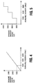
- Figure 5 illustrates a plot of another embodiment of a function that can be used to determine the amount of available memory space to allocate to the dynamic memory cache.
- This function is a staircase function that can be used to reduce the frequency of dynamic memory cache size adjustment.
- Changing dynamic memory cache sizes uses a particular amount of time to perform various clean-up tasks. For example, when a memory block that has been used as part of the dynamic memory cache is to be returned to the main memory array, the data in that memory block needs to be moved and the memory block erased.
- the SLC memory block of the dynamic memory cache is reallocated as an MLC memory block. Additionally, memory address pointers and other memory housekeeping tasks should also be performed to reallocate a dynamic memory cache block. Thus, it is typically desirable to reduce the frequency of dynamic memory cache size changes.
- the staircase function is one way of reducing the frequency of dynamic memory cache size changes. This can be seen in reference to the plot of Figure 5 . Unlike the embodiment of Figure 4 where the size change is performed in response to the slope of the line, the change of cache size does not occur in the stair step function until the present step reaches another particular threshold of available memory space.
- the initial dynamic memory cache size of 1 MB does not change until the available memory space reaches the 2 MB threshold. Then the dynamic memory cache size is increased to 2 MB.
- the illustrated available memory space and dynamic memory cache sizes are for purposes of illustration only as different amounts of available memory space can trigger reallocating different amounts of memory to the dynamic memory cache.
- alternate embodiments of the step function illustrated in Figure 5 can remain at the same dynamic memory cache size longer and/or allocate greater amounts of memory to the dynamic memory cache each time a threshold is reached.
- the cache size can be a function of if the amount of unused available memory is increasing or decreasing over a particular time period. For example, instead of a fixed percentage as illustrated in Figure 4 , if the available memory space size is increasing over a particular time period, the function might allocate a greater percentage of memory to the dynamic memory cache size than if the available memory space size was decreasing over the particular time period. In another embodiment, if the available memory space size is decreasing over a particular time period, the function might allocate a smaller percentage of memory to the dynamic memory cache size.
- a common pool of free (erased) blocks is used for both dynamic SLC cache and main MLC memory.
- free blocks are required (that is the number of free block fall below a first "start” threshold)
- dynamic SLC cache blocks are reclaimed and added to free pool until the number of free blocks is equal or more than a second "stop” threshold.
- the start and stop threshold may be adjusted dynamically. For example during foreground that is execution of command from host where we want to minimize reclaiming dynamic SLC cache blocks the stop threshold will not be high, but in background where there is no host commands the stop threshold will be set higher.
- the memory blocks that are allocated as dynamic memory cache blocks are contiguous memory blocks.
- the dynamic memory cache blocks are not contiguous.
- a bit map can be used to indicate and track which memory blocks are used as dynamic memory cache blocks.
- the bit indicating SLC or MLC may be combined with other information in the table for Logical to Physical mapping.
- a list can be maintained for both SLC and MLC blocks. Such a list is typically a linked list for ease of implementation.
- the bit indicating SLC or MLC may be combined with other information in the table for Logical to Physical mapping.
- a list is additionally maintained for both SLC and MLC blocks. Such a list is typically a linked list for ease of implementation.
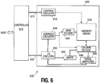
- Figure 6 illustrates a functional block diagram of a memory device 600.
- the memory device 600 is coupled to an external controller 610.
- the controller 610 may be a microprocessor or some other type of controller.
- the memory device 600 and the controller 610 form part of a memory system 620.
- the controller 610 can be coupled to a host and the controller 610 can be responsive to commands from the host.
- the memory device 600 includes an array 630 of memory cells (e.g., non-volatile memory cells).
- the memory array 630 is arranged in banks of word line rows and bit line columns. In one embodiment, the columns of the memory array 630 comprise series strings of memory cells.
- Address buffer circuitry 640 is provided to latch address signals provided through I/O circuitry 660. Address signals are received and decoded by a row decoder 644 and a column decoder 646 to access the memory array 630.
- the memory device 600 reads data in the memory array 630 by sensing voltage or current changes in the memory array columns using sense amplifier circuitry 650.
- the sense amplifier circuitry 650 in one embodiment, is coupled to read and latch a row of data from the memory array 630.
- Data input and output buffer circuitry 660 is included for bidirectional data communication as well as the address communication over a plurality of data connections 662 with the controller 610.
- Write circuitry 655 is provided to write data to the memory array.
- Memory control circuitry 670 decodes signals provided on control connections 672 from the controller 610. These signals are used to control the operations on the memory array 630, including data read, data write (program), and erase operations.
- the memory control circuitry 670 may be a state machine, a sequencer, or some other type of controller to generate the memory control signals.
- the memory control circuitry 670 and/or the external controller 610 are configured to control execution of the dynamic memory cache size adjustment.
- one or more embodiments of the method for dynamic memory cache size adjustment can provide increased capacity, performance (read or write) and/or reliability for user data in a memory device by dynamically adjusting the amount of memory allocated to a memory cache (e.g., used as SLC).
- a memory cache e.g., used as SLC
Description
- The present embodiments relate generally to memory and a particular embodiment relates to dynamic SLC cache in an MLC memory.
- Flash memory devices have developed into a popular source of non-volatile memory for a wide range of electronic applications. Flash memory devices typically use a one-transistor memory cell that allows for high memory densities, high reliability, and low power consumption. Common uses for flash memory include personal computers, flash drives, digital cameras, and cellular telephones. Program code and system data such as a basic input/output system (BIOS) are typically stored in flash memory devices for use in personal computer systems.
- A typical flash memory device is a type of memory in which the array of memory cells is typically organized into memory blocks that can be erased on a block-by-block basis (and reprogrammed on a page-by-page basis). Changes in a threshold voltage of each of the memory cells, through erasing or programming of a charge storage structure (e.g., floating gate or charge trap) or other physical phenomena (e.g., phase change or polarization), determine the data value programmed into each cell. The data in a cell of this type is determined by the presence or absence of the charge in the charge storage structure.
- A programming operation typically comprises a series of incrementally increasing programming pulses that are applied to a control gate of a memory cell being programmed in order to increase that particular memory cell's threshold voltage. Each memory cell can be programmed as single level cell (SLC) memory or multiple level cell (MLC) memory where the cell's threshold voltage (Vt) is indicative of the data value programmed into that cell. For example, in an SLC memory, a Vt of 2.5V might indicate a programmed cell while a Vt of-0.5V might indicate an erased cell. An MLC memory uses multiple Vt ranges that each indicates a different state. Multilevel cells can take advantage of the analog nature of a traditional flash cell by assigning a bit pattern to a specific Vt range. This technology permits the storage of data values representing two or more bits per cell, depending on the quantity of Vt ranges assigned to the cell.
- During programming of a block of memory cells, a fixed cache of memory cells is typically used to temporarily store data that is to be programmed into the block of memory cells. For example, in an MLC memory device, a fixed size SLC cache can be used to store data for programming into an MLC block of memory cells. This can improve memory reliability. The memory performance is also improved prior to the cache becoming near full, at that point part of the cache must be moved to MLC blocks to create more room in the cache, and the performance advantage of the cache will be diminished. The performance improvement is function of the size of the cache but has the drawback of reducing user capacity since a fixed portion of the memory is used as a SLC cache and cannot be used to store user data with the same efficiency as MLC.
- For further background, reference is made to the following publications:-
United States Patent Application Publication No.US 2009/235015 A1 to Hatsuda, K., et al. , discloses a method of dynamic memory cache size adjustment, the method comprising: determining available memory space in a memory array; and adjusting a size of a memory cache in the memory array responsive to the available memory space. It also discloses a memory system that includes a non-volatile memory constituted by blocks each of which is an erase unit constituted by pages each of which is a write/read unit constituted by memory cells; a random access memory temporarily storing data which is written in or read from the non-volatile memory; and a controller controlling the non-volatile memory and the random access memory, wherein the non-volatile memory includes a main memory area in which the block is divided into first management units respectively specified by logical addresses and a cache area in which the block is divided into second management units respectively specified by logical addresses, a data capacity of one of the second management units is smaller than that of one of the first management units,; and the controller changes number of the blocks in the main memory area and number of the blocks in the cache area in the non-volatile memory. - United States Patent Application Publication No.
US 2007/174551 A1 to Cornwell, M. J., et al. , discloses a dynamic memory cache wherein a microcontroller modifies the caching policy based on data, which may state the amount of cache space available, received from an external source. The caching policy may include a cache threshold, which may be an address or an indicator that specifies an amount of memory. The dynamic memory cache size adjustment is enabled or disabled based on a particular file system being supported. The dynamic memory cache size adjustment may be disabled if either the particular file system does not support dynamic memory cache size adjustment or a command is not received that supports deletion of a range of logical block addresses of the memory device. It is determined if a file system of the memory device is supported -for example, it is determined if a command is received that supports a protocol that allows deletion of a range of logical block addresses. - United States Patent Application Publication No.
US 2010/172179 A1, to Gorobets, S. A., et al. , for example, discloses size adjustment of a memory cache composed of single-level cache 'SLC' cells. Techniques for the management of spare blocks in re-programmable non-volatile memory system, such as a flash EEPROM system, are presented. In one set of techniques, for a memory partitioned into two sections (for example a binary section and a multi-state section), where blocks of one section are more prone to error, spare blocks can be transferred from the more error prone partition to the less error prone partition. In another set of techniques for a memory partitioned into two sections, blocks which fail in the more error prone partition are transferred to serve as spare blocks in the other partition. In a complementary set of techniques, a 1-bit time stamp is maintained for free blocks to determine whether the block has been written recently; Other techniques allow for spare blocks to be managed by way of a logical to physical conversion table by assigning them logical addresses that exceed the logical address space of which a host is aware. - United States Patent Application Publication No.
US 2010-0122016 A1 to Marotta, G., et al., discloses dynamic block allocations in NAND flash memory between single-level cells 'SLC' and multi-level cells 'MLC' based on characteristics. In one embodiment, a memory controller dynamically switches between programming and/or reprogramming blocks between SLC mode and MLC mode based on the amount of memory available for use. When memory usage is low, SLC mode is used. When memory usage is high, MLC mode is used. Dynamic block allocation allows a memory controller to obtain the performance and reliability benefits of SLC mode while retaining the space saving benefits of MLC mode. - United States Patent Application Publication No.
US 2010-0042773 A1 to Yeh, C., discloses a flash memory storage system that includes a controller, a connector, a cache memory, a SLC NAND flash memory and a MLC NAND flash memory. When the controller receives data to be written into the MLC NAND flash memory from a host system, the data is temporarily stored in the cache memory first and then is written into the MLC NAND flash memory from the cache memory. And, the controller may backup the data stored in the cache memory to the SLC NAND flash memory. Accordingly, it is possible to reduce a response time for a flush command, thereby improving a performance of the flash memory storage system. - United States Patent Application Publication No.
US 2007-0285980 A1 to Takahiro, S., et al., discloses a semiconductor memory that includes a memory cell array having a first region that has a plurality of memory cells each capable of storing n-bit data (n is a natural number) and a second region that has a plurality of memory cells each capable of storing k-bit data (k>n: k is a natural number), a data storage circuit which includes a plurality of data caches, and a control circuit which controls the memory cell array and the data storage circuit in such a manner that the k-bit data read from the k/n number of memory cells in the first region are stored into the data storage circuit and the k-bit data are stored into the memory cells in the second region. - Japanese Patent Application Publication No.
2009-217630 - For the reasons stated above and for other reasons that will become apparent to those skilled in the art upon reading and understanding the present specification, there is a need in the art for a more efficient way to temporarily store data during programming.
- The present invention is defined in the appended independent claims to which reference should be made. Advantageous features are set out in the appended dependent claims.
- The embodiments or examples of the following description which are not covered by the appended claims are considered as not being part of the invention.
-
-
Figure 1 shows a block diagram of one embodiment of a memory array in a memory device that incorporates a memory cache. -
Figure 2 shows a schematic diagram of one embodiment of a portion of a memory array in accordance with the block diagram ofFigure 1 . -
Figure 3 shows flow chart of one embodiment of a method for dynamic cache size adjustment. -
Figure 4 shows a plot of one embodiment of one function for determining when to adjust the cache size. -
Figure 5 shows a plot of another embodiment of a function for determining when to adjust the cache size. -
Figure 6 shows a block diagram of one embodiment of a memory system. - In the following detailed description, reference is made to the accompanying drawings that form a part hereof and in which is shown, by way of illustration, specific embodiments. In the drawings, like numerals describe substantially similar components throughout the several views. Other embodiments may be utilized and structural, logical, and electrical changes may be made without departing from the scope of the appended claims. The following detailed description is, therefore, not to be taken in a limiting sense.
-
Figure 1 illustrates a block diagram of one embodiment ofmemory array 100 of a memory device that incorporateddynamic memory cache 102. Thememory array 100 is partitioned and includes a first partition; hereinafter referred to as main MLC memory wherein cells in that partition are programmed in MLC mode and asecond partition 102 herein after referred to as dynamic SLC memory cache wherein cells in that partition are programmed in SLC mode. In one embodiment the blocks allocated to main memory in thememory array 100 are used as MLC and the blocks allocated todynamic memory cache 102 are used as SLC. In a dynamic memory cache the allocation of blocks changes dynamically and is not fixed, a block may remain MLC or SLC or switch between being used as MLC or SLC. Without loss of generality, the blocks used for thecache 102 are referred to as SLC cache blocks and the blocks used for storing user data are referred to as MLC main memory blocks. - Typical prior art memory caches are fixed in size and are always enabled so that a portion of the memory array is always dedicated to a temporary data cache, reducing the amount of memory available for storing user data. The
dynamic data cache 102 ofFigure 1 is adjusted in size dynamically, depending on the free space available, and may not always be enabled. Thus, thedynamic memory cache 102 can be adjusted such that it does not take up more memory than is necessary to accomplish the cache function wherein the cache size is dynamically adjusted. Another feature of present invention is that partition of memory to MLC and SLC can be at array or block level. Yet another feature of present invention is that the arrays or blocks in a partition are not required to be continuous. In some systems the data is always first written to cache. In other systems only some type of data is written to cache, for example data less than a page size. In systems with fixed or dynamic memory cache some events will trigger moving the valid data from the cache to the main memory blocks (in some systems both valid and invalid data in the cache may be moved). Such events include the number of free blocks in cache falling below a threshold. When a block in cache is moved to main memory the block is erased and it is reclaimed. Similarly, blocks in main memory containing old and new data can be reclaimed by moving the new data to another block in main memory and then erasing the old block. - The dynamic
SLC memory cache 102 uses a variable number of blocks of memory of thememory array 100 to temporarily store data that is to be programmed into themain memory array 100. For example, the dynamicSLC memory cache 102 can store all pages (lower and upper) of data until the upper page of data is successfully programmed in the mainMLC memory array 100. This can reduce corruption of a previously programmed lower page of the mainMLC memory array 100 if a power failure occurs during upper page programming. In one embodiment, data is stored in thedynamic memory cache 102 blocks in SLC and when all pages required for programming a page in an MLC block are available (in dynamic memory cache 102) then the data is moved to a block inmain memory array 100, so that thecache 102 can store all pages of data required until one page of the MLCmain memory array 100 is programmed. For example, the SLCdynamic memory cache 102 can store a lower page of data until an upper page of the MLCmain memory array 100 is successfully programmed. This can reduce corruption of a previously programmed lower page of the MLCmain memory array 100 if a power failure occurs during upper page programming. -
Figure 2 illustrates a schematic diagram of one embodiment of a portion of the NANDarchitecture memory array 201, as illustrated inFigure 1 , comprising series strings of non-volatile memory cells. The present embodiments of the memory array are not limited to the illustrated NAND architecture. Alternate embodiments can use NOR or other architectures as well. - The
memory array 201 comprises an array of non-volatile memory cells (e.g., floating gate) arranged in columns such as series strings 204, 205. Each of the cells is coupled drain to source in eachseries string multiple series strings - Each series string 204,205 of memory cells is coupled to a
source line 206 by a sourceselect gate 216, 217 (e.g., transistor) and to an individual bit line BL_E, BL _0 by a drain select gate 212,213 (e.g., transistor). The source select gates 216,217 are controlled by
a source select gate control line SG(S) 218 coupled to their control gates. The drainselect gates -
Figure 3 illustrates a flow chart of one embodiment of a method for dynamically adjusting the size of the dynamic memory cache illustrated inFigure 1 . Since some file systems might not be recognized, the method determines if the file system implemented (e.g., installed, executed) on the memory device is one that is supported 300. As is well known in the art, a file system (e.g., File Allocation Table (FAT), New Technology File System (NTFS)) is a method for storing and organizing computer files and their data. It organizes these files into a database for the storage, organization, manipulation, and retrieval by a computer's operating system. - If the file system does not support dynamic
cache size adjustment 300, the dynamic memory cache adjustment is disabled 310. Dynamic memory cache size adjustment might still be implemented if the memory device supports any command protocol that allows deletion of ranges of logical block addresses in order to implement the dynamic changing of the memory cache size. One such protocol known in the art is typically generically referred to as a TRIM protocol. It is thus determined if a TRIM command has been received 302. Thisstep 302 is repeated until the TRIM command is received. Once the TRIM command is received 302, the dynamic memory cache is enabled 304. - Since the size of the dynamic memory cache is adjusted in response to the available memory space in the main memory array, the available memory space in the main memory array is determined 306. The amount of available memory space can change constantly. In one embodiment, the amount of available memory space in the main memory array can be determined after every write or erase operation. In other embodiments, the amount of available memory space can be determined periodically or at random times. Available memory space can include both erased memory that is not targeted for immediate use as well as memory that has not yet been erased but the data stored in the memory is old and no longer valid. In yet another embodiment, the amount of available memory is adjusted in response to a received TRIM command (if TRIM is supported) or, in case of known file systems, when clusters are deallocated or written.
- In systems with fixed or dynamic memory cache, some
events will trigger moving the valid data (or, optionally, valid and invalid data) from the dynamic SLC cache memory to the main MLC memory blocks. Such events include the number of free blocks in cache falling below a threshold. When a block in dynamic SLC cache is moved to main MLC memory the block is erased and it is reclaimed and added to the pool of free blocks. Similarly, blocks in main MLC memory containing old and new data can be reclaimed by moving only the valid data to another block in main MLC memory and then erasing the old block. - The size of the dynamic memory cache is then adjusted in response to the
available memory space 308. The size of the dynamic memory cache can be a percentage of the available memory space, all of the available memory space, or a certain number of blocks of the available memory space. In one embodiment, the percentage of the available memory space used can also be dynamically changed. For example, only 50% of the available memory space might be allocated to the dynamic memory cache at one time and, at a later time, 90% of the available memory space might be allocated to the dynamic memory cache. Such dynamic allocation of the percentage of available memory space can be performed as often as desired. -
Figure 4 illustrates a plot of one embodiment of a function that can be used to determine the amount of available memory space to allocate to the dynamic memory cache. This function is a linear ramped function in which a fixed percentage (e.g., 50%) of the available memory space is allocated to the dynamic memory cache. - This plot includes the available memory space along the x-axis and the size of the dynamic memory cache along the y-axis. The memory size values on both the x and y-axes, in this and the following embodiments, are for purposes of illustration only as the present embodiments are not limited to any certain values. The slope of the line determines the percentage of available memory space that is allocated to the dynamic memory cache. The illustrated example shows a 50% embodiment.
-
Figure 5 illustrates a plot of another embodiment of a function that can be used to determine the amount of available memory space to allocate to the dynamic memory cache. This function is a staircase function that can be used to reduce the frequency of dynamic memory cache size adjustment. - Changing dynamic memory cache sizes uses a particular amount of time to perform various clean-up tasks. For example, when a memory block that has been used as part of the dynamic memory cache is to be returned to the main memory array, the data in that memory block needs to be moved and the memory block erased. In one embodiment, the SLC memory block of the dynamic memory cache is reallocated as an MLC memory block. Additionally, memory address pointers and other memory housekeeping tasks should also be performed to reallocate a dynamic memory cache block. Thus, it is typically desirable to reduce the frequency of dynamic memory cache size changes.
- The staircase function is one way of reducing the frequency of dynamic memory cache size changes. This can be seen in reference to the plot of
Figure 5 . Unlike the embodiment ofFigure 4 where the size change is performed in response to the slope of the line, the change of cache size does not occur in the stair step function until the present step reaches another particular threshold of available memory space. - For example, the initial dynamic memory cache size of 1 MB does not change until the available memory space reaches the 2 MB threshold. Then the dynamic memory cache size is increased to 2 MB. The illustrated available memory space and dynamic memory cache sizes are for purposes of illustration only as different amounts of available memory space can trigger reallocating different amounts of memory to the dynamic memory cache. Similarly, alternate embodiments of the step function illustrated in
Figure 5 can remain at the same dynamic memory cache size longer and/or allocate greater amounts of memory to the dynamic memory cache each time a threshold is reached. - In yet another embodiment of a function for determining the amount of available memory space to allocate to the dynamic memory cache, the cache size can be a function of if the amount of unused available memory is increasing or decreasing over a particular time period. For example, instead of a fixed percentage as illustrated in
Figure 4 , if the available memory space size is increasing over a particular time period, the function might allocate a greater percentage of memory to the dynamic memory cache size than if the available memory space size was decreasing over the particular time period. In another embodiment, if the available memory space size is decreasing over a particular time period, the function might allocate a smaller percentage of memory to the dynamic memory cache size. - In yet another embodiment, to minimize overhead and dynamically allocating most of free space to cache a common pool of free (erased) blocks is used for both dynamic SLC cache and main MLC memory. As free blocks are required (that is the number of free block fall below a first "start" threshold) dynamic SLC cache blocks are reclaimed and added to free pool until the number of free blocks is equal or more than a second "stop" threshold. The start and stop threshold may be adjusted dynamically. For example during foreground that is execution of command from host where we want to minimize reclaiming dynamic SLC cache blocks the stop threshold will not be high, but in background where there is no host commands the stop threshold will be set higher.
- In one embodiment, the memory blocks that are allocated as dynamic memory cache blocks are contiguous memory blocks. In another embodiment, the dynamic memory cache blocks are not contiguous. In such an embodiment, a bit map can be used to indicate and track which memory blocks are used as dynamic memory cache blocks. In another embodiment, the bit indicating SLC or MLC may be combined with other information in the table for Logical to Physical mapping. In another embodiment, a list can be maintained for both SLC and MLC blocks. Such a list is typically a linked list for ease of implementation. In another embodiment the bit indicating SLC or MLC may be combined with other information in the table for Logical to Physical mapping. In another embodiment, a list is additionally maintained for both SLC and MLC blocks. Such a list is typically a linked list for ease of implementation.
-
Figure 6 illustrates a functional block diagram of amemory device 600. Thememory device 600 is coupled to anexternal controller 610. Thecontroller 610 may be a microprocessor or some other type of controller. Thememory device 600 and thecontroller 610 form part of amemory system 620. Thecontroller 610 can be coupled to a host and thecontroller 610 can be responsive to commands from the host. - The
memory device 600 includes anarray 630 of memory cells (e.g., non-volatile memory cells). Thememory array 630 is arranged in banks of word line rows and bit line columns. In one embodiment, the columns of thememory array 630 comprise series strings of memory cells. -
Address buffer circuitry 640 is provided to latch address signals provided through I/O circuitry 660. Address signals are received and decoded by arow decoder 644 and acolumn decoder 646 to access thememory array 630. - The
memory device 600 reads data in thememory array 630 by sensing voltage or current changes in the memory array columns usingsense amplifier circuitry 650. Thesense amplifier circuitry 650, in one embodiment, is coupled to read and latch a row of data from thememory array 630. Data input andoutput buffer circuitry 660 is included for bidirectional data communication as well as the address communication over a plurality ofdata connections 662 with thecontroller 610. Writecircuitry 655 is provided to write data to the memory array. -
Memory control circuitry 670 decodes signals provided oncontrol connections 672 from thecontroller 610. These signals are used to control the operations on thememory array 630, including data read, data write (program), and erase operations. Thememory control circuitry 670 may be a state machine, a sequencer, or some other type of controller to generate the memory control signals. In one embodiment, thememory control circuitry 670 and/or theexternal controller 610 are configured to control execution of the dynamic memory cache size adjustment. - The memory device illustrated in
Figure 6 has been simplified to facilitate a basic understanding of the features of the memory. A more detailed understanding of internal circuitry and functions of flash memories are known to those skilled in the art. - In summary, one or more embodiments of the method for dynamic memory cache size adjustment can provide increased capacity, performance (read or write) and/or reliability for user data in a memory device by dynamically adjusting the amount of memory allocated to a memory cache (e.g., used as SLC).
- Although specific embodiments have been illustrated and described herein, it will be appreciated by those of ordinary skill in the art that any arrangement falling within the scope of the appended claims and that is calculated to achieve the same purpose may be substituted for the specific embodiments shown. Many adaptations of the invention, falling within the scope of the appended claims, will be apparent to those of ordinary skill in the art. Accordingly, this application is intended to cover any adaptations or variations of the invention that fall within the scope of the appended claims.
Claims (10)
- A method for dynamic memory cache size adjustment, the method characterised by :disabling (310) dynamic adjustment of a size of a memory cache (102) in a memory array (100; 630) of a memory device (600) in response to determining that a file system on the memory device (600) does not support dynamic cache size adjustment;enabling (304) the disabled dynamic adjustment of the size of the memory cache (102) in response to receiving a command that is supported by the memory device and that allows deletion of a range of logical block addresses of the memory device (600);determining (306) a size of available memory space in the memory array (100; 630) of the memory device (600); andadjusting (308) the size of the memory cache (102) in the memory array (100; 630) responsive to the determined size of the available memory space.
- The method of claim 1 wherein the available memory space is one of erased memory that is not targeted for use or unerased memory that stores data that is not valid.
- The method of claim 1 wherein the size of the memory cache (102) is a percentage of the determined size of the available memory space and further including dynamically adjusting the percentage.
- The method of claim 1 wherein the size of the memory cache (102) is a percentage of the determined size of the available memory space and wherein the percentage of the determined size of the available memory space is a variable percentage of the determined size of the available memory space.
- The method of claim 1 wherein adjusting the size of the memory cache (102) comprises allocating a first number of blocks of the memory array (100; 630) for use as the memory cache (102) and allocating a second number of blocks of the memory array (100, 630) for use as main memory.
- A memory device (600) comprising:an array (100; 630) of memory cells comprising a memory cache (102);memory control circuitry (670) coupled to the array (100; 630) of memory cells; anda file system;wherein the control circuitry (670) is configured to disable (310) dynamic adjustment of a size of the memory cache (102) in response to determining that the file system does not support dynamic cache size adjustment;wherein the control circuitry (670) is configured to enable (304) the disabled dynamic adjustment of the size of the memory cache in response to a received command that is supported by the memory device and that allows deletion of a range of logical block addresses of the memory device (600); andwherein the control circuitry (670) is configured to determine (306) a size of available memory space in the array of memory cells and adjust (308) the size of the memory cache (102) responsive to the determined size of the available memory space.
- The memory device of claim 6 wherein adjusting (308) the size of the memory cache (102) comprises adjusting a number of blocks of the array (100; 630) whose memory cells are programmed as SLC cells.
- The memory device of claim 6 wherein the plurality of available memory thresholds forms a step function of available memory.
- The memory device of claim 8 wherein the memory control circuitry (670) is configured to increase the size of the memory cache (102) responsive to determined size of the available memory space reaching one of a plurality of available memory thresholds.
- The memory device of claim 6 wherein the memory control circuitry (670) is configured to adjust the size of the memory cache (102) dynamically as a function of whether the determined size of the available memory space is increasing or decreasing over a particular time period.
Applications Claiming Priority (2)
| Application Number | Priority Date | Filing Date | Title |
|---|---|---|---|
| US13/118,721 US8886911B2 (en) | 2011-05-31 | 2011-05-31 | Dynamic memory cache size adjustment in a memory device |
| PCT/US2012/036923 WO2012166304A2 (en) | 2011-05-31 | 2012-05-08 | Dynamic memory cache size adjustment in a memory device |
Publications (3)
| Publication Number | Publication Date |
|---|---|
| EP2715548A2 EP2715548A2 (en) | 2014-04-09 |
| EP2715548A4 EP2715548A4 (en) | 2014-12-17 |
| EP2715548B1 true EP2715548B1 (en) | 2019-10-30 |
Family
ID=47260161
Family Applications (1)
| Application Number | Title | Priority Date | Filing Date |
|---|---|---|---|
| EP12794100.3A Active EP2715548B1 (en) | 2011-05-31 | 2012-05-08 | Dynamic memory cache size adjustment in a memory device |
Country Status (7)
| Country | Link |
|---|---|
| US (2) | US8886911B2 (en) |
| EP (1) | EP2715548B1 (en) |
| JP (1) | JP5808853B2 (en) |
| KR (1) | KR101547418B1 (en) |
| CN (1) | CN103562883B (en) |
| TW (1) | TWI456392B (en) |
| WO (1) | WO2012166304A2 (en) |
Families Citing this family (69)
| Publication number | Priority date | Publication date | Assignee | Title |
|---|---|---|---|---|
| US8880977B2 (en) | 2011-07-22 | 2014-11-04 | Sandisk Technologies Inc. | Systems and methods of storing data |
| KR20130060791A (en) * | 2011-11-30 | 2013-06-10 | 삼성전자주식회사 | Memory system, data storage device, memory card, and ssd including wear level control logic |
| US9348741B1 (en) * | 2011-12-19 | 2016-05-24 | Western Digital Technologies, Inc. | Systems and methods for handling write data access requests in data storage devices |
| US20130219146A1 (en) * | 2012-02-16 | 2013-08-22 | Micron Technology, Inc. | Method, device and system for a configurable address space for non-volatile memory |
| US8990477B2 (en) * | 2012-04-19 | 2015-03-24 | Sandisk Technologies Inc. | System and method for limiting fragmentation |
| KR102147359B1 (en) * | 2012-06-29 | 2020-08-24 | 삼성전자 주식회사 | Method for managing non-volatile memory device, and non-volatile memory device |
| US9128845B2 (en) * | 2012-07-30 | 2015-09-08 | Hewlett-Packard Development Company, L.P. | Dynamically partition a volatile memory for a cache and a memory partition |
| KR20140069659A (en) * | 2012-11-29 | 2014-06-10 | 성균관대학교산학협력단 | File System For Flash Memory |
| GB2511325A (en) * | 2013-02-28 | 2014-09-03 | Ibm | Cache allocation in a computerized system |
| US9569352B2 (en) * | 2013-03-14 | 2017-02-14 | Sandisk Technologies Llc | Storage module and method for regulating garbage collection operations based on write activity of a host |
| KR102121333B1 (en) * | 2013-10-28 | 2020-06-11 | 에스케이하이닉스 주식회사 | Semiconductor system and operating method thereof |
| US9558124B2 (en) * | 2013-11-08 | 2017-01-31 | Seagate Technology Llc | Data storage system with passive partitioning in a secondary memory |
| US9471254B2 (en) | 2014-04-16 | 2016-10-18 | Sandisk Technologies Llc | Storage module and method for adaptive burst mode |
| US10430328B2 (en) * | 2014-09-16 | 2019-10-01 | Sandisk Technologies Llc | Non-volatile cache and non-volatile storage medium using single bit and multi bit flash memory cells or different programming parameters |
| US10452280B2 (en) * | 2014-10-03 | 2019-10-22 | International Business Machines Corporation | Hybrid storage system employing reconfigurable memory |
| US11347637B2 (en) | 2014-10-30 | 2022-05-31 | Kioxia Corporation | Memory system and non-transitory computer readable recording medium |
| US10102118B2 (en) * | 2014-10-30 | 2018-10-16 | Toshiba Memory Corporation | Memory system and non-transitory computer readable recording medium |
| US9542328B2 (en) * | 2015-01-26 | 2017-01-10 | International Business Machines Corporation | Dynamically controlling a file system write cache |
| WO2016122466A1 (en) * | 2015-01-27 | 2016-08-04 | Hewlett Packard Enterprise Development Lp | Transferring a variable data payload |
| WO2016182753A1 (en) * | 2015-05-08 | 2016-11-17 | Sandisk Technologies Llc | Data mapping for non-volatile storage |
| US10096355B2 (en) * | 2015-09-01 | 2018-10-09 | Sandisk Technologies Llc | Dynamic management of programming states to improve endurance |
| US20170075812A1 (en) * | 2015-09-16 | 2017-03-16 | Intel Corporation | Technologies for managing a dynamic read cache of a solid state drive |
| US10140030B2 (en) | 2015-11-02 | 2018-11-27 | International Business Machines Corporation | Dynamic modulation of cache memory |
| US10037149B2 (en) * | 2016-06-17 | 2018-07-31 | Seagate Technology Llc | Read cache management |
| US9990158B2 (en) | 2016-06-22 | 2018-06-05 | Sandisk Technologies Llc | Storage system and method for burst mode management using transfer RAM |
| US10552327B2 (en) * | 2016-08-23 | 2020-02-04 | Apple Inc. | Automatic cache partitioning |
| US10359933B2 (en) * | 2016-09-19 | 2019-07-23 | Micron Technology, Inc. | Memory devices and electronic systems having a hybrid cache including static and dynamic caches with single and multiple bits per cell, and related methods |
| KR101948988B1 (en) * | 2016-12-12 | 2019-02-15 | 주식회사 엘지유플러스 | Method and Apparatus For Executing File Using Cache |
| US10095626B2 (en) | 2017-03-10 | 2018-10-09 | Toshiba Memory Corporation | Multibit NAND media using pseudo-SLC caching technique |
| US10049047B1 (en) | 2017-03-10 | 2018-08-14 | Toshiba Memory Corporation | Multibit NAND media using pseudo-SLC caching technique |
| KR101961547B1 (en) * | 2017-04-28 | 2019-07-05 | 주식회사 엘지유플러스 | Apparatus for processing virtual file system and method thereof |
| TWI630540B (en) * | 2017-07-13 | 2018-07-21 | 慧榮科技股份有限公司 | Data storage device and method for operating non-volatile memory |
| US10347329B2 (en) | 2017-08-29 | 2019-07-09 | Micron Technology, Inc. | Reflow protection |
| US10545685B2 (en) | 2017-08-30 | 2020-01-28 | Micron Technology, Inc. | SLC cache management |
| US10572388B2 (en) | 2017-08-30 | 2020-02-25 | Micron Technology, Inc. | Managed NVM adaptive cache management |
| US10522229B2 (en) | 2017-08-30 | 2019-12-31 | Micron Technology, Inc. | Secure erase for data corruption |
| US10096380B1 (en) | 2017-08-31 | 2018-10-09 | Micron Technology, Inc. | Erase page check |
| US10579288B2 (en) | 2017-08-31 | 2020-03-03 | Micron Technology, Inc. | Prioritized security |
| JP2022062264A (en) * | 2017-09-22 | 2022-04-19 | キオクシア株式会社 | Memory system |
| JP7030463B2 (en) * | 2017-09-22 | 2022-03-07 | キオクシア株式会社 | Memory system |
| US10409726B2 (en) | 2017-10-30 | 2019-09-10 | Micron Technology, Inc. | Dynamic L2P cache |
| US10908832B2 (en) | 2017-10-31 | 2021-02-02 | Micron Technology, Inc. | Common pool management |
| US10521146B1 (en) | 2017-11-09 | 2019-12-31 | Micron Technology, Inc. | UFS based idle time garbage collection management |
| US10229735B1 (en) * | 2017-12-22 | 2019-03-12 | Intel Corporation | Block management for dynamic single-level cell buffers in storage devices |
| CN108287794A (en) * | 2018-01-26 | 2018-07-17 | 国科美国研究实验室 | The dynamic management approach of nand flash memory |
| KR102535104B1 (en) * | 2018-03-19 | 2023-05-23 | 에스케이하이닉스 주식회사 | Storage device and operating method thereof |
| US10909040B2 (en) | 2018-04-19 | 2021-02-02 | Intel Corporation | Adaptive calibration of nonvolatile memory channel based on platform power management state |
| CN108572924B (en) * | 2018-04-20 | 2021-10-08 | 华中科技大学 | Request processing method of 3D MLC flash memory device |
| US11341048B2 (en) | 2018-10-29 | 2022-05-24 | Micron Technology, Inc. | SLC cache allocation |
| US20200183838A1 (en) * | 2018-12-10 | 2020-06-11 | International Business Machines Corporation | Dynamic cache resize taking into account underlying raid characteristics |
| KR20200091679A (en) | 2019-01-23 | 2020-07-31 | 에스케이하이닉스 주식회사 | Memory system and operation method thereof |
| US10983829B2 (en) | 2019-07-12 | 2021-04-20 | Micron Technology, Inc. | Dynamic size of static SLC cache |
| US11237732B2 (en) * | 2019-08-06 | 2022-02-01 | Intel Corporation | Method and apparatus to improve write bandwidth of a block-based multi-level cell nonvolatile memory |
| US20210042236A1 (en) * | 2019-08-06 | 2021-02-11 | Micron Technology, Inc. | Wear leveling across block pools |
| US10950313B1 (en) | 2019-08-28 | 2021-03-16 | Micron Technology, Inc. | Responding to changes in available power supply |
| KR20210057254A (en) | 2019-11-11 | 2021-05-21 | 삼성전자주식회사 | Storage device and operating method therof |
| US11656773B2 (en) * | 2020-04-28 | 2023-05-23 | EMC IP Holding Company LLC | Automatic management of file system capacity using predictive analytics for a storage system |
| US11740789B2 (en) | 2020-05-18 | 2023-08-29 | EMC IP Holding Company LLC | Automated storage capacity provisioning using machine learning techniques |
| US11366754B2 (en) * | 2020-07-28 | 2022-06-21 | Micron Technology, Inc. | Adjustable buffer memory space |
| JP2022030146A (en) * | 2020-08-06 | 2022-02-18 | キオクシア株式会社 | Memory system and write control method |
| US11449229B2 (en) | 2020-10-20 | 2022-09-20 | Red Hat, Inc. | Dynamically resizing a region of volatile memory based on a charge level of a backup battery supply |
| US11256620B1 (en) * | 2020-11-13 | 2022-02-22 | Micron Technology, Inc. | Cache management based on memory device over-provisioning |
| US20220188242A1 (en) * | 2020-12-11 | 2022-06-16 | Micron Technology, Inc. | Multi-tier cache for a memory system |
| US11908504B2 (en) | 2021-04-13 | 2024-02-20 | Seagate Technology Llc | Front end buffer having ferroelectric field effect transistor (FeFET) based memory |
| CN113805812B (en) * | 2021-09-22 | 2024-03-05 | 深圳宏芯宇电子股份有限公司 | Cache management method, device, equipment and storage medium |
| TWI793932B (en) | 2021-12-21 | 2023-02-21 | 建興儲存科技股份有限公司 | Solid state storage device and associated write control method |
| US20240061589A1 (en) * | 2022-08-17 | 2024-02-22 | Micron Technology, Inc. | Code rate as function of logical saturation |
| CN115168247B (en) * | 2022-09-02 | 2022-12-02 | 北京登临科技有限公司 | Method for dynamically sharing memory space in parallel processor and corresponding processor |
| TWI814666B (en) * | 2022-12-14 | 2023-09-01 | 慧榮科技股份有限公司 | Data storage device and method for dynamically determining buffer size |
Family Cites Families (28)
| Publication number | Priority date | Publication date | Assignee | Title |
|---|---|---|---|---|
| US7127560B2 (en) * | 2003-10-14 | 2006-10-24 | International Business Machines Corporation | Method of dynamically controlling cache size |
| US7752391B2 (en) * | 2006-01-20 | 2010-07-06 | Apple Inc. | Variable caching policy system and method |
| JP4805696B2 (en) * | 2006-03-09 | 2011-11-02 | 株式会社東芝 | Semiconductor integrated circuit device and data recording method thereof |
| JP2007305210A (en) * | 2006-05-10 | 2007-11-22 | Toshiba Corp | Semiconductor storage device |
| US7711890B2 (en) * | 2006-06-06 | 2010-05-04 | Sandisk Il Ltd | Cache control in a non-volatile memory device |
| US8489817B2 (en) * | 2007-12-06 | 2013-07-16 | Fusion-Io, Inc. | Apparatus, system, and method for caching data |
| JP2009003569A (en) * | 2007-06-19 | 2009-01-08 | Toshiba Corp | Semiconductor memory |
| JP2009043030A (en) * | 2007-08-09 | 2009-02-26 | Hitachi Ltd | Storage system |
| US8484432B2 (en) * | 2008-03-11 | 2013-07-09 | Kabushiki Kaisha Toshiba | Memory system |
| JP4558054B2 (en) * | 2008-03-11 | 2010-10-06 | 株式会社東芝 | Memory system |
| KR101456592B1 (en) | 2008-06-17 | 2014-10-31 | 삼성전자주식회사 | Multi-bit flash memory device and analysis method of flag cells for the same |
| US8843691B2 (en) | 2008-06-25 | 2014-09-23 | Stec, Inc. | Prioritized erasure of data blocks in a flash storage device |
| US20100017556A1 (en) | 2008-07-19 | 2010-01-21 | Nanostar Corporationm U.S.A. | Non-volatile memory storage system with two-stage controller architecture |
| JP2010026933A (en) * | 2008-07-23 | 2010-02-04 | Toshiba Corp | Memory system and host device |
| TWI385516B (en) * | 2008-08-12 | 2013-02-11 | Phison Electronics Corp | Flash memory storage system and data writing method thereof |
| US8407400B2 (en) * | 2008-11-12 | 2013-03-26 | Micron Technology, Inc. | Dynamic SLC/MLC blocks allocations for non-volatile memory |
| US8040744B2 (en) * | 2009-01-05 | 2011-10-18 | Sandisk Technologies Inc. | Spare block management of non-volatile memories |
| US8244960B2 (en) * | 2009-01-05 | 2012-08-14 | Sandisk Technologies Inc. | Non-volatile memory and method with write cache partition management methods |
| US20100332922A1 (en) * | 2009-06-30 | 2010-12-30 | Mediatek Inc. | Method for managing device and solid state disk drive utilizing the same |
| US8479080B1 (en) * | 2009-07-12 | 2013-07-02 | Apple Inc. | Adaptive over-provisioning in memory systems |
| US20110107042A1 (en) * | 2009-11-03 | 2011-05-05 | Andrew Herron | Formatting data storage according to data classification |
| US8677054B1 (en) * | 2009-12-16 | 2014-03-18 | Apple Inc. | Memory management schemes for non-volatile memory devices |
| US8402243B2 (en) * | 2010-02-25 | 2013-03-19 | Apple Inc. | Dynamically allocating number of bits per cell for memory locations of a non-volatile memory |
| US20110252187A1 (en) * | 2010-04-07 | 2011-10-13 | Avigdor Segal | System and method for operating a non-volatile memory including a portion operating as a single-level cell memory and a portion operating as a multi-level cell memory |
| US9021177B2 (en) * | 2010-04-29 | 2015-04-28 | Densbits Technologies Ltd. | System and method for allocating and using spare blocks in a flash memory |
| US9158695B2 (en) * | 2011-08-09 | 2015-10-13 | Seagate Technology Llc | System for dynamically adaptive caching |
| US9152548B2 (en) * | 2012-01-17 | 2015-10-06 | Vmware, Inc. | Controlling access to a privileged resource in user-mode system level mobile virtualization using a ptrace () system call |
| US9804960B2 (en) * | 2013-03-14 | 2017-10-31 | Western Digital Technologies, Inc. | Overprovision capacity in a data storage device |
-
2011
- 2011-05-31 US US13/118,721 patent/US8886911B2/en active Active
-
2012
- 2012-05-08 JP JP2014513523A patent/JP5808853B2/en active Active
- 2012-05-08 KR KR1020137033029A patent/KR101547418B1/en active IP Right Grant
- 2012-05-08 CN CN201280025689.2A patent/CN103562883B/en active Active
- 2012-05-08 WO PCT/US2012/036923 patent/WO2012166304A2/en active Application Filing
- 2012-05-08 EP EP12794100.3A patent/EP2715548B1/en active Active
- 2012-05-25 TW TW101118861A patent/TWI456392B/en active
-
2014
- 2014-10-09 US US14/510,179 patent/US9195604B2/en active Active
Non-Patent Citations (1)
| Title |
|---|
| None * |
Also Published As
| Publication number | Publication date |
|---|---|
| WO2012166304A2 (en) | 2012-12-06 |
| JP5808853B2 (en) | 2015-11-10 |
| KR101547418B1 (en) | 2015-08-25 |
| WO2012166304A3 (en) | 2013-01-24 |
| US9195604B2 (en) | 2015-11-24 |
| TW201301031A (en) | 2013-01-01 |
| EP2715548A2 (en) | 2014-04-09 |
| KR20140016377A (en) | 2014-02-07 |
| EP2715548A4 (en) | 2014-12-17 |
| US8886911B2 (en) | 2014-11-11 |
| US20150026416A1 (en) | 2015-01-22 |
| JP2014515531A (en) | 2014-06-30 |
| CN103562883B (en) | 2016-05-18 |
| TWI456392B (en) | 2014-10-11 |
| US20120311293A1 (en) | 2012-12-06 |
| CN103562883A (en) | 2014-02-05 |
Similar Documents
| Publication | Publication Date | Title |
|---|---|---|
| EP2715548B1 (en) | Dynamic memory cache size adjustment in a memory device | |
| US11204696B2 (en) | Memory devices and electronic systems having a hybrid cache including static and dynamic caches that may be selectively disabled based on cache workload or availability, and related methods | |
| US8060719B2 (en) | Hybrid memory management | |
| US8200904B2 (en) | System and method for clearing data from a cache | |
| US9176862B2 (en) | SLC-MLC wear balancing | |
| EP2712448B1 (en) | Non-volatile memory and method having block management with hot/cold data sorting | |
| KR20190054974A (en) | Memory system and operating method thereof | |
| EP2710475A1 (en) | Non-volatile memory and method with small logical groups distributed among active slc and mlc memory partitions | |
| KR20100010355A (en) | Multi-bit flash memory device and program and erase methods for the same | |
| US9507706B2 (en) | Memory system controller including a multi-resolution internal cache | |
| US20240094923A1 (en) | Memory system | |
| KR20210130340A (en) | Memory system, memory controller, and operating method of memory system |
Legal Events
| Date | Code | Title | Description |
|---|---|---|---|
| PUAI | Public reference made under article 153(3) epc to a published international application that has entered the european phase |
Free format text: ORIGINAL CODE: 0009012 |
|
| 17P | Request for examination filed |
Effective date: 20131113 |
|
| AK | Designated contracting states |
Kind code of ref document: A2 Designated state(s): AL AT BE BG CH CY CZ DE DK EE ES FI FR GB GR HR HU IE IS IT LI LT LU LV MC MK MT NL NO PL PT RO RS SE SI SK SM TR |
|
| DAX | Request for extension of the european patent (deleted) | ||
| A4 | Supplementary search report drawn up and despatched |
Effective date: 20141119 |
|
| RIC1 | Information provided on ipc code assigned before grant |
Ipc: G11C 16/06 20060101ALI20141113BHEP Ipc: G06F 12/02 20060101ALI20141113BHEP Ipc: G11C 16/04 20060101ALI20141113BHEP Ipc: G06F 12/08 20060101AFI20141113BHEP Ipc: G11C 11/56 20060101ALI20141113BHEP |
|
| STAA | Information on the status of an ep patent application or granted ep patent |
Free format text: STATUS: EXAMINATION IS IN PROGRESS |
|
| 17Q | First examination report despatched |
Effective date: 20180329 |
|
| REG | Reference to a national code |
Ref country code: DE Ref legal event code: R079 Ref document number: 602012065292 Country of ref document: DE Free format text: PREVIOUS MAIN CLASS: G06F0012080000 Ipc: G06F0012020000 |
|
| GRAP | Despatch of communication of intention to grant a patent |
Free format text: ORIGINAL CODE: EPIDOSNIGR1 |
|
| STAA | Information on the status of an ep patent application or granted ep patent |
Free format text: STATUS: GRANT OF PATENT IS INTENDED |
|
| RIC1 | Information provided on ipc code assigned before grant |
Ipc: G06F 12/0871 20160101ALI20190327BHEP Ipc: G11C 11/56 20060101ALI20190327BHEP Ipc: G11C 16/06 20060101ALI20190327BHEP Ipc: G11C 16/04 20060101ALI20190327BHEP Ipc: G06F 12/02 20060101AFI20190327BHEP Ipc: G06F 12/08 20160101ALI20190327BHEP |
|
| INTG | Intention to grant announced |
Effective date: 20190411 |
|
| GRAS | Grant fee paid |
Free format text: ORIGINAL CODE: EPIDOSNIGR3 |
|
| GRAA | (expected) grant |
Free format text: ORIGINAL CODE: 0009210 |
|
| STAA | Information on the status of an ep patent application or granted ep patent |
Free format text: STATUS: THE PATENT HAS BEEN GRANTED |
|
| AK | Designated contracting states |
Kind code of ref document: B1 Designated state(s): AL AT BE BG CH CY CZ DE DK EE ES FI FR GB GR HR HU IE IS IT LI LT LU LV MC MK MT NL NO PL PT RO RS SE SI SK SM TR |
|
| REG | Reference to a national code |
Ref country code: GB Ref legal event code: FG4D |
|
| REG | Reference to a national code |
Ref country code: CH Ref legal event code: EP |
|
| REG | Reference to a national code |
Ref country code: DE Ref legal event code: R096 Ref document number: 602012065292 Country of ref document: DE |
|
| REG | Reference to a national code |
Ref country code: AT Ref legal event code: REF Ref document number: 1196891 Country of ref document: AT Kind code of ref document: T Effective date: 20191115 |
|
| REG | Reference to a national code |
Ref country code: IE Ref legal event code: FG4D |
|
| REG | Reference to a national code |
Ref country code: LT Ref legal event code: MG4D |
|
| PG25 | Lapsed in a contracting state [announced via postgrant information from national office to epo] |
Ref country code: PT Free format text: LAPSE BECAUSE OF FAILURE TO SUBMIT A TRANSLATION OF THE DESCRIPTION OR TO PAY THE FEE WITHIN THE PRESCRIBED TIME-LIMIT Effective date: 20200302 Ref country code: ES Free format text: LAPSE BECAUSE OF FAILURE TO SUBMIT A TRANSLATION OF THE DESCRIPTION OR TO PAY THE FEE WITHIN THE PRESCRIBED TIME-LIMIT Effective date: 20191030 Ref country code: NL Free format text: LAPSE BECAUSE OF FAILURE TO SUBMIT A TRANSLATION OF THE DESCRIPTION OR TO PAY THE FEE WITHIN THE PRESCRIBED TIME-LIMIT Effective date: 20191030 Ref country code: LT Free format text: LAPSE BECAUSE OF FAILURE TO SUBMIT A TRANSLATION OF THE DESCRIPTION OR TO PAY THE FEE WITHIN THE PRESCRIBED TIME-LIMIT Effective date: 20191030 Ref country code: PL Free format text: LAPSE BECAUSE OF FAILURE TO SUBMIT A TRANSLATION OF THE DESCRIPTION OR TO PAY THE FEE WITHIN THE PRESCRIBED TIME-LIMIT Effective date: 20191030 Ref country code: GR Free format text: LAPSE BECAUSE OF FAILURE TO SUBMIT A TRANSLATION OF THE DESCRIPTION OR TO PAY THE FEE WITHIN THE PRESCRIBED TIME-LIMIT Effective date: 20200131 Ref country code: FI Free format text: LAPSE BECAUSE OF FAILURE TO SUBMIT A TRANSLATION OF THE DESCRIPTION OR TO PAY THE FEE WITHIN THE PRESCRIBED TIME-LIMIT Effective date: 20191030 Ref country code: BG Free format text: LAPSE BECAUSE OF FAILURE TO SUBMIT A TRANSLATION OF THE DESCRIPTION OR TO PAY THE FEE WITHIN THE PRESCRIBED TIME-LIMIT Effective date: 20200130 Ref country code: NO Free format text: LAPSE BECAUSE OF FAILURE TO SUBMIT A TRANSLATION OF THE DESCRIPTION OR TO PAY THE FEE WITHIN THE PRESCRIBED TIME-LIMIT Effective date: 20200130 Ref country code: SE Free format text: LAPSE BECAUSE OF FAILURE TO SUBMIT A TRANSLATION OF THE DESCRIPTION OR TO PAY THE FEE WITHIN THE PRESCRIBED TIME-LIMIT Effective date: 20191030 Ref country code: LV Free format text: LAPSE BECAUSE OF FAILURE TO SUBMIT A TRANSLATION OF THE DESCRIPTION OR TO PAY THE FEE WITHIN THE PRESCRIBED TIME-LIMIT Effective date: 20191030 |
|
| REG | Reference to a national code |
Ref country code: NL Ref legal event code: MP Effective date: 20191030 |
|
| PG25 | Lapsed in a contracting state [announced via postgrant information from national office to epo] |
Ref country code: IS Free format text: LAPSE BECAUSE OF FAILURE TO SUBMIT A TRANSLATION OF THE DESCRIPTION OR TO PAY THE FEE WITHIN THE PRESCRIBED TIME-LIMIT Effective date: 20200229 Ref country code: RS Free format text: LAPSE BECAUSE OF FAILURE TO SUBMIT A TRANSLATION OF THE DESCRIPTION OR TO PAY THE FEE WITHIN THE PRESCRIBED TIME-LIMIT Effective date: 20191030 Ref country code: HR Free format text: LAPSE BECAUSE OF FAILURE TO SUBMIT A TRANSLATION OF THE DESCRIPTION OR TO PAY THE FEE WITHIN THE PRESCRIBED TIME-LIMIT Effective date: 20191030 |
|
| PG25 | Lapsed in a contracting state [announced via postgrant information from national office to epo] |
Ref country code: AL Free format text: LAPSE BECAUSE OF FAILURE TO SUBMIT A TRANSLATION OF THE DESCRIPTION OR TO PAY THE FEE WITHIN THE PRESCRIBED TIME-LIMIT Effective date: 20191030 |
|
| PG25 | Lapsed in a contracting state [announced via postgrant information from national office to epo] |
Ref country code: DK Free format text: LAPSE BECAUSE OF FAILURE TO SUBMIT A TRANSLATION OF THE DESCRIPTION OR TO PAY THE FEE WITHIN THE PRESCRIBED TIME-LIMIT Effective date: 20191030 Ref country code: RO Free format text: LAPSE BECAUSE OF FAILURE TO SUBMIT A TRANSLATION OF THE DESCRIPTION OR TO PAY THE FEE WITHIN THE PRESCRIBED TIME-LIMIT Effective date: 20191030 Ref country code: CZ Free format text: LAPSE BECAUSE OF FAILURE TO SUBMIT A TRANSLATION OF THE DESCRIPTION OR TO PAY THE FEE WITHIN THE PRESCRIBED TIME-LIMIT Effective date: 20191030 Ref country code: EE Free format text: LAPSE BECAUSE OF FAILURE TO SUBMIT A TRANSLATION OF THE DESCRIPTION OR TO PAY THE FEE WITHIN THE PRESCRIBED TIME-LIMIT Effective date: 20191030 |
|
| REG | Reference to a national code |
Ref country code: DE Ref legal event code: R097 Ref document number: 602012065292 Country of ref document: DE |
|
| REG | Reference to a national code |
Ref country code: AT Ref legal event code: MK05 Ref document number: 1196891 Country of ref document: AT Kind code of ref document: T Effective date: 20191030 |
|
| PG25 | Lapsed in a contracting state [announced via postgrant information from national office to epo] |
Ref country code: IT Free format text: LAPSE BECAUSE OF FAILURE TO SUBMIT A TRANSLATION OF THE DESCRIPTION OR TO PAY THE FEE WITHIN THE PRESCRIBED TIME-LIMIT Effective date: 20191030 Ref country code: SK Free format text: LAPSE BECAUSE OF FAILURE TO SUBMIT A TRANSLATION OF THE DESCRIPTION OR TO PAY THE FEE WITHIN THE PRESCRIBED TIME-LIMIT Effective date: 20191030 Ref country code: SM Free format text: LAPSE BECAUSE OF FAILURE TO SUBMIT A TRANSLATION OF THE DESCRIPTION OR TO PAY THE FEE WITHIN THE PRESCRIBED TIME-LIMIT Effective date: 20191030 |
|
| PLBE | No opposition filed within time limit |
Free format text: ORIGINAL CODE: 0009261 |
|
| STAA | Information on the status of an ep patent application or granted ep patent |
Free format text: STATUS: NO OPPOSITION FILED WITHIN TIME LIMIT |
|
| 26N | No opposition filed |
Effective date: 20200731 |
|
| PG25 | Lapsed in a contracting state [announced via postgrant information from national office to epo] |
Ref country code: SI Free format text: LAPSE BECAUSE OF FAILURE TO SUBMIT A TRANSLATION OF THE DESCRIPTION OR TO PAY THE FEE WITHIN THE PRESCRIBED TIME-LIMIT Effective date: 20191030 Ref country code: AT Free format text: LAPSE BECAUSE OF FAILURE TO SUBMIT A TRANSLATION OF THE DESCRIPTION OR TO PAY THE FEE WITHIN THE PRESCRIBED TIME-LIMIT Effective date: 20191030 |
|
| PG25 | Lapsed in a contracting state [announced via postgrant information from national office to epo] |
Ref country code: MC Free format text: LAPSE BECAUSE OF FAILURE TO SUBMIT A TRANSLATION OF THE DESCRIPTION OR TO PAY THE FEE WITHIN THE PRESCRIBED TIME-LIMIT Effective date: 20191030 Ref country code: CH Free format text: LAPSE BECAUSE OF NON-PAYMENT OF DUE FEES Effective date: 20200531 Ref country code: LI Free format text: LAPSE BECAUSE OF NON-PAYMENT OF DUE FEES Effective date: 20200531 |
|
| REG | Reference to a national code |
Ref country code: BE Ref legal event code: MM Effective date: 20200531 |
|
| PG25 | Lapsed in a contracting state [announced via postgrant information from national office to epo] |
Ref country code: LU Free format text: LAPSE BECAUSE OF NON-PAYMENT OF DUE FEES Effective date: 20200508 |
|
| PG25 | Lapsed in a contracting state [announced via postgrant information from national office to epo] |
Ref country code: IE Free format text: LAPSE BECAUSE OF NON-PAYMENT OF DUE FEES Effective date: 20200508 |
|
| PG25 | Lapsed in a contracting state [announced via postgrant information from national office to epo] |
Ref country code: BE Free format text: LAPSE BECAUSE OF NON-PAYMENT OF DUE FEES Effective date: 20200531 |
|
| PG25 | Lapsed in a contracting state [announced via postgrant information from national office to epo] |
Ref country code: TR Free format text: LAPSE BECAUSE OF FAILURE TO SUBMIT A TRANSLATION OF THE DESCRIPTION OR TO PAY THE FEE WITHIN THE PRESCRIBED TIME-LIMIT Effective date: 20191030 Ref country code: MT Free format text: LAPSE BECAUSE OF FAILURE TO SUBMIT A TRANSLATION OF THE DESCRIPTION OR TO PAY THE FEE WITHIN THE PRESCRIBED TIME-LIMIT Effective date: 20191030 Ref country code: CY Free format text: LAPSE BECAUSE OF FAILURE TO SUBMIT A TRANSLATION OF THE DESCRIPTION OR TO PAY THE FEE WITHIN THE PRESCRIBED TIME-LIMIT Effective date: 20191030 |
|
| PG25 | Lapsed in a contracting state [announced via postgrant information from national office to epo] |
Ref country code: MK Free format text: LAPSE BECAUSE OF FAILURE TO SUBMIT A TRANSLATION OF THE DESCRIPTION OR TO PAY THE FEE WITHIN THE PRESCRIBED TIME-LIMIT Effective date: 20191030 |
|
| PGFP | Annual fee paid to national office [announced via postgrant information from national office to epo] |
Ref country code: FR Payment date: 20230523 Year of fee payment: 12 Ref country code: DE Payment date: 20230530 Year of fee payment: 12 |
|
| PGFP | Annual fee paid to national office [announced via postgrant information from national office to epo] |
Ref country code: GB Payment date: 20230523 Year of fee payment: 12 |