EP2714280B1 - Nebulizer - Google Patents
Nebulizer Download PDFInfo
- Publication number
- EP2714280B1 EP2714280B1 EP12722389.9A EP12722389A EP2714280B1 EP 2714280 B1 EP2714280 B1 EP 2714280B1 EP 12722389 A EP12722389 A EP 12722389A EP 2714280 B1 EP2714280 B1 EP 2714280B1
- Authority
- EP
- European Patent Office
- Prior art keywords
- container
- nebulizer
- housing part
- electronic storage
- fluid
- Prior art date
- Legal status (The legal status is an assumption and is not a legal conclusion. Google has not performed a legal analysis and makes no representation as to the accuracy of the status listed.)
- Active
Links
Images

Classifications
-
- A—HUMAN NECESSITIES
- A61—MEDICAL OR VETERINARY SCIENCE; HYGIENE
- A61M—DEVICES FOR INTRODUCING MEDIA INTO, OR ONTO, THE BODY; DEVICES FOR TRANSDUCING BODY MEDIA OR FOR TAKING MEDIA FROM THE BODY; DEVICES FOR PRODUCING OR ENDING SLEEP OR STUPOR
- A61M15/00—Inhalators
- A61M15/0065—Inhalators with dosage or measuring devices
-
- A—HUMAN NECESSITIES
- A61—MEDICAL OR VETERINARY SCIENCE; HYGIENE
- A61M—DEVICES FOR INTRODUCING MEDIA INTO, OR ONTO, THE BODY; DEVICES FOR TRANSDUCING BODY MEDIA OR FOR TAKING MEDIA FROM THE BODY; DEVICES FOR PRODUCING OR ENDING SLEEP OR STUPOR
- A61M11/00—Sprayers or atomisers specially adapted for therapeutic purposes
- A61M11/006—Sprayers or atomisers specially adapted for therapeutic purposes operated by applying mechanical pressure to the liquid to be sprayed or atomised
- A61M11/007—Syringe-type or piston-type sprayers or atomisers
-
- A—HUMAN NECESSITIES
- A61—MEDICAL OR VETERINARY SCIENCE; HYGIENE
- A61M—DEVICES FOR INTRODUCING MEDIA INTO, OR ONTO, THE BODY; DEVICES FOR TRANSDUCING BODY MEDIA OR FOR TAKING MEDIA FROM THE BODY; DEVICES FOR PRODUCING OR ENDING SLEEP OR STUPOR
- A61M11/00—Sprayers or atomisers specially adapted for therapeutic purposes
- A61M11/02—Sprayers or atomisers specially adapted for therapeutic purposes operated by air or other gas pressure applied to the liquid or other product to be sprayed or atomised
-
- A—HUMAN NECESSITIES
- A61—MEDICAL OR VETERINARY SCIENCE; HYGIENE
- A61M—DEVICES FOR INTRODUCING MEDIA INTO, OR ONTO, THE BODY; DEVICES FOR TRANSDUCING BODY MEDIA OR FOR TAKING MEDIA FROM THE BODY; DEVICES FOR PRODUCING OR ENDING SLEEP OR STUPOR
- A61M15/00—Inhalators
- A61M15/0001—Details of inhalators; Constructional features thereof
- A61M15/0021—Mouthpieces therefor
- A61M15/0025—Mouthpieces therefor with caps
- A61M15/0026—Hinged caps
-
- A—HUMAN NECESSITIES
- A61—MEDICAL OR VETERINARY SCIENCE; HYGIENE
- A61M—DEVICES FOR INTRODUCING MEDIA INTO, OR ONTO, THE BODY; DEVICES FOR TRANSDUCING BODY MEDIA OR FOR TAKING MEDIA FROM THE BODY; DEVICES FOR PRODUCING OR ENDING SLEEP OR STUPOR
- A61M15/00—Inhalators
- A61M15/0065—Inhalators with dosage or measuring devices
- A61M15/0068—Indicating or counting the number of dispensed doses or of remaining doses
- A61M15/008—Electronic counters
-
- A—HUMAN NECESSITIES
- A61—MEDICAL OR VETERINARY SCIENCE; HYGIENE
- A61M—DEVICES FOR INTRODUCING MEDIA INTO, OR ONTO, THE BODY; DEVICES FOR TRANSDUCING BODY MEDIA OR FOR TAKING MEDIA FROM THE BODY; DEVICES FOR PRODUCING OR ENDING SLEEP OR STUPOR
- A61M15/00—Inhalators
- A61M15/0065—Inhalators with dosage or measuring devices
- A61M15/0068—Indicating or counting the number of dispensed doses or of remaining doses
- A61M15/0081—Locking means
-
- B—PERFORMING OPERATIONS; TRANSPORTING
- B05—SPRAYING OR ATOMISING IN GENERAL; APPLYING FLUENT MATERIALS TO SURFACES, IN GENERAL
- B05B—SPRAYING APPARATUS; ATOMISING APPARATUS; NOZZLES
- B05B11/00—Single-unit hand-held apparatus in which flow of contents is produced by the muscular force of the operator at the moment of use
- B05B11/0005—Components or details
- B05B11/0037—Containers
- B05B11/0054—Cartridges, i.e. containers specially designed for easy attachment to or easy removal from the rest of the sprayer
-
- B—PERFORMING OPERATIONS; TRANSPORTING
- B05—SPRAYING OR ATOMISING IN GENERAL; APPLYING FLUENT MATERIALS TO SURFACES, IN GENERAL
- B05B—SPRAYING APPARATUS; ATOMISING APPARATUS; NOZZLES
- B05B11/00—Single-unit hand-held apparatus in which flow of contents is produced by the muscular force of the operator at the moment of use
- B05B11/01—Single-unit hand-held apparatus in which flow of contents is produced by the muscular force of the operator at the moment of use characterised by the means producing the flow
- B05B11/10—Pump arrangements for transferring the contents from the container to a pump chamber by a sucking effect and forcing the contents out through the dispensing nozzle
- B05B11/1042—Components or details
- B05B11/108—Means for counting the number of dispensing strokes
-
- A—HUMAN NECESSITIES
- A61—MEDICAL OR VETERINARY SCIENCE; HYGIENE
- A61M—DEVICES FOR INTRODUCING MEDIA INTO, OR ONTO, THE BODY; DEVICES FOR TRANSDUCING BODY MEDIA OR FOR TAKING MEDIA FROM THE BODY; DEVICES FOR PRODUCING OR ENDING SLEEP OR STUPOR
- A61M2202/00—Special media to be introduced, removed or treated
- A61M2202/04—Liquids
- A61M2202/0468—Liquids non-physiological
-
- A—HUMAN NECESSITIES
- A61—MEDICAL OR VETERINARY SCIENCE; HYGIENE
- A61M—DEVICES FOR INTRODUCING MEDIA INTO, OR ONTO, THE BODY; DEVICES FOR TRANSDUCING BODY MEDIA OR FOR TAKING MEDIA FROM THE BODY; DEVICES FOR PRODUCING OR ENDING SLEEP OR STUPOR
- A61M2202/00—Special media to be introduced, removed or treated
- A61M2202/06—Solids
- A61M2202/064—Powder
-
- A—HUMAN NECESSITIES
- A61—MEDICAL OR VETERINARY SCIENCE; HYGIENE
- A61M—DEVICES FOR INTRODUCING MEDIA INTO, OR ONTO, THE BODY; DEVICES FOR TRANSDUCING BODY MEDIA OR FOR TAKING MEDIA FROM THE BODY; DEVICES FOR PRODUCING OR ENDING SLEEP OR STUPOR
- A61M2205/00—General characteristics of the apparatus
- A61M2205/27—General characteristics of the apparatus preventing use
- A61M2205/273—General characteristics of the apparatus preventing use preventing reuse, e.g. of disposables
-
- A—HUMAN NECESSITIES
- A61—MEDICAL OR VETERINARY SCIENCE; HYGIENE
- A61M—DEVICES FOR INTRODUCING MEDIA INTO, OR ONTO, THE BODY; DEVICES FOR TRANSDUCING BODY MEDIA OR FOR TAKING MEDIA FROM THE BODY; DEVICES FOR PRODUCING OR ENDING SLEEP OR STUPOR
- A61M2205/00—General characteristics of the apparatus
- A61M2205/50—General characteristics of the apparatus with microprocessors or computers
- A61M2205/52—General characteristics of the apparatus with microprocessors or computers with memories providing a history of measured variating parameters of apparatus or patient
-
- A—HUMAN NECESSITIES
- A61—MEDICAL OR VETERINARY SCIENCE; HYGIENE
- A61M—DEVICES FOR INTRODUCING MEDIA INTO, OR ONTO, THE BODY; DEVICES FOR TRANSDUCING BODY MEDIA OR FOR TAKING MEDIA FROM THE BODY; DEVICES FOR PRODUCING OR ENDING SLEEP OR STUPOR
- A61M2205/00—General characteristics of the apparatus
- A61M2205/82—Internal energy supply devices
- A61M2205/8206—Internal energy supply devices battery-operated
Definitions
- the present invention relates to a nebulizer for nebulizing a fluid according to the preamble of claim 1.
- WO 2007/022898 A2 discloses a nebulizer which comprises, as a reservoir for fluid which is to be atomized or nebulized, an insertable rigid container having an inner bag containing the fluid and apressure generator with a drive spring for delivering and atomizing the fluid.
- the container can be inserted into a housing of the nebulizer.
- the housing is closed by a lower housing part.
- a counting device can be arranged in the housing part. The counting device locks the nebulizer against further use if a predetermined number of operations has been reached or exceeded. Then, the housing part may be replaced together with the counting device and the container.
- the nebulizer comprises a device for permanently locking the nebulizer when a certain number of containers have been used or when a certain number of operations have been reached.
- the drive spring By rotating the lower housing part the drive spring can be tensioned and fluid can be sucked into a compression chamber of the pressure generator. Simultaneously, the container is moved into the lower housing part in a stroke movement within the nebulizer. After manual operation of a blocking element the drive spring is released and moves a delivery tube into the pressure chamber so that the fluid is put under pressure by the drive spring and is delivered or atomized through a nozzle into a mouthpiece as an aerosol, without the use of propellant gas.
- WO 02/05879 A1 relates to a medicament dispenser for use in the storage, presentation and/or dispensing of a medicament comprising a body shaped for receipt of a medicament container.
- a first transceiver for transmitting and receiving data
- a second transceiver for transmitting and receiving data. Data is transferable in two-way fashion from the first transceiver to the second transceiver without the need for direct physical contact therebetween.
- WO 02/17988 A2 relates to a nebulizer for delivering a drug to a patient including an electronic control unit, a handpiece connected to the electronic control unit via a cable, and a cartridge detachably engaged with the handpiece.
- the cartridge includes a storage container containing a drug and a pump for pumping the drug to the nebulizer element.
- WO 2004/078236 A2 discloses an inhaler for the use with a removable pressurized aerosol canister or a reservoir.
- the inhaler comprises a display for indicating to a user the state of the canister, wherein a memory device on the canister or a housing which houses the canister stores information indicative of doses dispensed from or remaining in the canister.
- WO 2004/078236 discloses all the features of the preamble of claim 1.
- WO 92/17231 relates to a medical inhaler featuring a microelectronic assembly and having a receptacle for a container of medication.
- the inhaler includes electrical contact fingers contacting an electrical circuit on the container which stores information about the container in digital form.
- the digital data storage means includes a set of electronically conductive stripes on the container and a microelectronic memory.
- WO 00/01612 discloses a device for indicating a plurality of data relating to the conditions of fluid dispensations remaining in a container for holding and dispensing metered quantities of the fluid.
- the device comprises an aerosol canister upon which there is mounted a counter device that contains a microelectronic means for signaling dispensations from the canister and calculating the number of dispensations remaining in the canister.
- Object of the present invention is to provide a nebulizer allowing easy and/or improved handling and/or secure operation, in particular with multiple and/or different containers. The above object is achieved by a nebulizer according to claim 1. Preferred embodiments are subject of the subclaims.
- the nebulizer comprises a replaceable container which is provided with an electronic storage, wherein the nebulizer or its counting device comprises connecting means for electrically connecting the electronic storage.
- the electronic storage may contain information regarding the fluid contained in the container, such as identification of the fluid or of components of the fluid, volume, date of filling or packaging, date of last use or the like.
- the nebulizer or its counting device may store information in the electronic storage, in particular regarding use of the container or its fluid, date and/or time of first use, date and/or time of the last use and/or of all uses, identification of the nebulizer, and/or other parameters of use.
- the container is moveable within the nebulizer and relative to a housing part of the nebulizer during conveying of the fluid, pressure generation and/or nebulization. This movement is preferably linear and/or stroke-like.
- the connecting means provide the electrical connection to the electronic storage at least only in an end position of the container.
- the nebulizer comprises an electric drive for actuating a lock, in particular for locking the nebulizer against further use in a first locked state when the container has to be replaced and/or when a predetermined number of operations has been reached or exceeded with the current container and/or for locking against opening of the nebulizer or container replacement before the first locked state has been reached or in a second locked state (final locked state).
- a lock in particular for locking the nebulizer against further use in a first locked state when the container has to be replaced and/or when a predetermined number of operations has been reached or exceeded with the current container and/or for locking against opening of the nebulizer or container replacement before the first locked state has been reached or in a second locked state (final locked state).
- all or essentially all components of the nebulizer required for counting and/or locking are arranged in a (lower) housing part of the nebulizer that can be opened and/or separated from the nebulizer for replacing or inserting the container.
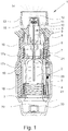
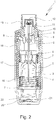
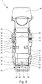
- Figs. 1 and 2 show a known nebulizer 1 for atomizing a fluid 2, particularly a highly effective pharmaceutical composition, medicament or the like, diagrammatically shown in a non-tensioned state ( Fig. 1 ) and in a tensioned state ( Fig. 2 ).
- the nebulizer 1 is constructed in particular as a portable inhaler and preferably operates only mechanical and/or without propellant gas.
- an aerosol 14 ( Fig. 1 ) is formed, which can be breathed in or inhaled by a user.
- the inhaling is done at least once a day, more particularly several times a day, preferably at set intervals, depending on the complain or illness from which a patient is suffering.
- the nebulizer 1 is provided with or comprises an insertable or replaceable container 3 containing the fluid 2.
- the container 3 thus forms a reservoir for the fluid 2, which is to be nebulized.
- the container 3 contains multiple doses of fluid 2 or active substance in particular sufficient to provide up to 200 dosage units or doses, for example, i.e. to allow up to 200 sprays or applications.
- a typical container 3, as disclosed in WO 96/06011 A1 holds e.g. a volume of about 2 to 20 ml.
- the dose can vary, in particular depending on the fluid 2 or medicament.
- the nebulizer 1 can be adapted respectively.
- the number of doses contained in the container 3 and/or the total volume of the fluid 2 contained in the container 3 can vary depending on the fluid 2 or respective medicament and/or depending on the container 3 and/or depending on the necessary medication or the like.
- the container 3 can be replaced or exchanged, wherein the number of containers 3, which can be used with the same nebulizer 1, is preferably restricted , e.g. to a total number of four or five containers 3.
- the container 3 is preferably substantially cylindrical or cartridge-shaped and once the nebulizer 1 has been opened the container 3 can be inserted therein preferably from below and changed if desired. It is preferably of rigid construction, the fluid 2 in particular being held in a collapsible bag 4 in the container 3.
- the nebulizer 1 comprises preferably a pressure generator 5 for conveying and nebulizing the fluid 2, particularly in a preset and optionally in an adjustable dosage amount.
- the pressure generator 5 comprises preferably a holder 6 for releasable holding the container 3, a drive spring 7 associated to the holder 6, only partly shown, a blocking element 8 which can catch and block the holder 6 and can be manually operated to release the holder 6 allowing drive spring 7 to expand, a conveying element, such as a conveying tube 9, a non-return valve 10, a pressure chamber 11 and/or a nozzle 12 for nebulizing the fluid 2 into a mouthpiece 13.
- the completely inserted container 3 is fixed or held in the nebulizer 1 via the holder 6, in particular when or with completely closing the nebulizer 1 or housing part 18, such that the conveying tube 9 penetrates into the container 3.
- the holder 6 is preferably constructed so that the container 3 can be exchanged.
- the nebulizer 1 operates with a spring pressure of 5 to 200 MPa, preferably 10 to 100 MPa on the fluid 2, and/or with a volume of fluid 2 delivered per stroke of 10 to 50 ⁇ l, preferably 10 to 20 ⁇ l, most preferably about 15 ⁇ l.
- the fluid 2 is converted into or nebulized as aerosol 14, the droplets of which have an aerodynamic diameter of up to 20 ⁇ m, preferably 3 to 10 ⁇ m.
- the generated jet spray has an angle of 20° to 160°, preferably 80° to 100°.
- a user or patient can inhale the aerosol 14, preferably while an air supply can be sucked into the mouthpiece 13 through at least one optional air supply opening 15.
- the nebulizer 1 or drive spring 7 can be manually activated or tensioned, in particular by actuation of an actuation member.
- the nebulizer 1 comprises preferably an upper housing part 16 and an inner part 17 which is rotatable relative thereto ( Fig. 2 ) having an upper part 17a and a lower part 17b ( Fig. 1 ), while an in particular manually operable (lower) housing part 18 is releasable fixed, particularly fitted or held onto the inner part 17, preferably by means of a retaining element 19.
- the housing parts 16 and 18 form a housing of the nebulizer 1.
- the housing can be opened and/or the housing part 18 can be detached from the nebulizer 1 or its housing.
- the actuation member preferably the housing part 18, can be actuated, here rotated relative to the upper housing part 16, carrying with it or driving the inner part 17.
- the drive spring 7 is tensioned in the axial direction by means of a gear or transmission (not shown) formed between the inner part 17, in particular its upper part 17a, and the holder 6 and acting on the holder 6.
- the container 3 is moved axially downwards until the container 3 assumes an end position as shown in Fig. 2 .
- the drive spring 7 is under tension and can be caught or held by the blocking member 8.
- the container 3 is moved back into its original position (non-tensioned position or state shown in Fig. 1 ) by the drive spring 7.
- the container 3 executes a lifting or stroke or linear movement or a back and forth movement during the tensioning process or conveying of fluid 2 and/or during the pressure generation nebulization (process).
- the housing part 18 preferably forms a cap-like lower housing part and fits around or over a lower free end portion of the container 3.
- an aeration means such as an axially acting spring 20 arranged in the housing part 18, comes in contact with base 21 of the container 3 and pierces the container 3 or a base seal thereon with a piercing element 22 when the container 3 makes contact with it for the first time, to allow air in or aeration.
- the nebulizer 1 comprises preferably a counting device 23, which counts the actuations or operations (uses) of the nebulizer 1, preferably by detecting its tensioning or the rotation of the inner part 17 relative to the upper part 16 of the housing.
- the counting device 23 or a lock 24 preferably formed by a locking spring as shown in Fig. 1 and actuated by the counting device 23
- nebulizer 1 according to the present invention will be described in more detail with reference to the further Figures, wherein only essential differences from the nebulizer 1 described above will be emphasized or described.
- the remarks relating to Figs. 1 and 2 apply preferably accordingly or in a similar manner, while any desired combinations of features are possible.
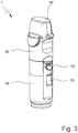
- Fig. 3 shows the nebulizer 1 in a perspective side view with mounted (lower) housing part 18.
- the nebulizer 1, the housing part 18 or counting device 23 comprises a display 25 which is visible from the outside.
- the display 25 is preferably held by or integrated into the housing part 18.
- other constructional solutions are possible as well.
- the counting device 23 and/or lock 24 are arranged - at least essentially - at or within the housing part 18.
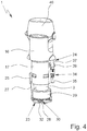
- Fig. 4 shows the nebulizer 1 in another perspective side view with cut-away housing part 18 so that the counting device 23, the lock 24 and the display 25 are visible.
- the counting device 23 and the display 25 work electronically.
- the display 25 is connected with the counting device 23, more particularly with a circuit board 26 of the counting device 23, via a cable 27 as indicated in Fig. 4 .
- the counting device 23 or circuit board 26 controls the display 25, in particular for showing or displaying information, such as a number of operations that have been performed or still can be performed with the current container 3, a number of containers 3 that have been or still can be used with or inserted into the nebulizer 1, information relating to the nebulizer 1 or fluid 2, e.g. about a blocking or locking state of the nebulizer 1, and/or instructions for handling the nebulizer 1, e.g. for replacing the container 3, or the like.
- the shown information can change if desired.
- the display 25 can be used to control the counting device 23.
- the display 25 is preferably formed by a touch screen.
- the counting device 23 or circuit board 26 is located at or adjacent to a bottom or axial end of the housing part 18 and/or clippsed into the housing part 18, as schematically shown in the schematic section of the nebulizer 1 according to Fig. 5 .
- the container 3 is provided with an electronic storage 28 as indicated in the schematic section of Fig. 5 .
- the electronic storage is electrically erasable, programmable and/or for read-only.
- the electronic storage 28 is formed by or comprises a so-called EEPROM.
- the electronic storage 28 is associated to and preferably rigidly connected to the container 3 and/or is inseparable from the container 3.
- the electronic storage 28 is mounted at or to the container 3 by means of a holding element 29.
- the holding element 29 is ring-like and/or encompasses one end and/or the base 21 of the container 3.
- the holding element 29 is connected with the container 3 via a form-fit and/or encompasses a lower edge of the container 3.
- the holding element 29 is inseparably or rigidly fixed to the container 3 and/or moves together with the container 3.
- the holding element 29 is made of plastics and/or molded, in particular directly on the container 3.
- the storage 28 and/or holding element 29 can be attached to the container 3 alternatively or additionally in any other suitable manner, e.g. by gluing, clamping or the like.
- Holding element 29 may form a grip for holding the container 3 and/or for pulling the container 3, in particular for detaching the container 3 or pulling the container 3 out of the inner part 17.
- the container 3 comprises connecting means 30 (shown only schematically in Fig. 5 ) for electrically connecting the electronic storage 28, in particular with the counting device 23 or its circuit board 26.
- the electronic storage 28, the holding element 29 and/or the connecting means 30 are located at or adjacent to axial end or base 21 of the container 3.
- the connecting means 30 is adapted to allow a respective movement of the electronic storage 28 associated to the container 3 relative to the counting device 23 or its circuit board 26 associated to the housing of the nebulizer 1, in particular the housing part 18.
- the connecting means 30 is adapted to provide the electrical connection to the electronic storage 28 at only in an end position, in particular the lower position or the position with tensioned drive spring 7, of the container 3. This allows a simple construction.
- the connecting means 30 comprises multiple conductors 31 arranged ring-like and coaxially on the lower end face of the container 3 as shown in the perspective view of the separate container 3 according to Fig. 6 .
- the conductors 31 are arranged in a common plane and/or offset axially against a lower or free edge of the holding element 29.
- the holding element 29 comprises or is provided with a central or through hole 33 so that the piercing element 22, which is preferably held by the counting device 23 or circuit board 26, can extend through the holding element 29 to pierce or vent the container 3 when moved into its lower position as shown in Fig. 5 .
- the conductors 31 are arranged coaxially around this hole 33.
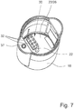
- Fig. 7 shows a perspective view of the separated housing part 18 from above.
- the piercing element 22, the circuit board 26 and an arrangement of wipers 32 are visible in the housing part 18, in particular on the bottom in the housing part 18.
- pairs of wipers 32 are provided to ensure a secure electrical contact to one associated conductor 31.
- the wipers 32 are biased upwards and/or against the container 3 or conductors 31. This secures good electrical contact (at least when the container 3 is in its lower position and/or in the tensioned position).
- the wipers 32 are preferably supported by and/or electrically connected to or with the connecting device 23 or circuit board 26.
- the conductors 31 are electrically connected to the electronic storage 28.
- the conductors 31 and wipers 32 allow an electric connection of the electronic storage 28 with the counting device 23 or circuit board 26 or vice versa, at least when the container 3 is in its lower position.
- the counting device 23 or its circuit board 26 is clippsed into the housing part 18.
- the circuit board 26 can be connected to or within the housing part 18 in any other suitable manner as well.
- the nebulizer 1 comprises an electric drive 34 actuating the lock 24.
- the electric drive 34 is schematically shown in Fig. 4 .
- the electric drive 34 comprises preferably an electric motor 35 and an associated (threaded) spindle 36 as schematically indicated in Fig. 5 .
- the lock 34 comprises preferably a locking element 37 for engaging into a locking recess 38 in a locked state.
- Fig. 5 shows the locking element 37 in a non-engaging state.
- the locking element 37 is preferably (linearly) moveable between the position engaging into the respective locking recess 38 and the non-engaging position and vice versa, in particular by means of the electric drive 34.
- the locking element 37 meshes with the spindle 36 so that the locking element 37 can be moved (axially) by the respective turning of the spindle 36 by means of the motor 35.
- the locking element 37 is preferably provided with a non-circular outer contour or cross section or with a radial protrusion 39 that is guided in an axial groove 40 or the like so that the locking element 37 can move axially or linearly, but is prevented from turning together with the spindle 36.
- a non-circular outer contour or cross section or with a radial protrusion 39 that is guided in an axial groove 40 or the like so that the locking element 37 can move axially or linearly, but is prevented from turning together with the spindle 36.
- other constructional solutions are possible as well.
- the nebulizer 1 or upper housing part 16 comprises multiple, here two recesses 38 to allow blocking of the nebulizer 1 or lower housing part 18 in different rotational positions, in particular in two positions, preferably offset by 180°, as the housing part 18 can be rotated preferably in 180° steps for tensioning the drive spring 7 and/or conveying the fluid 2 into the pressure chamber 11.
- the lock 24 or locking element 37 can lock the nebulizer 1 in a locked state, preferably against using the nebulizer 1, in particular against tensioning the drive spring 7 and/or turning the housing part 18 and/or against actuating or pushing the blocking element 8.
- the lock 24 or locking element 37 can block turning of the (lower) housing part 18 and, thus, of the inner part 17 relative to the upper housing part 16.
- the lock 24 or locking element 37 is arranged or located or guided at the housing part 18 and engages into the upper housing part 16 of the nebulizer 1 or in the recess 38 (which is preferably formed in the upper housing part 16) in a locked state or vice versa.
- the lock 24 is preferably operated or actuated electrically. With other words, the lock 24 works preferably electrically, here by means of the electric drive 34.
- the counting device 23 controls the lock 24, in particular the electric drive 34.
- the electric drive 34 is connected to the counting device 23 or its circuit board 26 by a cable 41 as schematically indicated in Fig. 5 .
- the nebulizer 1 or counting device 23 comprises preferably a battery 42 for power supply.
- This battery 42 may be rechargeable or replaceable, if desired.
- the nebulizer 1 or counting device 23 may comprise an integrated circuit, storage and/or microprocessor 43 as schematically indicated in Fig. 5 .
- relevant components such as the battery 42 and/or the integrated circuit, storage and/or microprocessor 43, any connectors for the cables 27 and 41 or the like, are connected with and/or held by the circuit board 26.
- the nebulizer 1 can be blocked against opening or container replacement, in particular against the removing or detaching the lower housing part 18. This is called “opening blocking” in the following.
- the opening blocking is preferably controlled by the lock 24, the locking element 37 and/or the electric drive 34.
- the retaining element 19, which has to be depressed - in particular against a force of a spring 44 - for detaching the housing part 18 from the nebulizer 1 or inner part 17, can be blocked by the lock 24 or locking element 37 against depressing.
- the retaining element 19 or an associated portion may extend around the inner part 17 adjacent to the locking element 37 and, for example, may comprise a counter surface or stop 45 that can abut at the locking element 37 or can be blocked by the locking element 37 so that depressing and/or radial displacement of the retaining element 19 can be prevented as shown in Fig. 5 depending on the position of the locking element 37 for realizing the opening blocking.
- other constructional solutions are possible as well, such as axial displacement of retaining element 19.
- the electronic storage 28 can be read, in particular by the device 23 via the connecting means 30.
- information stored in the electronic storage 28 can be considered, processed and/or displayed, in particular via display 25.
- the information can include information about the fluid 2 contained in the container 3, filling date, any previous use(s) of the container 3 or the like. For example, when the container 3 has already been used, it is possible that its first or last use has been stored in the electronic storage 28 and can prevent further use with the present, the same and/or another nebulizer 1.
- the display 25 is used to guide a user or patient (not shown).
- respective instructions can be displayed, in particular when the nebulizer 1 has to be used or primed multiple times before using the first, when the container 3 has to be replaced and/or when the nebulizer 1 has been finally locked or blocked against any further use.
- the display 25 can display the number of uses or operations of the nebulizer 1 that have been performed or still can be performed with the current container 3 or with all containers 3, and/or the number of containers 3 that have been used or inserted or can still be used or inserted.
- the counting device 23 counts or detects uses or operations of nebulizer 1, in particular by detecting or counting tensioning of the nebulizer 1 or its drive spring 7, rotation of housing part 18 or inner part relative to the upper housing part 16, fluid conveying, fluid atomization, pressure generation, actuation of the locking element 8, any other actuation, movement of the container 3, and/or the like.
- the counting device 23 detects or counts movement of the container 3, in particular the stroke of the container 3 when tensioning the drive spring 7 and/or during fluid conveying or sucking from the container 3.
- the counting device 23 detects or counts preferably each time when the container 3 reaches its lower position or the tensioned position. Preferably, this is detected or counted by means of the connecting 30 or wipers 32 and/or by means of a micro switch, proximity switch or the like.
- the nebulizer 3 reaches the tensioned position, one or more conductors 31 are electrically connected with one or more wipers 32 so that a closed electrical loop and/or an electrical connection to the electronic storage 28 can be established and detected and, accordingly, counted as a use or operation of the nebulizer 1.
- other kinds of detection and counting are possible additionally or alternatively.
- each use or operation of the nebulizer 1 or container 3 can be stored in the electronic storage 28.
- additional data such as date, time, first use, last use and/or the like in the electronic storage 28 and/or in the counting device 23.
- the counting device 23 may comprise a respective time base or the like.
- the nebulizer 1 When a predetermined number of operations has been used or exceeded, i.e. when a predetermined number of doses of fluid 2 or more has been discharged, the nebulizer 1 enters the first locked state in which the nebulizer 1 is locked against further use with the current container 3. This locking is achieved by the lock 24 by locking the housing part 18 against any further rotation and/or by engaging the locking element 37 into the respective locking recess 38. In the first locked state, the locking element 37 is moved in a position such that it locks the nebulizer 1 against further use or tensioning, but deactivates the opening blocking.
- the locking element 37 may be moved axially so far into the recess 38 that the stop 45 can pass or can move into a depression of the locking element 37 or the like so that the retaining element 19 can be depressed to open the nebulizer 1 and replace the container 3.
- the container 3 It is possible to replace the container 3 together with the housing part 18 and the counting device 23. However, preferably the container 3 is replaced and the same housing part 18 and counting device 23 are used again, wherein the new container 3 is preferably inserted into the housing 18 in a first step and, then, the housing part 18 is reconnected to the nebulizer 1.
- the counting device 23 detects replacement of the container 3, in particular by establishing an electric contact (which could also be used for counting the containers 3 and uses of the nebulizer 1), e.g. electrically connecting the electronic storage 28 of the new container 3 and/or in any other suitable manner, e.g. by means of a micro switch or the like.
- the lock 24 is unlocked or deactivated and the opening blocking is activated again, in particular by returning the locking element 37 into its non-engaging position by means of the electric drive 34.
- the nebulizer 1 can be used with the new container 3 as already described.
- the nebulizer 1 is preferably provided with a so-called life span blocking. This means that the nebulizer 1 cannot be used anymore and, in particular, any further container replacement is not further possible.
- This finally blocked state is called second locked state in the present invention. The second locked state is entered when a predetermined number of containers 3 have been inserted and used in the nebulizer 1.
- the lock 24 or locking element 37 locks the nebulizer 1 against further use, but does not deactivate opening blocking.
- This can be achieved e.g. in that the locking element 37 is moved not so far into recess 38 such that the stop 45 cannot pass and the retaining element 19 cannot be depressed so that opening of the nebulizer 1 and container replacement are not possible.
- the lock 24 and/or first locked state can be reset if the container 3 is or has been replaced. However, the lock 24 and/or first locked state are blocked against resetting in the second locked state. It has to be noted that Fig.
- FIG. 3 to 5 show the nebulizer 1 with a cover 46 covering the mouth piece 13. This cover 46 can be removed or opened for using the nebulizer 1.
- individual features, aspects and/or principles of the embodiment described may also be combined with one another if desired and may be used particularly in the nebulizer according to Figs. 1 and 2 but also in similar or different nebulizers.
- the proposed nebulizer 1 is preferably designed to be portable and in particular is a mobile hand operated device.
- the proposed solution may, however, be used not only in the nebulizers 1 specifically described here but also in other nebulizers or inhalers, e.g. powder inhalers or so-called metered dose inhalers.
- the fluid 2 is a liquid, as already mentioned, especially an aqueous pharmaceutical formulation or an ethanolic pharmaceutical formulation. However, it may also be some other pharmaceutical formulation, a suspension or the like.
- the fluid 2 may also comprise particles or powder.
- the expulsion nozzle 12 instead of the expulsion nozzle 12, some other kind of supply device may be provided, especially an expulsion opening (not shown) or a supply channel (not shown) for supplying the fluid or powder or the like into the mouthpiece 13.
- the optional air supply opening 15 then serves to supply ambient air preferably in parallel so as to general or allow an airflow with a sufficient volume for breathing in or inhaling through the mouthpiece 13.
- the fluid 2 may also be atomized by means of a propellant gas.
- Preferred ingredients and/or formulations of the preferably medicinal fluid 2 are listed in particular in WO 2009/115200 A1 , preferably pages 25 to 40. In particular, these may be aqueous or non-aqueous solutions, mixtures, formulations containing ethanol or free from solvent, or the like.
Landscapes
- Health & Medical Sciences (AREA)
- Engineering & Computer Science (AREA)
- Life Sciences & Earth Sciences (AREA)
- Anesthesiology (AREA)
- General Health & Medical Sciences (AREA)
- Biomedical Technology (AREA)
- Heart & Thoracic Surgery (AREA)
- Hematology (AREA)
- Veterinary Medicine (AREA)
- Animal Behavior & Ethology (AREA)
- Public Health (AREA)
- Pulmonology (AREA)
- Bioinformatics & Cheminformatics (AREA)
- Biophysics (AREA)
- Mechanical Engineering (AREA)
- Containers And Packaging Bodies Having A Special Means To Remove Contents (AREA)
- Infusion, Injection, And Reservoir Apparatuses (AREA)
Priority Applications (1)
| Application Number | Priority Date | Filing Date | Title |
|---|---|---|---|
| EP12722389.9A EP2714280B1 (en) | 2011-05-23 | 2012-05-22 | Nebulizer |
Applications Claiming Priority (3)
| Application Number | Priority Date | Filing Date | Title |
|---|---|---|---|
| EP11004237 | 2011-05-23 | ||
| EP12722389.9A EP2714280B1 (en) | 2011-05-23 | 2012-05-22 | Nebulizer |
| PCT/EP2012/059454 WO2012160047A2 (en) | 2011-05-23 | 2012-05-22 | Nebulizer |
Publications (2)
| Publication Number | Publication Date |
|---|---|
| EP2714280A2 EP2714280A2 (en) | 2014-04-09 |
| EP2714280B1 true EP2714280B1 (en) | 2018-03-21 |
Family
ID=46146893
Family Applications (1)
| Application Number | Title | Priority Date | Filing Date |
|---|---|---|---|
| EP12722389.9A Active EP2714280B1 (en) | 2011-05-23 | 2012-05-22 | Nebulizer |
Country Status (4)
| Country | Link |
|---|---|
| US (1) | US10080853B2 (enExample) |
| EP (1) | EP2714280B1 (enExample) |
| JP (1) | JP6016311B2 (enExample) |
| WO (1) | WO2012160047A2 (enExample) |
Families Citing this family (29)
| Publication number | Priority date | Publication date | Assignee | Title |
|---|---|---|---|---|
| EP2077132A1 (en) | 2008-01-02 | 2009-07-08 | Boehringer Ingelheim Pharma GmbH & Co. KG | Dispensing device, storage device and method for dispensing a formulation |
| US10011906B2 (en) | 2009-03-31 | 2018-07-03 | Beohringer Ingelheim International Gmbh | Method for coating a surface of a component |
| US9265910B2 (en) | 2009-05-18 | 2016-02-23 | Boehringer Ingelheim International Gmbh | Adapter, inhalation device, and nebulizer |
| US10016568B2 (en) | 2009-11-25 | 2018-07-10 | Boehringer Ingelheim International Gmbh | Nebulizer |
| AP3141A (en) | 2009-11-25 | 2015-02-28 | Boehringer Ingelheim Int | Nebulizer |
| WO2011064163A1 (en) | 2009-11-25 | 2011-06-03 | Boehringer Ingelheim International Gmbh | Nebulizer |
| US9943654B2 (en) | 2010-06-24 | 2018-04-17 | Boehringer Ingelheim International Gmbh | Nebulizer |
| WO2012130757A1 (de) | 2011-04-01 | 2012-10-04 | Boehringer Ingelheim International Gmbh | Medizinisches gerät mit behälter |
| US9827384B2 (en) | 2011-05-23 | 2017-11-28 | Boehringer Ingelheim International Gmbh | Nebulizer |
| WO2013152894A1 (de) | 2012-04-13 | 2013-10-17 | Boehringer Ingelheim International Gmbh | Zerstäuber mit kodiermitteln |
| US20140216444A1 (en) * | 2013-02-06 | 2014-08-07 | Flextronics Ap, Llc | Metered dose inhaler with an electronic dose counter |
| JP6643231B2 (ja) | 2013-08-09 | 2020-02-12 | ベーリンガー インゲルハイム インターナショナル ゲゼルシャフト ミット ベシュレンクテル ハフツング | ネブライザ |
| EP2835146B1 (en) * | 2013-08-09 | 2020-09-30 | Boehringer Ingelheim International GmbH | Nebulizer |
| CN106456913B (zh) * | 2014-05-07 | 2019-08-30 | 勃林格殷格翰国际有限公司 | 喷雾器和容器 |
| EP3139984B1 (en) | 2014-05-07 | 2021-04-28 | Boehringer Ingelheim International GmbH | Nebulizer |
| DK3139979T3 (da) | 2014-05-07 | 2023-10-09 | Boehringer Ingelheim Int | Enhed, forstøver og fremgangsmåde |
| BR112017003868A2 (pt) | 2014-08-28 | 2018-06-26 | Microdose Therapeutx, Inc. | módulo de monitoração de conformidade para inaladores acionados pela respiração, inaladores que o contenham, método de utilização e programa de computador para execução do método. |
| TW201636068A (zh) * | 2015-01-13 | 2016-10-16 | 賽諾菲股份有限公司 | 藥物輸送裝置之組件 |
| JP6472326B2 (ja) * | 2015-05-22 | 2019-02-20 | アトムメディカル株式会社 | 呼吸用気体の加温加湿器 |
| JP6900372B2 (ja) | 2015-11-09 | 2021-07-07 | ベーリンガー インゲルハイム インターナショナル ゲゼルシャフト ミット ベシュレンクテル ハフツング | ネブライザ及び容器 |
| CN118085011A (zh) | 2016-08-17 | 2024-05-28 | 勃林格殷格翰国际公司 | 制备含有生物分子的高度浓缩的液体制剂的方法 |
| US11224556B2 (en) * | 2017-04-14 | 2022-01-18 | Manan Shukla | Inhaler compliance device and monitoring system |
| US11229754B2 (en) * | 2017-07-21 | 2022-01-25 | Boehringer Ingelheim International Gmbh | Nebulizer and reservoir |
| AU2018303702B2 (en) * | 2017-07-21 | 2023-09-21 | Boehringer Ingelheim International Gmbh | Nebulizer |
| USD929565S1 (en) * | 2018-07-13 | 2021-08-31 | Laboratorios Liconsa, S.A. | Inhaler |
| KR102588714B1 (ko) * | 2018-09-27 | 2023-10-16 | 에스에이치엘 메디컬 아게 | 에어로졸 디스펜서용 잠금 메커니즘 |
| US20230321365A1 (en) * | 2020-06-30 | 2023-10-12 | Microbase Technology Corp. | Sprayer and storage device |
| USD979742S1 (en) * | 2021-03-24 | 2023-02-28 | Merxin Ltd | Inhaler |
| WO2024209254A1 (en) * | 2023-04-06 | 2024-10-10 | Neutec Inhaler Ilac Sanayi Ve Ticaret Anonim Sirketi | Nebulizer for a fluid contained in a container |
Citations (3)
| Publication number | Priority date | Publication date | Assignee | Title |
|---|---|---|---|---|
| US4934358A (en) * | 1986-03-24 | 1990-06-19 | Sven-Erik Nilsson | Device for self-administration of physiologically active substances, with prevention of overdosing |
| US5284133A (en) * | 1992-07-23 | 1994-02-08 | Armstrong Pharmaceuticals, Inc. | Inhalation device with a dose-timer, an actuator mechanism, and patient compliance monitoring means |
| US20110011393A1 (en) * | 2005-08-24 | 2011-01-20 | Boehringer Ingelheim International Gmbh | Atomizer |
Family Cites Families (12)
| Publication number | Priority date | Publication date | Assignee | Title |
|---|---|---|---|---|
| US5469750A (en) * | 1991-03-05 | 1995-11-28 | Aradigm Corporation | Method and apparatus for sensing flow in two directions and automatic calibration thereof |
| WO1992017231A1 (en) | 1991-03-28 | 1992-10-15 | Innomed, Inc. | Microelectronic inhaler having a counter and timer |
| DE4428434A1 (de) | 1994-08-11 | 1996-02-15 | Boehringer Ingelheim Kg | Verschlußkappe und Verfahren zur gasblasenfreien Füllung von Behältern |
| CA2176047C (en) * | 1995-05-22 | 2000-04-11 | Mohi Sobhani | Spring loaded rotary connector |
| US6331117B1 (en) * | 1998-06-05 | 2001-12-18 | Gary L. Brundage | Electrical component system with rotatable electrical contacts |
| AU3471799A (en) | 1998-07-06 | 2000-01-24 | Iep Group, Inc. | Counter for fluid dispenser |
| US20020000225A1 (en) * | 2000-06-02 | 2002-01-03 | Carlos Schuler | Lockout mechanism for aerosol drug delivery devices |
| EP1301230A1 (en) * | 2000-07-15 | 2003-04-16 | Glaxo Group Limited | Medicament dispenser |
| US6435175B1 (en) | 2000-08-29 | 2002-08-20 | Sensormedics Corporation | Pulmonary drug delivery device |
| EP1599243B1 (en) * | 2003-03-04 | 2013-12-25 | Norton Healthcare Limited | Medicament dispensing device with a display indicative of the state of an internal medicament reservoir |
| DE102004009435A1 (de) * | 2004-02-24 | 2005-12-08 | Boehringer Ingelheim International Gmbh | Zerstäuber |
| WO2009115200A1 (en) | 2008-03-17 | 2009-09-24 | Boehringer Ingelheim International Gmbh | Reservoir and nebulizer |
-
2012
- 2012-05-21 US US13/476,217 patent/US10080853B2/en active Active
- 2012-05-22 WO PCT/EP2012/059454 patent/WO2012160047A2/en not_active Ceased
- 2012-05-22 EP EP12722389.9A patent/EP2714280B1/en active Active
- 2012-05-22 JP JP2014511840A patent/JP6016311B2/ja active Active
Patent Citations (3)
| Publication number | Priority date | Publication date | Assignee | Title |
|---|---|---|---|---|
| US4934358A (en) * | 1986-03-24 | 1990-06-19 | Sven-Erik Nilsson | Device for self-administration of physiologically active substances, with prevention of overdosing |
| US5284133A (en) * | 1992-07-23 | 1994-02-08 | Armstrong Pharmaceuticals, Inc. | Inhalation device with a dose-timer, an actuator mechanism, and patient compliance monitoring means |
| US20110011393A1 (en) * | 2005-08-24 | 2011-01-20 | Boehringer Ingelheim International Gmbh | Atomizer |
Also Published As
| Publication number | Publication date |
|---|---|
| WO2012160047A3 (en) | 2013-03-07 |
| US10080853B2 (en) | 2018-09-25 |
| JP6016311B2 (ja) | 2016-10-26 |
| WO2012160047A2 (en) | 2012-11-29 |
| JP2014516698A (ja) | 2014-07-17 |
| US20130125880A1 (en) | 2013-05-23 |
| EP2714280A2 (en) | 2014-04-09 |
Similar Documents
| Publication | Publication Date | Title |
|---|---|---|
| EP2714280B1 (en) | Nebulizer | |
| EP2504052B1 (en) | Nebulizer | |
| KR102730574B1 (ko) | 분무기, 표시 디바이스 및 컨테이너 | |
| US11786676B2 (en) | Methods and systems for supplying aerosolization devices with liquid medicaments | |
| EP2504050B1 (en) | Nebulizer | |
| EP2714279B1 (en) | Nebulizer | |
| JP2019115673A (ja) | ネブライザ | |
| EP3374011B1 (en) | System comprising nebulizer and container | |
| US20230277783A1 (en) | Nebulizer | |
| WO2007022898A2 (en) | Atomiser comprising a counter and an end of operation lock | |
| AU2015202524A1 (en) | Nebulizer | |
| HK40071991A (en) | Nebulizer, indicator device and container | |
| HK1230532B (en) | Nebulizer |
Legal Events
| Date | Code | Title | Description |
|---|---|---|---|
| PUAI | Public reference made under article 153(3) epc to a published international application that has entered the european phase |
Free format text: ORIGINAL CODE: 0009012 |
|
| 17P | Request for examination filed |
Effective date: 20130920 |
|
| AK | Designated contracting states |
Kind code of ref document: A2 Designated state(s): AL AT BE BG CH CY CZ DE DK EE ES FI FR GB GR HR HU IE IS IT LI LT LU LV MC MK MT NL NO PL PT RO RS SE SI SK SM TR |
|
| AX | Request for extension of the european patent |
Extension state: BA ME |
|
| 17Q | First examination report despatched |
Effective date: 20160531 |
|
| GRAP | Despatch of communication of intention to grant a patent |
Free format text: ORIGINAL CODE: EPIDOSNIGR1 |
|
| INTG | Intention to grant announced |
Effective date: 20171020 |
|
| RIN1 | Information on inventor provided before grant (corrected) |
Inventor name: HENDERSON, CHARLES Inventor name: ROHRSCHNEIDER, MARC Inventor name: DEANE, KEVIN, PETER Inventor name: JENNINGS, DOUGLAS, IVAN Inventor name: HOLAKOVSKY, HOLGER Inventor name: WITTE, FLORIAN |
|
| GRAS | Grant fee paid |
Free format text: ORIGINAL CODE: EPIDOSNIGR3 |
|
| GRAA | (expected) grant |
Free format text: ORIGINAL CODE: 0009210 |
|
| AK | Designated contracting states |
Kind code of ref document: B1 Designated state(s): AL AT BE BG CH CY CZ DE DK EE ES FI FR GB GR HR HU IE IS IT LI LT LU LV MC MK MT NL NO PL PT RO RS SE SI SK SM TR |
|
| AX | Request for extension of the european patent |
Extension state: BA ME |
|
| REG | Reference to a national code |
Ref country code: GB Ref legal event code: FG4D |
|
| REG | Reference to a national code |
Ref country code: CH Ref legal event code: EP |
|
| REG | Reference to a national code |
Ref country code: AT Ref legal event code: REF Ref document number: 980535 Country of ref document: AT Kind code of ref document: T Effective date: 20180415 |
|
| REG | Reference to a national code |
Ref country code: IE Ref legal event code: FG4D |
|
| REG | Reference to a national code |
Ref country code: DE Ref legal event code: R096 Ref document number: 602012044177 Country of ref document: DE |
|
| REG | Reference to a national code |
Ref country code: FR Ref legal event code: PLFP Year of fee payment: 7 |
|
| REG | Reference to a national code |
Ref country code: NL Ref legal event code: MP Effective date: 20180321 |
|
| PG25 | Lapsed in a contracting state [announced via postgrant information from national office to epo] |
Ref country code: NO Free format text: LAPSE BECAUSE OF FAILURE TO SUBMIT A TRANSLATION OF THE DESCRIPTION OR TO PAY THE FEE WITHIN THE PRESCRIBED TIME-LIMIT Effective date: 20180621 Ref country code: CY Free format text: LAPSE BECAUSE OF FAILURE TO SUBMIT A TRANSLATION OF THE DESCRIPTION OR TO PAY THE FEE WITHIN THE PRESCRIBED TIME-LIMIT Effective date: 20180321 Ref country code: LT Free format text: LAPSE BECAUSE OF FAILURE TO SUBMIT A TRANSLATION OF THE DESCRIPTION OR TO PAY THE FEE WITHIN THE PRESCRIBED TIME-LIMIT Effective date: 20180321 Ref country code: HR Free format text: LAPSE BECAUSE OF FAILURE TO SUBMIT A TRANSLATION OF THE DESCRIPTION OR TO PAY THE FEE WITHIN THE PRESCRIBED TIME-LIMIT Effective date: 20180321 Ref country code: FI Free format text: LAPSE BECAUSE OF FAILURE TO SUBMIT A TRANSLATION OF THE DESCRIPTION OR TO PAY THE FEE WITHIN THE PRESCRIBED TIME-LIMIT Effective date: 20180321 |
|
| REG | Reference to a national code |
Ref country code: LT Ref legal event code: MG4D |
|
| REG | Reference to a national code |
Ref country code: AT Ref legal event code: MK05 Ref document number: 980535 Country of ref document: AT Kind code of ref document: T Effective date: 20180321 |
|
| PG25 | Lapsed in a contracting state [announced via postgrant information from national office to epo] |
Ref country code: BG Free format text: LAPSE BECAUSE OF FAILURE TO SUBMIT A TRANSLATION OF THE DESCRIPTION OR TO PAY THE FEE WITHIN THE PRESCRIBED TIME-LIMIT Effective date: 20180621 Ref country code: GR Free format text: LAPSE BECAUSE OF FAILURE TO SUBMIT A TRANSLATION OF THE DESCRIPTION OR TO PAY THE FEE WITHIN THE PRESCRIBED TIME-LIMIT Effective date: 20180622 Ref country code: LV Free format text: LAPSE BECAUSE OF FAILURE TO SUBMIT A TRANSLATION OF THE DESCRIPTION OR TO PAY THE FEE WITHIN THE PRESCRIBED TIME-LIMIT Effective date: 20180321 Ref country code: SE Free format text: LAPSE BECAUSE OF FAILURE TO SUBMIT A TRANSLATION OF THE DESCRIPTION OR TO PAY THE FEE WITHIN THE PRESCRIBED TIME-LIMIT Effective date: 20180321 Ref country code: RS Free format text: LAPSE BECAUSE OF FAILURE TO SUBMIT A TRANSLATION OF THE DESCRIPTION OR TO PAY THE FEE WITHIN THE PRESCRIBED TIME-LIMIT Effective date: 20180321 |
|
| PG25 | Lapsed in a contracting state [announced via postgrant information from national office to epo] |
Ref country code: RO Free format text: LAPSE BECAUSE OF FAILURE TO SUBMIT A TRANSLATION OF THE DESCRIPTION OR TO PAY THE FEE WITHIN THE PRESCRIBED TIME-LIMIT Effective date: 20180321 Ref country code: EE Free format text: LAPSE BECAUSE OF FAILURE TO SUBMIT A TRANSLATION OF THE DESCRIPTION OR TO PAY THE FEE WITHIN THE PRESCRIBED TIME-LIMIT Effective date: 20180321 Ref country code: IT Free format text: LAPSE BECAUSE OF FAILURE TO SUBMIT A TRANSLATION OF THE DESCRIPTION OR TO PAY THE FEE WITHIN THE PRESCRIBED TIME-LIMIT Effective date: 20180321 Ref country code: ES Free format text: LAPSE BECAUSE OF FAILURE TO SUBMIT A TRANSLATION OF THE DESCRIPTION OR TO PAY THE FEE WITHIN THE PRESCRIBED TIME-LIMIT Effective date: 20180321 Ref country code: AL Free format text: LAPSE BECAUSE OF FAILURE TO SUBMIT A TRANSLATION OF THE DESCRIPTION OR TO PAY THE FEE WITHIN THE PRESCRIBED TIME-LIMIT Effective date: 20180321 Ref country code: NL Free format text: LAPSE BECAUSE OF FAILURE TO SUBMIT A TRANSLATION OF THE DESCRIPTION OR TO PAY THE FEE WITHIN THE PRESCRIBED TIME-LIMIT Effective date: 20180321 Ref country code: PL Free format text: LAPSE BECAUSE OF FAILURE TO SUBMIT A TRANSLATION OF THE DESCRIPTION OR TO PAY THE FEE WITHIN THE PRESCRIBED TIME-LIMIT Effective date: 20180321 |
|
| PG25 | Lapsed in a contracting state [announced via postgrant information from national office to epo] |
Ref country code: AT Free format text: LAPSE BECAUSE OF FAILURE TO SUBMIT A TRANSLATION OF THE DESCRIPTION OR TO PAY THE FEE WITHIN THE PRESCRIBED TIME-LIMIT Effective date: 20180321 Ref country code: SK Free format text: LAPSE BECAUSE OF FAILURE TO SUBMIT A TRANSLATION OF THE DESCRIPTION OR TO PAY THE FEE WITHIN THE PRESCRIBED TIME-LIMIT Effective date: 20180321 Ref country code: CZ Free format text: LAPSE BECAUSE OF FAILURE TO SUBMIT A TRANSLATION OF THE DESCRIPTION OR TO PAY THE FEE WITHIN THE PRESCRIBED TIME-LIMIT Effective date: 20180321 Ref country code: SM Free format text: LAPSE BECAUSE OF FAILURE TO SUBMIT A TRANSLATION OF THE DESCRIPTION OR TO PAY THE FEE WITHIN THE PRESCRIBED TIME-LIMIT Effective date: 20180321 |
|
| REG | Reference to a national code |
Ref country code: CH Ref legal event code: PL |
|
| PG25 | Lapsed in a contracting state [announced via postgrant information from national office to epo] |
Ref country code: PT Free format text: LAPSE BECAUSE OF FAILURE TO SUBMIT A TRANSLATION OF THE DESCRIPTION OR TO PAY THE FEE WITHIN THE PRESCRIBED TIME-LIMIT Effective date: 20180723 |
|
| REG | Reference to a national code |
Ref country code: DE Ref legal event code: R097 Ref document number: 602012044177 Country of ref document: DE |
|
| PLBE | No opposition filed within time limit |
Free format text: ORIGINAL CODE: 0009261 |
|
| STAA | Information on the status of an ep patent application or granted ep patent |
Free format text: STATUS: NO OPPOSITION FILED WITHIN TIME LIMIT |
|
| REG | Reference to a national code |
Ref country code: BE Ref legal event code: MM Effective date: 20180531 |
|
| PG25 | Lapsed in a contracting state [announced via postgrant information from national office to epo] |
Ref country code: DK Free format text: LAPSE BECAUSE OF FAILURE TO SUBMIT A TRANSLATION OF THE DESCRIPTION OR TO PAY THE FEE WITHIN THE PRESCRIBED TIME-LIMIT Effective date: 20180321 Ref country code: MC Free format text: LAPSE BECAUSE OF FAILURE TO SUBMIT A TRANSLATION OF THE DESCRIPTION OR TO PAY THE FEE WITHIN THE PRESCRIBED TIME-LIMIT Effective date: 20180321 |
|
| REG | Reference to a national code |
Ref country code: IE Ref legal event code: MM4A |
|
| 26N | No opposition filed |
Effective date: 20190102 |
|
| PG25 | Lapsed in a contracting state [announced via postgrant information from national office to epo] |
Ref country code: CH Free format text: LAPSE BECAUSE OF NON-PAYMENT OF DUE FEES Effective date: 20180531 Ref country code: LI Free format text: LAPSE BECAUSE OF NON-PAYMENT OF DUE FEES Effective date: 20180531 |
|
| PG25 | Lapsed in a contracting state [announced via postgrant information from national office to epo] |
Ref country code: LU Free format text: LAPSE BECAUSE OF NON-PAYMENT OF DUE FEES Effective date: 20180522 |
|
| PG25 | Lapsed in a contracting state [announced via postgrant information from national office to epo] |
Ref country code: IE Free format text: LAPSE BECAUSE OF NON-PAYMENT OF DUE FEES Effective date: 20180522 |
|
| PG25 | Lapsed in a contracting state [announced via postgrant information from national office to epo] |
Ref country code: BE Free format text: LAPSE BECAUSE OF NON-PAYMENT OF DUE FEES Effective date: 20180531 Ref country code: SI Free format text: LAPSE BECAUSE OF FAILURE TO SUBMIT A TRANSLATION OF THE DESCRIPTION OR TO PAY THE FEE WITHIN THE PRESCRIBED TIME-LIMIT Effective date: 20180321 |
|
| PG25 | Lapsed in a contracting state [announced via postgrant information from national office to epo] |
Ref country code: MT Free format text: LAPSE BECAUSE OF NON-PAYMENT OF DUE FEES Effective date: 20180522 |
|
| PG25 | Lapsed in a contracting state [announced via postgrant information from national office to epo] |
Ref country code: TR Free format text: LAPSE BECAUSE OF FAILURE TO SUBMIT A TRANSLATION OF THE DESCRIPTION OR TO PAY THE FEE WITHIN THE PRESCRIBED TIME-LIMIT Effective date: 20180321 |
|
| PG25 | Lapsed in a contracting state [announced via postgrant information from national office to epo] |
Ref country code: HU Free format text: LAPSE BECAUSE OF FAILURE TO SUBMIT A TRANSLATION OF THE DESCRIPTION OR TO PAY THE FEE WITHIN THE PRESCRIBED TIME-LIMIT; INVALID AB INITIO Effective date: 20120522 |
|
| PG25 | Lapsed in a contracting state [announced via postgrant information from national office to epo] |
Ref country code: MK Free format text: LAPSE BECAUSE OF NON-PAYMENT OF DUE FEES Effective date: 20180321 |
|
| PG25 | Lapsed in a contracting state [announced via postgrant information from national office to epo] |
Ref country code: IS Free format text: LAPSE BECAUSE OF FAILURE TO SUBMIT A TRANSLATION OF THE DESCRIPTION OR TO PAY THE FEE WITHIN THE PRESCRIBED TIME-LIMIT Effective date: 20180721 |
|
| P01 | Opt-out of the competence of the unified patent court (upc) registered |
Effective date: 20230508 |
|
| PGFP | Annual fee paid to national office [announced via postgrant information from national office to epo] |
Ref country code: DE Payment date: 20250521 Year of fee payment: 14 |
|
| PGFP | Annual fee paid to national office [announced via postgrant information from national office to epo] |
Ref country code: GB Payment date: 20250521 Year of fee payment: 14 |
|
| PGFP | Annual fee paid to national office [announced via postgrant information from national office to epo] |
Ref country code: FR Payment date: 20250528 Year of fee payment: 14 |