EP2713637A2 - Location update method, device and system - Google Patents
Location update method, device and system Download PDFInfo
- Publication number
- EP2713637A2 EP2713637A2 EP11795214.3A EP11795214A EP2713637A2 EP 2713637 A2 EP2713637 A2 EP 2713637A2 EP 11795214 A EP11795214 A EP 11795214A EP 2713637 A2 EP2713637 A2 EP 2713637A2
- Authority
- EP
- European Patent Office
- Prior art keywords
- communication network
- mobile communication
- request message
- management device
- mobile
- Prior art date
- Legal status (The legal status is an assumption and is not a legal conclusion. Google has not performed a legal analysis and makes no representation as to the accuracy of the status listed.)
- Granted
Links
Images


Classifications
-
- H—ELECTRICITY
- H04—ELECTRIC COMMUNICATION TECHNIQUE
- H04W—WIRELESS COMMUNICATION NETWORKS
- H04W64/00—Locating users or terminals or network equipment for network management purposes, e.g. mobility management
-
- H—ELECTRICITY
- H04—ELECTRIC COMMUNICATION TECHNIQUE
- H04W—WIRELESS COMMUNICATION NETWORKS
- H04W60/00—Affiliation to network, e.g. registration; Terminating affiliation with the network, e.g. de-registration
- H04W60/005—Multiple registrations, e.g. multihoming
-
- H—ELECTRICITY
- H04—ELECTRIC COMMUNICATION TECHNIQUE
- H04W—WIRELESS COMMUNICATION NETWORKS
- H04W56/00—Synchronisation arrangements
- H04W56/001—Synchronization between nodes
-
- H—ELECTRICITY
- H04—ELECTRIC COMMUNICATION TECHNIQUE
- H04W—WIRELESS COMMUNICATION NETWORKS
- H04W56/00—Synchronisation arrangements
-
- H—ELECTRICITY
- H04—ELECTRIC COMMUNICATION TECHNIQUE
- H04W—WIRELESS COMMUNICATION NETWORKS
- H04W88/00—Devices specially adapted for wireless communication networks, e.g. terminals, base stations or access point devices
- H04W88/02—Terminal devices
- H04W88/06—Terminal devices adapted for operation in multiple networks or having at least two operational modes, e.g. multi-mode terminals
-
- Y—GENERAL TAGGING OF NEW TECHNOLOGICAL DEVELOPMENTS; GENERAL TAGGING OF CROSS-SECTIONAL TECHNOLOGIES SPANNING OVER SEVERAL SECTIONS OF THE IPC; TECHNICAL SUBJECTS COVERED BY FORMER USPC CROSS-REFERENCE ART COLLECTIONS [XRACs] AND DIGESTS
- Y02—TECHNOLOGIES OR APPLICATIONS FOR MITIGATION OR ADAPTATION AGAINST CLIMATE CHANGE
- Y02D—CLIMATE CHANGE MITIGATION TECHNOLOGIES IN INFORMATION AND COMMUNICATION TECHNOLOGIES [ICT], I.E. INFORMATION AND COMMUNICATION TECHNOLOGIES AIMING AT THE REDUCTION OF THEIR OWN ENERGY USE
- Y02D30/00—Reducing energy consumption in communication networks
- Y02D30/70—Reducing energy consumption in communication networks in wireless communication networks
Definitions
- Embodiments of the present invention relate to a communications technologies, and in particular, to a method, an apparatus, and a system for a location update.
- a mobile communication network with higher and higher transmission rate such as, a fourth-generation (4th-generation, abbreviated as 4G) mobile communication network
- 4G fourth-generation
- a single-card dual-standby user equipment (User Equipment, abbreviated as UE) resides in two mobile communication networks
- the single-card dual-standby user equipment needs to execute, in the two mobile communication networks, a location update caused by a location change and a location update caused by timeout of a periodic update timer.
- the single-card dual-standby user equipment may also need to execute, in the other mobile communication network, the location update caused by the timeout of the periodic update timer. In this way, the single-card dual-standby user equipment is continually activated to execute the location update, resulting in unnecessary electric energy loss of the single-card dual-standby user equipment.
- Embodiments of the present invention provide a method, an apparatus, and a system for a location update, which are used to reduce unnecessary electric energy loss of a single-card dual-standby user equipment.
- a location update method which includes:
- a location update method which includes:
- a single-card dual-standby user equipment which includes:
- a mobile management device which includes:
- a location update system which includes the foregoing single-card dual-standby user equipment and the foregoing mobile management device.
- a single-card dual-standby user equipment involved in the embodiments of the present invention includes, but is not limit to, a wireless hand-hold device, a mobile telephone, a smart cell phone, a portable device, a networking card, or a data card.
- a location update involved in the embodiments of the present invention is that a user equipment must register in a new location area when the user equipment moves from one location area to another location area. That is to say, once the user equipment has a certain need or finds that a location area identity (Location Area Identity, abbreviated as LAI) in its memory and a received LAI of a current cell changes, the network must be informed of changing the location information which is of the user equipment and is stored in the network. This process is the location update.
- LAI Location Area Identity
- the location update may be classified into three types: a normal location update (that is, location update cross the location areas), a periodic location update, and an international mobile subscriber identification number (International Mobile Subscriber Identification Number, abbreviated as IMSI) attachment and separation (correspond to subscriber boot).
- a normal location update that is, location update cross the location areas
- a periodic location update that is, a periodic location update
- IMSI International Mobile Subscriber Identification Number
- IMSI International Mobile Subscriber Identification Number
- a location area a location of the single-card dual-standby user equipment
- a location area update a location update of the single-card dual-standby user equipment
- a location of the single-card dual-standby user equipment is referred to as a tracking area; and correspondingly, in the LTE, the location update of the single-card dual-standby user equipment is referred to as a tracking area update.
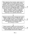
- FIG. 1 is a schematic flow chart of a location update method according to an embodiment of the present invention. As shown in FIG. 1 , the location update method of this embodiment may include:
- the first request message is a tracking area update (Tracking Area Update, abbreviated as TAU) request message
- the second request message is a location update (Location Update) request message
- the first request message is a location area update (Location Area Update, abbreviated as LAU) request message
- the second request message is a tracking area update (Tracking Area Update, abbreviated as TAU) request message.
- the detecting that the location update needs to be performed in the first mobile communication network includes:
- the single-card dual-standby user equipment when detecting a location change of the single-card dual-standby user equipment in the first mobile communication network, the single-card dual-standby user equipment sends the first request message to the mobile management device in the first mobile communication network, where the location change includes a location area (Location Area, abbreviated as LA) change and a tracking area (Tracking Area, abbreviated as TA) change; or, when detecting timeout of the periodic update timer of the first mobile communication network, the single-card dual-standby user equipment sends the first request message to the mobile management device in the first mobile communication network.
- LA Location Area
- TA tracking Area
- the foregoing instruction information may be carried in an update type (Update Type) field of the first request message or may also be carried in a newly added field.
- the foregoing instruction information may specifically be a certain letter and its combination, or a certain number and its combination, or a certain combination of a letter, a symbol, and a number, for example, which may be "LAI+TAI".
- the periodic update timer reset instruction may specifically be a certain letter and its combination, or a certain number and its combination, or a certain combination of a letter, a symbol, and a number, which is used for indicating the update of the periodic update timer.
- the first mobile communication network is a 2G mobile communication network, and the second mobile communication network is a 3G mobile communication network; or the first mobile communication network is a 2G mobile communication network, and the second mobile communication network is a 4G mobile communication network; or the first mobile communication network is a 3G mobile communication network, and the second mobile communication network is a 4G mobile communication network; or the first mobile communication network is a 3G mobile communication network, and the second mobile communication network is a 2G mobile communication network; or the first mobile communication network is a 4G mobile communication network, and the second mobile communication network is a 3G mobile communication network; or the first mobile communication network is a 4G mobile communication network, and the second mobile communication network is a 2G mobile communication network.
- an executive subject of steps 101 to 103 is the single-card dual-standby user equipment.
- a location update of the single-card dual-standby user equipment is synchronously implemented in the first mobile communication network and in the second mobile communication network, which can avoid a problem in the prior art that the single-card dual-standby user equipment is continually activated to execute the location update, thereby effectively reducing unnecessary electric energy loss of the single-card dual-standby user equipment.
- FIG. 2 is a schematic flow chart of a location update method according to another embodiment of the present invention. As shown in FIG. 2 , the location update method of this embodiment may include:
- the detecting, by the single-card dual-standby user equipment, that the location update needs to be performed in the first mobile communication network includes:
- the single-card dual-standby user equipment when detecting a location change of the single-card dual-standby user equipment in the first mobile communication network, the single-card dual-standby user equipment sends the first request message to a mobile management device in the first mobile communication network, where the location change includes a location area (Location Area, abbreviated as LA) change and a tracking area (Tracking Area, abbreviated as TA) change; or, when detecting timeout of the periodic update timer of the first mobile communication network, the single-card dual-standby user equipment may send the first request message to the mobile management device in the first mobile communication network.
- LA Location Area
- TA tracking Area
- the foregoing instruction information may be carried in an update type (Update Type) field of the first request message, or may also be carried in a newly added field.
- Update Type update type
- the first request message is a tracking area update request message
- the second request message is a location update request message
- the first request message is a location area update request message
- the second request message is a tracking area update request message
- the first mobile communication network is a 2G mobile communication network, and the second mobile communication network is a 3G mobile communication network; or the first mobile communication network is a 2G mobile communication network, and the second mobile communication network is a 4G mobile communication network; or the first mobile communication network is a 3G mobile communication network, and the second mobile communication network is a 4G mobile communication network; or the first mobile communication network is a 3G mobile communication network, and the second mobile communication network is a 2G mobile communication network; or the first mobile communication network is a 4G mobile communication network, and the second mobile communication network is a 3G mobile communication network; or the first mobile communication network is a 4G mobile communication network, and the second mobile communication network is a 2G mobile communication network.
- the executive subject of steps 201 to 203 is the mobile management device of the first mobile communication network.
- the mobile management device involved in this embodiment may be one of a mobility management entity (Mobility Management Entity, abbreviated as MME) or a mobile switch center (Mobile Switch Center, abbreviated as MSC), and may also have functions of MME and MSC at the same time.
- MME Mobility Management Entity
- MSC Mobile Switch Center
- the location update of the single-card dual-standby user equipment is synchronously implemented in the first mobile communication network and in the second mobile communication network, which can avoid a problem in the prior art that the single-card dual-standby user equipment is continually activated to execute the location update, thereby effectively reducing unnecessary electric energy loss of the single-card dual-standby user equipment.
- a circuit switched domain (Circuit Switched Domain, abbreviated as CS domain) of the single-card dual-standby user equipment may preferentially be attached to the 3G mobile communication network and preferentially carry CS domain services through the 3G mobile communication network, where a mobile management device of the CS domain in the 3G mobile communication network is a mobile switching center (Mobile Switching Center, abbreviated as MSC).
- CS domain Circuit Switched Domain
- MSC Mobile Switching Center
- a packet switch domain (Packet Switch Domain, abbreviated as PS domain) of the single-card dual-standby user equipment may preferentially be attached to the 4G mobile communication network and preferentially carry PS domain services through the 4G mobile communication network, where a mobile management device of the PS domain in the 4G mobile communication network is a mobility management entity (Mobility Management Entity, abbreviated as MME).
- MME Mobility Management Entity
- FIG. 3 is a schematic flow chart of a location update method according to another embodiment of the present invention.
- a CS domain of a single-card dual-standby user equipment is attached to a wideband code division multiple access (Wideband Code Division Multiple Access, abbreviated as WCDMA) system
- a PS domain of the single-card dual-standby user equipment is attached to a long term evolution (Long Term Evolution, abbreviated as LTE) system.
- the location update method of this embodiment may include:
- the single-card dual-standby user equipment detects timeout of a periodic update timer of the LTE system.
- the single-card dual-standby user equipment sends a tracking area update request (Tracking Area Update Request, abbreviated as TAU Request) message to a target MME through the transfer of a target evolved Node B (Evolved Node B, abbreviated as eNB), where the tracking area update request message carries an update type field, and the update type field is used to instruct the target MME to execute a location update caused by the change of the tracking area (or timeout of the periodic update timer) and send a location update request (Location Update Request) message to an MSC.
- TAU Request Track Area Update Request
- eNB target evolved Node B
- the update type field is used to instruct the target MME to execute a location update caused by the change of the tracking area (or timeout of the periodic update timer) and send a location update request (Location Update Request) message to an MSC.
- the update type field may be "TAI+LAI".
- the tracking area update request message may further carry a newly added field, and the newly added field is used to instruct the target MME to send the location update request (Location Update Request) message to the MSC.
- the target MME executes a location update caused by the change of the tracking area.
- the target MME obtains a corresponding MSC address according to a location area identity (Location Area Identity, abbreviated as LAI).
- LAI Location Area Identity
- the target MME sends a location update request message to an MSC corresponding to the MSC address, where the location update request message carries the update type field and is used to instruct the MSC to execute a location update caused by the timeout of the periodic update timer.
- the MSC resets a periodic update timer T3312.
- the MSC sends a location update accept (Location Update Accept) message to the target MME.
- the target MME sends a tracking area update accept (TAU Accept) message to the single-card dual-standby user equipment through the transfer of the target evolved Node B (Evolved Node B, abbreviated as eNB), where the tracking area update accept message carries a periodic update timer T3312 reset instruction.
- TAU Accept tracking area update accept
- the single-card dual-standby user equipment also executes in the WCDMA system the location update caused by the timeout of the periodic update timer while executing in the LTE system the location update caused by the location change or the timeout of the periodic update timer.
- the single-card dual-standby user equipment sends a tracking area update request message to the target MME in the LTE system, where the tracking area update request message includes WCDMA system location update instruction information, so that the target MME can send a location update request message to the MSC in the WCDMA system, so as to implement the synchronous location update of the single-card dual-standby user equipment in the LTE system and in the WCDMA system, which can avoid a problem in the prior art that the single-card dual-standby user equipment is continually activated to execute the location update, thereby effectively reducing unnecessary electric energy loss of the single-card dual-standby user equipment.
- FIG. 4 is a schematic flow chart of a location update method according to another embodiment of the present invention.
- a CS domain of a single-card dual-standby user equipment is attached to a wideband code division multiple access (Wideband Code Division Multiple Access, abbreviated as WCDMA) system
- a PS domain of the single-card dual-standby user equipment is attached to a long term evolution (Long Term Evolution, abbreviated as LTE) system.
- the location update method of this embodiment may include:
- the single-card dual-standby user equipment may also detect timeout of a periodic update timer of the WCDMA system.
- the single-card dual-standby user equipment sends a location area update request (Location Area Update Request, abbreviated as LAU Request) message to a target MSC (an MSC of another mobile network) through the transfer of a target radio network controller (Radio Network Controller, abbreviated as RNC), where the location area update request message carries an update type field, and the update type field is used to instruct the target MSC to execute a location update caused by the change of the location area(or the timeout of the periodic update timer) and send a tracking area update request (Tracking Area Update Request, abbreviated as TAU Request) message to an MME.
- LAU Request Location Area Update Request
- RNC Radio Network Controller
- the update type field may be "LAI+TAI".
- the tracking area request message may further carry a newly added field, and the newly added field is used to instruct the target MSC to execute a location update caused by the change of the location area and send a tracking area update request (Tracking Area Update Request, abbreviated as TAU Request) message to the MME.
- TAU Request Tracking Area Update Request
- the target MSC executes a location update caused by the change of the location area.
- the target MSC obtains a corresponding MME address according to a tracking area identity (Tracking Area Identity, abbreviated as TAI).
- TAI Tracking Area Identity
- the target MSC sends a tracking area update request message to an MME corresponding to the MME address, where the tracking area update request message carries an update type field and is used to instruct the MME to execute a location update caused by the timeout of the periodic update timer.
- the MME resets a periodic update timer T3412.
- the MME sends a tracking area update accept (TAU Accept) message to the target MSC.
- TAU Accept tracking area update accept
- the target MSC sends a location update accept (Location Update Accept) message to the single-card dual-standby user equipment through the transfer of a target radio network controller (Radio Network Controller, abbreviated as RNC), where the message carries a periodic update timer T3412 reset instruction.
- RNC Radio Network Controller
- the single-card dual-standby user equipment also executes in the LTE system the location update caused by the timeout of the periodic update timer while executing in the WCDMA system the location update caused by the location change or the timeout of the periodic update timer.
- the single-card dual-standby user equipment sends a location area update request message to the target MSC in the WCDMA system, where the location area request message includes LTE system location update instruction information, so that the target MSC can send a tracking area request message to the MME in the LTE system, so as to implement the synchronous location update of the single-card dual-standby user equipment in the WCDMA system and in the LTE system, which can avoid a problem in the prior art that the single-card dual-standby user equipment is continually activated to execute the location update, thereby effectively reducing unnecessary electric energy loss of the single-card dual-standby user equipment.
- FIG. 5 is a schematic structural diagram of a single-card dual-standby user equipment according to another embodiment of the present invention, where the single-card dual-standby user equipment may include: at least one processor 52 and a radio frequency transceiver 51 which are coupled to each other through a bus 53.
- the single-card dual-standby user equipment may optionally include: a display controller and a display 54 that are coupled to other components through the bus 53; and one or more input/output (Input/Output, abbreviated as I/O) controllers 55 which are also coupled to the bus 53 to provide an interface to one or more input/output devices 56.
- the bus 53 may include one or more buses interconnected through various bridges, controllers, and/or adapters known in the art.
- An input/output device 56 may include a key area, a keyboard, a controller of a cursor, or a touchscreen.
- the processor 52 is further configured to, when the radio frequency transceiver 51 receives a second accept message including the periodic update timer reset instruction of the second mobile communication network and sent by the mobile management device in the first mobile communication network, reset the periodic update timer of the second mobile communication network according to the periodic update timer reset instruction of the second mobile communication network.
- the method in the embodiment corresponding to FIG. 1 , and the functions of the single-card dual-standby user equipment in the embodiments corresponding to FIG. 2 , FIG. 3 , and FIG. 4 may be implemented by the single-card dual-standby user equipment provided in this embodiment.
- the single-card dual-standby user equipment also includes:
- the processor 52 is further configured to detect whether a location in the first mobile communication network changes or detect whether a periodic update timer of the first mobile communication network times out.
- the single-card dual-standby user equipment provided in this embodiment implements a synchronous location update of the single-card dual-standby user equipment in the first mobile communication network and in the second mobile communication network, which can avoid a problem in the prior art that the single-card dual-standby user equipment is continually activated to execute the location update, thereby effectively reducing unnecessary electric energy loss of the single-card dual-standby user equipment.
- FIG. 6 is a schematic structural diagram of a mobile management device according to another embodiment of the present invention.
- the mobile management device may include: at least one processor 62 and a radio frequency transceiver 61 which are coupled to each other through a bus 63.
- the mobile management device may optionally include one or more input/output controllers 64 which are coupled to other components through the bus 63 to provide an interface for one or more input/output devices 65.
- the bus 63 may include one or more buses interconnected through various bridges, controllers, and/or adapters known in the art.
- An input/output device 65 may include a key area, a keyboard, a controller of a cursor, or a touchscreen.
- the radio frequency transceiver 61 is configured to send a second accept message including a periodic update timer reset instruction of the second mobile communication network to the single-card dual-standby user equipment when receiving a first accept message including the periodic update timer reset instruction of the second mobile communication network and sent by the mobile management device in the second mobile communication network, so that the single-card dual-standby user equipment resets the periodic update timer of the second mobile communication network according to the periodic update timer reset instruction of the second mobile communication network.
- the method in the embodiment corresponding to FIG. 2 , the mobile management device in the first mobile communication network in the embodiment corresponding to FIG. 1 , and the functions of the target MME in the embodiment corresponding to FIG. 3 and of the target MSC in the embodiment corresponding to FIG. 4 may be implemented by the mobile management device provided in this embodiment.
- the mobile management device provided in this embodiment implements a synchronous location update of the single-card dual-standby user equipment in the first mobile communication network and in the second mobile communication network, which can avoid a problem in the prior art that the single-card dual-standby user equipment is continually activated to execute the location update, thereby effectively reducing unnecessary electric energy loss of the single-card dual-standby user equipment.
- Another embodiment of the present invention provides a location update system, which may include the single-card dual-standby user equipment according to the embodiment corresponding to FIG. 5 and the mobile management device according to the embodiment corresponding to FIG. 6 .
- the location update system provided in another embodiment of the present invention implements a synchronous location update of the single-card dual-standby user equipment in the first mobile communication network and in the second mobile communication network, which can avoid a problem in the prior art that the single-card dual-standby user equipment is continually activated to execute the location update, thereby effectively reducing unnecessary electric energy loss of the single-card dual-standby user equipment.
- the disclosed system, apparatus, and method may be implemented in other manners.
- the described apparatus embodiments are merely exemplary.
- the unit division is merely logical function division and can be in another division manner in actual implementation.
- multiple units or components can be combined or can be integrated into another system, or some features can be ignored or not performed.
- the displayed or discussed mutual couplings or direct couplings or communication connections may be indirect couplings or communication connections through some interfaces, apparatuses, or units and may be in electronic, mechanical or other forms.
- the units described as separate parts may be or may not be physically separate, and parts displayed as units may be or may not be physical units, that is, may be located in one place, or may also be distributed onto multiple network elements. A part or all of the units may be selected according to the actual needs to achieve the objectives of the solutions of the embodiments.
- function units in the embodiments of the present invention may be integrated into a processing unit, each of the units may also individually exist physically, and two or more units may also be integrated into a unit.
- the foregoing integrated unit may be implemented by adopting a form of hardware, and may also be implemented by adopting a form of hardware plus a software functional unit.
- the integrated unit implemented in the form of the software functional unit may be stored in a computer readable storage medium.
- the software functional unit is stored in a storage medium, and includes several instructions which are used to instruct a computer device (which may be a personal computer, a server, or a network device) to perform the steps of the methods according to the embodiments of the present invention.
- the foregoing storage medium includes: any medium that can store program codes, such as a U disk, a removable hard disk, a read-only memory (Read-Only memory, abbreviated as ROM), a random access memory (Random Access Memory, abbreviated as RAM), a magnetic disk, or a compact disk.
Landscapes
- Engineering & Computer Science (AREA)
- Computer Networks & Wireless Communication (AREA)
- Signal Processing (AREA)
- Mobile Radio Communication Systems (AREA)
- Telephone Function (AREA)
- Telephonic Communication Services (AREA)
Abstract
Description
- Embodiments of the present invention relate to a communications technologies, and in particular, to a method, an apparatus, and a system for a location update.
- With the development of mobile communications technologies, based on the second-generation (2nd-generation, abbreviated as 2G) mobile communication network and the third-generation (3rd-generation, abbreviated as 3G) mobile communication network, a mobile communication network with higher and higher transmission rate, such as, a fourth-generation (4th-generation, abbreviated as 4G) mobile communication network, is widely applied increasingly. However, in a process of developing the high-speed mobile communication network such as the 4G mobile communication network, limited by various conditions, the existing low-speed mobile communication network cannot be completely upgraded to a new high-speed mobile communication network in a short time. Therefore, the foregoing high-speed mobile communication networks coexist with the existing low-speed mobile communication networks for a long time. Because a single-card dual-standby user equipment (User Equipment, abbreviated as UE) resides in two mobile communication networks, the single-card dual-standby user equipment needs to execute, in the two mobile communication networks, a location update caused by a location change and a location update caused by timeout of a periodic update timer.
- However, in a period after the location update caused by the location change is executed in one mobile communication network, the single-card dual-standby user equipment may also need to execute, in the other mobile communication network, the location update caused by the timeout of the periodic update timer. In this way, the single-card dual-standby user equipment is continually activated to execute the location update, resulting in unnecessary electric energy loss of the single-card dual-standby user equipment.
- Embodiments of the present invention provide a method, an apparatus, and a system for a location update, which are used to reduce unnecessary electric energy loss of a single-card dual-standby user equipment.
- In one aspect, a location update method is provided, which includes:
- when detecting that a location update needs to be performed in a first mobile communication network, sending a first request message including instruction information to a mobile management device in the first mobile communication network, so that the mobile management device in the first mobile communication network sends a second request message to a mobile management device in a second mobile communication network when executing the location update according to the instruction information, where the second request message enables the mobile management device in the second mobile communication network to reset a periodic update timer and send a first accept message including a periodic update timer reset instruction of the second mobile communication network to the mobile management device in the first mobile communication network;
- receiving a second accept message sent by the mobile management device in the first mobile communication network, where the second accept message includes the periodic update timer reset instruction of the second mobile communication network; and
- resetting the periodic update timer of the second mobile communication network according to the periodic update timer reset instruction of the second mobile communication network.
- In another aspect, a location update method is provided, which includes:
- receiving a first request message including instruction information, where the first request message is sent by a single-card dual-standby user equipment when detecting that a location update needs to be performed in a first mobile communication network;
- executing the location update according to the instruction information, and sending a second request message to a mobile management device in a second mobile communication network, so that the mobile management device in the second mobile communication network resets a periodic update timer;
- receiving a first accept message sent by the mobile management device in the second mobile communication network, where the first accept message includes a periodic update timer reset instruction of the second mobile communication network; and
- sending a second accept message including the periodic update timer reset instruction of the second mobile communication network to the single-card dual-standby user equipment, so that the single-card dual-standby user equipment resets the periodic update timer of the second mobile communication network according to the periodic update timer reset instruction of the second mobile communication network.
- In another aspect, a single-card dual-standby user equipment is provided, which includes:
- a radio frequency transceiver; and
- at least one processor, coupled to the radio frequency transceiver, where the processor is configured to, when detecting that a location update needs to be performed in a first mobile communication network, trigger the radio frequency transceiver to send a first request message including instruction information to a mobile management device in the first mobile communication network, so that the mobile management device in the first mobile communication network sends a second request message to a mobile management device in a second mobile communication network when executing the location update according to the instruction information, where the second request message enables the mobile management device in the second mobile communication network to reset a periodic update timer and send a first accept message including a periodic update timer reset instruction of the second mobile communication network to the mobile management device in the first mobile communication network; where
- the processor is further configured to, when the radio frequency transceiver receives a second accept message including the periodic update timer reset instruction of the second mobile communication network and sent by the mobile management device in the first mobile communication network, reset the periodic update timer of the second mobile communication network according to the periodic update timer reset instruction of the second mobile communication network.
- In another aspect, a mobile management device is provided, which includes:
- a radio frequency transceiver; and
- at least one processor, coupled to the radio frequency transceiver, where the processor is configured to, when the radio frequency transceiver receives a first request message including instruction information, where the first request message is sent by a single-card dual-standby user equipment when detecting that a location update needs to be performed in a first mobile communication network, execute the location update according to the instruction information, and trigger the radio frequency transceiver to send a second request message to a mobile management device in a second mobile communication network, so that the mobile management device in the second mobile communication network resets a periodic update timer; where
- the radio frequency transceiver is configured to send a second accept message including a periodic update timer reset instruction of the second mobile communication network to the single-card dual-standby user equipment when receiving a first accept message including the periodic update timer reset instruction of the second mobile communication network and sent by the mobile management device in the second mobile communication network, so that the single-card dual-standby user equipment resets the periodic update timer of the second mobile communication network according to the periodic update timer reset instruction of the second mobile communication network.
- In another aspect, a location update system is provided, which includes the foregoing single-card dual-standby user equipment and the foregoing mobile management device.
- It can be known from the foregoing technical solutions that, through the embodiments of the present invention, it is implemented that a location update of the single-card dual-standby user equipment is synchronously performed in the first mobile communication network and in the second mobile communication network, which can avoid a problem in the prior art that the single-card dual-standby user equipment is continually activated to execute the location update, thereby effectively reducing unnecessary electric energy loss of the single-card dual-standby user equipment.
- To illustrate the technical solutions in the embodiments of the present invention or in the prior art more clearly, the accompanying drawings required for describing the embodiments or the prior art are briefly introduced in the following. Apparently, the accompanying drawings in the following description are merely some embodiments of the present invention, and persons of ordinary skill in the art can further derive other drawings according to these accompanying drawings without making creative efforts.
-
FIG. 1 is a schematic flow chart of a location update method according to an embodiment of the present invention; -
FIG. 2 is a schematic flow chart of a location update method according to another embodiment of the present invention; -
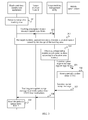
FIG. 3 is a schematic flow chart of a location update method according to another embodiment of the present invention; -
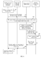
FIG. 4 is a schematic flow chart of a location update method according to another embodiment of the present invention; -
FIG. 5 is a schematic structural diagram of a single-card dual-standby user equipment according to another embodiment of the present invention; and -
FIG. 6 is a schematic structural diagram of a mobile management device according to another embodiment of the present invention. - To make the objectives, technical solutions, and advantages of the embodiments of the present invention clearer, the technical solutions according to the embodiments of the present invention are clearly and completely described in the following with reference to the accompanying drawings in the embodiments of the present invention. Apparently, the embodiments in the description are merely a part rather than all of the embodiments of the present invention. All other embodiments obtained by persons of ordinary skill in the art based on the embodiments of the present invention without making creative efforts shall fall within the protection scope of the present invention.
- It should be noted that, a single-card dual-standby user equipment involved in the embodiments of the present invention includes, but is not limit to, a wireless hand-hold device, a mobile telephone, a smart cell phone, a portable device, a networking card, or a data card.
- A location update involved in the embodiments of the present invention is that a user equipment must register in a new location area when the user equipment moves from one location area to another location area. That is to say, once the user equipment has a certain need or finds that a location area identity (Location Area Identity, abbreviated as LAI) in its memory and a received LAI of a current cell changes, the network must be informed of changing the location information which is of the user equipment and is stored in the network. This process is the location update. According to different identifications of the location update by the network, the location update may be classified into three types: a normal location update (that is, location update cross the location areas), a periodic location update, and an international mobile subscriber identification number (International Mobile Subscriber Identification Number, abbreviated as IMSI) attachment and separation (correspond to subscriber boot). For example, in a circuit domain of a GSM or a UMTS, a location of the single-card dual-standby user equipment is referred to as a location area, and correspondingly, in the circuit domain of the GSM or the UMTS, the location update of the single-card dual-standby user equipment is referred to as a location area update. In the LTE, a location of the single-card dual-standby user equipment is referred to as a tracking area; and correspondingly, in the LTE, the location update of the single-card dual-standby user equipment is referred to as a tracking area update.
-
FIG. 1 is a schematic flow chart of a location update method according to an embodiment of the present invention. As shown inFIG. 1 , the location update method of this embodiment may include: - 101: When detecting that a location update needs to be performed in a first mobile communication network, send a first request message including instruction information to a mobile management device in the foregoing first mobile communication network, so that the mobile management device in the first mobile communication network sends a second request message to a mobile management device in a second mobile communication network when executing the location update according to the instruction information, where the second request message enables the mobile management device in the second mobile communication network to reset a periodic update timer and send a first accept message including a periodic update timer reset instruction of the second mobile communication network to the mobile management device in the first mobile communication network;
- Optionally, the first request message is a tracking area update (Tracking Area Update, abbreviated as TAU) request message, and the second request message is a location update (Location Update) request message; or the first request message is a location area update (Location Area Update, abbreviated as LAU) request message, and the second request message is a tracking area update (Tracking Area Update, abbreviated as TAU) request message.
- The detecting that the location update needs to be performed in the first mobile communication network includes:
- detecting a location change in the first mobile communication network; or
- detecting timeout of a periodic update timer of the first mobile communication network.
- Specifically, when detecting a location change of the single-card dual-standby user equipment in the first mobile communication network, the single-card dual-standby user equipment sends the first request message to the mobile management device in the first mobile communication network, where the location change includes a location area (Location Area, abbreviated as LA) change and a tracking area (Tracking Area, abbreviated as TA) change;
or,
when detecting timeout of the periodic update timer of the first mobile communication network, the single-card dual-standby user equipment sends the first request message to the mobile management device in the first mobile communication network. - Optionally, the foregoing instruction information may be carried in an update type (Update Type) field of the first request message or may also be carried in a newly added field. The foregoing instruction information may specifically be a certain letter and its combination, or a certain number and its combination, or a certain combination of a letter, a symbol, and a number, for example, which may be "LAI+TAI".
- 102: Receive a second accept message sent by the mobile management device in the first mobile communication network, where the second accept message includes a periodic update timer reset instruction of the second mobile communication network.
- It should be noted that, the periodic update timer reset instruction may specifically be a certain letter and its combination, or a certain number and its combination, or a certain combination of a letter, a symbol, and a number, which is used for indicating the update of the periodic update timer.
- 103: Reset the periodic update timer of the second mobile communication network according to the periodic update timer reset instruction of the second mobile communication network.
- The first mobile communication network is a 2G mobile communication network, and the second mobile communication network is a 3G mobile communication network; or the first mobile communication network is a 2G mobile communication network, and the second mobile communication network is a 4G mobile communication network; or the first mobile communication network is a 3G mobile communication network, and the second mobile communication network is a 4G mobile communication network; or the first mobile communication network is a 3G mobile communication network, and the second mobile communication network is a 2G mobile communication network; or the first mobile communication network is a 4G mobile communication network, and the second mobile communication network is a 3G mobile communication network; or the first mobile communication network is a 4G mobile communication network, and the second mobile communication network is a 2G mobile communication network.
- It should be noted that, an executive subject of steps 101 to 103 is the single-card dual-standby user equipment.
- Through the technical solutions provided in this embodiment, a location update of the single-card dual-standby user equipment is synchronously implemented in the first mobile communication network and in the second mobile communication network, which can avoid a problem in the prior art that the single-card dual-standby user equipment is continually activated to execute the location update, thereby effectively reducing unnecessary electric energy loss of the single-card dual-standby user equipment.
-
FIG. 2 is a schematic flow chart of a location update method according to another embodiment of the present invention. As shown inFIG. 2 , the location update method of this embodiment may include: - 201: Receive a first request message including instruction information, where the first request message is sent by a single-card dual-standby user equipment when detecting that a location update needs to be performed in a first mobile communication network.
- The detecting, by the single-card dual-standby user equipment, that the location update needs to be performed in the first mobile communication network includes:
- detecting, by the single-card dual-standby user equipment, a location change in the first mobile communication network; or
- detecting, by the single-card dual-standby user equipment, timeout of a periodic update timer of the first mobile communication network.
- Specifically, when detecting a location change of the single-card dual-standby user equipment in the first mobile communication network, the single-card dual-standby user equipment sends the first request message to a mobile management device in the first mobile communication network, where the location change includes a location area (Location Area, abbreviated as LA) change and a tracking area (Tracking Area, abbreviated as TA) change;
or,
when detecting timeout of the periodic update timer of the first mobile communication network, the single-card dual-standby user equipment may send the first request message to the mobile management device in the first mobile communication network. - Optionally, the foregoing instruction information may be carried in an update type (Update Type) field of the first request message, or may also be carried in a newly added field.
- 202: Execute the location update according to the instruction information, and send a second request message to a mobile management device in a second mobile communication network, so that the mobile management device in the second mobile communication network resets a periodic update timer.
- Optionally, the first request message is a tracking area update request message, and the second request message is a location update request message; or the first request message is a location area update request message, and the second request message is a tracking area update request message.
- 203: Receive a first accept message sent by the mobile management device in the second mobile communication network, where the first accept message includes a periodic update timer reset instruction of the second mobile communication network.
- 204: Send a second accept message including the periodic update timer reset instruction of the second mobile communication network to the single-card dual-standby user equipment, so that the single-card dual-standby user equipment resets the periodic update timer of the second mobile communication network according to the periodic update timer reset instruction of the second mobile communication network.
- The first mobile communication network is a 2G mobile communication network, and the second mobile communication network is a 3G mobile communication network; or the first mobile communication network is a 2G mobile communication network, and the second mobile communication network is a 4G mobile communication network; or the first mobile communication network is a 3G mobile communication network, and the second mobile communication network is a 4G mobile communication network; or the first mobile communication network is a 3G mobile communication network, and the second mobile communication network is a 2G mobile communication network; or the first mobile communication network is a 4G mobile communication network, and the second mobile communication network is a 3G mobile communication network; or the first mobile communication network is a 4G mobile communication network, and the second mobile communication network is a 2G mobile communication network.
- It should be noted that, the executive subject of
steps 201 to 203 is the mobile management device of the first mobile communication network. It should be noted that, the mobile management device involved in this embodiment may be one of a mobility management entity (Mobility Management Entity, abbreviated as MME) or a mobile switch center (Mobile Switch Center, abbreviated as MSC), and may also have functions of MME and MSC at the same time. - Through the technical solutions provided in this embodiment, the location update of the single-card dual-standby user equipment is synchronously implemented in the first mobile communication network and in the second mobile communication network, which can avoid a problem in the prior art that the single-card dual-standby user equipment is continually activated to execute the location update, thereby effectively reducing unnecessary electric energy loss of the single-card dual-standby user equipment.
- In order to make the method provided in the embodiment of the present invention clearer, an upgrade from a 3G mobile communication network to a 4G mobile communication network is taken as an example in the following. In a general case, a circuit switched domain (Circuit Switched Domain, abbreviated as CS domain) of the single-card dual-standby user equipment may preferentially be attached to the 3G mobile communication network and preferentially carry CS domain services through the 3G mobile communication network, where a mobile management device of the CS domain in the 3G mobile communication network is a mobile switching center (Mobile Switching Center, abbreviated as MSC). A packet switch domain (Packet Switch Domain, abbreviated as PS domain) of the single-card dual-standby user equipment may preferentially be attached to the 4G mobile communication network and preferentially carry PS domain services through the 4G mobile communication network, where a mobile management device of the PS domain in the 4G mobile communication network is a mobility management entity (Mobility Management Entity, abbreviated as MME). Since the single-card dual-standby user equipment resides in the 3G mobile communication network and the 4G mobile communication network, respectively, the single-card dual-standby user equipment needs to execute a location update caused by a location change and a location update caused by timeout of a periodic update timer in the 3G mobile communication network and in the 4G mobile communication network, respectively.
-
FIG. 3 is a schematic flow chart of a location update method according to another embodiment of the present invention. In this embodiment, a CS domain of a single-card dual-standby user equipment is attached to a wideband code division multiple access (Wideband Code Division Multiple Access, abbreviated as WCDMA) system, and a PS domain of the single-card dual-standby user equipment is attached to a long term evolution (Long Term Evolution, abbreviated as LTE) system. As shown inFIG. 3 , the location update method of this embodiment may include: - 301: The single-card dual-standby user equipment detects a change of a tracking area (Tracking Area, abbreviated as TA).
- Alternatively, the single-card dual-standby user equipment detects timeout of a periodic update timer of the LTE system.
- 302: The single-card dual-standby user equipment sends a tracking area update request (Tracking Area Update Request, abbreviated as TAU Request) message to a target MME through the transfer of a target evolved Node B (Evolved Node B, abbreviated as eNB), where the tracking area update request message carries an update type field, and the update type field is used to instruct the target MME to execute a location update caused by the change of the tracking area (or timeout of the periodic update timer) and send a location update request (Location Update Request) message to an MSC.
- For example, the update type field may be "TAI+LAI".
- Alternatively, the tracking area update request message may further carry a newly added field, and the newly added field is used to instruct the target MME to send the location update request (Location Update Request) message to the MSC.
- 303: The target MME executes a location update caused by the change of the tracking area.
- 304: The target MME obtains a corresponding MSC address according to a location area identity (Location Area Identity, abbreviated as LAI).
- 305: According to the obtained MSC address, the target MME sends a location update request message to an MSC corresponding to the MSC address, where the location update request message carries the update type field and is used to instruct the MSC to execute a location update caused by the timeout of the periodic update timer.
- 306: The MSC resets a periodic update timer T3312.
- 307: The MSC sends a location update accept (Location Update Accept) message to the target MME.
- 308: The target MME sends a tracking area update accept (TAU Accept) message to the single-card dual-standby user equipment through the transfer of the target evolved Node B (Evolved Node B, abbreviated as eNB), where the tracking area update accept message carries a periodic update timer T3312 reset instruction.
- 309: The single-card dual-standby user equipment resets the periodic update timer T3312.
- Therefore, the single-card dual-standby user equipment also executes in the WCDMA system the location update caused by the timeout of the periodic update timer while executing in the LTE system the location update caused by the location change or the timeout of the periodic update timer.
- In this embodiment, during a location update process caused by the change of the tracking area in the LTE system, the single-card dual-standby user equipment sends a tracking area update request message to the target MME in the LTE system, where the tracking area update request message includes WCDMA system location update instruction information, so that the target MME can send a location update request message to the MSC in the WCDMA system, so as to implement the synchronous location update of the single-card dual-standby user equipment in the LTE system and in the WCDMA system, which can avoid a problem in the prior art that the single-card dual-standby user equipment is continually activated to execute the location update, thereby effectively reducing unnecessary electric energy loss of the single-card dual-standby user equipment.
-
FIG. 4 is a schematic flow chart of a location update method according to another embodiment of the present invention. In this embodiment, a CS domain of a single-card dual-standby user equipment is attached to a wideband code division multiple access (Wideband Code Division Multiple Access, abbreviated as WCDMA) system, and a PS domain of the single-card dual-standby user equipment is attached to a long term evolution (Long Term Evolution, abbreviated as LTE) system. As shown inFIG. 4 , the location update method of this embodiment may include: - 401: The single-card dual-standby user equipment detects a change of a location area (Location Area, abbreviated as LA).
- Alternatively, the single-card dual-standby user equipment may also detect timeout of a periodic update timer of the WCDMA system.
- 402: The single-card dual-standby user equipment sends a location area update request (Location Area Update Request, abbreviated as LAU Request) message to a target MSC (an MSC of another mobile network) through the transfer of a target radio network controller (Radio Network Controller, abbreviated as RNC), where the location area update request message carries an update type field, and the update type field is used to instruct the target MSC to execute a location update caused by the change of the location area(or the timeout of the periodic update timer) and send a tracking area update request (Tracking Area Update Request, abbreviated as TAU Request) message to an MME.
- For example, the update type field may be "LAI+TAI".
- Alternatively, the tracking area request message may further carry a newly added field, and the newly added field is used to instruct the target MSC to execute a location update caused by the change of the location area and send a tracking area update request (Tracking Area Update Request, abbreviated as TAU Request) message to the MME.
- 403: The target MSC executes a location update caused by the change of the location area.
- 404: The target MSC obtains a corresponding MME address according to a tracking area identity (Tracking Area Identity, abbreviated as TAI).
- 405: According to the obtained MME address, the target MSC sends a tracking area update request message to an MME corresponding to the MME address, where the tracking area update request message carries an update type field and is used to instruct the MME to execute a location update caused by the timeout of the periodic update timer.
- 406: The MME resets a periodic update timer T3412.
- 407: The MME sends a tracking area update accept (TAU Accept) message to the target MSC.
- 408: The target MSC sends a location update accept (Location Update Accept) message to the single-card dual-standby user equipment through the transfer of a target radio network controller (Radio Network Controller, abbreviated as RNC), where the message carries a periodic update timer T3412 reset instruction.
- 409: The single-card dual-standby user equipment resets the periodic update timer T3412.
- Therefore, the single-card dual-standby user equipment also executes in the LTE system the location update caused by the timeout of the periodic update timer while executing in the WCDMA system the location update caused by the location change or the timeout of the periodic update timer.
- In this embodiment, during a location update process caused by the change of the location area in the WCDMA system, the single-card dual-standby user equipment sends a location area update request message to the target MSC in the WCDMA system, where the location area request message includes LTE system location update instruction information, so that the target MSC can send a tracking area request message to the MME in the LTE system, so as to implement the synchronous location update of the single-card dual-standby user equipment in the WCDMA system and in the LTE system, which can avoid a problem in the prior art that the single-card dual-standby user equipment is continually activated to execute the location update, thereby effectively reducing unnecessary electric energy loss of the single-card dual-standby user equipment.
- It should be noted that, for convenience of brief description, the foregoing method embodiments are described as a series of action combinations. However, it should be known by persons skilled in the art that the present invention is not limited by the order of the described actions because some steps may be performed in other orders or performed synchronously according to the present invention. Next, it should also be known by persons skilled in the art that the described embodiments in the specification all belong to exemplary embodiments, and the involved actions and modules are not necessarily required in the present invention.
- In the foregoing embodiments, the description of each embodiment has its emphasis, and for a part that is not described in detail in a certain embodiment, reference may be made to the relevant description of other embodiments.
-
FIG. 5 is a schematic structural diagram of a single-card dual-standby user equipment according to another embodiment of the present invention, where the single-card dual-standby user equipment may include: at least oneprocessor 52 and aradio frequency transceiver 51 which are coupled to each other through abus 53. - The single-card dual-standby user equipment may optionally include: a display controller and a
display 54 that are coupled to other components through thebus 53; and one or more input/output (Input/Output, abbreviated as I/O)controllers 55 which are also coupled to thebus 53 to provide an interface to one or more input/output devices 56. Thebus 53 may include one or more buses interconnected through various bridges, controllers, and/or adapters known in the art. An input/output device 56 may include a key area, a keyboard, a controller of a cursor, or a touchscreen. - The single-card dual-standby user equipment of this embodiment includes:
- a
radio frequency transceiver 51; and - at least one
processor 52, coupled to theradio frequency transceiver 51, where theprocessor 52 is configured to, when detecting that a location update needs to be performed in a first mobile communication network, trigger theradio frequency transceiver 51 to send a first request message including instruction information to a mobile management device in the first mobile communication network, so that the mobile management device in the first mobile communication network sends a second request message to a mobile management device in a second mobile communication network when executing the location update according to the instruction information, where the second request message enables the mobile management device in the second mobile communication network to reset a periodic update timer and send a first accept message including a periodic update timer reset instruction of the second mobile communication network to the mobile management device in the first mobile communication network; - The
processor 52 is further configured to, when theradio frequency transceiver 51 receives a second accept message including the periodic update timer reset instruction of the second mobile communication network and sent by the mobile management device in the first mobile communication network, reset the periodic update timer of the second mobile communication network according to the periodic update timer reset instruction of the second mobile communication network. - The method in the embodiment corresponding to
FIG. 1 , and the functions of the single-card dual-standby user equipment in the embodiments corresponding toFIG. 2 ,FIG. 3 , andFIG. 4 may be implemented by the single-card dual-standby user equipment provided in this embodiment. - Optionally, as shown in
FIG. 5 , the single-card dual-standby user equipment according to this embodiment also includes: - a display and a
display controller 54 which are coupled to the processor. - The
processor 52 is further configured to detect whether a location in the first mobile communication network changes or detect whether a periodic update timer of the first mobile communication network times out. - The single-card dual-standby user equipment provided in this embodiment implements a synchronous location update of the single-card dual-standby user equipment in the first mobile communication network and in the second mobile communication network, which can avoid a problem in the prior art that the single-card dual-standby user equipment is continually activated to execute the location update, thereby effectively reducing unnecessary electric energy loss of the single-card dual-standby user equipment.
-
FIG. 6 is a schematic structural diagram of a mobile management device according to another embodiment of the present invention. As shown inFIG. 6 , the mobile management device may include: at least oneprocessor 62 and aradio frequency transceiver 61 which are coupled to each other through a bus 63. - The mobile management device may optionally include one or more input/
output controllers 64 which are coupled to other components through the bus 63 to provide an interface for one or more input/output devices 65. The bus 63 may include one or more buses interconnected through various bridges, controllers, and/or adapters known in the art. An input/output device 65 may include a key area, a keyboard, a controller of a cursor, or a touchscreen. - The mobile management device of this embodiment includes:
- a
radio frequency transceiver 61, and - at least one
processor 62, coupled to theradio frequency transceiver 61, where theprocessor 62 is configured to, when theradio frequency transceiver 61 receives a first request message including instruction information, where the first request message is sent by a single-card dual-standby user equipment when detecting that a location update needs to be performed in a first mobile communication network, execute the location update according to the instruction information, and trigger theradio frequency transceiver 61 to send a second request message to a mobile management device in a second mobile communication network, so that the mobile management device in the second mobile communication network resets a periodic update timer; - The
radio frequency transceiver 61 is configured to send a second accept message including a periodic update timer reset instruction of the second mobile communication network to the single-card dual-standby user equipment when receiving a first accept message including the periodic update timer reset instruction of the second mobile communication network and sent by the mobile management device in the second mobile communication network, so that the single-card dual-standby user equipment resets the periodic update timer of the second mobile communication network according to the periodic update timer reset instruction of the second mobile communication network. - The method in the embodiment corresponding to
FIG. 2 , the mobile management device in the first mobile communication network in the embodiment corresponding toFIG. 1 , and the functions of the target MME in the embodiment corresponding toFIG. 3 and of the target MSC in the embodiment corresponding toFIG. 4 may be implemented by the mobile management device provided in this embodiment. - The mobile management device provided in this embodiment implements a synchronous location update of the single-card dual-standby user equipment in the first mobile communication network and in the second mobile communication network, which can avoid a problem in the prior art that the single-card dual-standby user equipment is continually activated to execute the location update, thereby effectively reducing unnecessary electric energy loss of the single-card dual-standby user equipment.
- Another embodiment of the present invention provides a location update system, which may include the single-card dual-standby user equipment according to the embodiment corresponding to
FIG. 5 and the mobile management device according to the embodiment corresponding toFIG. 6 . The location update system provided in another embodiment of the present invention implements a synchronous location update of the single-card dual-standby user equipment in the first mobile communication network and in the second mobile communication network, which can avoid a problem in the prior art that the single-card dual-standby user equipment is continually activated to execute the location update, thereby effectively reducing unnecessary electric energy loss of the single-card dual-standby user equipment. - It can be clearly understood by persons skilled in the art that, for the purpose of convenient and brief description, for a specific working process of the foregoing-described system, apparatus and unit, reference may be made to the corresponding process in the method embodiments, which is not repeatedly described here again.
- In the embodiments provided in the present application, it should be understood that the disclosed system, apparatus, and method may be implemented in other manners. For example, the described apparatus embodiments are merely exemplary. For example, the unit division is merely logical function division and can be in another division manner in actual implementation. For example, multiple units or components can be combined or can be integrated into another system, or some features can be ignored or not performed. In addition, the displayed or discussed mutual couplings or direct couplings or communication connections may be indirect couplings or communication connections through some interfaces, apparatuses, or units and may be in electronic, mechanical or other forms.
- The units described as separate parts may be or may not be physically separate, and parts displayed as units may be or may not be physical units, that is, may be located in one place, or may also be distributed onto multiple network elements. A part or all of the units may be selected according to the actual needs to achieve the objectives of the solutions of the embodiments.
- In addition, function units in the embodiments of the present invention may be integrated into a processing unit, each of the units may also individually exist physically, and two or more units may also be integrated into a unit. The foregoing integrated unit may be implemented by adopting a form of hardware, and may also be implemented by adopting a form of hardware plus a software functional unit.
- The integrated unit implemented in the form of the software functional unit may be stored in a computer readable storage medium. The software functional unit is stored in a storage medium, and includes several instructions which are used to instruct a computer device (which may be a personal computer, a server, or a network device) to perform the steps of the methods according to the embodiments of the present invention. The foregoing storage medium includes: any medium that can store program codes, such as a U disk, a removable hard disk, a read-only memory (Read-Only memory, abbreviated as ROM), a random access memory (Random Access Memory, abbreviated as RAM), a magnetic disk, or a compact disk.
- Finally, it should be noted that the foregoing embodiments are merely used for describing the technical solutions of the present invention, and not intended to limit the present invention. Although the present invention is described in detail with reference to the foregoing embodiments, persons of ordinary skill in the art should understand that they can still make modifications to the technical solutions recorded in the foregoing embodiments, or make equivalent replacements to some technical features of the technical solutions in the embodiments, and these modifications or replacements do not make the essence of the corresponding technical solutions depart from the spirit and scope of the technical solutions of the embodiments of the present invention.
Claims (10)
- A location update method, comprising:when detecting that a location update needs to be performed in a first mobile communication network, sending a first request message comprising instruction information to a mobile management device in the first mobile communication network, so that the mobile management device in the first mobile communication network sends a second request message to a mobile management device in a second mobile communication network when executing the location update according to the instruction information, wherein the second request message enables the mobile management device in the second mobile communication network to reset a periodic update timer and send a first accept message comprising a periodic update timer reset instruction of the second mobile communication network to the mobile management device in the first mobile communication network;receiving a second accept message sent by the mobile management device in the first mobile communication network, wherein the second accept message comprises the periodic update timer reset instruction of the second mobile communication network; andresetting the periodic update timer of the second mobile communication network according to the periodic update timer reset instruction of the second mobile communication network.
- The method according to claim 1, wherein the detecting that the location update needs to be performed in the first mobile communication network comprises:detecting a location change in the first mobile communication network; ordetecting timeout of a periodic update timer of the first mobile communication network.
- The method according to claim 1 or 2, wherein
the first request message is a tracking area update request message, and the second request message is a location update request message; or
the first request message is a location area update request message, and the second request message is a tracking area update request message. - The method according to claim 1 or 2, wherein the instruction information is carried in an update type field or a newly added field of the first request message.
- A location update method, comprising:receiving a first request message comprising instruction information, where the first request message is sent by a single-card dual-standby user equipment when detecting that a location update needs to be performed in a first mobile communication network;executing the location update according to the instruction information, and sending a second request message to a mobile management device in a second mobile communication network, so that the mobile management device in the second mobile communication network resets a periodic update timer;receiving a first accept message sent by the mobile management device in the second mobile communication network, wherein the first accept message comprises a periodic update timer reset instruction of the second mobile communication network; andsending a second accept message comprising the periodic update timer reset instruction of the second mobile communication network to the single-card dual-standby user equipment, so that the single-card dual-standby user equipment resets the periodic update timer of the second mobile communication network according to the periodic update timer reset instruction of the second mobile communication network.
- The method according to claim 5, wherein
the first request message is a tracking area update request message, and the second request message is a location update request message; or
the first request message is a location area update request message, and the second request message is a tracking area update request message. - A single-card dual-standby user equipment, comprising:a radio frequency transceiver; andat least one processor, coupled to the radio frequency transceiver, wherein the processor is configured to, when detecting that a location update needs to be performed in a first mobile communication network, trigger the radio frequency transceiver to send a first request message comprising instruction information to a mobile management device in the first mobile communication network, so that the mobile management device in the first mobile communication network sends a second request message to a mobile management device in a second mobile communication network when executing the location update according to the instruction information, wherein the second request message enables the mobile management device in the second mobile communication network to reset a periodic update timer and send a first accept message comprising a periodic update timer reset instruction of the second mobile communication network to the mobile management device in the first mobile communication network;wherein the processor is further configured to, when the radio frequency transceiver receives a second accept message comprising the periodic update timer reset instruction of the second mobile communication network and sent by the mobile management device in the first mobile communication network, reset the periodic update timer of the second mobile communication network according to the periodic update timer reset instruction of the second mobile communication network.
- The single-card dual-standby user equipment according to claim 7, further comprising:a display and a display controller that are coupled to the processor;wherein the processor is further configured to detect whether a location in the first mobile communication network changes or detect whether a periodic update timer of the first mobile communication network times out.
- A mobile management device, comprising:a radio frequency transceiver; andat least one processor, coupled to the radio frequency transceiver, wherein the processor is configured to, when the radio frequency transceiver receives a first request message comprising instruction information, where the first request message is sent by a single-card dual-standby user equipment when detecting that a location update needs to be performed in a first mobile communication network, execute the location update according to the instruction information, and trigger the radio frequency transceiver to send a second request message to a mobile management device in a second mobile communication network, so that the mobile management device in the second mobile communication network resets a periodic update timer;wherein the radio frequency transceiver is configured to send a second accept message comprising a periodic update timer reset instruction of the second mobile communication network to the single-card dual-standby user equipment when receiving a first accept message comprising the periodic update timer reset instruction of the second mobile communication network and sent by the mobile management device in the second mobile communication network, so that the single-card dual-standby user equipment resets the periodic update timer of the second mobile communication network according to the periodic update timer reset instruction of the second mobile communication network.
- A location update system, comprising the single-card dual-standby user equipment according to claim 7 or 8, and the mobile management device according to claim 9.
Applications Claiming Priority (1)
| Application Number | Priority Date | Filing Date | Title |
|---|---|---|---|
| PCT/CN2011/079626 WO2011157248A2 (en) | 2011-09-14 | 2011-09-14 | Location update method, device and system |
Publications (3)
| Publication Number | Publication Date |
|---|---|
| EP2713637A2 true EP2713637A2 (en) | 2014-04-02 |
| EP2713637A4 EP2713637A4 (en) | 2014-08-06 |
| EP2713637B1 EP2713637B1 (en) | 2018-03-14 |
Family
ID=45348655
Family Applications (1)
| Application Number | Title | Priority Date | Filing Date |
|---|---|---|---|
| EP11795214.3A Active EP2713637B1 (en) | 2011-09-14 | 2011-09-14 | Location update method and system |
Country Status (4)
| Country | Link |
|---|---|
| US (1) | US9148868B2 (en) |
| EP (1) | EP2713637B1 (en) |
| CN (1) | CN102440046B (en) |
| WO (1) | WO2011157248A2 (en) |
Cited By (2)
| Publication number | Priority date | Publication date | Assignee | Title |
|---|---|---|---|---|
| US10219148B2 (en) | 2015-05-20 | 2019-02-26 | Fujitsu Limited | Mobility support for virtual terminals |
| US10462763B2 (en) | 2016-07-25 | 2019-10-29 | Telefonaktiebolaget Lm Ericsson (Publ) | Coordination of simultaneous multi-RAT camping |
Families Citing this family (5)
| Publication number | Priority date | Publication date | Assignee | Title |
|---|---|---|---|---|
| US9674653B2 (en) * | 2015-03-03 | 2017-06-06 | Facebook, Inc. | Techniques to manage client location detection |
| KR20160112143A (en) | 2015-03-18 | 2016-09-28 | 삼성전자주식회사 | Electronic device and method for updating screen of display panel thereof |
| EP3493568B1 (en) * | 2016-08-12 | 2021-03-03 | Huawei Technologies Co., Ltd. | Communication methods, terminal device and access-network device |
| CN110636579B (en) * | 2018-06-22 | 2021-07-09 | 华为技术有限公司 | Communication method, paging method, apparatus and system |
| CN114450980B (en) * | 2019-09-29 | 2024-05-03 | 上海诺基亚贝尔股份有限公司 | Method and apparatus for location area update |
Family Cites Families (14)
| Publication number | Priority date | Publication date | Assignee | Title |
|---|---|---|---|---|
| AU2000245676A1 (en) * | 2000-05-22 | 2001-12-03 | Nokia Corporation | System and method for providing a connection in a communication network |
| US7941142B2 (en) * | 2003-03-28 | 2011-05-10 | Fujitsu Limited | Mobile switchboard, mobile unit, mobile communication system, and position-registration extending method |
| WO2007079578A1 (en) * | 2006-01-10 | 2007-07-19 | Research In Motion Limited | System and method for routing an incoming call to a proper domain in a network environment including ims |
| US8571580B2 (en) * | 2006-06-01 | 2013-10-29 | Loopt Llc. | Displaying the location of individuals on an interactive map display on a mobile communication device |
| CN101166323B (en) * | 2006-10-17 | 2010-12-08 | 中兴通讯股份有限公司 | Periodic update method of dual-mode terminal and mobile communication system |
| CN101203024B (en) * | 2006-12-15 | 2012-05-23 | 华为技术有限公司 | Method and system for searching wireless network and multi-mode equipment |
| ATE519350T1 (en) * | 2007-12-19 | 2011-08-15 | Ericsson Telefon Ab L M | COORDINATION BETWEEN DOMAIN FOR MT AND MON CALLS |
| CN100556215C (en) | 2008-01-14 | 2009-10-28 | 嘉兴闻泰通讯科技有限公司 | The double card double standby mobile phone of single GSM communication module carries out the periodical location area method for updating |
| CN102282871A (en) * | 2009-01-13 | 2011-12-14 | 瑞典爱立信有限公司 | Enable subscribers to move around the radio network |
| EP3125610A1 (en) * | 2009-10-30 | 2017-02-01 | Interdigital Patent Holdings, Inc. | Method and apparatus for efficient signaling and usage of resources for wireless communications supporting circuit switched and packet switched sessions |
| CN102026366B (en) * | 2010-12-16 | 2014-02-26 | 华为技术有限公司 | Single-card dual-standby network registering method and network control equipment |
| CN102137459B (en) * | 2011-02-21 | 2013-12-04 | 华为技术有限公司 | Method as well as related system and device for ensuring CS (circuit-switched) domain of one-card double-standby terminal to reside in two networks simultaneously |
| CN102158934A (en) * | 2011-04-01 | 2011-08-17 | 华为技术有限公司 | Network selection method and equipment |
| CN102740267B (en) * | 2011-04-02 | 2016-02-24 | 华为终端有限公司 | Position update processing method and equipment |
-
2011
- 2011-09-14 CN CN201180002586.XA patent/CN102440046B/en active Active
- 2011-09-14 EP EP11795214.3A patent/EP2713637B1/en active Active
- 2011-09-14 WO PCT/CN2011/079626 patent/WO2011157248A2/en not_active Ceased
-
2013
- 2013-12-31 US US14/145,286 patent/US9148868B2/en active Active
Cited By (4)
| Publication number | Priority date | Publication date | Assignee | Title |
|---|---|---|---|---|
| US10219148B2 (en) | 2015-05-20 | 2019-02-26 | Fujitsu Limited | Mobility support for virtual terminals |
| US10462763B2 (en) | 2016-07-25 | 2019-10-29 | Telefonaktiebolaget Lm Ericsson (Publ) | Coordination of simultaneous multi-RAT camping |
| US10805896B2 (en) | 2016-07-25 | 2020-10-13 | Telefonaktiebolaget Lm Ericsson (Publ) | Coordination of simultaneous multi-RAT camping |
| US11197259B2 (en) | 2016-07-25 | 2021-12-07 | Telefonaktiebolaget Lm Ericsson (Publ) | Coordination of simultaneous multi-RAT camping |
Also Published As
| Publication number | Publication date |
|---|---|
| WO2011157248A2 (en) | 2011-12-22 |
| WO2011157248A3 (en) | 2012-08-30 |
| EP2713637A4 (en) | 2014-08-06 |
| US9148868B2 (en) | 2015-09-29 |
| CN102440046B (en) | 2015-04-15 |
| CN102440046A (en) | 2012-05-02 |
| US20140113658A1 (en) | 2014-04-24 |
| EP2713637B1 (en) | 2018-03-14 |
Similar Documents
| Publication | Publication Date | Title |
|---|---|---|
| US9148868B2 (en) | Method, apparatus, and system for location update | |
| RU2606882C2 (en) | Method of processing information on cost, device and system | |
| CN103582063B (en) | Mobile communication device and method for retrieving service applicable thereto | |
| JP6680548B2 (en) | Technology for dynamically supporting distinct authentication algorithms | |
| US9986465B2 (en) | Method and system for returning to long term evolution network and mobile switching center | |
| EP3179754B1 (en) | Controlling e-utra capability of user equipment in a visited network | |
| EP3687224A1 (en) | Cell selection method and terminal | |
| CN113228730A (en) | Communication method and device | |
| US9661489B2 (en) | Method and apparatus for controlling issuance of packet data protocol context | |
| US9398170B2 (en) | Method, apparatus, and system for processing charging information | |
| US9883051B2 (en) | Method and system for usage of manual PLMN selection mode | |
| US10506462B2 (en) | Method and terminal for determining frequency to be measured | |
| US9729503B2 (en) | Network name processing method and mobility management network element device | |
| EP3293997B1 (en) | Apparatus for identification in wireless network | |
| EP3846538A1 (en) | Method for controlling display of service identifier, and related product | |
| US20190110212A1 (en) | Method, apparatus, terminal and base station for wireless communication | |
| EP2852218B1 (en) | Apparatus and method to handle ping-pong effect in IRAT Hand Over | |
| CN103391578A (en) | Mobile communication device and processing method for joint networking or routing area update program | |
| EP2571318A2 (en) | Method for realizing location update, service support node and visitor location register thereof | |
| CN104780527B (en) | Network name processing method and mobility management network element device | |
| CN109275167B (en) | Core network selection method, device and network system | |
| CN102077666B (en) | Paging method, apparatus and mobile switching center, communication system | |
| CN102833722B (en) | Processing method and device for deleting location message |
Legal Events
| Date | Code | Title | Description |
|---|---|---|---|
| PUAI | Public reference made under article 153(3) epc to a published international application that has entered the european phase |
Free format text: ORIGINAL CODE: 0009012 |
|
| 17P | Request for examination filed |
Effective date: 20131223 |
|
| AK | Designated contracting states |
Kind code of ref document: A2 Designated state(s): AL AT BE BG CH CY CZ DE DK EE ES FI FR GB GR HR HU IE IS IT LI LT LU LV MC MK MT NL NO PL PT RO RS SE SI SK SM TR |
|
| A4 | Supplementary search report drawn up and despatched |
Effective date: 20140708 |
|
| RIC1 | Information provided on ipc code assigned before grant |
Ipc: H04W 8/02 20090101ALI20140702BHEP Ipc: H04W 4/02 20090101AFI20140702BHEP Ipc: H04W 88/02 20090101ALI20140702BHEP |
|
| DAX | Request for extension of the european patent (deleted) | ||
| 17Q | First examination report despatched |
Effective date: 20170215 |
|
| RIC1 | Information provided on ipc code assigned before grant |
Ipc: H04W 60/00 20090101AFI20170718BHEP |
|
| REG | Reference to a national code |
Ref country code: DE Ref legal event code: R079 Ref document number: 602011046528 Country of ref document: DE Free format text: PREVIOUS MAIN CLASS: H04W0004020000 Ipc: H04W0056000000 |
|
| GRAP | Despatch of communication of intention to grant a patent |
Free format text: ORIGINAL CODE: EPIDOSNIGR1 |
|
| INTG | Intention to grant announced |
Effective date: 20170921 |
|
| RIC1 | Information provided on ipc code assigned before grant |
Ipc: H04W 60/00 20090101ALI20170908BHEP Ipc: H04W 56/00 20090101AFI20170908BHEP |
|
| RAP1 | Party data changed (applicant data changed or rights of an application transferred) |
Owner name: HUAWEI DEVICE (DONGGUAN) CO., LTD. |
|
| GRAS | Grant fee paid |
Free format text: ORIGINAL CODE: EPIDOSNIGR3 |
|
| GRAA | (expected) grant |
Free format text: ORIGINAL CODE: 0009210 |
|
| AK | Designated contracting states |
Kind code of ref document: B1 Designated state(s): AL AT BE BG CH CY CZ DE DK EE ES FI FR GB GR HR HU IE IS IT LI LT LU LV MC MK MT NL NO PL PT RO RS SE SI SK SM TR |
|
| REG | Reference to a national code |
Ref country code: GB Ref legal event code: FG4D |
|
| REG | Reference to a national code |
Ref country code: CH Ref legal event code: EP Ref country code: AT Ref legal event code: REF Ref document number: 980005 Country of ref document: AT Kind code of ref document: T Effective date: 20180315 |
|
| REG | Reference to a national code |
Ref country code: IE Ref legal event code: FG4D |
|
| REG | Reference to a national code |
Ref country code: DE Ref legal event code: R096 Ref document number: 602011046528 Country of ref document: DE |
|
| REG | Reference to a national code |
Ref country code: NL Ref legal event code: MP Effective date: 20180314 |
|
| REG | Reference to a national code |
Ref country code: LT Ref legal event code: MG4D |
|
| PG25 | Lapsed in a contracting state [announced via postgrant information from national office to epo] |
Ref country code: ES Free format text: LAPSE BECAUSE OF FAILURE TO SUBMIT A TRANSLATION OF THE DESCRIPTION OR TO PAY THE FEE WITHIN THE PRESCRIBED TIME-LIMIT Effective date: 20180314 Ref country code: NO Free format text: LAPSE BECAUSE OF FAILURE TO SUBMIT A TRANSLATION OF THE DESCRIPTION OR TO PAY THE FEE WITHIN THE PRESCRIBED TIME-LIMIT Effective date: 20180614 Ref country code: HR Free format text: LAPSE BECAUSE OF FAILURE TO SUBMIT A TRANSLATION OF THE DESCRIPTION OR TO PAY THE FEE WITHIN THE PRESCRIBED TIME-LIMIT Effective date: 20180314 Ref country code: FI Free format text: LAPSE BECAUSE OF FAILURE TO SUBMIT A TRANSLATION OF THE DESCRIPTION OR TO PAY THE FEE WITHIN THE PRESCRIBED TIME-LIMIT Effective date: 20180314 Ref country code: LT Free format text: LAPSE BECAUSE OF FAILURE TO SUBMIT A TRANSLATION OF THE DESCRIPTION OR TO PAY THE FEE WITHIN THE PRESCRIBED TIME-LIMIT Effective date: 20180314 Ref country code: CY Free format text: LAPSE BECAUSE OF FAILURE TO SUBMIT A TRANSLATION OF THE DESCRIPTION OR TO PAY THE FEE WITHIN THE PRESCRIBED TIME-LIMIT Effective date: 20180314 |
|
| REG | Reference to a national code |
Ref country code: AT Ref legal event code: MK05 Ref document number: 980005 Country of ref document: AT Kind code of ref document: T Effective date: 20180314 |
|
| PG25 | Lapsed in a contracting state [announced via postgrant information from national office to epo] |
Ref country code: BG Free format text: LAPSE BECAUSE OF FAILURE TO SUBMIT A TRANSLATION OF THE DESCRIPTION OR TO PAY THE FEE WITHIN THE PRESCRIBED TIME-LIMIT Effective date: 20180614 Ref country code: GR Free format text: LAPSE BECAUSE OF FAILURE TO SUBMIT A TRANSLATION OF THE DESCRIPTION OR TO PAY THE FEE WITHIN THE PRESCRIBED TIME-LIMIT Effective date: 20180615 Ref country code: SE Free format text: LAPSE BECAUSE OF FAILURE TO SUBMIT A TRANSLATION OF THE DESCRIPTION OR TO PAY THE FEE WITHIN THE PRESCRIBED TIME-LIMIT Effective date: 20180314 Ref country code: LV Free format text: LAPSE BECAUSE OF FAILURE TO SUBMIT A TRANSLATION OF THE DESCRIPTION OR TO PAY THE FEE WITHIN THE PRESCRIBED TIME-LIMIT Effective date: 20180314 Ref country code: RS Free format text: LAPSE BECAUSE OF FAILURE TO SUBMIT A TRANSLATION OF THE DESCRIPTION OR TO PAY THE FEE WITHIN THE PRESCRIBED TIME-LIMIT Effective date: 20180314 |
|
| PG25 | Lapsed in a contracting state [announced via postgrant information from national office to epo] |
Ref country code: RO Free format text: LAPSE BECAUSE OF FAILURE TO SUBMIT A TRANSLATION OF THE DESCRIPTION OR TO PAY THE FEE WITHIN THE PRESCRIBED TIME-LIMIT Effective date: 20180314 Ref country code: EE Free format text: LAPSE BECAUSE OF FAILURE TO SUBMIT A TRANSLATION OF THE DESCRIPTION OR TO PAY THE FEE WITHIN THE PRESCRIBED TIME-LIMIT Effective date: 20180314 Ref country code: IT Free format text: LAPSE BECAUSE OF FAILURE TO SUBMIT A TRANSLATION OF THE DESCRIPTION OR TO PAY THE FEE WITHIN THE PRESCRIBED TIME-LIMIT Effective date: 20180314 Ref country code: AL Free format text: LAPSE BECAUSE OF FAILURE TO SUBMIT A TRANSLATION OF THE DESCRIPTION OR TO PAY THE FEE WITHIN THE PRESCRIBED TIME-LIMIT Effective date: 20180314 Ref country code: PL Free format text: LAPSE BECAUSE OF FAILURE TO SUBMIT A TRANSLATION OF THE DESCRIPTION OR TO PAY THE FEE WITHIN THE PRESCRIBED TIME-LIMIT Effective date: 20180314 Ref country code: NL Free format text: LAPSE BECAUSE OF FAILURE TO SUBMIT A TRANSLATION OF THE DESCRIPTION OR TO PAY THE FEE WITHIN THE PRESCRIBED TIME-LIMIT Effective date: 20180314 |
|
| PG25 | Lapsed in a contracting state [announced via postgrant information from national office to epo] |
Ref country code: AT Free format text: LAPSE BECAUSE OF FAILURE TO SUBMIT A TRANSLATION OF THE DESCRIPTION OR TO PAY THE FEE WITHIN THE PRESCRIBED TIME-LIMIT Effective date: 20180314 Ref country code: CZ Free format text: LAPSE BECAUSE OF FAILURE TO SUBMIT A TRANSLATION OF THE DESCRIPTION OR TO PAY THE FEE WITHIN THE PRESCRIBED TIME-LIMIT Effective date: 20180314 Ref country code: SK Free format text: LAPSE BECAUSE OF FAILURE TO SUBMIT A TRANSLATION OF THE DESCRIPTION OR TO PAY THE FEE WITHIN THE PRESCRIBED TIME-LIMIT Effective date: 20180314 Ref country code: SM Free format text: LAPSE BECAUSE OF FAILURE TO SUBMIT A TRANSLATION OF THE DESCRIPTION OR TO PAY THE FEE WITHIN THE PRESCRIBED TIME-LIMIT Effective date: 20180314 |
|
| REG | Reference to a national code |
Ref country code: DE Ref legal event code: R097 Ref document number: 602011046528 Country of ref document: DE |
|
| PG25 | Lapsed in a contracting state [announced via postgrant information from national office to epo] |
Ref country code: PT Free format text: LAPSE BECAUSE OF FAILURE TO SUBMIT A TRANSLATION OF THE DESCRIPTION OR TO PAY THE FEE WITHIN THE PRESCRIBED TIME-LIMIT Effective date: 20180716 |
|
| PLBE | No opposition filed within time limit |
Free format text: ORIGINAL CODE: 0009261 |
|
| STAA | Information on the status of an ep patent application or granted ep patent |
Free format text: STATUS: NO OPPOSITION FILED WITHIN TIME LIMIT |
|
| PG25 | Lapsed in a contracting state [announced via postgrant information from national office to epo] |
Ref country code: DK Free format text: LAPSE BECAUSE OF FAILURE TO SUBMIT A TRANSLATION OF THE DESCRIPTION OR TO PAY THE FEE WITHIN THE PRESCRIBED TIME-LIMIT Effective date: 20180314 |
|
| 26N | No opposition filed |
Effective date: 20181217 |
|
| PG25 | Lapsed in a contracting state [announced via postgrant information from national office to epo] |
Ref country code: SI Free format text: LAPSE BECAUSE OF FAILURE TO SUBMIT A TRANSLATION OF THE DESCRIPTION OR TO PAY THE FEE WITHIN THE PRESCRIBED TIME-LIMIT Effective date: 20180314 |
|
| PG25 | Lapsed in a contracting state [announced via postgrant information from national office to epo] |
Ref country code: MC Free format text: LAPSE BECAUSE OF FAILURE TO SUBMIT A TRANSLATION OF THE DESCRIPTION OR TO PAY THE FEE WITHIN THE PRESCRIBED TIME-LIMIT Effective date: 20180314 |
|
| REG | Reference to a national code |
Ref country code: CH Ref legal event code: PL |
|
| GBPC | Gb: european patent ceased through non-payment of renewal fee |
Effective date: 20180914 |
|
| REG | Reference to a national code |
Ref country code: BE Ref legal event code: MM Effective date: 20180930 |
|
| REG | Reference to a national code |
Ref country code: IE Ref legal event code: MM4A |
|
| PG25 | Lapsed in a contracting state [announced via postgrant information from national office to epo] |
Ref country code: LU Free format text: LAPSE BECAUSE OF NON-PAYMENT OF DUE FEES Effective date: 20180914 |
|
| REG | Reference to a national code |
Ref country code: DE Ref legal event code: R081 Ref document number: 602011046528 Country of ref document: DE Owner name: HUAWEI DEVICE CO., LTD., DONGGUAN, CN Free format text: FORMER OWNER: HUAWEI DEVICE (DONGGUAN) CO., LTD., DONGGUAN, GUANGDONG, CN |
|
| PG25 | Lapsed in a contracting state [announced via postgrant information from national office to epo] |
Ref country code: IE Free format text: LAPSE BECAUSE OF NON-PAYMENT OF DUE FEES Effective date: 20180914 |
|
| PG25 | Lapsed in a contracting state [announced via postgrant information from national office to epo] |
Ref country code: FR Free format text: LAPSE BECAUSE OF NON-PAYMENT OF DUE FEES Effective date: 20180930 Ref country code: LI Free format text: LAPSE BECAUSE OF NON-PAYMENT OF DUE FEES Effective date: 20180930 Ref country code: CH Free format text: LAPSE BECAUSE OF NON-PAYMENT OF DUE FEES Effective date: 20180930 Ref country code: BE Free format text: LAPSE BECAUSE OF NON-PAYMENT OF DUE FEES Effective date: 20180930 |
|
| PG25 | Lapsed in a contracting state [announced via postgrant information from national office to epo] |
Ref country code: GB Free format text: LAPSE BECAUSE OF NON-PAYMENT OF DUE FEES Effective date: 20180914 |
|
| PG25 | Lapsed in a contracting state [announced via postgrant information from national office to epo] |
Ref country code: MT Free format text: LAPSE BECAUSE OF NON-PAYMENT OF DUE FEES Effective date: 20180914 |
|
| PG25 | Lapsed in a contracting state [announced via postgrant information from national office to epo] |
Ref country code: TR Free format text: LAPSE BECAUSE OF FAILURE TO SUBMIT A TRANSLATION OF THE DESCRIPTION OR TO PAY THE FEE WITHIN THE PRESCRIBED TIME-LIMIT Effective date: 20180314 |
|
| PG25 | Lapsed in a contracting state [announced via postgrant information from national office to epo] |
Ref country code: HU Free format text: LAPSE BECAUSE OF FAILURE TO SUBMIT A TRANSLATION OF THE DESCRIPTION OR TO PAY THE FEE WITHIN THE PRESCRIBED TIME-LIMIT; INVALID AB INITIO Effective date: 20110914 |
|
| PG25 | Lapsed in a contracting state [announced via postgrant information from national office to epo] |
Ref country code: MK Free format text: LAPSE BECAUSE OF NON-PAYMENT OF DUE FEES Effective date: 20180314 |
|
| PG25 | Lapsed in a contracting state [announced via postgrant information from national office to epo] |
Ref country code: IS Free format text: LAPSE BECAUSE OF FAILURE TO SUBMIT A TRANSLATION OF THE DESCRIPTION OR TO PAY THE FEE WITHIN THE PRESCRIBED TIME-LIMIT Effective date: 20180714 |
|
| PGFP | Annual fee paid to national office [announced via postgrant information from national office to epo] |
Ref country code: DE Payment date: 20240730 Year of fee payment: 14 |