EP3846538B1 - Method for controlling display of service identifier, and related product - Google Patents
Method for controlling display of service identifier, and related product Download PDFInfo
- Publication number
- EP3846538B1 EP3846538B1 EP19858290.0A EP19858290A EP3846538B1 EP 3846538 B1 EP3846538 B1 EP 3846538B1 EP 19858290 A EP19858290 A EP 19858290A EP 3846538 B1 EP3846538 B1 EP 3846538B1
- Authority
- EP
- European Patent Office
- Prior art keywords
- network
- network device
- service identifier
- electronic device
- resource allocation
- Prior art date
- Legal status (The legal status is an assumption and is not a legal conclusion. Google has not performed a legal analysis and makes no representation as to the accuracy of the status listed.)
- Active
Links
- 238000000034 method Methods 0.000 title claims description 52
- 238000013468 resource allocation Methods 0.000 claims description 72
- 230000004044 response Effects 0.000 claims description 44
- 238000004891 communication Methods 0.000 claims description 32
- 230000005540 biological transmission Effects 0.000 claims description 23
- 230000009977 dual effect Effects 0.000 claims description 17
- 230000008569 process Effects 0.000 claims description 11
- 238000004590 computer program Methods 0.000 claims description 9
- 230000006870 function Effects 0.000 description 9
- 238000012545 processing Methods 0.000 description 8
- 230000008878 coupling Effects 0.000 description 4
- 238000010168 coupling process Methods 0.000 description 4
- 238000005859 coupling reaction Methods 0.000 description 4
- 230000009471 action Effects 0.000 description 3
- 230000011664 signaling Effects 0.000 description 3
- 238000010586 diagram Methods 0.000 description 2
- 230000007774 longterm Effects 0.000 description 2
- 238000010295 mobile communication Methods 0.000 description 2
- 230000003287 optical effect Effects 0.000 description 2
- 238000013461 design Methods 0.000 description 1
- 238000011161 development Methods 0.000 description 1
- 238000005516 engineering process Methods 0.000 description 1
- 230000004048 modification Effects 0.000 description 1
- 238000012986 modification Methods 0.000 description 1
Images


Classifications
-
- H—ELECTRICITY
- H04—ELECTRIC COMMUNICATION TECHNIQUE
- H04W—WIRELESS COMMUNICATION NETWORKS
- H04W76/00—Connection management
- H04W76/10—Connection setup
- H04W76/15—Setup of multiple wireless link connections
- H04W76/16—Involving different core network technologies, e.g. a packet-switched [PS] bearer in combination with a circuit-switched [CS] bearer
-
- H—ELECTRICITY
- H04—ELECTRIC COMMUNICATION TECHNIQUE
- H04W—WIRELESS COMMUNICATION NETWORKS
- H04W72/00—Local resource management
- H04W72/20—Control channels or signalling for resource management
-
- H—ELECTRICITY
- H04—ELECTRIC COMMUNICATION TECHNIQUE
- H04W—WIRELESS COMMUNICATION NETWORKS
- H04W72/00—Local resource management
- H04W72/20—Control channels or signalling for resource management
- H04W72/23—Control channels or signalling for resource management in the downlink direction of a wireless link, i.e. towards a terminal
-
- H—ELECTRICITY
- H04—ELECTRIC COMMUNICATION TECHNIQUE
- H04W—WIRELESS COMMUNICATION NETWORKS
- H04W72/00—Local resource management
- H04W72/50—Allocation or scheduling criteria for wireless resources
- H04W72/54—Allocation or scheduling criteria for wireless resources based on quality criteria
- H04W72/543—Allocation or scheduling criteria for wireless resources based on quality criteria based on requested quality, e.g. QoS
-
- H—ELECTRICITY
- H04—ELECTRIC COMMUNICATION TECHNIQUE
- H04M—TELEPHONIC COMMUNICATION
- H04M1/00—Substation equipment, e.g. for use by subscribers
- H04M1/72—Mobile telephones; Cordless telephones, i.e. devices for establishing wireless links to base stations without route selection
- H04M1/724—User interfaces specially adapted for cordless or mobile telephones
-
- H—ELECTRICITY
- H04—ELECTRIC COMMUNICATION TECHNIQUE
- H04W—WIRELESS COMMUNICATION NETWORKS
- H04W72/00—Local resource management
- H04W72/12—Wireless traffic scheduling
- H04W72/1263—Mapping of traffic onto schedule, e.g. scheduled allocation or multiplexing of flows
- H04W72/1273—Mapping of traffic onto schedule, e.g. scheduled allocation or multiplexing of flows of downlink data flows
-
- Y—GENERAL TAGGING OF NEW TECHNOLOGICAL DEVELOPMENTS; GENERAL TAGGING OF CROSS-SECTIONAL TECHNOLOGIES SPANNING OVER SEVERAL SECTIONS OF THE IPC; TECHNICAL SUBJECTS COVERED BY FORMER USPC CROSS-REFERENCE ART COLLECTIONS [XRACs] AND DIGESTS
- Y02—TECHNOLOGIES OR APPLICATIONS FOR MITIGATION OR ADAPTATION AGAINST CLIMATE CHANGE
- Y02D—CLIMATE CHANGE MITIGATION TECHNOLOGIES IN INFORMATION AND COMMUNICATION TECHNOLOGIES [ICT], I.E. INFORMATION AND COMMUNICATION TECHNOLOGIES AIMING AT THE REDUCTION OF THEIR OWN ENERGY USE
- Y02D30/00—Reducing energy consumption in communication networks
- Y02D30/70—Reducing energy consumption in communication networks in wireless communication networks
Definitions
- the present disclosure relates to the field of electronic devices, and in particular to a control method for displaying a service identifier in an electronic device, an electronic device, and a computer-readable storage medium.
- data plane services may be transmitted through a data network, such as the 4 th Generation (4G) long-term evolution (LTE) network
- telephone service data may still be transmitted through a traditional circuit domain network, such as the 2 nd Generation (2G) and the 3 rd Generation (3G) networks.
- the electronic device may display a service identifier on a relevant interface of a local end to indicate a current communication status of the electronic device.
- a display scheme for a service identifier of a downlink data service in a 5G NSA communication system is still not available in the art.
- a method for prioritizing frequency bands of a communication network and a communication terminal are disclosed in CN 103209460 A .
- a control method for displaying a service identifier in an electronic device, an electronic device, and a computer-readable storage medium are provided as set out in the appended set of claims.
- the electronic device may send a query request for resource allocation information to the first network device, in response to the electronic device being detected to be in a downlink data service scenario; may receive the resource allocation information from the first network device; and may determine and display a target service identifier of the electronic device based on the resource allocation information.
- an actual communication status of the electronic device may be displayed accurately, intuitively and comprehensively, improving comprehensiveness and accuracy of the electronic device displaying information.
- an “embodiment” mentioned in the present disclosure may refer to a particular feature, a structure, or a property described in connection with the embodiment being included in at least one embodiment of the present disclosure.
- the term occurring in various sections of the specification may not refer to a same embodiment, or an embodiment that is independent from, alternative to, or mutually exclusive with other embodiments. Skilled person in the art shall understand that the embodiments described herein may be combined with other embodiments.
- the electronic device involved in the embodiments of the present disclosure may be an electronic device capable of transmitting data.
- the electronic device may include various devices with wireless communication functions, such as a handheld device, a vehicle-mounted device, a wearable device, a computing device, or a wireless modem, and user equipment (UE) in various forms, a mobile station (MS), a terminal device, and so on.
- UE user equipment
- MS mobile station
- terminal device a terminal device
- the technical solutions of the embodiments of the present disclosure may be applied to various communication systems.
- the communication systems may include, but are not limited to, a Global System of Mobile communication (GSM) system, a Code Division Multiple Access (CDMA) system, a Wideband Code Division Multiple Access (WCDMA) system, a General Packet Radio Service (GPRS), a Long Term Evolution (LTE) system, a LTE Frequency Division Duplex (FDD) system, a LTE Time Division Duplex (TDD), a Universal Mobile Telecommunication System (UMTS), a Worldwide Interoperability for Microwave Access (WiMAX) communication system or a 5G new radio (NR) and so on.
- GSM Global System of Mobile communication
- CDMA Code Division Multiple Access
- WCDMA Wideband Code Division Multiple Access
- GPRS General Packet Radio Service
- LTE Long Term Evolution
- FDD Frequency Division Duplex
- TDD Time Division Duplex
- UMTS Universal Mobile Telecommunication System
- WiMAX Worldwide Interoperability
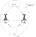
- FIG. 1 is an exemplary architecture of a wireless communication system 100 provided by an embodiment of the present disclosure.
- the wireless communication system 100 of the present embodiment may include: an electronic device 101, a 4G base station 102, a 5Gbase station 103, and a 5G core network device 104.
- a network accessed by the electronic device 101 may be a 5G non-standalone (NSA) network.
- a control plane signaling may be transmitted through the base station 102.
- User plane data of the electronic device may be transmitted to the core network device NGC104 through the base station 102 and the base station 103 respectively.
- the base station 103 may be communicatively connected to the core network device 104.
- the core network device NGC104 may support a dual connection mode.
- the electronic device 101 specifically may maintains a communicative connection with the base station 102 and the base station 103 at the same time in the dual connection mode, and a data transmission service may be achieved through the network.
- the next generation core network may replace the evolved packet core (EPC).
- EPC evolved packet core
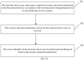
- FIG. 2A is a flowchart of a control method for displaying a service identifier in an electronic device according to an embodiment of the present disclosure.
- the method may be applied in the electronic device shown in FIG. 1 .
- the electronic device may support the eMBB service and the dual connection mode. In the dual connection mode, the electronic device may establish a first communication connection with a first network device and establish a second communication connection with a second network device.
- Each of the first network device and the second network device may be a network device in a 5G NSA network.
- the first network device may be a fourth-generation (4G) base station eNB.
- the second network device may be a 5G base station gNB.
- a core network of the 5G NSA network may be the NGC.
- the first network device may be communicatively connected to the second network device, and the first network device may be communicatively connected to the NGC.
- the control method for displaying the service identifier may include following operations.
- the electronic device may send a query request for resource allocation information to the first network device, in response to the electronic device being detected to be in a downlink data service scenario.
- the electronic device may detect the service scenario of the electronic device.
- the electronic device may send the query request for resource allocation information in response to the electronic device being detected to be in the downlink data service scenario.
- the control plane signaling may be transmitted through the eLTE base station
- the query request for resource allocation information may be sent to the first network device.
- the downlink data service may refer to the electronic device receiving data sent by the eNB or the gNB.
- the resource allocation information sent by the first network device may be received.
- the resource allocation information may include at least one of: a network resource block, a file size, an available downlink bandwidth, etc.
- the first network device may send first resource allocation sub-information corresponding to the first network device to the electronic device.
- the first resource allocation sub-information may include the file size and the available downlink bandwidth corresponding to the first network device.
- the first network device may also forward the query request for resource allocation information to the second network device, and receive second resource allocation sub-information sent by the second network device.
- the second resource allocation sub-information may include a first network resource block of the second network device, a file size of the second network device, and an available downlink bandwidth of the second network device.
- the first network device may send the second resource allocation sub-information to the electronic device.
- the first resource allocation sub-information may carry a first device identifier of the first network device
- the second resource allocation sub-information may carry a second device identifier of the second network device.
- the electronic device may distinguish the first resource allocation sub-information and the second resource allocation sub-information based on the first device identifier and the second device identifier.
- a target service identifier of the electronic device may be determined based on the resource allocation information, and the target service identifier may be displayed.
- the service identifier may be configured to indicate a form of the service data being transmitted under each of various network architectures. For example, in the 4G LTE network, the electronic device may display an icon "VoLTE" on a calling interface in the downlink data service. The identifier "VoLTE" may be configured to indicate that the electronic device may support the downlink data service through the 4G LTE network. In detail, the service data of the downlink data service may be transmitted through the 4G LTE network.
- the service identifier may be at least one of: NR, uRLLC, 4G, 5G, etc., which will not be limited herein.
- the resource allocation information may include the first network resource block of the second network device.
- determining and displaying the target service identifier of the electronic device based on the resource allocation information may include following operations.
- a channel quality indicator of the second network device in response to the first network resource block being less than a first threshold, a channel quality indicator of the second network device may be determined.
- the target service identifier in response to the channel quality indicator being less than a second threshold, the target service identifier may be determined as a first service identifier, and the first service identifier may be displayed on a display interface of the electronic device.
- the target service identifier In response to the channel quality indicator being greater than the second threshold, the target service identifier may be determined as a second service identifier, and the second service identifier may be displayed on the display interface of the electronic device.
- the first service identifier and the second service identifier may indicate transmission form of service data in different network architectures.
- the electronic device may preset the first threshold for the network resource block and the second threshold for the channel quality indicator.
- a threshold may refer to a size of the network resource block, for example, the first threshold may refer to a size of a maximal network resource block.
- the first threshold may be 100, and the second threshold may be 10.
- the channel quality indicator of the second network device may further be determined.
- the above-mentioned first network resource block is sent from the second network device to the first network device, in response to the query request is forwarded from the first network device to the second network device.
- determining the channel quality indicator of the second network device may include following operations.
- a channel parameter and signal strength of the second network device may be acquired.
- the channel quality indicator of the second network device may be determined based on the channel parameter and the signal strength.
- the channel parameter may include at least one of: a transmission rate, a signal-to-noise ratio, channel gain, and a noise power.
- the channel quality indicator may be determined based on the channel parameter and the signal strength.
- the target service identifier may be determined as the first service identifier, the first service identifier may be displayed on the display interface of the electronic device.
- the target service identifier may be determined as the second service identifier, and the second service identifier may be displayed on the display interface of the electronic device.
- the first service identifier and the second service identifier may indicate transmission form of service data in different network architectures.
- the first service identifier may be a 4G icon indicating transmission form of service data in 4G network
- the second service identifier may be a 5G icon indicating transmission form of service data in 5G network.
- FIG. 2B is a presentative view of displaying the first service identifier on the display interface according to an embodiment of the present disclosure.
- the first service identifier may be the "4G" icon.
- FIG. 2C is a presentative view of displaying the second service identifier on the display interface according to an embodiment of the present disclosure.
- the second service identifier may be the "5G" icon.
- the resource allocation information may include a first available downlink bandwidth of the first network device and a second available downlink bandwidth of the second network device, and determining the target service identifier of the electronic device based on the resource allocation information may include following operations.
- the target service identifier of the electronic device may be determined based on the first available downlink bandwidth and the second available downlink bandwidth.
- the electronic device may compare the first available downlink bandwidth with the second available downlink bandwidth after obtaining the first available downlink bandwidth and the second available downlink bandwidth.
- the target service identifier may be determined as the first service identifier, and the first service identifier may be displayed on the display interface of the electronic device.
- the target service identifier may be determined as the second service identifier, and the second service identifier may be displayed on the display interface of the electronic device.
- the first service identifier and the second service identifier may indicate transmission form of service data in different network architectures.
- a service interface of the downlink data service may be determined firstly, correspondence between a pre-configured service interface and a display position of the service identifier may be enquired, and a target display position corresponding to the service interface of the downlink data service may be determined. Subsequently, the service identifier may be displayed at the target display position.
- a preset display position of the service identifier may be variable for various types of service interfaces. For example, on an interface of a calling state, the service identifier may be displayed at an upper left corner of the interface. In another example, in an application interface of another application, the service identifier may be displayed at an upper middle portion of the interface.
- the electronic device may flexibly adjust and adapt the display position of the service identifier on a current service interface for each of various types of service interfaces of the downlink data service, such that the electronic device may have higher flexibility and intelligence for displaying the service identifier.
- the method before the electronic device sends the query request for resource allocation information to the first network device, the method further includes: in response to the electronic device detecting a switch-on event, performing a switch-on registration process, receiving network description information of the 5G NSA network sent from the first network device, and determining a set of service identifiers of the electronic device based on the network description information, and the set of service identifiers may include the target service identifier.
- the network description information may include at least a type and a capability of the NGC network.
- a service identifier set may include following identifiers: 4G VoLTE, VoLTE, and VoNR.
- the 4G VoLTE may be configured to indicate that the downlink data service is supported by an EPC in the 5G NSA system.
- the VoLTE may be configured to indicate that the downlink data service is supported by the NGC and 4G access network in the 5G NSA system cooperatively (specifically, the data may be transmitted from the 4G access network to the core network NPC, or from a 5G access network to the 4G access network and further to the core network NPC).
- the VoNR may be configured to indicate that the downlink data service is supported by the NGC in the 5G NSA system.
- the network side may determine a type of the base station that the electronic device accesses, and a cell at which the electronic device currently resides, i.e. the network side may determine that the network accessed by the electronic device is the 5G NSA network. Subsequently, the network side may send a type and a capability of a core network device of the network to the electronic device.
- the type may include EPC and/or NGC, and the capability may include whether an IMS voice service is supported.
- the service identifier set may include correspondence between the network description information and the service identifier of the downlink data service.
- the electronic device may complete configuration of the service identifier of the downlink data service quickly during the switch-on registration process.
- the service identifier in response to an accessed service operator remaining unchanged, the service identifier may be displayed based on the pre-configured service identifier directly, so as to improve an efficiency and accuracy of the electronic device displaying the service identifier.
- the electronic device in response to the electronic device being detected to be in the downlink data service scenario, may send the query request for resource allocation information to the first network device, receive the resource allocation information sent by the first network device, determine and display the target service identifier of the electronic device based on the resource allocation information.
- the form for transmitting the service data may be selected flexibly based on the resource allocation information of the network device, such that the efficiency and stability of data transmission may be improved, and the actual communication status of the electronic device may be displayed accurately, intuitively and comprehensively, improving comprehensiveness and accuracy of the electronic device displaying information.
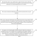
- FIG. 3 is a flowchart of a control method for displaying a service identifier in an electronic device according to an embodiment of the present disclosure.
- the method may be applied in the electronic device shown in FIG. 1 .
- the electronic device may support the eMBB service and the dual connection mode. In the dual connection mode, the electronic device may establish a first communication connection with a first network device and establish a second communication connection with a second network device.
- Each of the first network device and the second network device may be a network device in a 5G NSA network.
- the first network device may be a fourth-generation (4G) base station eNB.
- the second network device may be a 5G base station gNB.
- a core network of the 5G NSA network may be the NGC.
- the first network device may be communicatively connected to the second network device, and the first network device may be communicatively connected to the NGC.
- the present control method for displaying the service identifier may include following operations.
- the electronic device may send the query request for resource allocation information to the first network device.
- the resource allocation information sent by the first network device may be received.
- the resource allocation information may include the first network resource block of the second network device.
- the channel quality indicator of the second network device may be determined.
- the target service identifier in response to the channel quality indicator being less than the second threshold, the target service identifier may be determined as the first service identifier, and the first service identifier may be displayed on the display interface of the electronic device.
- the target service identifier in response to the channel quality indicator being greater than the second threshold, the target service identifier may be determined as the second service identifier, and the second service identifier may be displayed on the display interface of the electronic device.
- the first service identifier and the second service identifier may indicate transmission form of service data in different network architectures.
- the electronic device in response to the electronic device being detected to be in the downlink data service scenario, may send the query request for resource allocation information to the first network device, and receive the resource allocation information sent by the first network device.
- the resource allocation information may include the first network resource block of the second network device.
- the electronic device may determine the channel quality indicator of the second network device.
- the target service identifier may be determined as the first service identifier, and the first service identifier may be displayed on the display interface of the electronic device.
- the target service identifier may be determined as the second service identifier, and the second service identifier may be displayed on the display interface of the electronic device.
- the first service identifier and the second service identifier may indicate transmission form of service data in different network architectures. In this way, as the electronic device maintains the dual connection mode, the form for transmitting the service data may be selected flexibly based on the resource allocation information of the network device, the efficiency and stability of data transmission may be improved, and the actual communication status of the electronic device may be displayed accurately, intuitively and comprehensively, such that comprehensiveness and accuracy of the electronic device displaying information may be improved.
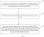
- FIG. 4 is a flowchart of a control method for displaying a service identifier according to an embodiment of the present disclosure.
- the method may be applied in the electronic device.
- the electronic device may support the eMBB service and the dual connection mode.
- the electronic device may establish a first communication connection with a first network device and establish a second communication connection with a second network device.
- Each of the first network device and the second network device may be a network device in a 5G NSA network.
- the first network device may be a fourth-generation (4G) base station eNB.
- the second network device may be a 5G base station gNB.
- a core network of the 5G NSA network may be the NGC.
- the first network device may be communicatively connected to the second network device, and the first network device may be communicatively connected to the NGC.
- the control method for displaying the service identifier may include following operations.
- the electronic device may send the query request for resource allocation information to the first network device.
- the resource allocation information sent by the first network device may be received.
- the resource allocation information may include the first available downlink bandwidth of the first network device and the second available downlink bandwidth of the second network device.
- the target service identifier of the electronic device may be determined and displayed based on the first available downlink bandwidth and the second available downlink bandwidth.
- the electronic device in response to the electronic device being detected to be in the downlink data service scenario, may send the query request for resource allocation information to the first network device, and receive the resource allocation information sent by the first network device.
- the resource allocation information may include the first available downlink bandwidth of the first network device and the second available downlink bandwidth of the second network device.
- the electronic device may determine and display the target service identifier of the electronic device based on the first available downlink bandwidth and the second available downlink bandwidth.
- the electronic device maintains the dual connection mode, and therefore, the electronic device may flexibly select the form for transmitting the service data based on the resource allocation information of the network device, improving the efficiency and stability of data transmission, and the actual communication status of the electronic device may be shown accurately, intuitively and comprehensively, improving the comprehensiveness and accuracy of information displayed by electronic device.
- the electronic device may flexibly select the form for transmitting service data based on the channel quality, thereby improving the efficiency and stability of data transmission.
- FIG. 5 is a structural schematic view of an electronic device according to an embodiment of the present disclosure.
- the electronic device may support the eMBB service and the dual connection mode.
- the electronic device may establish a first communication connection with a first network device and establish a second communication connection with a second network device.
- Each of the first network device and the second network device may be a network device in a 5G NSA network.
- the first network device may be a fourth-generation (4G) base station eNB.
- the second network device may be a 5G base station gNB.
- the 5G NSA network may be the NGC.
- the first network device may be communicatively connected to the second network device, and the first network device may be communicatively connected to the NGC.
- the electronic device 500 may include an application processor 510, a non-transitory memory 520, a communication interface 530, and one or more programs 521.
- the one or more programs 521 may be stored in the non-transitory memory 520 and may be configured to be processed by the application processor 510.
- the one or more programs 521 may include instructions for performing following operations.
- the electronic device may send the query request for resource allocation information to the first network device.
- the resource allocation information sent by the first network device may be received.
- the target service identifier of the electronic device may be determined based on the resource allocation information, and the target service identifier may be displayed.
- the electronic device in response to the electronic device being detected to be in the downlink data service scenario, may send the query request for resource allocation information to the first network device, receive the resource allocation information sent by the first network device, determine the target service identifier of the electronic device based on the resource allocation information, and display the target service identifier.
- the electronic device may select the corresponding service identifier based on the resource allocation information of the network device of the access network, such as displaying the 4G icon or the 5G icon, such that the actual data status of the electronic device in the service process may be displayed accurately, intuitively and comprehensively, improving the comprehensiveness and accuracy of information displayed by the electronic device.
- the programs may include instructions for performing following operations.
- the channel quality indicator of the second network device may be determined.
- the target service identifier may be determined as the first service identifier, and the first service identifier may be displayed on the display interface of the electronic device.
- the target service identifier may be determined as the second service identifier, and the second service identifier may be displayed on the display interface of the electronic device.
- the first service identifier and the second service identifier may indicate transmission form of service data in different network architectures.
- instructions in the programs may be configured to perform following operations.
- the channel parameter and signal strength of the second network device may be acquired.
- the channel quality indicator of the second network device may be determined based on the channel parameter and the signal strength.
- the first service identifier may be the 4G icon indicating transmission form of service data in 4G network
- the second service identifier may be the 5G icon indicating transmission form of service data in 5G network.
- the channel parameter may include at least one of: the transmission rate, the signal-to-noise ratio, the channel gain, and the noise power.
- the first network resource block is sent from the second network device to the first network device, in response to the query request is forwarded from the first network device to the second network device.
- the resource allocation information may include the first available downlink bandwidth of the first network device and the second available downlink bandwidth of the second network device. While determining the target service identifier of the electronic device based on the resource allocation information, the program may include instructions for performing operations of: determining the target service identifier of the electronic device based on the first available downlink bandwidth and the second available downlink bandwidth.
- a processing unit before sending query request for resource allocation information to the first network device, a processing unit may further be configured to perform following operations.
- the switch-on registration process may be executed in response to the switch-on event being detected.
- the network description information of the 5G NSA network sent from the first network device may be received, and the network description information may include at least the type and the capability of the NGC network.
- the target service identifier of the electronic device may be determined based on the network description information.
- the electronic device may include corresponding hardware structures and/or software modules for performing each function.
- the present disclosure may be implemented in the form of hardware or a combination of hardware and computer software. Whether a certain function is achieved by hardware or by computer software-driven hardware may be determined depending on a specific application and a design constraint of the technical solution. Professionals may use different methods for each specific application to implement the described functions, but such implementation should not be considered beyond the scope of the present disclosure.
- the embodiments of the present disclosure may divide the electronic device into functional units based on the above-mentioned examples of the method.
- the electronic device may be divided to obtain each functional unit corresponding to each function, or two or more functions may be integrated into one processing unit.
- the above-mentioned integrated unit may be achieved in the form of hardware or software functional unit. It should be noted that the division into units in the embodiments of the present disclosure is exemplary, and is only a type of logical function division. There may be other division methods in actual implementations.
- FIG. 6 is a block diagram of the functional unit composition of an apparatus 600 for controlling the display of the service identifier involved in the embodiments of the present disclosure.
- the apparatus 600 for controlling the display of the service identifier may be applied in an electronic device.
- the electronic device may support the eMBB service and the dual connection mode. In the dual connection mode, the electronic device may establish a first communication connection with a first network device and establish a second communication connection with a second network device.
- Each of the first network device and the second network device may be a network device in a 5G NSA network.
- the first network device may be a fourth-generation (4G) base station eNB.
- the second network device may be a 5G base station gNB.
- a core network of the 5G NSA network may be the NGC.
- the first network device may be communicatively connected to the second network device, and the first network device may be communicatively connected to the NGC.
- the apparatus 600 for controlling the display of the service identifier may include a sending unit 601, a receiving unit 602, and a processing unit 603.
- the sending unit 601 may be configured to send the query request for resource allocation information to the first network device in response to the electronic device being detected to be in the downlink data service scenario.
- the receiving unit 602 may be configured to receive the resource allocation information sent by the first network device.
- the processing unit 603 may be configured to determine and display the target service identifier of the electronic device based on the resource allocation information.
- the electronic device in response to the electronic device being detected to be in the downlink data service scenario, may send the query request for resource allocation information to the first network device, receive the resource allocation information sent by the first network device, determine and display the target service identifier of the electronic device based on the resource allocation information.
- the electronic device may select the corresponding service identifier based on the resource allocation information of the network device of the access network, such as displaying the 4G icon or the 5G icon, such that the actual data status of the electronic device in the service process may be displayed accurately, intuitively and comprehensively, improving the comprehensiveness and accuracy of information displayed by the electronic device.
- the resource allocation information may include the first network resource block of the second network device. While determining and displaying the target service identifier of the electronic device based on the resource allocation information, the processing unit 603 may specifically be configured to perform following operations.
- the channel quality indicator of the second network device may be determined.
- the target service identifier may be determined as the first service identifier, and the first service identifier may be displayed on the display interface of the electronic device.
- the target service identifier may be determined as the second service identifier, and the second service identifier may be displayed on the display interface of the electronic device.
- the first service identifier and the second service identifier may indicate transmission form of service data in different network architectures.
- the processing unit 603 may specifically be configured to perform following operations.
- the channel parameter and the signal strength of the second network device may be acquired.
- the channel quality indicator of the second network device may be determined based on the channel parameter and the signal strength.
- the first service identifier may be the 4G icon indicating transmission form of service data in 4G network
- the second service identifier may be the 5G icon indicating transmission form of service data in 5G network.
- the first network resource block is sent from the second network device to the first network device, in response to the query request is forwarded from the first network device to the second network device.
- the resource allocation information may include the first available downlink bandwidth of the first network device and the second available downlink bandwidth of the second network device. While determining the target service identifier of the electronic device based on the resource allocation information, the processing unit 603 may specifically be configured to: determine target the service identifier of the electronic device based on the first available downlink bandwidth and the second available downlink bandwidth.
- the embodiments of the present disclosure may further provide a non-transitory computer storage medium.
- the non-transitory computer storage medium may store a computer program for exchange electronic data.
- the computer program enables a computer to execute a part or all of the operations of any method as described in the above method embodiments, and the computer may include an electronic device.
- the embodiments of the present disclosure also provide a computer program product.
- the computer program product may include a non-transitory computer-readable storage medium storing a computer program.
- the computer program is operable to enable a computer to execute a part or all of the operations of any method as described in the above method embodiments.
- the computer program product may be a software installation package, and the computer may include an electronic product.
- the disclosed apparatus may be implemented by other means.
- the apparatus embodiments described above are merely illustrative.
- the above-mentioned division of the units is only a type of logical function division, and there may be other types of division in actual implementation, for example, multiple units or components may be combined or integrated into another system, or some features may be omitted or not implemented.
- the described or discussed mutual coupling or direct coupling or communicative connection may be achieved through some interfaces, indirect coupling or communicative connection.
- the connection and coupling of devices or units may be in electrical or other forms.
- the units described above as separate components may or may not be physically separated, and the components displayed as units may or may not be physical units. That is, they may be located in one place, or they may be distributed on multiple network units. Some or all of the units may be selected according to actual needs to achieve the objectives of the solutions of the embodiments.
- various functional units in the various embodiments of the present disclosure may be integrated into one processing unit.
- each unit may exist alone physically.
- two or more units may be integrated into one unit.
- the above-mentioned integrated unit may be achieved in the form of hardware or software functional unit.
- the unit When the above integrated unit is implemented in the form of a software functional unit and sold or used as an independent product, the unit may be stored in a non-transitory computer readable memory. In this way, the essence of the technical solution of the present disclosure, or the part of the technical solution of the present disclosure that contributes to the art, or all or a part of the technical solution of the present disclosure may be achieved in the form of a software product.
- the computer software product may be stored in a non-transitory memory and include a number of instructions to enable a computer device (which may be a personal computer, a server, or a network device, etc.) to perform all or a part of the operations of the above-mentioned methods of the various embodiments of the present disclosure.
- the above-mentioned non-transitory memory may include: a universal serial bus disk, a read-only memory (ROM), a random access memory (RAM), a mobile hard drive, a magnetic disk, or an optical disk and other media that can store program codes.
- ROM read-only memory
- RAM random access memory
- mobile hard drive a magnetic disk
- optical disk an optical disk and other media that can store program codes.
- the program may be stored in the computer-readable non-transitory memory, and the non-transitory memory may include: a flash disk, the Read-only memory (ROM), the random access memory (RAM), the magnetic disk or the optical disk, etc.
Description
- The present disclosure relates to the field of electronic devices, and in particular to a control method for displaying a service identifier in an electronic device, an electronic device, and a computer-readable storage medium.
- With the development of the mobile communication technology, users have an increasing demand for communicating using electronic devices such as mobile phones. In the art, while electronic devices are transmitting data, data plane services may be transmitted through a data network, such as the 4th Generation (4G) long-term evolution (LTE) network, whereas telephone service data may still be transmitted through a traditional circuit domain network, such as the 2nd Generation (2G) and the 3rd Generation (3G) networks. The electronic device may display a service identifier on a relevant interface of a local end to indicate a current communication status of the electronic device. With respect to an IMS call service of an IP multimedia subsystem, a display scheme for a service identifier of a downlink data service in a 5G NSA communication system is still not available in the art.
- A method for prioritizing frequency bands of a communication network and a communication terminal are disclosed in
CN 103209460 A . - A control method for displaying a service identifier in an electronic device, an electronic device, and a computer-readable storage medium are provided as set out in the appended set of claims.
- According to the present disclosure, the electronic device may send a query request for resource allocation information to the first network device, in response to the electronic device being detected to be in a downlink data service scenario; may receive the resource allocation information from the first network device; and may determine and display a target service identifier of the electronic device based on the resource allocation information. In this way, an actual communication status of the electronic device may be displayed accurately, intuitively and comprehensively, improving comprehensiveness and accuracy of the electronic device displaying information.
- In order to clearly describe technical solutions in the embodiments of the present application or in the prior art, accompanying drawings for the description of the embodiments or the prior art will be introduced in brief. Obviously, the drawings in the following description are only some embodiments of the present disclosure. Any ordinary skilled in the art may obtain other drawings based on the following drawings without creative work.
-
FIG. 1 is an exemplary architecture of a wireless communication system according to an embodiment of the present disclosure. -
FIG. 2A is a flowchart of a control method for displaying a service identifier in an electronic device according to an embodiment of the present disclosure. -
FIG. 2B is a presentative view of displaying a first service identifier on a display interface according to an embodiment of the present disclosure. -
FIG. 2C is a presentative view of displaying a second service identifier on a display interface according to an embodiment of the present disclosure. -
FIG. 3 is a flowchart of another control method for displaying a service identifier in an electronic device according to an embodiment of the present disclosure. -
FIG. 4 is a flowchart of another control method for displaying a service identifier in an electronic device according to an embodiment of the present disclosure. -
FIG. 5 is structural schematic view of an electronic device according to an embodiment of the present disclosure. -
FIG. 6 is a block diagram of functional units of an apparatus for controlling display of a service identifier according to an embodiment of the present disclosure. - In order to enable the skilled person in the art to better understand technical solutions of the present disclosure, the technical solutions of the embodiments of the present disclosure will be described clearly and completely in combination with the accompanying drawings Obviously, the described embodiments are only a part of, but not all of, the embodiments of the present disclosure. Based on the embodiments in the present disclosure, all other embodiments may be obtained by an ordinary skilled person in the art without creative work, and shall fall within the scope of the present disclosure.
- Terms "first", "second", and the like in the description and claims of the present disclosure and in the above-mentioned drawings are used to distinguish different objects, but not to describe a specific order. Furthermore, terms "including", "having" and any variations thereof are intended to suggest non-exclusive inclusion. For example, a process, a method, a system, a product, or a device including a series of operations or units are not limited to the listed operations or units, but alternatively also includes operations or units that are not listed, or also includes other operations or units inherently included in the process, in the method, in the product or in the device.
- An "embodiment" mentioned in the present disclosure may refer to a particular feature, a structure, or a property described in connection with the embodiment being included in at least one embodiment of the present disclosure. The term occurring in various sections of the specification may not refer to a same embodiment, or an embodiment that is independent from, alternative to, or mutually exclusive with other embodiments. Skilled person in the art shall understand that the embodiments described herein may be combined with other embodiments.
- The electronic device involved in the embodiments of the present disclosure may be an electronic device capable of transmitting data. The electronic device may include various devices with wireless communication functions, such as a handheld device, a vehicle-mounted device, a wearable device, a computing device, or a wireless modem, and user equipment (UE) in various forms, a mobile station (MS), a terminal device, and so on. The embodiments of the present disclosure will be described in detail below.
- The technical solutions of the embodiments of the present disclosure may be applied to various communication systems. The communication systems may include, but are not limited to, a Global System of Mobile communication (GSM) system, a Code Division Multiple Access (CDMA) system, a Wideband Code Division Multiple Access (WCDMA) system, a General Packet Radio Service (GPRS), a Long Term Evolution (LTE) system, a LTE Frequency Division Duplex (FDD) system, a LTE Time Division Duplex (TDD), a Universal Mobile Telecommunication System (UMTS), a Worldwide Interoperability for Microwave Access (WiMAX) communication system or a 5G new radio (NR) and so on. In detail, the technical solutions in the embodiments of the present disclosure may be applied to eMBB services under the Option 7a architecture or ultra reliable low latency communications (URLLC).
- As shown in
FIG. 1, FIG. 1 is an exemplary architecture of awireless communication system 100 provided by an embodiment of the present disclosure. Thewireless communication system 100 of the present embodiment may include: anelectronic device 101, a4G base station 102, a5Gbase station 103, and a 5Gcore network device 104. A network accessed by theelectronic device 101 may be a 5G non-standalone (NSA) network. A control plane signaling may be transmitted through thebase station 102. User plane data of the electronic device may be transmitted to the core network device NGC104 through thebase station 102 and thebase station 103 respectively. Thebase station 103 may be communicatively connected to thecore network device 104. The core network device NGC104 may support a dual connection mode. Theelectronic device 101 specifically may maintains a communicative connection with thebase station 102 and thebase station 103 at the same time in the dual connection mode, and a data transmission service may be achieved through the network. In addition, in the network, the next generation core network (NGC) may replace the evolved packet core (EPC). In this way, a risk of a core network signaling being overloaded may be solved, and the electronic device may achieve voice call services, such as an eMBB service, through the network. - As shown in
FIG. 2A, FIG. 2A is a flowchart of a control method for displaying a service identifier in an electronic device according to an embodiment of the present disclosure. The method may be applied in the electronic device shown inFIG. 1 . The electronic device may support the eMBB service and the dual connection mode. In the dual connection mode, the electronic device may establish a first communication connection with a first network device and establish a second communication connection with a second network device. Each of the first network device and the second network device may be a network device in a 5G NSA network. The first network device may be a fourth-generation (4G) base station eNB. The second network device may be a 5G base station gNB. A core network of the 5G NSA network may be the NGC. The first network device may be communicatively connected to the second network device, and the first network device may be communicatively connected to the NGC. As shown inFIG. 2A , the control method for displaying the service identifier may include following operations. - In an
operation 201, the electronic device may send a query request for resource allocation information to the first network device, in response to the electronic device being detected to be in a downlink data service scenario. - In the present embodiment, the electronic device may detect the service scenario of the electronic device. The electronic device may send the query request for resource allocation information in response to the electronic device being detected to be in the downlink data service scenario. Considering that the control plane signaling may be transmitted through the eLTE base station, the query request for resource allocation information may be sent to the first network device. The downlink data service may refer to the electronic device receiving data sent by the eNB or the gNB.
- In an
operation 202, the resource allocation information sent by the first network device may be received. - The resource allocation information may include at least one of: a network resource block, a file size, an available downlink bandwidth, etc. In the present embodiment, after receiving the query request for resource allocation information, the first network device may send first resource allocation sub-information corresponding to the first network device to the electronic device. The first resource allocation sub-information may include the file size and the available downlink bandwidth corresponding to the first network device. The first network device may also forward the query request for resource allocation information to the second network device, and receive second resource allocation sub-information sent by the second network device. The second resource allocation sub-information may include a first network resource block of the second network device, a file size of the second network device, and an available downlink bandwidth of the second network device. Subsequently, the first network device may send the second resource allocation sub-information to the electronic device. The first resource allocation sub-information may carry a first device identifier of the first network device, and the second resource allocation sub-information may carry a second device identifier of the second network device. In this way, the electronic device may distinguish the first resource allocation sub-information and the second resource allocation sub-information based on the first device identifier and the second device identifier.
- In an
operation 203, a target service identifier of the electronic device may be determined based on the resource allocation information, and the target service identifier may be displayed. - The service identifier may be configured to indicate a form of the service data being transmitted under each of various network architectures. For example, in the 4G LTE network, the electronic device may display an icon "VoLTE" on a calling interface in the downlink data service. The identifier "VoLTE" may be configured to indicate that the electronic device may support the downlink data service through the 4G LTE network. In detail, the service data of the downlink data service may be transmitted through the 4G LTE network.
- The service identifier may be at least one of: NR, uRLLC, 4G, 5G, etc., which will not be limited herein.
- Alternatively, the resource allocation information may include the first network resource block of the second network device. In the
operation 103, determining and displaying the target service identifier of the electronic device based on the resource allocation information, may include following operations. - In an operation 31, in response to the first network resource block being less than a first threshold, a channel quality indicator of the second network device may be determined.
- In an operation 32, in response to the channel quality indicator being less than a second threshold, the target service identifier may be determined as a first service identifier, and the first service identifier may be displayed on a display interface of the electronic device. In response to the channel quality indicator being greater than the second threshold, the target service identifier may be determined as a second service identifier, and the second service identifier may be displayed on the display interface of the electronic device. The first service identifier and the second service identifier may indicate transmission form of service data in different network architectures.
- The electronic device may preset the first threshold for the network resource block and the second threshold for the channel quality indicator. A threshold may refer to a size of the network resource block, for example, the first threshold may refer to a size of a maximal network resource block. For example, the first threshold may be 100, and the second threshold may be 10. After the first network resource block is determined, it may be determined whether the first network resource block is less than the first threshold. In response to the first network resource block being less than the first threshold, the channel quality indicator of the second network device may further be determined.
- Alternatively, the above-mentioned first network resource block is sent from the second network device to the first network device, in response to the query request is forwarded from the first network device to the second network device.
- Alternatively, determining the channel quality indicator of the second network device may include following operations.
- In an operation A1, a channel parameter and signal strength of the second network device may be acquired.
- In an operation A2, the channel quality indicator of the second network device may be determined based on the channel parameter and the signal strength.
- The channel parameter may include at least one of: a transmission rate, a signal-to-noise ratio, channel gain, and a noise power. In the present embodiment, the channel quality indicator may be determined based on the channel parameter and the signal strength. In response to the channel quality indicator being less than the second threshold, the target service identifier may be determined as the first service identifier, the first service identifier may be displayed on the display interface of the electronic device. In response to the channel quality indicator being greater than the second threshold, the target service identifier may be determined as the second service identifier, and the second service identifier may be displayed on the display interface of the electronic device. The first service identifier and the second service identifier may indicate transmission form of service data in different network architectures.
- Alternatively, the first service identifier may be a 4G icon indicating transmission form of service data in 4G network, and the second service identifier may be a 5G icon indicating transmission form of service data in 5G network.
- As shown in
FIGS. 2B to 2C ,FIG. 2B is a presentative view of displaying the first service identifier on the display interface according to an embodiment of the present disclosure. As shown inFIG. 2B , the first service identifier may be the "4G" icon.FIG. 2C is a presentative view of displaying the second service identifier on the display interface according to an embodiment of the present disclosure. As shown inFIG. 2C , the second service identifier may be the "5G" icon. - Alternatively, the resource allocation information may include a first available downlink bandwidth of the first network device and a second available downlink bandwidth of the second network device, and determining the target service identifier of the electronic device based on the resource allocation information may include following operations.
- The target service identifier of the electronic device may be determined based on the first available downlink bandwidth and the second available downlink bandwidth.
- The electronic device may compare the first available downlink bandwidth with the second available downlink bandwidth after obtaining the first available downlink bandwidth and the second available downlink bandwidth. In response to the first available downlink bandwidth being greater than the second available downlink bandwidth, the target service identifier may be determined as the first service identifier, and the first service identifier may be displayed on the display interface of the electronic device. In response to the first available downlink bandwidth being less than the second available downlink bandwidth, the target service identifier may be determined as the second service identifier, and the second service identifier may be displayed on the display interface of the electronic device. The first service identifier and the second service identifier may indicate transmission form of service data in different network architectures.
- In order to display the service identifier on the display interface of the electronic device, a service interface of the downlink data service may be determined firstly, correspondence between a pre-configured service interface and a display position of the service identifier may be enquired, and a target display position corresponding to the service interface of the downlink data service may be determined. Subsequently, the service identifier may be displayed at the target display position. In a specific implementation, a preset display position of the service identifier may be variable for various types of service interfaces. For example, on an interface of a calling state, the service identifier may be displayed at an upper left corner of the interface. In another example, in an application interface of another application, the service identifier may be displayed at an upper middle portion of the interface. In this way, the electronic device may flexibly adjust and adapt the display position of the service identifier on a current service interface for each of various types of service interfaces of the downlink data service, such that the electronic device may have higher flexibility and intelligence for displaying the service identifier.
- Alternatively, in the present embodiment, before the electronic device sends the query request for resource allocation information to the first network device, the method further includes: in response to the electronic device detecting a switch-on event, performing a switch-on registration process, receiving network description information of the 5G NSA network sent from the first network device, and determining a set of service identifiers of the electronic device based on the network description information, and the set of service identifiers may include the target service identifier. The network description information may include at least a type and a capability of the NGC network.
- A service identifier set may include following identifiers: 4G VoLTE, VoLTE, and VoNR. The 4G VoLTE may be configured to indicate that the downlink data service is supported by an EPC in the 5G NSA system. The VoLTE may be configured to indicate that the downlink data service is supported by the NGC and 4G access network in the 5G NSA system cooperatively (specifically, the data may be transmitted from the 4G access network to the core network NPC, or from a 5G access network to the 4G access network and further to the core network NPC). The VoNR may be configured to indicate that the downlink data service is supported by the NGC in the 5G NSA system.
- In a specific implementation, while the electronic device is performing the switch-on registration process, the network side may determine a type of the base station that the electronic device accesses, and a cell at which the electronic device currently resides, i.e. the network side may determine that the network accessed by the electronic device is the 5G NSA network. Subsequently, the network side may send a type and a capability of a core network device of the network to the electronic device. The type may include EPC and/or NGC, and the capability may include whether an IMS voice service is supported. In addition, the service identifier set may include correspondence between the network description information and the service identifier of the downlink data service. In this way, the electronic device may complete configuration of the service identifier of the downlink data service quickly during the switch-on registration process. In this way, in a subsequent process of enabling the downlink data service, in response to an accessed service operator remaining unchanged, the service identifier may be displayed based on the pre-configured service identifier directly, so as to improve an efficiency and accuracy of the electronic device displaying the service identifier.
- It may be seen that, in the present embodiment, in response to the electronic device being detected to be in the downlink data service scenario, the electronic device may send the query request for resource allocation information to the first network device, receive the resource allocation information sent by the first network device, determine and display the target service identifier of the electronic device based on the resource allocation information. In this way, as the electronic device is maintained in the dual connection mode, the form for transmitting the service data may be selected flexibly based on the resource allocation information of the network device, such that the efficiency and stability of data transmission may be improved, and the actual communication status of the electronic device may be displayed accurately, intuitively and comprehensively, improving comprehensiveness and accuracy of the electronic device displaying information.
- In conformity with the embodiment shown in
FIG. 2A , as shown inFIG. 3, FIG. 3 is a flowchart of a control method for displaying a service identifier in an electronic device according to an embodiment of the present disclosure. The method may be applied in the electronic device shown inFIG. 1 . The electronic device may support the eMBB service and the dual connection mode. In the dual connection mode, the electronic device may establish a first communication connection with a first network device and establish a second communication connection with a second network device. Each of the first network device and the second network device may be a network device in a 5G NSA network. The first network device may be a fourth-generation (4G) base station eNB. The second network device may be a 5G base station gNB. A core network of the 5G NSA network may be the NGC. The first network device may be communicatively connected to the second network device, and the first network device may be communicatively connected to the NGC. As shown inFIG. 3 , the present control method for displaying the service identifier may include following operations. - In an
operation 301, in response to the electronic device being detected to be in the downlink data service scenario, the electronic device may send the query request for resource allocation information to the first network device. - In an
operation 302, the resource allocation information sent by the first network device may be received. - In an
operation 303, the resource allocation information may include the first network resource block of the second network device. In response to the first network resource block being less than the first threshold, the channel quality indicator of the second network device may be determined. - In an
operation 304, in response to the channel quality indicator being less than the second threshold, the target service identifier may be determined as the first service identifier, and the first service identifier may be displayed on the display interface of the electronic device. In response to the channel quality indicator being greater than the second threshold, the target service identifier may be determined as the second service identifier, and the second service identifier may be displayed on the display interface of the electronic device. The first service identifier and the second service identifier may indicate transmission form of service data in different network architectures. - It may be seen that, in the present embodiment, in response to the electronic device being detected to be in the downlink data service scenario, the electronic device may send the query request for resource allocation information to the first network device, and receive the resource allocation information sent by the first network device. The resource allocation information may include the first network resource block of the second network device. In response to the first network resource block being less than the first threshold, the electronic device may determine the channel quality indicator of the second network device. In response to the channel quality indicator being less than the second threshold, the target service identifier may be determined as the first service identifier, and the first service identifier may be displayed on the display interface of the electronic device. In response to the channel quality indicator being greater than the second threshold, the target service identifier may be determined as the second service identifier, and the second service identifier may be displayed on the display interface of the electronic device. The first service identifier and the second service identifier may indicate transmission form of service data in different network architectures. In this way, as the electronic device maintains the dual connection mode, the form for transmitting the service data may be selected flexibly based on the resource allocation information of the network device, the efficiency and stability of data transmission may be improved, and the actual communication status of the electronic device may be displayed accurately, intuitively and comprehensively, such that comprehensiveness and accuracy of the electronic device displaying information may be improved.
- In conformity with the embodiment shown in
FIG. 2A , as shown inFIG. 4, FIG. 4 is a flowchart of a control method for displaying a service identifier according to an embodiment of the present disclosure. The method may be applied in the electronic device. The electronic device may support the eMBB service and the dual connection mode. In the dual connection mode, the electronic device may establish a first communication connection with a first network device and establish a second communication connection with a second network device. Each of the first network device and the second network device may be a network device in a 5G NSA network. The first network device may be a fourth-generation (4G) base station eNB. The second network device may be a 5G base station gNB. A core network of the 5G NSA network may be the NGC. The first network device may be communicatively connected to the second network device, and the first network device may be communicatively connected to the NGC. As shown inFIG. 4 , the control method for displaying the service identifier may include following operations. - In an
operation 401, in response to the electronic device being detected to be in the downlink data service scenario, the electronic device may send the query request for resource allocation information to the first network device. - In an
operation 402, the resource allocation information sent by the first network device may be received. - In an
operation 403, the resource allocation information may include the first available downlink bandwidth of the first network device and the second available downlink bandwidth of the second network device. The target service identifier of the electronic device may be determined and displayed based on the first available downlink bandwidth and the second available downlink bandwidth. - It can be seen that, in the present embodiment, in response to the electronic device being detected to be in the downlink data service scenario, the electronic device may send the query request for resource allocation information to the first network device, and receive the resource allocation information sent by the first network device. The resource allocation information may include the first available downlink bandwidth of the first network device and the second available downlink bandwidth of the second network device. The electronic device may determine and display the target service identifier of the electronic device based on the first available downlink bandwidth and the second available downlink bandwidth. In this way, the electronic device maintains the dual connection mode, and therefore, the electronic device may flexibly select the form for transmitting the service data based on the resource allocation information of the network device, improving the efficiency and stability of data transmission, and the actual communication status of the electronic device may be shown accurately, intuitively and comprehensively, improving the comprehensiveness and accuracy of information displayed by electronic device.
- In addition, as the electronic device maintains the dual connection mode, the electronic device may flexibly select the form for transmitting service data based on the channel quality, thereby improving the efficiency and stability of data transmission.
- In conformity with the embodiments shown in
FIGS. 2A ,3 , and4 , as shown inFIG. 5, FIG. 5 is a structural schematic view of an electronic device according to an embodiment of the present disclosure. As shown in the figure, the embodiment may be applied in theelectronic device 500. The electronic device may support the eMBB service and the dual connection mode. In the dual connection mode, the electronic device may establish a first communication connection with a first network device and establish a second communication connection with a second network device. Each of the first network device and the second network device may be a network device in a 5G NSA network. The first network device may be a fourth-generation (4G) base station eNB. The second network device may be a 5G base station gNB. A core network of the - 5G NSA network may be the NGC. The first network device may be communicatively connected to the second network device, and the first network device may be communicatively connected to the NGC. The
electronic device 500 may include anapplication processor 510, anon-transitory memory 520, acommunication interface 530, and one ormore programs 521. The one ormore programs 521 may be stored in thenon-transitory memory 520 and may be configured to be processed by theapplication processor 510. The one ormore programs 521 may include instructions for performing following operations. - In response to the electronic device being detected to be in the downlink data service scenario, the electronic device may send the query request for resource allocation information to the first network device.
- The resource allocation information sent by the first network device may be received.
- The target service identifier of the electronic device may be determined based on the resource allocation information, and the target service identifier may be displayed.
- It may be seen that, in the present embodiment, in response to the electronic device being detected to be in the downlink data service scenario, the electronic device may send the query request for resource allocation information to the first network device, receive the resource allocation information sent by the first network device, determine the target service identifier of the electronic device based on the resource allocation information, and display the target service identifier. In the downlink data service scenario, the electronic device may select the corresponding service identifier based on the resource allocation information of the network device of the access network, such as displaying the 4G icon or the 5G icon, such that the actual data status of the electronic device in the service process may be displayed accurately, intuitively and comprehensively, improving the comprehensiveness and accuracy of information displayed by the electronic device.
- In one embodiment, while determining and displaying the target service identifier of the electronic device based on the resource allocation information, the programs may include instructions for performing following operations.
- In response to the first network resource block being less than the first threshold, the channel quality indicator of the second network device may be determined.
- In response to the channel quality indicator being less than the second threshold, the target service identifier may be determined as the first service identifier, and the first service identifier may be displayed on the display interface of the electronic device. In response to the channel quality indicator being greater than the second threshold, the target service identifier may be determined as the second service identifier, and the second service identifier may be displayed on the display interface of the electronic device. The first service identifier and the second service identifier may indicate transmission form of service data in different network architectures.
- In one embodiment, while determining the channel quality indicator of the second network device, instructions in the programs may be configured to perform following operations. The channel parameter and signal strength of the second network device may be acquired.
- The channel quality indicator of the second network device may be determined based on the channel parameter and the signal strength.
- In one embodiment, the first service identifier may be the 4G icon indicating transmission form of service data in 4G network, and the second service identifier may be the 5G icon indicating transmission form of service data in 5G network.
- In one embodiment, the channel parameter may include at least one of: the transmission rate, the signal-to-noise ratio, the channel gain, and the noise power.
- In one embodiment, the first network resource block is sent from the second network device to the first network device, in response to the query request is forwarded from the first network device to the second network device.
- In one embodiment, the resource allocation information may include the first available downlink bandwidth of the first network device and the second available downlink bandwidth of the second network device. While determining the target service identifier of the electronic device based on the resource allocation information, the program may include instructions for performing operations of: determining the target service identifier of the electronic device based on the first available downlink bandwidth and the second available downlink bandwidth.
- In one embodiment, before sending query request for resource allocation information to the first network device, a processing unit may further be configured to perform following operations. The switch-on registration process may be executed in response to the switch-on event being detected.
- The network description information of the 5G NSA network sent from the first network device may be received, and the network description information may include at least the type and the capability of the NGC network.
- The target service identifier of the electronic device may be determined based on the network description information.
- The above description mainly introduces the technical solution of the embodiments of the present disclosure from the perspective of an execution process of the method. It should be understood that in order to implement the above-mentioned functions, the electronic device may include corresponding hardware structures and/or software modules for performing each function. Those skilled in the art should easily realize that in combination with the exemplary units and algorithm operations in the embodiments provided herein, the present disclosure may be implemented in the form of hardware or a combination of hardware and computer software. Whether a certain function is achieved by hardware or by computer software-driven hardware may be determined depending on a specific application and a design constraint of the technical solution. Professionals may use different methods for each specific application to implement the described functions, but such implementation should not be considered beyond the scope of the present disclosure.
- The embodiments of the present disclosure may divide the electronic device into functional units based on the above-mentioned examples of the method. For example, the electronic device may be divided to obtain each functional unit corresponding to each function, or two or more functions may be integrated into one processing unit. The above-mentioned integrated unit may be achieved in the form of hardware or software functional unit. It should be noted that the division into units in the embodiments of the present disclosure is exemplary, and is only a type of logical function division. There may be other division methods in actual implementations.
-
FIG. 6 is a block diagram of the functional unit composition of anapparatus 600 for controlling the display of the service identifier involved in the embodiments of the present disclosure. Theapparatus 600 for controlling the display of the service identifier may be applied in an electronic device. The electronic device may support the eMBB service and the dual connection mode. In the dual connection mode, the electronic device may establish a first communication connection with a first network device and establish a second communication connection with a second network device. Each of the first network device and the second network device may be a network device in a 5G NSA network. The first network device may be a fourth-generation (4G) base station eNB. The second network device may be a 5G base station gNB. A core network of the 5G NSA network may be the NGC. The first network device may be communicatively connected to the second network device, and the first network device may be communicatively connected to the NGC. Theapparatus 600 for controlling the display of the service identifier may include a sendingunit 601, a receivingunit 602, and aprocessing unit 603. - The sending
unit 601 may be configured to send the query request for resource allocation information to the first network device in response to the electronic device being detected to be in the downlink data service scenario. - The receiving
unit 602 may be configured to receive the resource allocation information sent by the first network device. - The
processing unit 603 may be configured to determine and display the target service identifier of the electronic device based on the resource allocation information. - It may be seen that, in the present embodiment, in response to the electronic device being detected to be in the downlink data service scenario, the electronic device may send the query request for resource allocation information to the first network device, receive the resource allocation information sent by the first network device, determine and display the target service identifier of the electronic device based on the resource allocation information. In the downlink data service scenario, the electronic device may select the corresponding service identifier based on the resource allocation information of the network device of the access network, such as displaying the 4G icon or the 5G icon, such that the actual data status of the electronic device in the service process may be displayed accurately, intuitively and comprehensively, improving the comprehensiveness and accuracy of information displayed by the electronic device.
- In one embodiment, the resource allocation information may include the first network resource block of the second network device. While determining and displaying the target service identifier of the electronic device based on the resource allocation information, the
processing unit 603 may specifically be configured to perform following operations. - In response to the first network resource block being less than the first threshold, the channel quality indicator of the second network device may be determined.
- In response to the channel quality indicator being less than the second threshold, the target service identifier may be determined as the first service identifier, and the first service identifier may be displayed on the display interface of the electronic device. In response to the channel quality indicator being greater than the second threshold, the target service identifier may be determined as the second service identifier, and the second service identifier may be displayed on the display interface of the electronic device. The first service identifier and the second service identifier may indicate transmission form of service data in different network architectures.
- In one embodiment, while determining the channel quality indicator of the second network device, the
processing unit 603 may specifically be configured to perform following operations. - The channel parameter and the signal strength of the second network device may be acquired.
- The channel quality indicator of the second network device may be determined based on the channel parameter and the signal strength.
- In one embodiment, the first service identifier may be the 4G icon indicating transmission form of service data in 4G network, and the second service identifier may be the 5G icon indicating transmission form of service data in 5G network.
- In one embodiment, the first network resource block is sent from the second network device to the first network device, in response to the query request is forwarded from the first network device to the second network device.
- In one embodiment, the resource allocation information may include the first available downlink bandwidth of the first network device and the second available downlink bandwidth of the second network device. While determining the target service identifier of the electronic device based on the resource allocation information, the
processing unit 603 may specifically be configured to: determine target the service identifier of the electronic device based on the first available downlink bandwidth and the second available downlink bandwidth. - The embodiments of the present disclosure may further provide a non-transitory computer storage medium. The non-transitory computer storage medium may store a computer program for exchange electronic data. The computer program enables a computer to execute a part or all of the operations of any method as described in the above method embodiments, and the computer may include an electronic device.
- The embodiments of the present disclosure also provide a computer program product. The computer program product may include a non-transitory computer-readable storage medium storing a computer program. The computer program is operable to enable a computer to execute a part or all of the operations of any method as described in the above method embodiments. The computer program product may be a software installation package, and the computer may include an electronic product.
- It should be illustrated that, in order to provide a concise description for the foregoing method embodiments, the embodiments are all expressed as a series of action combinations, but those skilled in the art should know that the present disclosure is not limited by the described sequence of actions, because according to the present disclosure, some operations may be performed in another order or simultaneously. Further, those skilled in the art should also be aware that the embodiments described in the specification are all preferred embodiments, and the involved actions and modules may not be necessary for the present disclosure.
- In the above embodiments, the description of each embodiment has its own emphasis. Parts that are not described in detail in one embodiment may refer to related descriptions in other embodiments.
- In the embodiments provided in the present disclosure, it should be understood that the disclosed apparatus may be implemented by other means. For example, the apparatus embodiments described above are merely illustrative. For example, the above-mentioned division of the units is only a type of logical function division, and there may be other types of division in actual implementation, for example, multiple units or components may be combined or integrated into another system, or some features may be omitted or not implemented. Further, the described or discussed mutual coupling or direct coupling or communicative connection may be achieved through some interfaces, indirect coupling or communicative connection. The connection and coupling of devices or units may be in electrical or other forms.
- The units described above as separate components may or may not be physically separated, and the components displayed as units may or may not be physical units. That is, they may be located in one place, or they may be distributed on multiple network units. Some or all of the units may be selected according to actual needs to achieve the objectives of the solutions of the embodiments.
- In addition, various functional units in the various embodiments of the present disclosure may be integrated into one processing unit. Alternatively, each unit may exist alone physically. Alternatively, two or more units may be integrated into one unit. The above-mentioned integrated unit may be achieved in the form of hardware or software functional unit.
- When the above integrated unit is implemented in the form of a software functional unit and sold or used as an independent product, the unit may be stored in a non-transitory computer readable memory. In this way, the essence of the technical solution of the present disclosure, or the part of the technical solution of the present disclosure that contributes to the art, or all or a part of the technical solution of the present disclosure may be achieved in the form of a software product. The computer software product may be stored in a non-transitory memory and include a number of instructions to enable a computer device (which may be a personal computer, a server, or a network device, etc.) to perform all or a part of the operations of the above-mentioned methods of the various embodiments of the present disclosure. The above-mentioned non-transitory memory may include: a universal serial bus disk, a read-only memory (ROM), a random access memory (RAM), a mobile hard drive, a magnetic disk, or an optical disk and other media that can store program codes.
- Those ordinary skilled in the art should understand that all or a part of the operations in the various methods of the embodiments may be completed by a program instructing relevant hardware. The program may be stored in the computer-readable non-transitory memory, and the non-transitory memory may include: a flash disk, the Read-only memory (ROM), the random access memory (RAM), the magnetic disk or the optical disk, etc.
- The embodiments of the present disclosure are described in detail, and specific examples are used in the specification to illustrate principles and implementation of the present disclosure. The descriptions of the above embodiments are used to facilitate the understanding of the methods and essential concept of the present disclosure. Based on the concept of the present disclosure, any ordinary skilled in the art may perform modification in the specific implementation and the scope of application. In summary, the content of the specification should not be understood as a limitation to the present disclosure.
Claims (9)
- A control method for displaying a service identifier in an electronic device, the electronic device supporting a dual connection mode in which the electronic device is capable of establishing a first communication connection with a first network device, and is capable of establishing a second communication connection with a second network device, each of the first network device and the second network device being a network device in a first fifth generation 5G non-standalone NSA network, the first network device being a fourth generation 4G base station eNB; the second network device being a fifth generation 5G base station gNB; a core network of the first 5G NSA network being a next generation core network NGC, the first network device being in a communication connection with the second network device, and the first network device being in a communication connection with the NGC, the control method comprising:sending (201) a query request for resource allocation information to the first network device, in response to the electronic device being detected to be in a downlink data service scenario;receiving (202) the resource allocation information from the first network device; anddetermining and displaying (203) a target service identifier of the electronic device based on the resource allocation information;wherein the resource allocation information comprises a first network resource block of the second network device; the determining and displaying (203) a target service identifier of the electronic device based on the resource allocation information, comprises:determining (303) a channel quality indicator of the second network device, in response to the first network resource block being less than a first threshold;determining the target service identifier as a first service identifier corresponding to the first network device and displaying (304) the first service identifier on a display interface of the electronic device, in response to the channel quality indicator being less than a second threshold; anddetermining the target service identifier as a second service identifier corresponding to the second network device and displaying the second service identifier on the display interface of the electronic device, in response to the channel quality indicator being greater than the second threshold.
- The method according to claim 1, wherein the determining (303) a channel quality indicator of the second network device comprises:acquiring a channel parameter and signal strength of the second network device; anddetermining the channel quality indicator of the second network device based on the channel parameter and the signal strength.
- The method according to claim 1 or claim 2, wherein the first service identifier is a 4G icon indicating transmission form of service data in 4G network, and the second service identifier is a 5G icon indicating transmission form of service data in 5G network.
- The method according to claim 2, wherein the channel parameter comprises at least one of: a transmission rate, a signal-to-noise ratio, channel gain, and a noise power.
- The method according to any one of claims 1 to 4, wherein the first network resource block is sent from the second network device to the first network device, in response to the query request being forwarded from the first network device to the second network device.
- The method according to any one of claims 1 to 5, wherein the resource allocation information comprises at least one of: a network resource block, a file size, and an available downlink bandwidth.
- The method according to claim 1, prior to the sending (201) a query request for resource allocation information to the first network device, further comprising:performing a switch-on registration process in response to a switch-on event, receiving network description information of the 5G NSA network sent from the first network device, wherein the network description information comprises at least a type and a capability of the NGC network; anddetermining a set of service identifiers of the electronic device based on the network description information, the set of service identifiers comprises the target service identifier.
- An electronic device (500), characterized by comprising a processor (510), a memory (520), a communication interface (530), and one or more programs, wherein the one or more programs are stored in the memory (520) and are configured to be executed by the processor (510), and the programs comprise an instruction for performing the operations of the method according to any one of claims 1 to 8.
- A computer-readable storage medium, configured to store a computer program for exchanging electronic data, characterized in that the computer program enables a computer to execute the method according to any one of claims 1 to 8.
Applications Claiming Priority (2)
| Application Number | Priority Date | Filing Date | Title |
|---|---|---|---|
| CN201811027392 | 2018-09-04 | ||
| PCT/CN2019/103372 WO2020048382A1 (en) | 2018-09-04 | 2019-08-29 | Method for controlling display of service identifier, and related product |
Publications (3)
| Publication Number | Publication Date |
|---|---|
| EP3846538A1 EP3846538A1 (en) | 2021-07-07 |
| EP3846538A4 EP3846538A4 (en) | 2021-10-13 |
| EP3846538B1 true EP3846538B1 (en) | 2023-09-27 |
Family
ID=69722779
Family Applications (1)
| Application Number | Title | Priority Date | Filing Date |
|---|---|---|---|
| EP19858290.0A Active EP3846538B1 (en) | 2018-09-04 | 2019-08-29 | Method for controlling display of service identifier, and related product |
Country Status (4)
| Country | Link |
|---|---|
| US (1) | US20210195671A1 (en) |
| EP (1) | EP3846538B1 (en) |
| CN (1) | CN112385268B (en) |
| WO (1) | WO2020048382A1 (en) |
Families Citing this family (2)
| Publication number | Priority date | Publication date | Assignee | Title |
|---|---|---|---|---|
| CN114125818B (en) * | 2021-11-23 | 2023-08-22 | 北京字节跳动网络技术有限公司 | Service parameter transmission method, device, system, electronic equipment and storage medium |
| CN116321265B (en) * | 2023-02-09 | 2023-11-21 | 荣耀终端有限公司 | Network quality evaluation method, electronic device and storage medium |
Family Cites Families (17)
| Publication number | Priority date | Publication date | Assignee | Title |
|---|---|---|---|---|
| CN101765186A (en) * | 2008-12-24 | 2010-06-30 | 中兴通讯股份有限公司 | Dual-mode mobile phone and method for selecting networks automatically thereof |
| CN102640531B (en) * | 2009-09-30 | 2015-06-03 | 上海贝尔股份有限公司 | Method and apparatus for processing communications between a network management device and mobile terminals |
| CN103209460A (en) * | 2012-01-14 | 2013-07-17 | 深圳市同洲电子股份有限公司 | Method for preferentially selecting communication network frequency band and communication terminal |
| CN102595544A (en) * | 2012-03-21 | 2012-07-18 | 厦门市凌拓通信科技有限公司 | Method for achieving automatic switching between WIFI and 4G network on mobile equipment |
| CN104581857B (en) * | 2012-06-08 | 2019-02-01 | 华为技术有限公司 | Transfer control method, network side equipment and terminal |
| CN103874135B (en) * | 2012-12-18 | 2017-09-12 | 华为技术有限公司 | The methods, devices and systems of radio communication |
| CN103686906B (en) * | 2013-12-12 | 2017-01-25 | 中国联合网络通信集团有限公司 | Method for switching network, terminal equipment and gateway equipment |
| CN108770065B (en) * | 2014-07-22 | 2021-10-26 | 华为技术有限公司 | Method, equipment and system for controlling air interface resources |
| KR101563133B1 (en) * | 2014-08-13 | 2015-10-26 | 한국과학기술정보연구원 | System and method for virtual circuit protection in the dynamic multi-domain environment |
| CN105357758A (en) * | 2014-08-19 | 2016-02-24 | 中兴通讯股份有限公司 | Method and device for indicating resource scheduling information, and method and device for allocating resource scheduling information |
| US10505689B2 (en) * | 2015-07-30 | 2019-12-10 | Intel IP Corporation | Physical broadcast channel design |
| CA3000643C (en) * | 2015-10-01 | 2020-04-07 | Telefonaktiebolaget Lm Ericsson (Publ) | Measurement control of wireless communication devices for cell range extension |
| CN107950056B (en) * | 2015-10-06 | 2021-02-23 | 苹果公司 | Dual radio operation between access systems using 3GPP radio access technologies |
| CN113543275B (en) * | 2016-07-22 | 2024-04-12 | 三星电子株式会社 | Method and system for system information acquisition in a wireless communication system |
| US10728927B2 (en) * | 2016-11-11 | 2020-07-28 | FG Innovation Company Limited | Data packet delivery in RRC inactive state |
| CN108200660B (en) * | 2017-12-26 | 2020-07-17 | Oppo广东移动通信有限公司 | Data transmission method and device |
| US20190379469A1 (en) * | 2018-06-06 | 2019-12-12 | T-Mobile Usa, Inc. | Network symbol display in dual connectivity regions |
-
2019
- 2019-08-29 EP EP19858290.0A patent/EP3846538B1/en active Active
- 2019-08-29 CN CN201980046198.8A patent/CN112385268B/en active Active
- 2019-08-29 WO PCT/CN2019/103372 patent/WO2020048382A1/en unknown
-
2021
- 2021-03-04 US US17/192,047 patent/US20210195671A1/en not_active Abandoned
Also Published As
| Publication number | Publication date |
|---|---|
| US20210195671A1 (en) | 2021-06-24 |
| WO2020048382A1 (en) | 2020-03-12 |
| EP3846538A4 (en) | 2021-10-13 |
| CN112385268B (en) | 2023-08-25 |
| EP3846538A1 (en) | 2021-07-07 |
| CN112385268A (en) | 2021-02-19 |
Similar Documents
| Publication | Publication Date | Title |
|---|---|---|
| US20210185599A1 (en) | Control Method for Displaying Network-State Identifier and Electronic Device | |
| US10045263B2 (en) | Network switching method and terminal device | |
| CN105357404A (en) | Network switching method, device and communication terminal | |
| US20210195671A1 (en) | Control Method for Displaying Service Identifier in Electronic Device, Electronic Device, and Storage | |
| WO2013184300A1 (en) | Supporting continuation of a data session after performance of a circuit switched fallback procedure | |
| CN111988775B (en) | Network configuration method and device and computer readable storage medium | |
| CN107959954B (en) | Wireless communication method and terminal equipment | |
| CN113228730A (en) | Communication method and device | |
| US10212048B2 (en) | Service offloading method, device, and system | |
| US20200344829A1 (en) | Device to device-based communication method and terminal | |
| US11122494B2 (en) | Access method, and terminal | |
| CN107959945B (en) | Wireless communication method and terminal equipment | |
| CN107211274B (en) | Equipment association method and related equipment | |
| EP3739921A1 (en) | Data transmission method, apparatus and device, and computer-readable storage medium | |
| CN110140397B (en) | Information transmission method and device in cell switching process | |
| CN105430718A (en) | Network access method and device and communication terminal | |
| KR20190034157A (en) | Communication method and communication device | |
| US10531510B2 (en) | Method for service transmission and transmission device | |
| CN112369055B (en) | Service identifier display method and related product | |
| US20210258083A1 (en) | Method for Electromagnetic Interference Control and Related Devices | |
| EP3840526B1 (en) | Service identifier display control method and apparatus | |
| CN112291848B (en) | Terminal capability configuration method and communication device | |
| CN112055372A (en) | Client front-end equipment and working method thereof | |
| US20230309191A1 (en) | Emergency call method and apparatus, storage medium, and terminal | |
| CN112752342A (en) | Network resource scheduling method, device, base station and computer readable storage medium |
Legal Events
| Date | Code | Title | Description |
|---|---|---|---|
| STAA | Information on the status of an ep patent application or granted ep patent |
Free format text: STATUS: THE INTERNATIONAL PUBLICATION HAS BEEN MADE |
|
| STAA | Information on the status of an ep patent application or granted ep patent |
Free format text: STATUS: REQUEST FOR EXAMINATION WAS MADE |
|
| PUAI | Public reference made under article 153(3) epc to a published international application that has entered the european phase |
Free format text: ORIGINAL CODE: 0009012 |
|
| 17P | Request for examination filed |
Effective date: 20210330 |
|
| AK | Designated contracting states |
Kind code of ref document: A1 Designated state(s): AL AT BE BG CH CY CZ DE DK EE ES FI FR GB GR HR HU IE IS IT LI LT LU LV MC MK MT NL NO PL PT RO RS SE SI SK SM TR |
|
| A4 | Supplementary search report drawn up and despatched |
Effective date: 20210913 |
|
| RIC1 | Information provided on ipc code assigned before grant |
Ipc: H04M 1/725 20210101ALI20210907BHEP Ipc: H04W 76/16 20180101ALI20210907BHEP Ipc: H04W 72/12 20090101ALI20210907BHEP Ipc: H04W 36/14 20090101AFI20210907BHEP |
|
| DAV | Request for validation of the european patent (deleted) | ||
| DAX | Request for extension of the european patent (deleted) | ||
| GRAP | Despatch of communication of intention to grant a patent |
Free format text: ORIGINAL CODE: EPIDOSNIGR1 |
|
| STAA | Information on the status of an ep patent application or granted ep patent |
Free format text: STATUS: GRANT OF PATENT IS INTENDED |
|
| INTG | Intention to grant announced |
Effective date: 20230522 |
|
| RIC1 | Information provided on ipc code assigned before grant |
Ipc: H04W 72/20 20230101ALI20230508BHEP Ipc: H04W 72/1273 20230101ALI20230508BHEP Ipc: H04M 1/725 20210101ALI20230508BHEP Ipc: H04W 76/16 20180101ALI20230508BHEP Ipc: H04W 72/12 20090101ALI20230508BHEP Ipc: H04W 36/14 20090101AFI20230508BHEP |
|
| GRAS | Grant fee paid |
Free format text: ORIGINAL CODE: EPIDOSNIGR3 |
|
| GRAA | (expected) grant |
Free format text: ORIGINAL CODE: 0009210 |
|
| STAA | Information on the status of an ep patent application or granted ep patent |
Free format text: STATUS: THE PATENT HAS BEEN GRANTED |
|
| AK | Designated contracting states |
Kind code of ref document: B1 Designated state(s): AL AT BE BG CH CY CZ DE DK EE ES FI FR GB GR HR HU IE IS IT LI LT LU LV MC MK MT NL NO PL PT RO RS SE SI SK SM TR |
|
| REG | Reference to a national code |
Ref country code: GB Ref legal event code: FG4D |
|
| REG | Reference to a national code |
Ref country code: CH Ref legal event code: EP |
|
| REG | Reference to a national code |
Ref country code: DE Ref legal event code: R096 Ref document number: 602019038392 Country of ref document: DE |
|
| REG | Reference to a national code |
Ref country code: IE Ref legal event code: FG4D |
|
| P01 | Opt-out of the competence of the unified patent court (upc) registered |
Effective date: 20231016 |
|
| REG | Reference to a national code |
Ref country code: LT Ref legal event code: MG9D |
|
| PG25 | Lapsed in a contracting state [announced via postgrant information from national office to epo] |
Ref country code: GR Free format text: LAPSE BECAUSE OF FAILURE TO SUBMIT A TRANSLATION OF THE DESCRIPTION OR TO PAY THE FEE WITHIN THE PRESCRIBED TIME-LIMIT Effective date: 20231228 |
|
| PG25 | Lapsed in a contracting state [announced via postgrant information from national office to epo] |
Ref country code: SE Free format text: LAPSE BECAUSE OF FAILURE TO SUBMIT A TRANSLATION OF THE DESCRIPTION OR TO PAY THE FEE WITHIN THE PRESCRIBED TIME-LIMIT Effective date: 20230927 Ref country code: RS Free format text: LAPSE BECAUSE OF FAILURE TO SUBMIT A TRANSLATION OF THE DESCRIPTION OR TO PAY THE FEE WITHIN THE PRESCRIBED TIME-LIMIT Effective date: 20230927 Ref country code: NO Free format text: LAPSE BECAUSE OF FAILURE TO SUBMIT A TRANSLATION OF THE DESCRIPTION OR TO PAY THE FEE WITHIN THE PRESCRIBED TIME-LIMIT Effective date: 20231227 Ref country code: LV Free format text: LAPSE BECAUSE OF FAILURE TO SUBMIT A TRANSLATION OF THE DESCRIPTION OR TO PAY THE FEE WITHIN THE PRESCRIBED TIME-LIMIT Effective date: 20230927 Ref country code: LT Free format text: LAPSE BECAUSE OF FAILURE TO SUBMIT A TRANSLATION OF THE DESCRIPTION OR TO PAY THE FEE WITHIN THE PRESCRIBED TIME-LIMIT Effective date: 20230927 Ref country code: HR Free format text: LAPSE BECAUSE OF FAILURE TO SUBMIT A TRANSLATION OF THE DESCRIPTION OR TO PAY THE FEE WITHIN THE PRESCRIBED TIME-LIMIT Effective date: 20230927 Ref country code: GR Free format text: LAPSE BECAUSE OF FAILURE TO SUBMIT A TRANSLATION OF THE DESCRIPTION OR TO PAY THE FEE WITHIN THE PRESCRIBED TIME-LIMIT Effective date: 20231228 Ref country code: FI Free format text: LAPSE BECAUSE OF FAILURE TO SUBMIT A TRANSLATION OF THE DESCRIPTION OR TO PAY THE FEE WITHIN THE PRESCRIBED TIME-LIMIT Effective date: 20230927 |
|
| REG | Reference to a national code |
Ref country code: NL Ref legal event code: MP Effective date: 20230927 |
|
| REG | Reference to a national code |
Ref country code: AT Ref legal event code: MK05 Ref document number: 1616598 Country of ref document: AT Kind code of ref document: T Effective date: 20230927 |
|
| PG25 | Lapsed in a contracting state [announced via postgrant information from national office to epo] |
Ref country code: NL Free format text: LAPSE BECAUSE OF FAILURE TO SUBMIT A TRANSLATION OF THE DESCRIPTION OR TO PAY THE FEE WITHIN THE PRESCRIBED TIME-LIMIT Effective date: 20230927 |
|
| PG25 | Lapsed in a contracting state [announced via postgrant information from national office to epo] |
Ref country code: IS Free format text: LAPSE BECAUSE OF FAILURE TO SUBMIT A TRANSLATION OF THE DESCRIPTION OR TO PAY THE FEE WITHIN THE PRESCRIBED TIME-LIMIT Effective date: 20240127 |