EP2713476A1 - Power generation system that optimizes the power provided to start a generator - Google Patents
Power generation system that optimizes the power provided to start a generator Download PDFInfo
- Publication number
- EP2713476A1 EP2713476A1 EP13183671.0A EP13183671A EP2713476A1 EP 2713476 A1 EP2713476 A1 EP 2713476A1 EP 13183671 A EP13183671 A EP 13183671A EP 2713476 A1 EP2713476 A1 EP 2713476A1
- Authority
- EP
- European Patent Office
- Prior art keywords
- battery
- generation system
- power generation
- power
- starter
- Prior art date
- Legal status (The legal status is an assumption and is not a legal conclusion. Google has not performed a legal analysis and makes no representation as to the accuracy of the status listed.)
- Granted
Links
Images



Classifications
-
- H—ELECTRICITY
- H02—GENERATION; CONVERSION OR DISTRIBUTION OF ELECTRIC POWER
- H02J—ELECTRIC POWER NETWORKS; CIRCUIT ARRANGEMENTS OR SYSTEMS FOR SUPPLYING OR DISTRIBUTING ELECTRIC POWER; SYSTEMS FOR STORING ELECTRIC ENERGY
- H02J7/00—Circuit arrangements for charging or discharging batteries or for supplying loads from batteries
- H02J7/14—Circuit arrangements for charging or discharging batteries or for supplying loads from batteries for charging batteries from dynamo-electric generators driven at varying speed, e.g. on vehicle
- H02J7/1423—Circuit arrangements for charging or discharging batteries or for supplying loads from batteries for charging batteries from dynamo-electric generators driven at varying speed, e.g. on vehicle with multiple batteries
Definitions
- Embodiments pertain to a power generation system, and more particularly to a power generation system that optimizes the power provided to start a generator.
- Power generation systems are used to selectively provide power to various types of power consuming loads.
- Some power generation systems include batteries that are used to start engines and/or generators within the power generation system.
- One common cause of generator malfunction is that the starting batteries do not provide sufficient starting current.
- the starting batteries in such conventional power generation systems are typically either charged by a primary power source or a secondary power source (e.g., the generator) when the primary power source becomes unavailable.
- a primary power source e.g., the generator
- secondary power source e.g., the generator
- These types of systems often include a battery charger that charges the starting battery.
- Another drawback with existing power generation systems is that the generator's starter in such power generation systems is typically unable to draw power from additional sources when the starting battery is unable to provide sufficient starting current to the generator's starter. Therefore, the secondary power source may be unavailable when the primary power source becomes unavailable.
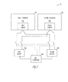
- FIG. 1 is a functional block diagram illustrating an example power generation system that optimizes the power provided to start a generator.
- FIG. 2 is a functional block diagram similar to FIG. 1 where the controller, a first generator and a first battery charger of the example power generation system are all within the same enclosure.
- FIG. 3 is a functional block diagram similar to FIG. 1 where the power generation system includes a plurality of battery chargers.
- FIG. 4 is a functional block diagram similar to FIG. 1 where the power generation system includes multiple batteries.
- FIG. 5 is a functional block diagram similar to FIG. 1 where the power generation system includes a plurality of generators.
- FIG. 6 is a functional block diagram similar to FIG. 1 where the power generation system includes a plurality of generators and multiple batteries.
- FIG. 1 is a functional block diagram illustrating an example power generation system 10.
- the power generation system 10 includes a first generator 11A and a first starter 12A that activates the first generator 11A.
- the power generation system 10 further includes a first battery 13A that is adapted to provide power to the first starter 12A and a second battery 13B adapted to provide power to the first starter 12A.
- a controller 14A determines a state of charge for each of the first battery 13A and the second battery 13B such that the controller 14A determines which of the first battery 13A and second battery 13B provides power to the first starter 12A.
- the controller 14A may command the first battery 13A and/or the second battery 13B to provide power to the first starter 12A.
- the first controller 14A will determine whether (i) the first battery 13A; (ii) the second battery 13B; or (iii) the first and second batteries 13A, 13B together supply current to first starter 12A based on a variety of factors (e.g., the charge level of each of the first and second batteries 13A, 13B).
- the power generation system 10 further includes a first battery charger 15A that supplies current to the first battery 13A and the second battery 13B.
- the controller 30 determines which of the first battery 13A and the second battery 13B receives charging current from the first battery charger 15A (e.g., based on the state of charge for each of the first battery 13A and the second battery 13B).
- first battery charger 15A may be a stand-alone device (as shown in the FIGS.) or a battery charging alternator.
- the type of first battery charger 15A that is included in the power generation system 10 will depend in part on the application where the power generation system 10 is to be used (among other factors).
- the first generator 11A includes an internal combustion engine that drives an alternator. It should be noted that other types of generators (i.e., power generation devices) are contemplated without departing from the scope of the invention.
- the first battery charger 15A is adapted to receive power from a primary power source (not shown).
- the primary power source may be utility power or another electrochemical power source (i.e., battery).
- the controller 14A is a generator controller that operates the first generator 11A. Embodiments are also contemplated where the controller 14A operates the first battery charger 15A, or is a stand-alone device (as shown in FIG. 1 ).
- the controller 14A may display information relating to operation of the power generation system 10.
- the first controller 14A may display a charge level of the first battery 13A and the second battery 13B.
- the controller 14A may display information relating to an optimum starting scenario that indicates which of the first battery 13A and the second battery 13B provide power to the first starter 12A (among other operating parameters that are associated with the power generation system 10).
- the first controller 14A may display the voltage, current and/or temperature at the battery terminals of the first battery 13A and the second battery 13B (or some other part of the batteries). As yet another example, the first controller 14A may display faults, warnings and/or other conditions relating to the health of the first battery 13A, the second battery 13B, the first battery charger 15A and/or the first generator 11A.
- the controller 14A and the first generator 11A are not located within the same enclosure (although they could be in the same enclosure in other embodiments).
- the first battery charger 15A, the controller 14A and the first generator 11A are all located within the same enclosure 20 (although they could be in different enclosure(s) in other embodiments).
- the power generation system 10 further includes a second battery charger 15B that charges the first battery 13A and/or the second battery 13B. It should be noted that although only two battery chargers 15A, 15B are shown in FIG.3 , any number of battery chargers may be included in the power generation system 10.
- the power generation system 10 includes a plurality of batteries 13A, 13B, 13C, 13D, 13E such that the controller 14A determines which of the plurality of batteries 13A, 13B, 13C, 13D, 13E provides power to the first starter 12A. It should be noted that the controller 14A determines that a particular one, some or all of the plurality of batteries 13A, 13B, 13C, 13D, 13E provide power to the first starter 12A.
- FIG. 5 is a functional block diagram where the power generation system 10 includes a first generator 11A and a second generator 11B.
- the power generation system 10 further includes a first starter 12A that activates the first generator and a second starter 12B that activates the second generator 11B.
- the first controller 14A determines whether (i) one or both of the first battery 13A and the second battery 13B provide power to the first starter 12A; and (ii) one or both of the first battery 13A and the second battery 13B provide power to the second starter 12B.
- FIG. 6 is a functional block diagram where the power generation system 10 includes a plurality of generators 11A, 11B and multiple batteries 13A, 13B, 13C, 13D, 13E.
- One, some or all of the batteries 13A, 13B, 13C, 13D, 13E may provide power to the first starter 12A.
- one, some or all of the multiple batteries 13A, 13B, 13C, 13D, 13E may provide power to the second starter 12B.
- a first group of batteries 13A, 13B, 13C in the plurality of batteries 13A, 13B, 13C, 13D, 13E is adapted to provide power to the first starter 12A.
- a second group of batteries 13D, 13E in the plurality of batteries 13A, 13B, 13C, 13D, 13E is adapted to provide power to the second starter 12B.
- the controller(s) 14A, 14B may determine (i) which of the plurality of batteries 13A, 13B, 13C, 13D, 13E in the first group of batteries 13A, 13B, 13C provides power to the first starter 12A; and (ii) which of the plurality of batteries 13A, 13B, 13C, 13D, 13E in the second group of batteries 13D, 13E provides power to the second starter 12B.
- the power generation system 10 includes a first controller 14A that operates the first generator 11A and determines which of the plurality of batteries 13A, 13B, 13C, 13D, 13E in the first group of batteries 13A, 13B, 13C provides power to the first starter 12A.
- the power generation system 10 includes a second controller 14B that operates the second generator 11B and determines which of the plurality of batteries 13A, 13B, 13C, 13D, 13E in the second group of batteries 13D, 13E provides power to the second starter 12B.
- any battery charger and controllers that are included in the power generation system 10 may exchange data via a communication bus that connects the controller(s) and/or the battery charger(s).
- the battery charger(s) and/or controller(s) may exchange data wirelessly.
- the power generation system 10 further includes a server 30 that is connected to the controller 14A over a network (e.g., the Internet I, a local network and/or wireless forms of communication).
- a network e.g., the Internet I, a local network and/or wireless forms of communication.
- the server 30 provides commands to the controller 14A as to which of the first battery 13A and second battery 13B supplies current to the first starter 12A.
- the server 30 may be included in the other embodiments that are shown in FIGS. 2-6 such that the server 30 provides commands to one or more of the controllers 14A, 14B as to which of the multiple batteries 13A, 13B, 13C, 13D, 13E supplies current to which of the first and second starters 12A, 12B (or any other starters that may be included in the power generation system 10).
- the server 30 may communicate directly with at least one of the first and second battery chargers 15A, 15B (or any other battery chargers that may be included in the power generation system 10).
Landscapes
- Engineering & Computer Science (AREA)
- Power Engineering (AREA)
- Charge And Discharge Circuits For Batteries Or The Like (AREA)
- Control Of Charge By Means Of Generators (AREA)
Abstract
Description
- Embodiments pertain to a power generation system, and more particularly to a power generation system that optimizes the power provided to start a generator.
- Power generation systems are used to selectively provide power to various types of power consuming loads. Some power generation systems include batteries that are used to start engines and/or generators within the power generation system. One common cause of generator malfunction is that the starting batteries do not provide sufficient starting current.
- The starting batteries in such conventional power generation systems are typically either charged by a primary power source or a secondary power source (e.g., the generator) when the primary power source becomes unavailable. These types of systems often include a battery charger that charges the starting battery.
- One of drawbacks with existing power generation systems is that the power generation system often tries to start the generator using a starting battery that is unable to provide sufficient starting current to the generator's starter. Therefore, the secondary power source may be unavailable when the primary power source becomes unavailable.
- Another drawback with existing power generation systems is that the generator's starter in such power generation systems is typically unable to draw power from additional sources when the starting battery is unable to provide sufficient starting current to the generator's starter. Therefore, the secondary power source may be unavailable when the primary power source becomes unavailable.
-
FIG. 1 is a functional block diagram illustrating an example power generation system that optimizes the power provided to start a generator. -
FIG. 2 is a functional block diagram similar toFIG. 1 where the controller, a first generator and a first battery charger of the example power generation system are all within the same enclosure. -
FIG. 3 is a functional block diagram similar toFIG. 1 where the power generation system includes a plurality of battery chargers. -
FIG. 4 is a functional block diagram similar toFIG. 1 where the power generation system includes multiple batteries. -
FIG. 5 is a functional block diagram similar toFIG. 1 where the power generation system includes a plurality of generators. -
FIG. 6 is a functional block diagram similar toFIG. 1 where the power generation system includes a plurality of generators and multiple batteries. - The following description and the drawings sufficiently illustrate specific embodiments to enable those skilled in the art to practice them. Other embodiments may incorporate structural, logical, electrical, process, and other changes. Portions and features of some embodiments may be included in, or substituted for, those of other embodiments. Embodiments set forth in the claims encompass all available equivalents of those claims.
-
FIG. 1 is a functional block diagram illustrating an examplepower generation system 10. Thepower generation system 10 includes afirst generator 11A and afirst starter 12A that activates thefirst generator 11A. - The
power generation system 10 further includes afirst battery 13A that is adapted to provide power to thefirst starter 12A and asecond battery 13B adapted to provide power to thefirst starter 12A. Acontroller 14A determines a state of charge for each of thefirst battery 13A and thesecond battery 13B such that thecontroller 14A determines which of thefirst battery 13A andsecond battery 13B provides power to thefirst starter 12A. - It should be noted that the
controller 14A may command thefirst battery 13A and/or thesecond battery 13B to provide power to thefirst starter 12A. Thefirst controller 14A will determine whether (i) thefirst battery 13A; (ii) thesecond battery 13B; or (iii) the first andsecond batteries first starter 12A based on a variety of factors (e.g., the charge level of each of the first andsecond batteries - In the example embodiment that is shown in
FIG. 2 , thepower generation system 10 further includes afirst battery charger 15A that supplies current to thefirst battery 13A and thesecond battery 13B. Thecontroller 30 determines which of thefirst battery 13A and thesecond battery 13B receives charging current from thefirst battery charger 15A (e.g., based on the state of charge for each of thefirst battery 13A and thesecond battery 13B). - It be noted that the
first battery charger 15A may be a stand-alone device (as shown in the FIGS.) or a battery charging alternator. The type offirst battery charger 15A that is included in thepower generation system 10 will depend in part on the application where thepower generation system 10 is to be used (among other factors). - In some embodiments, the
first generator 11A includes an internal combustion engine that drives an alternator. It should be noted that other types of generators (i.e., power generation devices) are contemplated without departing from the scope of the invention. - Embodiments are contemplated where the
first battery charger 15A is adapted to receive power from a primary power source (not shown). As examples, the primary power source may be utility power or another electrochemical power source (i.e., battery). - In some embodiments, the
controller 14A is a generator controller that operates thefirst generator 11A. Embodiments are also contemplated where thecontroller 14A operates thefirst battery charger 15A, or is a stand-alone device (as shown inFIG. 1 ). - It should be noted that the
controller 14A may display information relating to operation of thepower generation system 10. As an example, thefirst controller 14A may display a charge level of thefirst battery 13A and thesecond battery 13B. In addition, thecontroller 14A may display information relating to an optimum starting scenario that indicates which of thefirst battery 13A and thesecond battery 13B provide power to thefirst starter 12A (among other operating parameters that are associated with the power generation system 10). - As another example, the
first controller 14A may display the voltage, current and/or temperature at the battery terminals of thefirst battery 13A and thesecond battery 13B (or some other part of the batteries). As yet another example, thefirst controller 14A may display faults, warnings and/or other conditions relating to the health of thefirst battery 13A, thesecond battery 13B, thefirst battery charger 15A and/or thefirst generator 11A. - In the example embodiment that is illustrated in
FIG. 1 , thecontroller 14A and thefirst generator 11A are not located within the same enclosure (although they could be in the same enclosure in other embodiments). In the example embodiment that is illustrated inFIG. 2 , thefirst battery charger 15A, thecontroller 14A and thefirst generator 11A are all located within the same enclosure 20 (although they could be in different enclosure(s) in other embodiments). - In the example embodiment that is illustrated in
FIG. 3 , thepower generation system 10 further includes asecond battery charger 15B that charges thefirst battery 13A and/or thesecond battery 13B. It should be noted that although only twobattery chargers FIG.3 , any number of battery chargers may be included in thepower generation system 10. - In the example embodiment that is illustrated in
FIG. 4 , thepower generation system 10 includes a plurality ofbatteries controller 14A determines which of the plurality ofbatteries first starter 12A. It should be noted that thecontroller 14A determines that a particular one, some or all of the plurality ofbatteries first starter 12A. -
FIG. 5 is a functional block diagram where thepower generation system 10 includes afirst generator 11A and asecond generator 11B. Thepower generation system 10 further includes afirst starter 12A that activates the first generator and asecond starter 12B that activates thesecond generator 11B. In the example embodiment that is illustrated inFIG. 5 , thefirst controller 14A determines whether (i) one or both of thefirst battery 13A and thesecond battery 13B provide power to thefirst starter 12A; and (ii) one or both of thefirst battery 13A and thesecond battery 13B provide power to thesecond starter 12B. -
FIG. 6 is a functional block diagram where thepower generation system 10 includes a plurality ofgenerators multiple batteries batteries first starter 12A. In addition, one, some or all of themultiple batteries second starter 12B. - In the example embodiment that is illustrated in
FIG. 6 , a first group ofbatteries batteries first starter 12A. In addition, a second group ofbatteries batteries second starter 12B. The controller(s) 14A, 14B may determine (i) which of the plurality ofbatteries batteries first starter 12A; and (ii) which of the plurality ofbatteries batteries second starter 12B. - As shown in
FIG. 6 , thepower generation system 10 includes afirst controller 14A that operates thefirst generator 11A and determines which of the plurality ofbatteries batteries first starter 12A. In addition, thepower generation system 10 includes asecond controller 14B that operates thesecond generator 11B and determines which of the plurality ofbatteries batteries second starter 12B. - It should be noted that any battery charger and controllers that are included in the
power generation system 10 may exchange data via a communication bus that connects the controller(s) and/or the battery charger(s). In addition, the battery charger(s) and/or controller(s) may exchange data wirelessly. - Referring again to
FIG. 1 , thepower generation system 10 further includes aserver 30 that is connected to thecontroller 14A over a network (e.g., the Internet I, a local network and/or wireless forms of communication). In some embodiments, theserver 30 provides commands to thecontroller 14A as to which of thefirst battery 13A andsecond battery 13B supplies current to thefirst starter 12A. - It should be noted that the
server 30 may be included in the other embodiments that are shown inFIGS. 2-6 such that theserver 30 provides commands to one or more of thecontrollers multiple batteries second starters server 30 may communicate directly with at least one of the first andsecond battery chargers - The Abstract is provided to comply with 37 C.F.R. Section 1.72(b) requiring an abstract that will allow the reader to ascertain the nature and gist of the technical disclosure. It is submitted with the understanding that it will not be used to limit or interpret the scope or meaning of the claims. The following claims are hereby incorporated into the detailed description, with each claim standing on its own as a separate embodiment.
The present invention can also be described by means of the following clauses: - 1. A power generation system comprising:
- a first generator;
- a first starter that activates the first generator;
- a first battery adapted to provide power to the first starter;
- a second battery adapted to provide power to the first starter; and
- a controller that determines a state of charge for each of the first battery and the second battery, wherein the controller determines which of the first battery and second battery provides power to the first starter.
- 2. The power generation system of clause 1, wherein the controller commands the first battery and the second battery to provide power to the first starter.
- 3. The power generation system of clause 1, wherein the controller is a generator controller that operates the first generator.
- 4. The power generation system of clause 1, further comprising a first battery charger that supplies current to the first battery and the second battery.
- 5. The power generation system of clause 1, wherein the first battery charger is a battery charging alternator.
- 6. The power generation system of clause 5, wherein the first battery charger is selectively connected to a primary power source or the first generator.
- 7. The power generation system of clause 6, wherein the primary power source is utility power.
- 8. The power generation system of clause 6, wherein the primary power source is an electrochemical power source.
- 9. The power generation system of clause 1, wherein the controller is part of the first battery charger.
- 10. The power generation system of clause 1, wherein the controller displays information relating to an optimum starting scenario that indicates which of the first battery and the second battery provide power to the first starter.
- 11. The power generation system of clause 1, further comprising an enclosure such that the first generator, the controller, and first battery charger are within the enclosure.
- 12. The power generation system of clause 4, further comprising a second battery charger that charges at least one of the first battery and the second battery, and wherein the first battery charger charges at least one of the first battery and the second battery.
- 13. The power generation system of clause 1, further comprising a plurality of batteries, wherein the controller determines which of the plurality of batteries provides power to the first starter.
- 14. The power generation system of clause 13, wherein the controller determines that each of the plurality of batteries provide power to the first starter.
- 15. The power generation system of clause 1, further comprising a server that is connected to the controller over a network, wherein the server determines which of the first battery and second battery provide power to the first starter.
- 16. A power generation system comprising:
- a first generator;
- a first starter that activates the first generator;
- a second generator;
- a second starter that activates the second generator;
- a first battery adapted to provide power to the first starter and the second starter;
- a second battery adapted to provide power to the first starter and the second starter; and
- a controller that determines a state of charge for each of the first battery and
the second battery, wherein the controller determines which of the first battery and second battery provide power to the first starter and which of the first battery and second battery provide power to the second starter.
- 17. The power generation system of clause 16, wherein the controller commands the first battery and the second battery to provide power to the first starter, and wherein the controller commands the first battery and the second battery to provide power to the second starter.
- 18. The power generation system of clause 16, further comprising a plurality of batteries, wherein a first group of batteries in the plurality of batteries is adapted to provide power to the first start starter, a second group in the plurality of batteries is adapted to provide power to the second starter, wherein the controller determines which of the plurality of batteries in the first group of batteries provides power to the first starter, and wherein the controller determines which of the plurality of batteries in the second group of batteries provides power to the second starter.
- 19. The power generation system of clause 18, wherein the controller includes a first controller that operates the first generator and determines which of the plurality of batteries in the first group of batteries provides power to the first starter, and a second controller that operates the second generator and determines which of the plurality of batteries in the second group of batteries provides power to the second starter.
- 20. The power generation system of clause 16, wherein the first battery and the second battery are part of a plurality of batteries, wherein the controller determines which of the batteries in the plurality of batteries provides power to the first starter and the second starter.
Claims (15)
- A power generation system comprising:a first generator;a first starter that activates the first generator;a first battery adapted to provide power to the first starter;a second battery adapted to provide power to the first starter; anda controller that determines a state of charge for each of the first battery and the second battery, wherein the controller determines which of the first battery and second battery provides power to the first starter.
- The power generation system of claim 1, wherein the controller commands the first battery and the second battery to provide power to the first starter.
- The power generation system of claim 1, wherein the controller is a generator controller that operates the first generator.
- The power generation system of claim 1, further comprising a first battery charger that supplies current to the first battery and the second battery.
- The power generation system of claim 1, wherein the first battery charger is a battery charging alternator.
- The power generation system of claim 5, wherein the first battery charger is selectively connected to a primary power source or the first generator.
- The power generation system of claim 6, wherein the primary power source is utility power.
- The power generation system of claim 6, wherein the primary power source is an electrochemical power source.
- The power generation system of claim 1, wherein the controller is part of the first battery charger.
- The power generation system of claim 1, wherein the controller displays information relating to an optimum starting scenario that indicates which of the first battery and the second battery provide power to the first starter.
- The power generation system of claim 1, further comprising an enclosure such that the first generator, the controller, and first battery charger are within the enclosure.
- The power generation system of claim 4, further comprising a second battery charger that charges at least one of the first battery and the second battery, and wherein the first battery charger charges at least one of the first battery and the second battery.
- The power generation system of claim 1, further comprising a plurality of batteries, wherein the controller determines which of the plurality of batteries provides power to the first starter.
- The power generation system of claim 13, wherein the controller determines that each of the plurality of batteries provide power to the first starter.
- The power generation system of claim 1, further comprising a server that is connected to the controller over a network, wherein the server determines which of the first battery and second battery provide power to the first starter.
Applications Claiming Priority (1)
| Application Number | Priority Date | Filing Date | Title |
|---|---|---|---|
| US13/627,056 US8829855B2 (en) | 2012-09-26 | 2012-09-26 | Power generation system that optimizes the power provided to start a generator |
Publications (2)
| Publication Number | Publication Date |
|---|---|
| EP2713476A1 true EP2713476A1 (en) | 2014-04-02 |
| EP2713476B1 EP2713476B1 (en) | 2020-02-26 |
Family
ID=49170565
Family Applications (1)
| Application Number | Title | Priority Date | Filing Date |
|---|---|---|---|
| EP13183671.0A Active EP2713476B1 (en) | 2012-09-26 | 2013-09-10 | Power generation system that optimizes the power provided to start a generator |
Country Status (4)
| Country | Link |
|---|---|
| US (1) | US8829855B2 (en) |
| EP (1) | EP2713476B1 (en) |
| CN (1) | CN103683382B (en) |
| IN (1) | IN2013MU02658A (en) |
Families Citing this family (5)
| Publication number | Priority date | Publication date | Assignee | Title |
|---|---|---|---|---|
| US9219294B2 (en) | 2012-08-22 | 2015-12-22 | Eric D. Albsmeier | Power management system that changes the operating conditions of a battery charger |
| US9331498B2 (en) | 2012-09-07 | 2016-05-03 | Kohler Co. | Power generation system that provides efficient battery charger selection |
| US10988030B2 (en) * | 2014-09-26 | 2021-04-27 | Francis Xavier Gentile | Electric motor, generator and battery combination |
| CN112994126B (en) * | 2019-12-13 | 2025-06-03 | 北京小米移动软件有限公司 | Charging circuit, electronic device, charging method and device |
| JP7585095B2 (en) * | 2021-03-05 | 2024-11-18 | 本田技研工業株式会社 | Power Supply Circuit |
Citations (3)
| Publication number | Priority date | Publication date | Assignee | Title |
|---|---|---|---|---|
| JP2005264860A (en) * | 2004-03-19 | 2005-09-29 | Mazda Motor Corp | Vehicle power supply |
| DE102008051078A1 (en) * | 2007-10-12 | 2009-04-16 | Denso Corp., Kariya-shi | Power controlling device for vehicle e.g. lorry, on-board power generator, has excitation device supplying current of winding in generator when frequency of generator is smaller and power generation voltage is higher than reference voltage |
| US20110175357A1 (en) * | 2010-01-19 | 2011-07-21 | Frank Navetta | Redundant combustion engine starting systems for emergency generators |
Family Cites Families (34)
| Publication number | Priority date | Publication date | Assignee | Title |
|---|---|---|---|---|
| US5206579A (en) | 1990-02-26 | 1993-04-27 | Nippon Densan Corporation | Battery charger and charge controller therefor |
| US5122722A (en) | 1991-01-17 | 1992-06-16 | Motorola, Inc. | Battery charging system |
| US5166596A (en) | 1991-08-29 | 1992-11-24 | Motorola, Inc. | Battery charger having variable-magnitude charging current source |
| US5420493A (en) | 1992-06-30 | 1995-05-30 | Apple Computer, Inc. | Power supply and battery charger |
| US5504416A (en) | 1993-12-15 | 1996-04-02 | Unitrode Corporation | Battery charger circuit including battery temperature control |
| US5659240A (en) | 1995-02-16 | 1997-08-19 | General Electric Company | Intelligent battery charger for electric drive system batteries |
| US6018227A (en) | 1998-06-22 | 2000-01-25 | Stryker Corporation | Battery charger especially useful with sterilizable, rechargeable battery packs |
| EP1025606A1 (en) | 1998-08-13 | 2000-08-09 | Milwaukee Electric Tool Corporation | Battery charger |
| DE19842657A1 (en) * | 1998-09-17 | 2000-03-23 | Volkswagen Ag | Two-battery system |
| US6333619B1 (en) | 2000-03-15 | 2001-12-25 | Jaime H Chavez | Cyclical battery charger with incremental and decremental current and a method of operation thereof |
| US6215282B1 (en) | 2000-06-19 | 2001-04-10 | Qualcomm Incorporated | Battery charging system employing multi-mode low power fast charge process |
| US7348760B2 (en) * | 2000-09-21 | 2008-03-25 | O2Micro International Limited | Power management topologies |
| TW563282B (en) | 2002-03-22 | 2003-11-21 | Tai-Her Yang | Automatic surveillant revolving storage battery auxiliary charge system |
| JP3983681B2 (en) | 2003-01-14 | 2007-09-26 | 株式会社マキタ | Charger |
| DE10305058B3 (en) * | 2003-02-07 | 2004-03-25 | Daimlerchrysler Ag | Power supply circuit for vehicle electrical system has starter/generator connected to system via branches with switches controlled depending on battery, energy storage device charge, operating state |
| US6879134B2 (en) * | 2003-02-11 | 2005-04-12 | O2Micro International Limited | Selector circuit for power management in multiple battery systems |
| US6930469B2 (en) | 2003-07-10 | 2005-08-16 | Vector Products, Inc. | Battery charger with a timed high-current stage |
| JP3987833B2 (en) | 2004-02-27 | 2007-10-10 | 株式会社日立製作所 | Vehicle drive device |
| JP3972930B2 (en) | 2004-09-30 | 2007-09-05 | 松下電工株式会社 | Charger |
| US7274975B2 (en) * | 2005-06-06 | 2007-09-25 | Gridpoint, Inc. | Optimized energy management system |
| US7456611B2 (en) | 2005-08-11 | 2008-11-25 | Semiconductor Components Industries, L.L.C. | Multi-current battery charger circuit and method therefor |
| US9118206B2 (en) | 2006-11-16 | 2015-08-25 | Cummins Power Generation Ip, Inc. | Management of an electric power generation and storage system |
| US7573145B2 (en) | 2006-11-16 | 2009-08-11 | Cummins Power Generation Ip, Inc. | Electric power generation system controlled to reduce perception of operational changes |
| US7855466B2 (en) | 2006-12-29 | 2010-12-21 | Cummins Power Generation Ip, Inc. | Electric power generation system with current-controlled power boost |
| US8558511B2 (en) | 2009-04-07 | 2013-10-15 | Battelle Memorial Institute | Method and apparatus for smart battery charging including a plurality of controllers each monitoring input variables |
| US8022572B2 (en) | 2009-04-22 | 2011-09-20 | General Electric Company | Genset system with energy storage for transient response |
| JP4939570B2 (en) | 2009-05-15 | 2012-05-30 | 三菱電機株式会社 | Power supply |
| US20110084650A1 (en) | 2009-10-09 | 2011-04-14 | Charles Industries, Ltd. | Battery charger |
| US8552588B2 (en) | 2009-11-05 | 2013-10-08 | Tai-Her Yang | Battery charging coaction and output system with current limit supply |
| JP2011151944A (en) | 2010-01-21 | 2011-08-04 | Panasonic Corp | Power generator |
| EP2367258B1 (en) | 2010-03-16 | 2018-06-27 | CTEK Sweden AB | A combined battery charger and battery equalizer |
| JP5412355B2 (en) | 2010-03-31 | 2014-02-12 | 株式会社日立製作所 | Battery charging device, battery charging circuit, and semiconductor integrated circuit device |
| JP5396404B2 (en) | 2011-01-14 | 2014-01-22 | 株式会社日立ソリューションズ | Charging device, charging system |
| US10036335B2 (en) | 2011-09-15 | 2018-07-31 | General Electric Company | Systems and methods for diagnosing an engine |
-
2012
- 2012-09-26 US US13/627,056 patent/US8829855B2/en active Active
-
2013
- 2013-08-13 IN IN2658MU2013 patent/IN2013MU02658A/en unknown
- 2013-09-10 EP EP13183671.0A patent/EP2713476B1/en active Active
- 2013-09-18 CN CN201310430572.9A patent/CN103683382B/en active Active
Patent Citations (3)
| Publication number | Priority date | Publication date | Assignee | Title |
|---|---|---|---|---|
| JP2005264860A (en) * | 2004-03-19 | 2005-09-29 | Mazda Motor Corp | Vehicle power supply |
| DE102008051078A1 (en) * | 2007-10-12 | 2009-04-16 | Denso Corp., Kariya-shi | Power controlling device for vehicle e.g. lorry, on-board power generator, has excitation device supplying current of winding in generator when frequency of generator is smaller and power generation voltage is higher than reference voltage |
| US20110175357A1 (en) * | 2010-01-19 | 2011-07-21 | Frank Navetta | Redundant combustion engine starting systems for emergency generators |
Also Published As
| Publication number | Publication date |
|---|---|
| US8829855B2 (en) | 2014-09-09 |
| CN103683382B (en) | 2019-08-16 |
| US20140084598A1 (en) | 2014-03-27 |
| CN103683382A (en) | 2014-03-26 |
| IN2013MU02658A (en) | 2015-06-19 |
| EP2713476B1 (en) | 2020-02-26 |
Similar Documents
| Publication | Publication Date | Title |
|---|---|---|
| US9331498B2 (en) | Power generation system that provides efficient battery charger selection | |
| US9941723B2 (en) | Power management system that changes the operating conditions of a battery charger | |
| US12157386B2 (en) | Control system and energy management method | |
| US10486540B2 (en) | Electric power charging of vehicle based on charging time schedule | |
| CN109835207B (en) | Charging parking space guiding method, computer equipment and storage medium | |
| JP2014183723A (en) | Charging connection device | |
| US8829855B2 (en) | Power generation system that optimizes the power provided to start a generator | |
| EP2683078A2 (en) | Generator management system that selectively activates generators based on an operating parameter | |
| JP2016073195A (en) | Methods and systems for multiple source energy storage, management and control | |
| DE112012006375T5 (en) | VEHICLE CRUISE CONTROL DEVICE SUPPORT | |
| CN103023089A (en) | Power supply system, electric vehicle and charging adapter | |
| US10906414B2 (en) | Systems and methods for restarting electrified vehicle charging without unplugging | |
| EP3024115A1 (en) | Rapid charging method for storage cell, rapid charging system, and program | |
| CN105008171A (en) | Onboard device and EV management system | |
| JP2023148527A (en) | Charging control system | |
| WO2013124841A1 (en) | Charging management method and system | |
| CN108496289B (en) | Battery charging control method, charging equipment, user terminal equipment and system | |
| US20130300363A1 (en) | Vehicle and vehicle control method | |
| CN111384732A (en) | Method for charging a battery of a vehicle, battery charging device and vehicle | |
| KR101754363B1 (en) | Apparatus and method Electric Vehicle battery charging | |
| EP2654174A2 (en) | Charging an energy storage device with a variable speed generator | |
| KR20140018593A (en) | Central server and charge control system for an electric moving body according to rate system using the same | |
| US20190389327A1 (en) | Charging control apparatus, charging control method, and storage medium | |
| JP2019110678A (en) | Charge control device | |
| CN119283701B (en) | Wireless communication methods, devices, equipment and media between vehicles and charging stations |
Legal Events
| Date | Code | Title | Description |
|---|---|---|---|
| PUAI | Public reference made under article 153(3) epc to a published international application that has entered the european phase |
Free format text: ORIGINAL CODE: 0009012 |
|
| AK | Designated contracting states |
Kind code of ref document: A1 Designated state(s): AL AT BE BG CH CY CZ DE DK EE ES FI FR GB GR HR HU IE IS IT LI LT LU LV MC MK MT NL NO PL PT RO RS SE SI SK SM TR |
|
| AX | Request for extension of the european patent |
Extension state: BA ME |
|
| 17P | Request for examination filed |
Effective date: 20141002 |
|
| RBV | Designated contracting states (corrected) |
Designated state(s): AL AT BE BG CH CY CZ DE DK EE ES FI FR GB GR HR HU IE IS IT LI LT LU LV MC MK MT NL NO PL PT RO RS SE SI SK SM TR |
|
| 17Q | First examination report despatched |
Effective date: 20160222 |
|
| STAA | Information on the status of an ep patent application or granted ep patent |
Free format text: STATUS: EXAMINATION IS IN PROGRESS |
|
| GRAP | Despatch of communication of intention to grant a patent |
Free format text: ORIGINAL CODE: EPIDOSNIGR1 |
|
| STAA | Information on the status of an ep patent application or granted ep patent |
Free format text: STATUS: GRANT OF PATENT IS INTENDED |
|
| INTG | Intention to grant announced |
Effective date: 20190919 |
|
| GRAS | Grant fee paid |
Free format text: ORIGINAL CODE: EPIDOSNIGR3 |
|
| GRAA | (expected) grant |
Free format text: ORIGINAL CODE: 0009210 |
|
| STAA | Information on the status of an ep patent application or granted ep patent |
Free format text: STATUS: THE PATENT HAS BEEN GRANTED |
|
| AK | Designated contracting states |
Kind code of ref document: B1 Designated state(s): AL AT BE BG CH CY CZ DE DK EE ES FI FR GB GR HR HU IE IS IT LI LT LU LV MC MK MT NL NO PL PT RO RS SE SI SK SM TR |
|
| REG | Reference to a national code |
Ref country code: GB Ref legal event code: FG4D |
|
| REG | Reference to a national code |
Ref country code: CH Ref legal event code: EP |
|
| REG | Reference to a national code |
Ref country code: DE Ref legal event code: R096 Ref document number: 602013066181 Country of ref document: DE |
|
| REG | Reference to a national code |
Ref country code: AT Ref legal event code: REF Ref document number: 1238831 Country of ref document: AT Kind code of ref document: T Effective date: 20200315 |
|
| REG | Reference to a national code |
Ref country code: IE Ref legal event code: FG4D |
|
| PG25 | Lapsed in a contracting state [announced via postgrant information from national office to epo] |
Ref country code: NO Free format text: LAPSE BECAUSE OF FAILURE TO SUBMIT A TRANSLATION OF THE DESCRIPTION OR TO PAY THE FEE WITHIN THE PRESCRIBED TIME-LIMIT Effective date: 20200526 Ref country code: FI Free format text: LAPSE BECAUSE OF FAILURE TO SUBMIT A TRANSLATION OF THE DESCRIPTION OR TO PAY THE FEE WITHIN THE PRESCRIBED TIME-LIMIT Effective date: 20200226 Ref country code: RS Free format text: LAPSE BECAUSE OF FAILURE TO SUBMIT A TRANSLATION OF THE DESCRIPTION OR TO PAY THE FEE WITHIN THE PRESCRIBED TIME-LIMIT Effective date: 20200226 |
|
| REG | Reference to a national code |
Ref country code: NL Ref legal event code: MP Effective date: 20200226 |
|
| REG | Reference to a national code |
Ref country code: LT Ref legal event code: MG4D |
|
| PG25 | Lapsed in a contracting state [announced via postgrant information from national office to epo] |
Ref country code: IS Free format text: LAPSE BECAUSE OF FAILURE TO SUBMIT A TRANSLATION OF THE DESCRIPTION OR TO PAY THE FEE WITHIN THE PRESCRIBED TIME-LIMIT Effective date: 20200626 Ref country code: SE Free format text: LAPSE BECAUSE OF FAILURE TO SUBMIT A TRANSLATION OF THE DESCRIPTION OR TO PAY THE FEE WITHIN THE PRESCRIBED TIME-LIMIT Effective date: 20200226 Ref country code: LV Free format text: LAPSE BECAUSE OF FAILURE TO SUBMIT A TRANSLATION OF THE DESCRIPTION OR TO PAY THE FEE WITHIN THE PRESCRIBED TIME-LIMIT Effective date: 20200226 Ref country code: BG Free format text: LAPSE BECAUSE OF FAILURE TO SUBMIT A TRANSLATION OF THE DESCRIPTION OR TO PAY THE FEE WITHIN THE PRESCRIBED TIME-LIMIT Effective date: 20200526 Ref country code: GR Free format text: LAPSE BECAUSE OF FAILURE TO SUBMIT A TRANSLATION OF THE DESCRIPTION OR TO PAY THE FEE WITHIN THE PRESCRIBED TIME-LIMIT Effective date: 20200527 Ref country code: HR Free format text: LAPSE BECAUSE OF FAILURE TO SUBMIT A TRANSLATION OF THE DESCRIPTION OR TO PAY THE FEE WITHIN THE PRESCRIBED TIME-LIMIT Effective date: 20200226 |
|
| PG25 | Lapsed in a contracting state [announced via postgrant information from national office to epo] |
Ref country code: NL Free format text: LAPSE BECAUSE OF FAILURE TO SUBMIT A TRANSLATION OF THE DESCRIPTION OR TO PAY THE FEE WITHIN THE PRESCRIBED TIME-LIMIT Effective date: 20200226 |
|
| PG25 | Lapsed in a contracting state [announced via postgrant information from national office to epo] |
Ref country code: EE Free format text: LAPSE BECAUSE OF FAILURE TO SUBMIT A TRANSLATION OF THE DESCRIPTION OR TO PAY THE FEE WITHIN THE PRESCRIBED TIME-LIMIT Effective date: 20200226 Ref country code: SM Free format text: LAPSE BECAUSE OF FAILURE TO SUBMIT A TRANSLATION OF THE DESCRIPTION OR TO PAY THE FEE WITHIN THE PRESCRIBED TIME-LIMIT Effective date: 20200226 Ref country code: ES Free format text: LAPSE BECAUSE OF FAILURE TO SUBMIT A TRANSLATION OF THE DESCRIPTION OR TO PAY THE FEE WITHIN THE PRESCRIBED TIME-LIMIT Effective date: 20200226 Ref country code: LT Free format text: LAPSE BECAUSE OF FAILURE TO SUBMIT A TRANSLATION OF THE DESCRIPTION OR TO PAY THE FEE WITHIN THE PRESCRIBED TIME-LIMIT Effective date: 20200226 Ref country code: DK Free format text: LAPSE BECAUSE OF FAILURE TO SUBMIT A TRANSLATION OF THE DESCRIPTION OR TO PAY THE FEE WITHIN THE PRESCRIBED TIME-LIMIT Effective date: 20200226 Ref country code: PT Free format text: LAPSE BECAUSE OF FAILURE TO SUBMIT A TRANSLATION OF THE DESCRIPTION OR TO PAY THE FEE WITHIN THE PRESCRIBED TIME-LIMIT Effective date: 20200719 Ref country code: CZ Free format text: LAPSE BECAUSE OF FAILURE TO SUBMIT A TRANSLATION OF THE DESCRIPTION OR TO PAY THE FEE WITHIN THE PRESCRIBED TIME-LIMIT Effective date: 20200226 Ref country code: SK Free format text: LAPSE BECAUSE OF FAILURE TO SUBMIT A TRANSLATION OF THE DESCRIPTION OR TO PAY THE FEE WITHIN THE PRESCRIBED TIME-LIMIT Effective date: 20200226 Ref country code: RO Free format text: LAPSE BECAUSE OF FAILURE TO SUBMIT A TRANSLATION OF THE DESCRIPTION OR TO PAY THE FEE WITHIN THE PRESCRIBED TIME-LIMIT Effective date: 20200226 |
|
| REG | Reference to a national code |
Ref country code: AT Ref legal event code: MK05 Ref document number: 1238831 Country of ref document: AT Kind code of ref document: T Effective date: 20200226 |
|
| REG | Reference to a national code |
Ref country code: DE Ref legal event code: R097 Ref document number: 602013066181 Country of ref document: DE |
|
| PLBE | No opposition filed within time limit |
Free format text: ORIGINAL CODE: 0009261 |
|
| STAA | Information on the status of an ep patent application or granted ep patent |
Free format text: STATUS: NO OPPOSITION FILED WITHIN TIME LIMIT |
|
| PG25 | Lapsed in a contracting state [announced via postgrant information from national office to epo] |
Ref country code: IT Free format text: LAPSE BECAUSE OF FAILURE TO SUBMIT A TRANSLATION OF THE DESCRIPTION OR TO PAY THE FEE WITHIN THE PRESCRIBED TIME-LIMIT Effective date: 20200226 Ref country code: AT Free format text: LAPSE BECAUSE OF FAILURE TO SUBMIT A TRANSLATION OF THE DESCRIPTION OR TO PAY THE FEE WITHIN THE PRESCRIBED TIME-LIMIT Effective date: 20200226 |
|
| 26N | No opposition filed |
Effective date: 20201127 |
|
| PG25 | Lapsed in a contracting state [announced via postgrant information from national office to epo] |
Ref country code: SI Free format text: LAPSE BECAUSE OF FAILURE TO SUBMIT A TRANSLATION OF THE DESCRIPTION OR TO PAY THE FEE WITHIN THE PRESCRIBED TIME-LIMIT Effective date: 20200226 Ref country code: PL Free format text: LAPSE BECAUSE OF FAILURE TO SUBMIT A TRANSLATION OF THE DESCRIPTION OR TO PAY THE FEE WITHIN THE PRESCRIBED TIME-LIMIT Effective date: 20200226 |
|
| PG25 | Lapsed in a contracting state [announced via postgrant information from national office to epo] |
Ref country code: MC Free format text: LAPSE BECAUSE OF FAILURE TO SUBMIT A TRANSLATION OF THE DESCRIPTION OR TO PAY THE FEE WITHIN THE PRESCRIBED TIME-LIMIT Effective date: 20200226 |
|
| REG | Reference to a national code |
Ref country code: CH Ref legal event code: PL |
|
| REG | Reference to a national code |
Ref country code: BE Ref legal event code: MM Effective date: 20200930 |
|
| PG25 | Lapsed in a contracting state [announced via postgrant information from national office to epo] |
Ref country code: LU Free format text: LAPSE BECAUSE OF NON-PAYMENT OF DUE FEES Effective date: 20200910 |
|
| PG25 | Lapsed in a contracting state [announced via postgrant information from national office to epo] |
Ref country code: BE Free format text: LAPSE BECAUSE OF NON-PAYMENT OF DUE FEES Effective date: 20200930 Ref country code: CH Free format text: LAPSE BECAUSE OF NON-PAYMENT OF DUE FEES Effective date: 20200930 Ref country code: IE Free format text: LAPSE BECAUSE OF NON-PAYMENT OF DUE FEES Effective date: 20200910 Ref country code: LI Free format text: LAPSE BECAUSE OF NON-PAYMENT OF DUE FEES Effective date: 20200930 |
|
| PG25 | Lapsed in a contracting state [announced via postgrant information from national office to epo] |
Ref country code: TR Free format text: LAPSE BECAUSE OF FAILURE TO SUBMIT A TRANSLATION OF THE DESCRIPTION OR TO PAY THE FEE WITHIN THE PRESCRIBED TIME-LIMIT Effective date: 20200226 Ref country code: MT Free format text: LAPSE BECAUSE OF FAILURE TO SUBMIT A TRANSLATION OF THE DESCRIPTION OR TO PAY THE FEE WITHIN THE PRESCRIBED TIME-LIMIT Effective date: 20200226 Ref country code: CY Free format text: LAPSE BECAUSE OF FAILURE TO SUBMIT A TRANSLATION OF THE DESCRIPTION OR TO PAY THE FEE WITHIN THE PRESCRIBED TIME-LIMIT Effective date: 20200226 |
|
| PG25 | Lapsed in a contracting state [announced via postgrant information from national office to epo] |
Ref country code: MK Free format text: LAPSE BECAUSE OF FAILURE TO SUBMIT A TRANSLATION OF THE DESCRIPTION OR TO PAY THE FEE WITHIN THE PRESCRIBED TIME-LIMIT Effective date: 20200226 Ref country code: AL Free format text: LAPSE BECAUSE OF FAILURE TO SUBMIT A TRANSLATION OF THE DESCRIPTION OR TO PAY THE FEE WITHIN THE PRESCRIBED TIME-LIMIT Effective date: 20200226 |
|
| P01 | Opt-out of the competence of the unified patent court (upc) registered |
Effective date: 20230707 |
|
| REG | Reference to a national code |
Ref country code: GB Ref legal event code: 732E Free format text: REGISTERED BETWEEN 20240725 AND 20240731 |
|
| REG | Reference to a national code |
Ref country code: DE Ref legal event code: R081 Ref document number: 602013066181 Country of ref document: DE Owner name: DISCOVERY ENERGY, LLC, KOHLER, US Free format text: FORMER OWNER: KOHLER CO., KOHLER, WIS., US |
|
| PGFP | Annual fee paid to national office [announced via postgrant information from national office to epo] |
Ref country code: DE Payment date: 20250926 Year of fee payment: 13 |
|
| PGFP | Annual fee paid to national office [announced via postgrant information from national office to epo] |
Ref country code: GB Payment date: 20250701 Year of fee payment: 13 |
|
| PGFP | Annual fee paid to national office [announced via postgrant information from national office to epo] |
Ref country code: FR Payment date: 20250925 Year of fee payment: 13 |