EP2713388A2 - Filament lamp for heating - Google Patents
Filament lamp for heating Download PDFInfo
- Publication number
- EP2713388A2 EP2713388A2 EP13179860.5A EP13179860A EP2713388A2 EP 2713388 A2 EP2713388 A2 EP 2713388A2 EP 13179860 A EP13179860 A EP 13179860A EP 2713388 A2 EP2713388 A2 EP 2713388A2
- Authority
- EP
- European Patent Office
- Prior art keywords
- emitting part
- workpiece
- arc
- shaped
- filament lamp
- Prior art date
- Legal status (The legal status is an assumption and is not a legal conclusion. Google has not performed a legal analysis and makes no representation as to the accuracy of the status listed.)
- Withdrawn
Links
Images







Classifications
-
- H—ELECTRICITY
- H05—ELECTRIC TECHNIQUES NOT OTHERWISE PROVIDED FOR
- H05B—ELECTRIC HEATING; ELECTRIC LIGHT SOURCES NOT OTHERWISE PROVIDED FOR; CIRCUIT ARRANGEMENTS FOR ELECTRIC LIGHT SOURCES, IN GENERAL
- H05B3/00—Ohmic-resistance heating
- H05B3/0033—Heating devices using lamps
-
- F—MECHANICAL ENGINEERING; LIGHTING; HEATING; WEAPONS; BLASTING
- F21—LIGHTING
- F21S—NON-PORTABLE LIGHTING DEVICES; SYSTEMS THEREOF; VEHICLE LIGHTING DEVICES SPECIALLY ADAPTED FOR VEHICLE EXTERIORS
- F21S2/00—Systems of lighting devices, not provided for in main groups F21S4/00 - F21S10/00 or F21S19/00, e.g. of modular construction
- F21S2/005—Systems of lighting devices, not provided for in main groups F21S4/00 - F21S10/00 or F21S19/00, e.g. of modular construction of modular construction
-
- H—ELECTRICITY
- H05—ELECTRIC TECHNIQUES NOT OTHERWISE PROVIDED FOR
- H05B—ELECTRIC HEATING; ELECTRIC LIGHT SOURCES NOT OTHERWISE PROVIDED FOR; CIRCUIT ARRANGEMENTS FOR ELECTRIC LIGHT SOURCES, IN GENERAL
- H05B3/00—Ohmic-resistance heating
- H05B3/0033—Heating devices using lamps
- H05B3/0038—Heating devices using lamps for industrial applications
- H05B3/0047—Heating devices using lamps for industrial applications for semiconductor manufacture
-
- H—ELECTRICITY
- H10—SEMICONDUCTOR DEVICES; ELECTRIC SOLID-STATE DEVICES NOT OTHERWISE PROVIDED FOR
- H10P—GENERIC PROCESSES OR APPARATUS FOR THE MANUFACTURE OR TREATMENT OF DEVICES COVERED BY CLASS H10
- H10P72/00—Handling or holding of wafers, substrates or devices during manufacture or treatment thereof
- H10P72/04—Apparatus for manufacture or treatment
- H10P72/0431—Apparatus for thermal treatment
- H10P72/0436—Apparatus for thermal treatment mainly by radiation
Definitions
- the present invention relates generally to filament lamps for heating disk-shaped workpieces and, more particularly, to a filament lamp for heating a semiconductor wafer in such a way that the filament lamp and the semiconductor wafer rotate relative to each other.
- filament lamps are widely used as heating sources for heat treatment such as annealing, oxidation, diffusion when forming a film such as an oxide film, a metal film or a semiconductor film on a substrate, e.g. a semiconductor wafer, or the like.
- a heating apparatus using such a heating source is generally configured such that the heating source heats a workpiece when the workpiece is rotating. This technique was disclosed in Japanese Patent Application Publication No. 2010-086985 (Prior Art Document 1).
- the conventional heating apparatus uses a linear tubular lamp, which may easily cause nonuniformity in light radiation between a central portion and a perimeter portion of a workpiece.
- FIG. 9 shows this nonuniformity phenomenon.
- a linear tubular lamp 20 radiates light onto a workpiece W that is rotating, a light radiation rate is different between a central portion A and a perimeter portion B of the workpiece W.
- the central portion A of the workpiece W is heated to a high temperature, while the perimeter portion B thereof is heated to a lower temperature.
- the overall area of the workpiece W is not uniformly heated, it is impossible to reliably and uniformly process the workpiece. This causes a defective product.
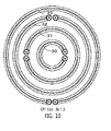
- FIG. 10 a heating source having a plurality of annular lamps which face a rotating workpiece was proposed in Japanese Patent Application Publication No. 1999-176389 (Prior Art Document 2).
- the structure of this heating source is illustrated in FIG. 10 .
- the annular lamps 30, 31, 32 and 33 are concentrically arranged.
- the annular lamps 30, 31, 32 and 33 are individually controlled to uniformly heat the overall area ofa workpiece.
- an object ofthe present invention is to provide a filament lamp for heating a disk-shaped workpiece in such a way that the filament lamp radiates light onto the disk-shaped workpiece while the filament lamp and the disk-shaped workpiece rotate relative to each other, and a heating apparatus using the filament lamp, and, particularly, to a structure that enables heating temperature to be maintained uniformly on a central portion and a perimeter portion of the disk-shaped workpiece so that the workpiece can be uniformly heated without separately controlling the temperature of the filament lamp.
- the present invention provides a filament lamp for heating a disk-shaped workpiece in such a way that the filament lamp rotates relative to the disk-shaped workpiece and radiates light thereonto, the filament lamp including: an arc-shaped emitting part extending in a circumferential direction of the relative rotation; and an auxiliary emitting part disposed inside a circle extending along the arc-shaped emitting part and extending from the arc-shaped emitting part in a direction crossing the circle.
- the auxiliary emitting part may have a linear shape.
- the auxiliary emitting part may be provided in a medial portion of the arc-shaped emitting part.
- the auxiliary emitting part may be integrally connected to an end of the arc-shaped emitting part.
- the arc-shaped emitting part and the auxiliary emitting part may be integrally formed to be round.
- arc-shaped emitting parts ofthe filament lamps uniformly heat areas ofthe workpiece with respect to the circumferential direction.
- areas of the workpiece that correspond to spaces between the arc-shaped emitting parts of the filament lamps pass just below corresponding auxiliary emitting parts of the filament lamps when the filament lamps and the workpiece rotate relative to each other. That is, all areas of the workpiece with respect to the radial direction can pass just below the filament lamps. As a result, heating temperature of the areas ofthe workpiece with respect to the radial direction can also become uniform.
- each filament lamp includes the arc-shaped emitting part and the auxiliary emitting part, wiring work can be facilitated using space between the opposite ends of the filament lamp.
- FIG. 1 illustrates filament lamps for heating, according to an embodiment of the present invention
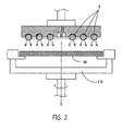
- FIG. 2 is a cross sectional view a heating apparatus using the filament lamp of FIG. 1 ;
- FIG. 3 is a view illustrating the relationship between a workpiece and the filament lamps ofthe heating apparatus of FIG. 2 ;
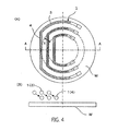
- FIG. 4 is a view showing a state which has been rotated to 90° from a state of FIG. 3 ;
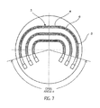
- FIG. 5 illustrates another embodiment of the present invention
- FIG. 6 is a view showing a modification ofthe embodiment of FIG. 5 ;
- FIG. 7 illustrates a further embodiment ofthe present invention
- FIG. 8 is a graph showing the effects of the present invention.
- FIG. 9 is a plan view of a conventional technique
- FIG. 10 is a plan view of another conventional technique.
- FIG. 11 is a view illustrating problems ofthe conventional technique of FIG. 9 .
- FIG. 1 is a partial plan view of a heating apparatus having filament lamps 1 for heating according to the present invention.
- FIG. 2 is a cross sectional view ofthe heating apparatus.
- the filament lamps 1 are lamps which radiate light onto a disk-shaped workpiece W to heat it.
- the filament lamps 1 are concentrically arranged above the workpiece W.
- the workpiece W is supported on a support 10.
- the filament lamps 1 and the workpiece W are rotated relative to each other by rotating the support 10, while the filament lamps 1 radiate light onto the workpiece W and heat it.
- the workpiece W has been illustrated as rotating, it may be configured such that the filament lamps 1 rotates and the workpiece W is stationary.
- the arrangement relationship between the workpiece W and the filament lamp 1 may be inverted, in other words, the filament lamps 1 may be disposed below the workpiece W so that the workpiece W is heated in such a way that light is radiated onto a lower surface of the workpiece W.
- each filament lamp 1 has a filament 2 therein.
- the filament lamp 1 includes an arc-shaped emitting part 3 and an auxiliary emitting part 4 which is integrally provided in a medial portion of the arc-shaped emitting part 3.
- Each emitting part 3 has an arc shape having a rotating center O ofthe workpiece W as its center.
- the auxiliary emitting part 4 which is continuously provided in the medial portion ofthe arc-shaped emitting part 3 has a linear shape.
- the auxiliary emitting part 4 is disposed inside a circle extending along the arc-shaped emitting part 3 and extends in such a way that the auxiliary emitting part 4 crosses over the circle. Due to this structure, in the heating apparatus having the filament lamps 1, an annular area X of the workpiece W that is defined between the adjacent two filament lamps 1 passes below the corresponding auxiliary emitting part 4 when the workpiece W rotates.
- the auxiliary emitting part 4 has been illustrated as being linear, the shape of the auxiliary emitting part 4 is not limited to a linear shape.
- the auxiliary emitting part 4 may have an arc shape having a different curvature radius from that of the arc-shaped emitting part 3. That is, the auxiliary emitting part 4 can have any shape, so long as it is present inside the circle extending along the arc-shaped emitting part 3 and the area X defined on the workpiece W between the adjacent filament lamps 1 can pass just below the auxiliary emitting part 4 when the workpiece W rotates.
- FIGS. 3 and 4 are views illustrating the above-mentioned operation in different points of view.
- a state which was rotated to 90° from a state of FIG. 3 is illustrated in FIG. 4 , wherein FIG. 4 shows that only the filament lamps 1 have been rotated 90°.
- the arc-shaped emitting parts 3 of the filament lamps 1 are disposed at comparatively radially outer portions of the workpiece W, while in the case of FIG. 4 , the auxiliary emitting parts 4 of the filament lamps 1 are disposed at comparatively radially inner portions of the workpiece W. That is, when the workpiece W rotates, the filament lamps 1 act as if they move inwards. Thereby, all areas ofthe workpiece W with respect to the radial direction can uniformly pass below the filament lamp 1.
- the auxiliary emitting part 4 of each filament lamp 1 is preferably configured such that only the annular area X defined on the workpiece W between the arc-shaped emitting parts 3 of the adjacent two filament lamps 1 passes just below the auxiliary emitting part 4 of one ofthe filament lamps 1 that is disposed at an outer portion.
- an area on the workpiece W that has passed just below the arc-shaped emitting part 3 of one of the filament lamps 1 be prevented from also passing just below the auxiliary emitting part 4 ofthe adjacent outer filament lamp 1. This is because that area that has been heated by the arc-shaped emitting part 3 must be restricted from being heated once more by the auxiliary emitting part 4 ofthe adjacent outer filament lamp 1.
- the auxiliary emitting part 4 of one of the filament lamps 1, for example, the auxiliary emitting part 4b of the filament lamp 1b is disposed inside the circle extending along the arc-shaped emitting part 3b of the filament lamp 1b but does not enter the circle extending along the arc-shaped emitting part 3a of the adjacent inner filament lamp 1a. Thanks to this structure, an area of the workpiece W that is disposed just below the arc-shaped emitting part 3a ofthe inner filament lamp 1a can be prevented from passing below the auxiliary emitting part 4b of the adjacent filament lamp 1b. Thereby, an area of the workpiece W can be prevented from being doubly heated by the arc-shaped emitting part 1a and the auxiliary emitting part 4b.
- each filament lamp 1 has a partially open ring shape, rather than having a complete-ring shape that covers the entirety of a circumferential area ofthe workpiece W.
- Each filament lamp 1 includes a rod part and caps 5. Because the filament lamp 1 has a partially open ring shape, wiring work for supply of power which is associated with the caps 5 can be facilitated.
- an open angle ⁇ between opposite ends 2a ofthe filament 2 on the rotating center O of the workpiece W be the same in all the filament lamps 1.
- circumferential lengths of the arc-shaped emitting parts 3 are increased at a predetermined ratio from the center to the perimeter, whereby a rate at which the filament 2 radiates light onto unit circumferential area of the workpiece W can be uniform.
- auxiliary emitting part 4 has been illustrated as being provided in the medial portion of the arc-shaped emitting part 3, an auxiliary emitting part 4 may extend from one end of an arc-shaped emitting part 3, as illustrated in another embodiment of FIG. 5 .
- the auxiliary emitting part 4 is integrally connected to a first end of the arc-shaped emitting part 3 ofthe filament lamp 1.
- Caps 5 are respectively provided on a second end ofthe arc-shaped emitting part 3 and an end ofthe auxiliary emitting part 4.
- the auxiliary emitting part 4 of the filament lamp 1 is disposed inside a circle extending along the arc-shaped emitting part 3 and extends in such a way that the auxiliary emitting part 4 crosses over the circle.
- the auxiliary emitting part 4 of one of the filament lamps 1, for example, the auxiliary emitting part 4b of the filament lamp 1b do not enter the circle extending along the arc-shaped emitting part 3 a ofthe adjacent inner filament lamp 1a.
- the auxiliary emitting part 4b be prevented from extending to the outside of the circle extending along the arc-shaped emitting part 3b.
- the auxiliary emitting part 4b of the filament lamp 1b functions to radiate light onto an annular area X1 defined between the arc-shaped emitting part 3b ofthe filament lamp 1b and the arc-shaped emitting part 3a ofthe adjacent inner filament lamp 1a. If the auxiliary emitting part 4b extends to the outside of the circle extending along the arc-shaped emitting part 3b, it enters an annular area X2 between the arc-shaped emitting part 3b of the filament lamp 1b and the arc-shaped emitting part 3c of the adjacent outer filament lamp 1c.
- the annular area X2 is doubly heated, because the annular area X2 is originally governed by the auxiliary emitting part 4c of the filament lamp 1c. Therefore, to avoid this problem, the auxiliary emitting part 4b is preferably prevented from extending to the outside of the circle extending along the arc-shaped emitting part 3b.
- each auxiliary emitting part 4 has been illustrated as twice crossing over the corresponding annular area X defined between the shaped emitting parts 3 of the adjacent filament lamps 1, wherein the annular area X is heated twice by the corresponding auxiliary emitting part 4 while the workpiece W makes one revolution.
- the auxiliary emitting part 4 may be configured such that it extends to a half of the annular area X so that light is radiated once onto the annular area X when the workpiece W makes one revolution.
- each filament lamp 1 may be integrally formed to be round.
- a light emitting tube ofthe filament lamp 1 may be damaged by stress concentration. To avoid such a stress concentration phenomenon, it is more preferable that the filament lamp 1 be formed to be round.
- a numerical example of the heating apparatus with three filament lamps 3 having the shape of FIG. 1 is as follows.
- Arc-shaped emitting part Radius of 50 mm (diameter of 100 mm) on rotating center O
- Auxiliary emitting part 80 mm
- Arc-shaped emitting part Radius of 100 mm (diameter of 200 mm) on rotating center O
- Auxiliary emitting part 120 mm
- Arc-shaped emitting part Radius of 150 mm (diameter of 300 mm) on rotating center O
- Auxiliary emitting part 160 mm
- FIG. 8 Simulations of heating performance of the heating apparatuses having the above-stated conditions were performed, and the results thereof are illustrated in FIG. 8 .
- the solid line illustrates the embodiment of the present invention
- the dotted line shows the conventional embodiment.
- relative intensities of heating are comparatively high on areas between the arc-shaped emitting parts 3 of the filament lamps 1. That is, it can be understood that the temperature uniformity with respect to the radial direction be markedly improved. Further, relative intensity of heating is markedly enhanced even on an area inside the innermost filament lamp 1a.
- a filament lamp for heating includes an arc-shaped emitting part which circumferentially extends and radiates light onto a workpiece while rotating relative to the workpiece, and an auxiliary emitting part which is disposed inside a circle extending along the arc-shaped emitting part and extends in a direction crossing the circle. Furthermore, in a heating apparatus according to the present invention, a plurality of filament lamps that have the above structure are concentrically arranged. An area defined on the workpiece between the adjacent arc-shaped emitting parts passes just below the corresponding auxiliary emitting part so that the intensity of radiation on this area is increased, whereby the intensity of radiation on the workpiece with respect to the radial direction can become uniform. As a result, the temperature uniformity can be markedly enhanced.
Landscapes
- Engineering & Computer Science (AREA)
- Manufacturing & Machinery (AREA)
- General Engineering & Computer Science (AREA)
- Resistance Heating (AREA)
- Control Of Resistance Heating (AREA)
- Health & Medical Sciences (AREA)
- Toxicology (AREA)
Abstract
Description
- The present invention relates generally to filament lamps for heating disk-shaped workpieces and, more particularly, to a filament lamp for heating a semiconductor wafer in such a way that the filament lamp and the semiconductor wafer rotate relative to each other.
- As is well known to those skilled in the art, filament lamps are widely used as heating sources for heat treatment such as annealing, oxidation, diffusion when forming a film such as an oxide film, a metal film or a semiconductor film on a substrate, e.g. a semiconductor wafer, or the like.
- A heating apparatus using such a heating source is generally configured such that the heating source heats a workpiece when the workpiece is rotating. This technique was disclosed in Japanese Patent Application Publication No.
2010-086985 - However, the conventional heating apparatus uses a linear tubular lamp, which may easily cause nonuniformity in light radiation between a central portion and a perimeter portion of a workpiece.
FIG. 9 shows this nonuniformity phenomenon. When a lineartubular lamp 20 radiates light onto a workpiece W that is rotating, a light radiation rate is different between a central portion A and a perimeter portion B of the workpiece W. As a result, the central portion A of the workpiece W is heated to a high temperature, while the perimeter portion B thereof is heated to a lower temperature. As such, if the overall area of the workpiece W is not uniformly heated, it is impossible to reliably and uniformly process the workpiece. This causes a defective product. - In an effort to overcome the above problem, a heating source having a plurality of annular lamps which face a rotating workpiece was proposed in Japanese Patent Application Publication No.
1999-176389 FIG. 10 . Referring toFIG. 10 , theannular lamps annular lamps - However, as shown in
FIG. 11 , even though the annular lamps that are concentrically arranged on the same plane radiate light onto the workpiece, because areas of the workpiece that correspond to spaces between the lamps do not pass just below the lamps, radiation is applied to these areas with less intensity than it is to those of areas of the workpiece that are disposed just below the lamps. As a result, heating temperature with respect to the radial direction of the workpiece becomes non-uniform. - Furthermore, this conventional technique requires the several annular lamps to be arranged on the same plane, thus making the electrical wiring for the lamps very complex.
- [Prior Art Documents]
- Japanese Patent Application Publication No.
2010-086985 - Japanese Patent Application Publication No.
1999-176389 - Accordingly, the present invention has been made keeping in mind the above problems occurring in the prior art, and an object ofthe present invention is to provide a filament lamp for heating a disk-shaped workpiece in such a way that the filament lamp radiates light onto the disk-shaped workpiece while the filament lamp and the disk-shaped workpiece rotate relative to each other, and a heating apparatus using the filament lamp, and, particularly, to a structure that enables heating temperature to be maintained uniformly on a central portion and a perimeter portion of the disk-shaped workpiece so that the workpiece can be uniformly heated without separately controlling the temperature of the filament lamp.
- In order to accomplish the above object, in an aspect, the present invention provides a filament lamp for heating a disk-shaped workpiece in such a way that the filament lamp rotates relative to the disk-shaped workpiece and radiates light thereonto, the filament lamp including: an arc-shaped emitting part extending in a circumferential direction of the relative rotation; and an auxiliary emitting part disposed inside a circle extending along the arc-shaped emitting part and extending from the arc-shaped emitting part in a direction crossing the circle.
- The auxiliary emitting part may have a linear shape.
- The auxiliary emitting part may be provided in a medial portion of the arc-shaped emitting part.
- The auxiliary emitting part may be integrally connected to an end of the arc-shaped emitting part.
- The arc-shaped emitting part and the auxiliary emitting part may be integrally formed to be round.
- In a filament lamp for heating a disk-shaped workpiece according to the present invention, arc-shaped emitting parts ofthe filament lamps uniformly heat areas ofthe workpiece with respect to the circumferential direction. In addition, areas of the workpiece that correspond to spaces between the arc-shaped emitting parts of the filament lamps pass just below corresponding auxiliary emitting parts of the filament lamps when the filament lamps and the workpiece rotate relative to each other. That is, all areas of the workpiece with respect to the radial direction can pass just below the filament lamps. As a result, heating temperature of the areas ofthe workpiece with respect to the radial direction can also become uniform.
- Moreover, because each filament lamp includes the arc-shaped emitting part and the auxiliary emitting part, wiring work can be facilitated using space between the opposite ends of the filament lamp.
- The above and other objects, features and advantages of the present invention will be more clearly understood from the following detailed description taken in conjunction with the accompanying drawings, in which:
-
FIG. 1 illustrates filament lamps for heating, according to an embodiment of the present invention; -
FIG. 2 is a cross sectional view a heating apparatus using the filament lamp ofFIG. 1 ; -
FIG. 3 is a view illustrating the relationship between a workpiece and the filament lamps ofthe heating apparatus ofFIG. 2 ; -
FIG. 4 is a view showing a state which has been rotated to 90° from a state ofFIG. 3 ; -
FIG. 5 illustrates another embodiment of the present invention; -
FIG. 6 is a view showing a modification ofthe embodiment ofFIG. 5 ; -
FIG. 7 illustrates a further embodiment ofthe present invention; -
FIG. 8 is a graph showing the effects of the present invention; -
FIG. 9 is a plan view of a conventional technique; -
FIG. 10 is a plan view of another conventional technique; and -
FIG. 11 is a view illustrating problems ofthe conventional technique ofFIG. 9 . - Reference now should be made to the drawings, throughout which the same reference numerals are used to designate the same or similar components.
-
FIG. 1 is a partial plan view of a heating apparatus havingfilament lamps 1 for heating according to the present invention.FIG. 2 is a cross sectional view ofthe heating apparatus. - As shown in
FIGS. 1 and2 , thefilament lamps 1 are lamps which radiate light onto a disk-shaped workpiece W to heat it. Thefilament lamps 1 are concentrically arranged above the workpiece W. - The workpiece W is supported on a
support 10. Thefilament lamps 1 and the workpiece W are rotated relative to each other by rotating thesupport 10, while thefilament lamps 1 radiate light onto the workpiece W and heat it. - In this embodiment, although the workpiece W has been illustrated as rotating, it may be configured such that the
filament lamps 1 rotates and the workpiece W is stationary. - The arrangement relationship between the workpiece W and the
filament lamp 1 may be inverted, in other words, thefilament lamps 1 may be disposed below the workpiece W so that the workpiece W is heated in such a way that light is radiated onto a lower surface of the workpiece W. - As shown in
FIG. 1 , eachfilament lamp 1 has afilament 2 therein. Thefilament lamp 1 includes an arc-shaped emitting part 3 and anauxiliary emitting part 4 which is integrally provided in a medial portion of the arc-shapedemitting part 3. - Each emitting
part 3 has an arc shape having a rotating center O ofthe workpiece W as its center. In the embodiment ofFIG. 1 , theauxiliary emitting part 4 which is continuously provided in the medial portion ofthe arc-shaped emitting part 3 has a linear shape. - The
auxiliary emitting part 4 is disposed inside a circle extending along the arc-shaped emittingpart 3 and extends in such a way that the auxiliary emittingpart 4 crosses over the circle. Due to this structure, in the heating apparatus having thefilament lamps 1, an annular area X of the workpiece W that is defined between the adjacent twofilament lamps 1 passes below the correspondingauxiliary emitting part 4 when the workpiece W rotates. - Therefore, all areas ofthe workpiece W can pass just below the
filament lamps 1 so that non-uniformity in temperature of the workpiece W with respect to the radial direction can be prevented. - Furthermore, although the
auxiliary emitting part 4 has been illustrated as being linear, the shape of theauxiliary emitting part 4 is not limited to a linear shape. For example, theauxiliary emitting part 4 may have an arc shape having a different curvature radius from that of the arc-shaped emittingpart 3. That is, theauxiliary emitting part 4 can have any shape, so long as it is present inside the circle extending along the arc-shaped emittingpart 3 and the area X defined on the workpiece W between theadjacent filament lamps 1 can pass just below theauxiliary emitting part 4 when the workpiece W rotates. -
FIGS. 3 and4 are views illustrating the above-mentioned operation in different points of view. With regard to these drawings, a state which was rotated to 90° from a state ofFIG. 3 is illustrated inFIG. 4 , whereinFIG. 4 shows that only thefilament lamps 1 have been rotated 90°. - Based on line A-A, in the case of
FIG. 3 , the arc-shaped emittingparts 3 of thefilament lamps 1 are disposed at comparatively radially outer portions of the workpiece W, while in the case ofFIG. 4 , theauxiliary emitting parts 4 of thefilament lamps 1 are disposed at comparatively radially inner portions of the workpiece W. That is, when the workpiece W rotates, thefilament lamps 1 act as if they move inwards. Thereby, all areas ofthe workpiece W with respect to the radial direction can uniformly pass below thefilament lamp 1. - Referring again to
FIG. 1 , theauxiliary emitting part 4 of eachfilament lamp 1 is preferably configured such that only the annular area X defined on the workpiece W between the arc-shaped emittingparts 3 of the adjacent twofilament lamps 1 passes just below theauxiliary emitting part 4 of oneofthe filament lamps 1 that is disposed at an outer portion. In other words, it is preferable that an area on the workpiece W that has passed just below the arc-shaped emittingpart 3 of one of thefilament lamps 1 be prevented from also passing just below theauxiliary emitting part 4 ofthe adjacentouter filament lamp 1. This is because that area that has been heated by the arc-shaped emittingpart 3 must be restricted from being heated once more by theauxiliary emitting part 4 ofthe adjacentouter filament lamp 1. - The above-mentioned arrangement results from the following construction.
- In detail, the
auxiliary emitting part 4 of one of thefilament lamps 1, for example, theauxiliary emitting part 4b of thefilament lamp 1b, is disposed inside the circle extending along the arc-shaped emittingpart 3b of thefilament lamp 1b but does not enter the circle extending along the arc-shaped emittingpart 3a of the adjacentinner filament lamp 1a. Thanks to this structure, an area of the workpiece W that is disposed just below the arc-shaped emittingpart 3a oftheinner filament lamp 1a can be prevented from passing below theauxiliary emitting part 4b of theadjacent filament lamp 1b. Thereby, an area of the workpiece W can be prevented from being doubly heated by the arc-shaped emittingpart 1a and theauxiliary emitting part 4b. - Furthermore, as shown in
FIG. 1 , eachfilament lamp 1 has a partially open ring shape, rather than having a complete-ring shape that covers the entirety of a circumferential area ofthe workpiece W. - Each
filament lamp 1 includes a rod part and caps 5. Because thefilament lamp 1 has a partially open ring shape, wiring work for supply of power which is associated with thecaps 5 can be facilitated. - Further, in this case, it is preferable that an open angle α between opposite ends 2a ofthe
filament 2 on the rotating center O of the workpiece W be the same in all thefilament lamps 1. - Due to this structure, circumferential lengths of the arc-shaped emitting
parts 3 are increased at a predetermined ratio from the center to the perimeter, whereby a rate at which thefilament 2 radiates light onto unit circumferential area of the workpiece W can be uniform. - In the embodiment of
FIG. 1 , although theauxiliary emitting part 4 has been illustrated as being provided in the medial portion of the arc-shaped emittingpart 3, anauxiliary emitting part 4 may extend from one end of an arc-shaped emittingpart 3, as illustrated in another embodiment ofFIG. 5 . - In detail, the
auxiliary emitting part 4 is integrally connected to a first end of the arc-shaped emittingpart 3ofthe filament lamp 1.Caps 5 are respectively provided on a second end ofthe arc-shaped emittingpart 3 and an end ofthe auxiliary emittingpart 4. - In this embodiment, also, the
auxiliary emitting part 4 of thefilament lamp 1 is disposed inside a circle extending along the arc-shaped emittingpart 3 and extends in such a way that theauxiliary emitting part 4 crosses over the circle. - Further, in the same manner as the embodiment of
FIG. 1 , it is preferable that theauxiliary emitting part 4 of one of thefilament lamps 1, for example, theauxiliary emitting part 4b of thefilament lamp 1b, do not enter the circle extending along the arc-shaped emittingpart 3 a ofthe adjacentinner filament lamp 1a. - In addition, it is preferable that the
auxiliary emitting part 4b be prevented from extending to the outside of the circle extending along the arc-shaped emittingpart 3b. Theauxiliary emitting part 4b of thefilament lamp 1b functions to radiate light onto an annular area X1 defined between the arc-shaped emittingpart 3b ofthefilament lamp 1b and the arc-shaped emittingpart 3a ofthe adjacentinner filament lamp 1a. If theauxiliary emitting part 4b extends to the outside of the circle extending along the arc-shaped emittingpart 3b, it enters an annular area X2 between the arc-shaped emittingpart 3b of thefilament lamp 1b and the arc-shaped emittingpart 3c of the adjacentouter filament lamp 1c. In this case, the annular area X2 is doubly heated, because the annular area X2 is originally governed by theauxiliary emitting part 4c of thefilament lamp 1c. Therefore, to avoid this problem, theauxiliary emitting part 4b is preferably prevented from extending to the outside of the circle extending along the arc-shaped emittingpart 3b. - In the embodiment of
FIG. 5 , each auxiliary emittingpart 4 has been illustrated as twice crossing over the corresponding annular area X defined between the shaped emittingparts 3 of theadjacent filament lamps 1, wherein the annular area X is heated twice by the correspondingauxiliary emitting part 4 while the workpiece W makes one revolution. On the other hand, as shown inFIG. 6 , depending on the extent oftemperature uniformity, theauxiliary emitting part 4 may be configured such that it extends to a half of the annular area X so that light is radiated once onto the annular area X when the workpiece W makes one revolution. - Furthermore, referring to
FIG. 7 , as designated byreference numeral 6, the arc-shaped emittingpart 3 and theauxiliary emitting part 4 of eachfilament lamp 1 may be integrally formed to be round. In the case of an angular shape, a light emitting tube ofthefilament lamp 1 may be damaged by stress concentration. To avoid such a stress concentration phenomenon, it is more preferable that thefilament lamp 1 be formed to be round. - A numerical example of the heating apparatus with three
filament lamps 3 having the shape ofFIG. 1 is as follows. - <
Filament lamp 1a > - Light emitting tube of filament lamp: φ 10 mm
- Arc-shaped emitting part: Radius of 50 mm (diameter of 100 mm) on rotating center O
- Auxiliary emitting part : 80 mm
- Open angle α: 150°
- Lighting conditions: Maximum output 200V-800W, controlled depending on temperature ofworkpiece
- <
Filament lamp 1b > - Arc-shaped emitting part: Radius of 100 mm (diameter of 200 mm) on rotating center O
- Auxiliary emitting part : 120 mm
- Open angle α: 150°
- Lighting conditions: Maximum output 200V-1500W, controlled depending on temperature ofworkpiece
- <
Filament lamp 1c > - Arc-shaped emitting part: Radius of 150 mm (diameter of 300 mm) on rotating center O
- Auxiliary emitting part : 160 mm
- Open angle α: 150°
- Lighting conditions: Maximum output 200V-2200W, controlled depending on temperature ofworkpiece
- On the other hand, a numerical example ofthe conventional heating apparatus with three
filament lamps FIG. 10 is as follows. - <
Filament lamp 30> - Light emitting tube of filament lamp: φ 10 mm
- Annular filament lamp of φ 100 mm
- Lighting conditions: Maximum output 200V-800W, controlled depending on temperature ofworkpiece
- <
Filament lamp 31> - Annular filament lamp of φ 200 mm
- Lighting conditions: Maximum output 200V-1500W, controlled depending on temperature ofworkpiece
- <
Filament lamp 32> - Annular filament lamp of φ 300 mm
- Lighting conditions: Maximum output 200V-2200W, controlled depending on temperature ofworkpiece
- Simulations of heating performance of the heating apparatuses having the above-stated conditions were performed, and the results thereof are illustrated in
FIG. 8 . In the drawing, the solid line illustrates the embodiment of the present invention, and the dotted line shows the conventional embodiment. - Referring to the dotted line showing the conventional embodiment, relative intensities of heating is high on areas just below the
lamps lamps innermost lamp 30 is very high. - On the other hand, in the present invention, as shown by the solid line, relative intensities of heating are comparatively high on areas between the arc-shaped emitting
parts 3 of thefilament lamps 1. That is, it can be understood that the temperature uniformity with respect to the radial direction be markedly improved. Further, relative intensity of heating is markedly enhanced even on an area inside theinnermost filament lamp 1a. - These effects of the present invention result from the fact that the
auxiliary emitting parts 4 which integrally extend from the respective arc-shaped emittingparts 3 are present inside the corresponding circles extending along the arc-shaped emittingparts 3 so that the areas defined on the workpiece W among thefilament lamps 1 are radiated by theauxiliary emitting parts 4, and the area inside theinnermost filament lamp 1a is radiated by theauxiliary emitting part 4a. - As described above, a filament lamp for heating according to the present invention includes an arc-shaped emitting part which circumferentially extends and radiates light onto a workpiece while rotating relative to the workpiece, and an auxiliary emitting part which is disposed inside a circle extending along the arc-shaped emitting part and extends in a direction crossing the circle. Furthermore, in a heating apparatus according to the present invention, a plurality of filament lamps that have the above structure are concentrically arranged. An area defined on the workpiece between the adjacent arc-shaped emitting parts passes just below the corresponding auxiliary emitting part so that the intensity of radiation on this area is increased, whereby the intensity of radiation on the workpiece with respect to the radial direction can become uniform. As a result, the temperature uniformity can be markedly enhanced.
- Although the preferred embodiments of the present invention have been dis closed for illustrative purposes, those skilled in the art will appreciate that various modifications, additions and substitutions are possible, without departing from the scope and spirit of the invention as disclosed in the accompanying claims.
Claims (5)
- A filament lamp (1) for heating a disk-shaped workpiece (W) in such a way that the filament lamp (1) radiates light onto the disk-shaped workpiece (W) while the filament lamp (1) and the disk-shaped workpiece (W) rotate relative to each other, the filament lamp (1) comprising:an arc-shaped emitting part (3) extending in a circumferential direction of the relative rotation; andan auxiliary emitting part (4) disposed inside a circle extending along the arc-shaped emitting part (3) and extending from the arc-shaped emitting part (3) in a direction crossing the circle.
- The filament lamp (1) as set forth in claim 1, wherein the auxiliary emitting part (4) has a linear shape.
- The filament lamp (1) as set forth in claim 1 or 2, wherein the auxiliary emitting part (4) is provided in a medial portion ofthe arc-shaped emitting part (3).
- The filament lamp (1) as set forth in claim 1 or 2, wherein the auxiliary emitting part (4) is integrally connected to an end ofthe arc-shaped emitting part (3).
- The filament lamp (1) as set forth in claim 1 or 2, wherein the arc-shaped emitting part (3) and the auxiliary emitting part (4) are integrally formed to be round.
Applications Claiming Priority (1)
| Application Number | Priority Date | Filing Date | Title |
|---|---|---|---|
| JP2012219303A JP5652455B2 (en) | 2012-10-01 | 2012-10-01 | Filament lamp for heating |
Publications (2)
| Publication Number | Publication Date |
|---|---|
| EP2713388A2 true EP2713388A2 (en) | 2014-04-02 |
| EP2713388A3 EP2713388A3 (en) | 2017-05-24 |
Family
ID=49035281
Family Applications (1)
| Application Number | Title | Priority Date | Filing Date |
|---|---|---|---|
| EP13179860.5A Withdrawn EP2713388A3 (en) | 2012-10-01 | 2013-08-09 | Filament lamp for heating |
Country Status (5)
| Country | Link |
|---|---|
| US (1) | US9265091B2 (en) |
| EP (1) | EP2713388A3 (en) |
| JP (1) | JP5652455B2 (en) |
| KR (1) | KR101727780B1 (en) |
| TW (1) | TWI545613B (en) |
Cited By (1)
| Publication number | Priority date | Publication date | Assignee | Title |
|---|---|---|---|---|
| CN119776809A (en) * | 2025-03-06 | 2025-04-08 | 蓝河科技(绍兴)有限公司 | Vapor growth equipment with fixed base |
Families Citing this family (7)
| Publication number | Priority date | Publication date | Assignee | Title |
|---|---|---|---|---|
| DE102012106667B3 (en) * | 2012-07-23 | 2013-07-25 | Heraeus Noblelight Gmbh | Device for irradiating a substrate |
| US9748120B2 (en) * | 2013-07-01 | 2017-08-29 | Lam Research Ag | Apparatus for liquid treatment of disc-shaped articles and heating system for use in such apparatus |
| TWI625066B (en) * | 2017-01-06 | 2018-05-21 | Coorstek Kk | Surface heater |
| CN111403316A (en) * | 2020-03-18 | 2020-07-10 | 沈阳拓荆科技有限公司 | Heating system for improving temperature uniformity of silicon wafer |
| JP7667310B2 (en) * | 2021-06-09 | 2025-04-22 | アプライド マテリアルズ インコーポレイテッド | Axisymmetric heating assembly layout using double-ended lamps |
| KR102864317B1 (en) * | 2023-04-11 | 2025-09-25 | 대영전기 주식회사 | Apparatus for manufacturing laminated core of motor with hybrid heating process |
| KR102864314B1 (en) * | 2023-04-11 | 2025-09-25 | 대영전기 주식회사 | Apparatus for manufacturing laminated core of motor with lamp heating process |
Citations (2)
| Publication number | Priority date | Publication date | Assignee | Title |
|---|---|---|---|---|
| JPH11176389A (en) | 1997-12-12 | 1999-07-02 | Ushio Inc | Filament lamp for heating wafer and light source for heating |
| JP2010086985A (en) | 2008-09-29 | 2010-04-15 | Hitachi Kokusai Electric Inc | Wafer-processing apparatus |
Family Cites Families (6)
| Publication number | Priority date | Publication date | Assignee | Title |
|---|---|---|---|---|
| US4859832A (en) * | 1986-09-08 | 1989-08-22 | Nikon Corporation | Light radiation apparatus |
| JP4581238B2 (en) * | 2000-12-12 | 2010-11-17 | 株式会社デンソー | Silicon carbide semiconductor manufacturing apparatus and silicon carbide semiconductor manufacturing method using the same |
| JP5378677B2 (en) | 2006-12-15 | 2013-12-25 | 日本碍子株式会社 | Ceramic heater |
| JP2010040718A (en) | 2008-08-04 | 2010-02-18 | Soken Kogyo Kk | Heater, substrate heating apparatus and crystal growth apparatus using them |
| JP5500511B2 (en) * | 2012-04-11 | 2014-05-21 | ウシオ電機株式会社 | Filament lamp for heating |
| DE102012106667B3 (en) * | 2012-07-23 | 2013-07-25 | Heraeus Noblelight Gmbh | Device for irradiating a substrate |
-
2012
- 2012-10-01 JP JP2012219303A patent/JP5652455B2/en active Active
-
2013
- 2013-07-25 KR KR1020130087813A patent/KR101727780B1/en active Active
- 2013-07-26 US US13/952,153 patent/US9265091B2/en active Active
- 2013-08-02 TW TW102127752A patent/TWI545613B/en active
- 2013-08-09 EP EP13179860.5A patent/EP2713388A3/en not_active Withdrawn
Patent Citations (2)
| Publication number | Priority date | Publication date | Assignee | Title |
|---|---|---|---|---|
| JPH11176389A (en) | 1997-12-12 | 1999-07-02 | Ushio Inc | Filament lamp for heating wafer and light source for heating |
| JP2010086985A (en) | 2008-09-29 | 2010-04-15 | Hitachi Kokusai Electric Inc | Wafer-processing apparatus |
Cited By (1)
| Publication number | Priority date | Publication date | Assignee | Title |
|---|---|---|---|---|
| CN119776809A (en) * | 2025-03-06 | 2025-04-08 | 蓝河科技(绍兴)有限公司 | Vapor growth equipment with fixed base |
Also Published As
| Publication number | Publication date |
|---|---|
| JP2014072130A (en) | 2014-04-21 |
| US20140091079A1 (en) | 2014-04-03 |
| US9265091B2 (en) | 2016-02-16 |
| TW201415532A (en) | 2014-04-16 |
| TWI545613B (en) | 2016-08-11 |
| KR101727780B1 (en) | 2017-04-17 |
| KR20140043272A (en) | 2014-04-09 |
| EP2713388A3 (en) | 2017-05-24 |
| JP5652455B2 (en) | 2015-01-14 |
Similar Documents
| Publication | Publication Date | Title |
|---|---|---|
| US9265091B2 (en) | Filament lamp for heating | |
| TWI512884B (en) | Improved edge ring lip | |
| US6081072A (en) | Filament lamp for wafer heating and heating light source | |
| KR102774117B1 (en) | Lamp heating for process chamber | |
| KR101083576B1 (en) | Light irradiation type heating apparatus and light irradiation type heating method | |
| JPH07130678A (en) | Improved radiant heating source with isolated optical zones | |
| US10455642B2 (en) | Rapid thermal processing chamber with linear control lamps | |
| KR101620775B1 (en) | Device for irradiating a substrate | |
| EP2105948B1 (en) | Filament lamp | |
| JP2012140684A (en) | Vacuum treatment apparatus | |
| KR101533148B1 (en) | Filament lamp for heating and heating apparatus | |
| JP2009212185A (en) | Semiconductor manufacturing apparatus | |
| US6718127B2 (en) | Heating device of the light irradiation type | |
| KR20150066472A (en) | Apparatus and method for uniform irradiation using secondary irradiant energy from a single light source | |
| KR20020028824A (en) | Light illuminating type heating processing apparatus and method therefor | |
| JPS60175431A (en) | Heat treating apparatus | |
| KR101057302B1 (en) | Filament lamp | |
| JP2009164376A (en) | Heat treatment apparatus | |
| WO2024157579A1 (en) | Light heating device | |
| JP2012222057A (en) | Heat treatment apparatus | |
| JPS63260127A (en) | Light irradiation apparatus | |
| JP2002343733A (en) | Heat treatment equipment |
Legal Events
| Date | Code | Title | Description |
|---|---|---|---|
| PUAI | Public reference made under article 153(3) epc to a published international application that has entered the european phase |
Free format text: ORIGINAL CODE: 0009012 |
|
| AK | Designated contracting states |
Kind code of ref document: A2 Designated state(s): AL AT BE BG CH CY CZ DE DK EE ES FI FR GB GR HR HU IE IS IT LI LT LU LV MC MK MT NL NO PL PT RO RS SE SI SK SM TR |
|
| AX | Request for extension of the european patent |
Extension state: BA ME |
|
| PUAL | Search report despatched |
Free format text: ORIGINAL CODE: 0009013 |
|
| AK | Designated contracting states |
Kind code of ref document: A3 Designated state(s): AL AT BE BG CH CY CZ DE DK EE ES FI FR GB GR HR HU IE IS IT LI LT LU LV MC MK MT NL NO PL PT RO RS SE SI SK SM TR |
|
| AX | Request for extension of the european patent |
Extension state: BA ME |
|
| RIC1 | Information provided on ipc code assigned before grant |
Ipc: H05B 3/00 20060101ALI20170418BHEP Ipc: H01L 21/67 20060101AFI20170418BHEP |
|
| STAA | Information on the status of an ep patent application or granted ep patent |
Free format text: STATUS: REQUEST FOR EXAMINATION WAS MADE |
|
| 17P | Request for examination filed |
Effective date: 20171124 |
|
| RBV | Designated contracting states (corrected) |
Designated state(s): AL AT BE BG CH CY CZ DE DK EE ES FI FR GB GR HR HU IE IS IT LI LT LU LV MC MK MT NL NO PL PT RO RS SE SI SK SM TR |
|
| STAA | Information on the status of an ep patent application or granted ep patent |
Free format text: STATUS: EXAMINATION IS IN PROGRESS |
|
| 17Q | First examination report despatched |
Effective date: 20200123 |
|
| GRAP | Despatch of communication of intention to grant a patent |
Free format text: ORIGINAL CODE: EPIDOSNIGR1 |
|
| STAA | Information on the status of an ep patent application or granted ep patent |
Free format text: STATUS: GRANT OF PATENT IS INTENDED |
|
| INTG | Intention to grant announced |
Effective date: 20210309 |
|
| STAA | Information on the status of an ep patent application or granted ep patent |
Free format text: STATUS: THE APPLICATION IS DEEMED TO BE WITHDRAWN |
|
| 18D | Application deemed to be withdrawn |
Effective date: 20210720 |