EP2713053A1 - Scroll compressor - Google Patents
Scroll compressor Download PDFInfo
- Publication number
- EP2713053A1 EP2713053A1 EP12773817.7A EP12773817A EP2713053A1 EP 2713053 A1 EP2713053 A1 EP 2713053A1 EP 12773817 A EP12773817 A EP 12773817A EP 2713053 A1 EP2713053 A1 EP 2713053A1
- Authority
- EP
- European Patent Office
- Prior art keywords
- bushing
- scroll member
- radial bearing
- balance weight
- peripheral surface
- Prior art date
- Legal status (The legal status is an assumption and is not a legal conclusion. Google has not performed a legal analysis and makes no representation as to the accuracy of the status listed.)
- Granted
Links
Images



Classifications
-
- F—MECHANICAL ENGINEERING; LIGHTING; HEATING; WEAPONS; BLASTING
- F01—MACHINES OR ENGINES IN GENERAL; ENGINE PLANTS IN GENERAL; STEAM ENGINES
- F01C—ROTARY-PISTON OR OSCILLATING-PISTON MACHINES OR ENGINES
- F01C21/00—Component parts, details or accessories not provided for in groups F01C1/00 - F01C20/00
- F01C21/02—Arrangements of bearings
-
- F—MECHANICAL ENGINEERING; LIGHTING; HEATING; WEAPONS; BLASTING
- F04—POSITIVE - DISPLACEMENT MACHINES FOR LIQUIDS; PUMPS FOR LIQUIDS OR ELASTIC FLUIDS
- F04C—ROTARY-PISTON, OR OSCILLATING-PISTON, POSITIVE-DISPLACEMENT MACHINES FOR LIQUIDS; ROTARY-PISTON, OR OSCILLATING-PISTON, POSITIVE-DISPLACEMENT PUMPS
- F04C18/00—Rotary-piston pumps specially adapted for elastic fluids
- F04C18/02—Rotary-piston pumps specially adapted for elastic fluids of arcuate-engagement type, i.e. with circular translatory movement of co-operating members, each member having the same number of teeth or tooth-equivalents
- F04C18/0207—Rotary-piston pumps specially adapted for elastic fluids of arcuate-engagement type, i.e. with circular translatory movement of co-operating members, each member having the same number of teeth or tooth-equivalents both members having co-operating elements in spiral form
- F04C18/0246—Details concerning the involute wraps or their base, e.g. geometry
- F04C18/0253—Details concerning the base
-
- F—MECHANICAL ENGINEERING; LIGHTING; HEATING; WEAPONS; BLASTING
- F04—POSITIVE - DISPLACEMENT MACHINES FOR LIQUIDS; PUMPS FOR LIQUIDS OR ELASTIC FLUIDS
- F04C—ROTARY-PISTON, OR OSCILLATING-PISTON, POSITIVE-DISPLACEMENT MACHINES FOR LIQUIDS; ROTARY-PISTON, OR OSCILLATING-PISTON, POSITIVE-DISPLACEMENT PUMPS
- F04C29/00—Component parts, details or accessories of pumps or pumping installations, not provided for in groups F04C18/00 - F04C28/00
- F04C29/0042—Driving elements, brakes, couplings, transmissions specially adapted for pumps
- F04C29/005—Means for transmitting movement from the prime mover to driven parts of the pump, e.g. clutches, couplings, transmissions
- F04C29/0057—Means for transmitting movement from the prime mover to driven parts of the pump, e.g. clutches, couplings, transmissions for eccentric movement
-
- F—MECHANICAL ENGINEERING; LIGHTING; HEATING; WEAPONS; BLASTING
- F04—POSITIVE - DISPLACEMENT MACHINES FOR LIQUIDS; PUMPS FOR LIQUIDS OR ELASTIC FLUIDS
- F04C—ROTARY-PISTON, OR OSCILLATING-PISTON, POSITIVE-DISPLACEMENT MACHINES FOR LIQUIDS; ROTARY-PISTON, OR OSCILLATING-PISTON, POSITIVE-DISPLACEMENT PUMPS
- F04C2240/00—Components
- F04C2240/50—Bearings
- F04C2240/51—Bearings for cantilever assemblies
-
- F—MECHANICAL ENGINEERING; LIGHTING; HEATING; WEAPONS; BLASTING
- F04—POSITIVE - DISPLACEMENT MACHINES FOR LIQUIDS; PUMPS FOR LIQUIDS OR ELASTIC FLUIDS
- F04C—ROTARY-PISTON, OR OSCILLATING-PISTON, POSITIVE-DISPLACEMENT MACHINES FOR LIQUIDS; ROTARY-PISTON, OR OSCILLATING-PISTON, POSITIVE-DISPLACEMENT PUMPS
- F04C2240/00—Components
- F04C2240/50—Bearings
- F04C2240/56—Bearing bushings or details thereof
-
- F—MECHANICAL ENGINEERING; LIGHTING; HEATING; WEAPONS; BLASTING
- F04—POSITIVE - DISPLACEMENT MACHINES FOR LIQUIDS; PUMPS FOR LIQUIDS OR ELASTIC FLUIDS
- F04C—ROTARY-PISTON, OR OSCILLATING-PISTON, POSITIVE-DISPLACEMENT MACHINES FOR LIQUIDS; ROTARY-PISTON, OR OSCILLATING-PISTON, POSITIVE-DISPLACEMENT PUMPS
- F04C2240/00—Components
- F04C2240/80—Other components
- F04C2240/807—Balance weight, counterweight
Definitions
- the present invention relates to a scroll-type compressor which is used in a refrigerating cycle of an air conditioning device for a vehicle, and more particularly to a scroll-type compressor having the constitution where an eccentric shaft which is provided to an end portion of a drive shaft is pivotally supported on a boss portion of a revolving scroll member by way of a bushing and a radial bearing.
- a scroll-type compressor includes: a fixed scroll member which has an end plate and a spiral wall formed on the end plate in an erected manner; and a revolving scroll member which is arranged so as to face the fixed scroll member in an opposed manner and has an end plate and a spiral wall formed on the end plate in an erected manner.
- the revolving scroll member is configured such that a boss portion is formed on a back surface of the end plate and an eccentric shaft which is provided to one end of a drive shaft is pivotally supported on the boss portion by way of a radial bearing so that the revolving scroll member is supported in a state where the revolving scroll member performs the rocking rotation (revolving motion) about an axis of the drive shaft.
- the scroll-type compressor disclosed in patent literature 1 is, as shown in Fig. 6 , configured such that a bushing 103 is fitted in a boss portion 102 of a revolving scroll member 101, and the bushing 103 is of a so-called slide-type bushing which is non-rotatable relative to an eccentric shaft 105 provided to one end of a drive shaft 104 and is slightly movable in the radial direction.
- a curved surface portion 106 is formed on the eccentric shaft 105 so that even when the deformation by deflection is generated in the drive shaft 104 due to a compressive force or a centrifugal force of the revolving scroll member 101, the occurrence of a non-uniform contact on a bearing portion is prevented.
- This publication also discloses the constitution where a balance weight 107 is mounted on the drive shaft 104 at a position axially displaced from the bushing 103.
- the scroll-type compressor disclosed in patent literature 2 is, as shown in Fig. 7 , configured such that an eccentric shaft 112 provided to one end of a drive shaft 111 is pivotally supported on a boss portion 117 of a revolving scroll member 115 by way of a bushing 113 and a radial bearing 114, wherein a balance weight 116 is supported on the bushing 113 by being press-fitted on an outer peripheral surface of the bushing 113 so that the balance weight 116 is rotatable together with the bushing 113.
- the balance weight 116 is arranged so as to project over the outer side of the boss portion 117 of the revolving scroll member 115 in a radial direction such that a point of action where a centrifugal force acts on the balance weight 116 is positioned as close as possible to a point of action where a centrifugal force acts on the revolving scroll member 115.
- the scroll-type compressor disclosed in patent literature 3 is, as shown in Fig. 8 , configured such that a bushing 122 with which a balance weight 121 is integrally formed is assembled to an eccentric shaft 124 provided to a distal end of a drive shaft 123, and the bushing 122 is pivotally supported on a boss portion 126 formed on a back surface of a revolving scroll member 125 by way of a radial bearing 127 thus making the revolving scroll member 125 perform the revolving motion.
- the balance weight 121 is arranged so as to project over an outer side of the boss portion 126 of the revolving scroll member 125 in the same manner as patent literature 2, the balance weight 121 is also arranged such that the balance weight 121 further projects toward a side opposite to the revolving scroll member 125 (motor side).
- the scroll-type compressor disclosed in patent literature 3 is designed such that the projecting of the balance weight 121 in the radial direction is suppressed thus preventing the revolving scroll member 125 from becoming large-sized.
- the portion on which the balance weight 107 is mounted is not the bushing 103 but the drive shaft 104. Accordingly, centrifugal forces are cancelled each other and balanced in the compressor as a whole. However, the balance weight 107 does not act so as to cancel a centrifugal force of the revolving scroll member 101 which acts so as to push out the revolving scroll member 101 radially outward.
- the balance weight 116 is formed so as to project over the outside of the boss portion 117 and hence, a rotation prevention mechanism 118 is disposed radially outside the balance weight 116 so as to prevent the interference with the balance weight 116. Accordingly, the revolving scroll member 115 becomes large-sized thus hampering the miniaturization of the compressor. Further, a weight of the revolving scroll member 115 is also increased and hence, there also arises a drawback that it is necessary to make the balance weight 116 large-sized to take a balance with the revolving scroll member 115.
- the balance weight 121 is formed such that the balance weight 121 projects also toward the side opposite to the revolving scroll member 125 (motor side) and hence, a centrifugal force of the balance weight 121 acts on an end portion of the bushing 122 which projects from the radial bearing 127 whereby an axis of the bushing 122 tends to be inclined with respect to an axis of the eccentric shaft 124.
- the scroll-type compressor is designed such that a clearance between the radial bearing 127 and an outer peripheral surface of the bushing 122 is set as small as possible so as to make the radial bearing 127 support a force by which the bushing 122 is inclined.
- a local contact of an inner ring of the bearing exceeds a yield strength thus giving rise to a drawback that flaking occurs.
- the scroll-type compressor is designed such that a clearance between an inner peripheral surface of a radial bearing 24 and an outer peripheral surface of a bushing 23 (a clearance between a roller 24a and an outer peripheral surface of the bushing 23 in the case of the needle bearing) C is made as small as possible (such that the clearance C becomes smaller than a clearance A between the bushing 23 and an eccentric shaft 17).
- a balance weight 32 is mounted on an end portion of the bushing 23 so that the center of gravity of the balance weight 32 is displaced from the center of the eccentric shaft 17 provided to an end portion of a drive shaft 12 and hence, as shown in Fig. 9B , an axis of the bushing 23 is inclined with respect to the axis of the eccentric shaft 17.
- a centrifugal force of the balance weight 32 acts on a revolving scroll member 22 by way of the bushing 23 and the radial bearing 24.
- the present invention has been made in view of the above, and it is a primary object of the present invention to provide a scroll-type compressor which can, even at the high speed rotation, prevent the occurrence of flaking at a contact portion of a radial bearing which is in contact with a bushing while suppressing the increase in rolling resistance of spiral walls of a pair of scroll members. It is another object of the present invention to realize the miniaturization of the compressor. Solution to Problem
- a scroll-type compressor is directed to a scroll-type compressor which includes: a fixed scroll member whose movement in the radial direction with respect to a housing is restricted, the fixed scroll member having an end plate and a spiral wall which is formed on the end plate in an erected manner; a revolving scroll member which is arranged so as to face the fixed scroll member in an opposed manner, the revolving scroll member having an end plate and a spiral wall which is formed on the end plate in an erected manner; a drive shaft which transmits rotational power; an eccentric shaft which is provided to an end portion of the drive shaft at a position offset from an axis of the drive shaft; a radial bearing which is fitted into a boss portion formed on a back surface of the revolving scroll member; a bushing which has an eccentric hole into which the eccentric shaft is inserted, the bushing being fitted on the eccentric shaft by way of the eccentric hole, and the bushing being relatively rotatably supported on the
- an offset load generated in the radial bearing can be decreased and hence, a yield strength of the radial bearing is relatively enhanced whereby the occurrence of flaking which occurs at a contact portion of the radial bearing which is in contact with the outer peripheral surface of the bushing can be suppressed.
- the relationship A/B ⁇ C/D may preferably be established.
- a needle bearing may preferably be used as the radial bearing.
- the needle bearing has a compact shape and is light-weighted, a contact face pressure becomes excessively large when a shaft is brought into contact with the needle bearing in a state that the shaft is inclined with respect to an axis of the bearing and hence, the use of the needle bearing is supposed not to be desirable for supporting an axial load or the inclining of the shaft.
- a local load between the radial bearing and the bushing can be decreased as described above and hence, a yield strength of the radial bearing can be relatively enhanced whereby the needle bearing can sufficiently cope with the supporting of an axial load or the inclining of the shaft as the radial bearing.
- a weight of the bearing can be reduced, and a size of the radial bearing in the radial direction can be also made compact so that the balance weight can be also made light-weighted.
- the needle bearing can be sufficiently used as the radial bearing.
- the revolving scroll member in which the needle bearing is mounted becomes light-weighted, and a weight of the balance weight which is provided for canceling a centrifugal force of the revolving scroll member can be also decreased.
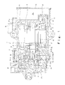
- a scroll-type compressor 1 is an electrically-operated compressor suitable for a refrigerating cycle which uses a refrigerant as a working fluid, wherein, in the inside of a housing 2 which is made of an aluminum alloy, a compression mechanism 3 is arranged on a left side in the drawing, and an electrically-operated motor 4 for driving the compression mechanism 3 is arranged on a right side in the drawing.
- a front side of the compressor 1 is arranged on a right side in the drawing, and a rear side of the compressor is arranged on a left side in the drawing.
- the housing 2 includes: a compression mechanism housing member 2a which houses the compression mechanism 3 therein, an electrically-operated motor housing member 2b which houses the electrically-operated motor 4 for driving the compression mechanism 3 therein; and an inverter housing member 2c which houses an inverter device not shown in the drawing for controlling driving of the electrically-operated motor 4 therein.
- These housing members are positioned by positioning pins 7 and are fastened to each other in the axial direction using fastening bolts 8.
- a partition wall 10 which is integrally formed with a shaft support portion 9a is provided on a side which faces the compression mechanism housing member 2a. Also in the inverter housing member 2c, a partition wall 11 which is integrally formed with a shaft support portion 9b is provided on a side which faces the electrically-operated motor housing member 2b.
- a drive shaft 12 is rotatably supported on the shaft support portions 9a, 9b of the partition walls 10, 11 by way of bearings 13, 14.
- the inside of the housing 2 is partitioned into: a compression mechanism housing portion 15a which houses the compression mechanism 3 therein; an electrically-operated motor housing portion 15b which houses the electrically-operated motor 4 therein; and an inverter housing portion 15c which houses the inverter device therein in order from a rear side of the housing 2.
- the inverter housing portion 15c is defined by fixing a lid body 16 to the inverter housing member 2c using bolts or the like not shown in the drawing.
- the compression mechanism 3 is a scroll-type compression mechanism which includes a fixed scroll member 21, and a revolving scroll member 22 which is arranged so as to face the fixed scroll member 21 in an opposed manner.
- the fixed scroll member 21 is configured such that, while the movement of the fixed scroll member 21 in the axial direction with respect to the housing 2 is allowed, the movement of the fixed scroll member 21 in the radial direction relative to the housing 2 is restricted by a positioning pin 28.
- the fixed scroll member 21 is constituted of: a circular disc-shaped end plate 21a; a cylindrical outer peripheral wall 21b which is formed on and along an outer periphery of the end plate 21a over the whole circumference in an erected manner toward a front side; and a spiral wall 21c having a spiral shape which is formed on the end plate 21a in an erected manner inside the outer peripheral wall 21b such that the spiral wall 21c extends toward a front side.
- the revolving scroll member 22 is constituted of: a circular disc-shaped end plate 22a; and a spiral wall 22c having a spiral shape which is formed on the end plate 22a in an erected manner such that the spiral wall 22c extends toward a rear side.
- An eccentric shaft 17 which is provided to a rear end portion of the drive shaft 12 and is disposed eccentrically with respect to an axis of the drive shaft 12 is supported on a boss portion 22b which is formed on a back surface of the end plate 22a in an erected manner by way of a bushing 23 and a radial bearing 24 so that the eccentric shaft 17 is capable of performing the revolving motion about the axis of the drive shaft 12.
- the spiral wall 21c of the fixed scroll member 21 and the spiral wall 22c of the revolving scroll member 22 are meshed with each other so that a compression chamber 25 is defined in a space surrounded by the end plate 21a of the fixed scroll member 21, the spiral wall 21c of the fixed scroll member 21, the end plate 22a of the revolving scroll member 22, and the spiral wall 22c of the revolving scroll member 22.
- An annular thrust race 26 having a thin plate shape is sandwiched between the outer peripheral wall 21b of the fixed scroll member 21 and the partition wall 10, and the fixed scroll member 21 and the partition wall 10 are made to abut to each other by way of the thrust race 26.
- the thrust race 26 is formed using a material having excellent wear resistance, and a center opening through which the boss portion 22b of the revolving scroll member 22 and an Oldham ring 27 described later pass is formed in a center portion of the thrust race 26. Further, the respective positions of the fixed scroll member 21, the thrust race 26, and the electrically-operated motor housing member 2b in the radial direction are restricted by the positioning pin 28 which is inserted into a pin insertion hole formed in the thrust race 26.
- the shaft support portion 9a which is integrally formed with the partition wall 10 of the electrically-operated motor housing member 2b has a through hole at the center thereof, and a diameter of an inner surface of the shaft support portion 9a is increased toward the thrust race 26 in a stepwise manner.
- a bearing housing portion 31 in which the bearing 13 is housed a weight housing portion 33 in which a balance weight 32 which is integrally formed with the bushing 23 or is fitted on the bushing in a non-rotatable manner relative to the bushing 23 and is rotatable along with the rotation of the drive shaft 12 as an integral body with the busing 23 (in this embodiment, the balance weight 32 being formed as a body separate from the bushing 23, and being fitted on the bushing 23 in a non-rotatable manner relative to the bushing 23) is housed, and an Oldham housing portion 34 which is formed continuously with the weight housing portion 33 and in which the Oldham ring 27 which prevents the rotation between the revolving scroll member 22 and the Oldham housing portion 34 is housed are formed.
- the revolving scroll member 22 generates a rotational force due to the rotation of the drive shaft 12
- the revolving scroll member 22 performs the revolving motion about the axis of the drive shaft 12 while the rotation of the revolving scroll member 22 is restricted by the Oldham ring 27.
- a suction chamber 35 which sucks a refrigerant introduced from a suction port 40 described later through an intake passage 45 is formed between the outer peripheral wall 21b of the above-mentioned fixed scroll member 21 and an outermost peripheral portion of the spiral wall 22c of the revolving scroll member 22.
- a discharge chamber 37 into which a refrigerant gas which is compressed in the compression chamber 25 is discharged through a discharge hole 36 which is formed on the approximately center of the fixed scroll member 21 is formed between a rear end wall of the compression mechanism housing member 2a and the fixed scroll member 21.
- a refrigerant gas discharged into the discharge chamber 37 is pressure-fed to an external refrigerant circuit through the discharge port 38.
- stator 41 is constituted of a core 43 having a cylindrical shape and a coil 44 which is wound around the core 43, and is fixed to an inner surface of the housing 2 (the electrically-operated motor housing member 2b).
- the rotor 42 made of magnet which is housed in the inside of the stator 41 in a rotatable manner is fixedly mounted on the drive shaft 12. The rotor 42 is rotated by a rotational magnetic force generated by the stator 41 so that the drive shaft 12 is rotated.
- the electrically-operated motor 4 which is formed of a brushless DC motor is constituted of the stator 41 and the rotor 42.
- the suction port 40 through which a refrigerant gas is sucked into the electrically-operated motor housing portion 15b is formed in a side surface of the housing 2 (electrically-operated motor housing member 2b).
- the suction passage 45 which introduces a refrigerant flown into the electrically-operated motor housing portion 15b from the suction port 40 into the suction chamber 35 is formed through a gap formed between the stator 41 and the housing 2 (electrically-operated motor housing member 2b), a hole formed in the partition wall 10, and a gap formed between the fixed scroll member 21 and the housing 2.
- the inverter device which is housed in the inverter housing member 2c is electrically connected with the stator 41 via a terminal (airtight terminal) 60 which is mounted in a through hole 61 formed in the partition wall 11, and electricity is supplied to the electrically-operated motor 4 from the inverter device.
- the revolving scroll member 22 is rotated around an axis of the eccentric shaft 17 and hence, the revolving scroll member 22 revolves around the axis of the fixed scroll member 21. Since the rotation of the revolving scroll member 22 is prevented by the rotation prevention mechanism which is constituted of the Oldham ring 27, only the revolving motion of the revolving scroll member 22 is allowed.
- the compression chamber 25 is moved toward the center from outer peripheral sides of the spiral walls 21c, 22c of both the scroll members while a volume of the compression chamber 25 is gradually decreased and hence, a refrigerant gas sucked into the compression chamber 25 from the suction chamber 35 is compressed, and the compressed refrigerant gas is discharged into the discharge chamber 37 through the discharge hole 36 which is formed in the end plate 21a of the fixed scroll member 21. Then, the refrigerant gas is fed out to the external refrigerant circuit through the discharge port 38.
- the bushing 23 has a columnar shape.
- An eccentric hole 23a which extends in the axial direction and allows the insertion of the eccentric shaft 17 therein is formed in the bushing 23 at a position offset from the axis of the bushing 23 in the radial direction.
- a recessed portion 23b whose diameter is set larger than a diameter of the eccentric hole 23a is formed in a revolving scroll member -side end portion of the bushing 23.
- a weight fitting margin 23c which has a small outer diameter and on which the balance weight 32 is fitted is formed on the periphery of an electrically-operated-motor-side end portion of the bushing 23.
- the balance weight 32 is constituted of a fitting portion 32a which is formed in an annular shape, and a fan-shaped weight body 32b which is integrally formed on the periphery of the fitting portion 32a over a predetermined angular range.
- the fitting portion 32a is fitted on the outer periphery of the weight fitting margin 23c of the bushing 23 by press-fitting, for example, so that the balance weight 32 is rotatable with the bushing 23.
- the balance weight is formed such that the balance weight projects in the direction that the balance weight approaches the revolving scroll member and also in the direction away from the revolving scroll member. Due to such a constitution, it is possible to ensure a required mass while preventing the balance weight from interfering with the Oldham ring by decreasing a size of the balance weight in the radial direction.
- the eccentric shaft 17 is a shaft having a circular columnar shape.
- An annular groove 17a is formed on the eccentric shaft 17 at a position in the vicinity of one end of the eccentric shaft 17.
- An end portion of the eccentric shaft 17 on a side opposite to a side where the annular groove 17a is formed is press-fitted into and fixed to a fitting hole 12a formed in an end surface of the drive shaft 12 which faces the revolving scroll member 22 in an opposed manner.
- An annular-groove-side end portion of the eccentric shaft 17 is inserted into the eccentric hole 23a of the bushing 23 in a relatively rotatable manner, and is projected into the recessed portion 23b.
- a snap ring 29 is fitted in the annular groove 17a at the portion of the eccentric shaft 17 projected into the recessed portion 12b.
- the bushing 23 is mounted on the eccentric shaft 17 in the above-mentioned manner. Accordingly, the bushing 23 is mounted on the eccentric shaft 17 in a relatively rotatable manner with respect to the eccentric shaft 17 while the movement of the bushing 23 in the axial direction is restricted.
- the radial bearing 24 which is fitted into the boss portion 22b of the revolving scroll member 22 is constituted of a needle bearing where a large number of needle-shaped rollers 24a are arranged equidistantly in the circumferential direction, and the bushing 23 can be fitted into the radial bearing 24 in a relatively rotatable manner with a predetermined clearance between an outer peripheral surface of the bushing 23 and the radial bearing 24.
- the radial bearing 24 is configured such that the number of rollers is set to 14, a length of a roller portion (a length of fitting between the roller and the outer peripheral surface of the bushing 23 in the axial direction) is set to 10mm, and a diameter of the roller is set to 2.5mm. Further, a length of fitting between the bushing and the eccentric shaft in the axial direction is set to 15mm, and a diameter of the eccentric shaft is set to 6mm.
- a clearance between a radial bearing and a member which is supported on the radial bearing is usually set as small as possible by taking into account tolerance of the member such that the radial bearing and the member are brought into contact with each other in a state where they are arranged as parallel as possible. That is, although the radial bearing 24 formed of the needle bearing is light-weighted and has a compact shape, the radial bearing 24 is not suitable for supporting an axial load or an inclination of the shaft.
- the balance weight 32 is mounted on a portion of one end portion of the bushing 23 projecting from the radial bearing 24 in the axial direction and hence, the axis of the bushing 23 tends to be inclined with respect to the axis of the eccentric shaft 17 (drive shaft 12) due to a centrifugal force of the balance weight 32.
- the bushing 23 is brought into non-uniform contact with the radial bearing 24 at two different portions in the axial direction whereby an offset load is remarkably increased at a contact portion of an end portion side of the bushing 23 where the balance weight 23 is mounted thus giving rise to a drawback that flaking occurs at the contact portion.
- a clearance A between the outer peripheral surface of the eccentric shaft 17 which is inserted into the eccentric hole 23a and the inner peripheral surface of the eccentric hole 23a is set smaller than a clearance C between the outer peripheral surface of the bushing 23 and the inner peripheral surface of the radial bearing 24.
- the center of gravity of the balance weight 32 which is mounted on the end portion of the bushing 23 projecting from the radial bearing 24 is displaced from the center of the eccentric shaft 17 (a centrifugal force of the balance weight acts on the end portion of the bushing 23 projecting from the radial bearing 24). Accordingly, as shown in Fig. 5B , the axis of the bushing 23 is inclined with respect to the axis of the eccentric shaft 17.
- the clearance A between the outer peripheral surface of the eccentric shaft 17 which is inserted into the eccentric hole 23a and the inner peripheral surface of the eccentric hole 23a is set smaller than the clearance C between the outer peripheral surface of the bushing 23 and the inner peripheral surface of the radial bearing 24 and hence, the inclination of the bushing 23 is restricted by the eccentric shaft 17 (the bushing 23 being mainly supported on the eccentric shaft 17), and the bushing 23 is brought into contact with the radial bearing 24 only at one portion (the outer peripheral surface of the bushing 23 being brought into contact with only the end portion side of the radial bearing 24 on which the balance weight 32 is mounted but not being brought into contact with the end portion side of the radial bearing remote from the balance weight 32).
- the previously-mentioned load F3 (shown in Fig. 9 ) is not generated and hence, there exists no possibility that a load F2 which acts on a portion of the end portion side of the bushing 23 which is brought into contact with the radial bearing 24 on which the balance weight 32 is mounted is remarkably increased whereby the load F2 becomes substantially equal to a load F1.
- the inclination of the bushing 23 is supported by the outer peripheral surface of the eccentric shaft 17 and the fitting portion of the eccentric hole 23a which is formed in the bushing 23 and hence, local loads ( ⁇ 1, ⁇ 2) are generated at contact portions between the eccentric shaft 17 and the eccentric hole 23a.
- the bushing 23 is not rotatable relative to the eccentric shaft 17 and hence, sliding and rolling are not generated at the contact portion whereby there exists no possibility that flaking or wear is generated.
- the clearance C is controlled by applying forming (so-called matching forming) to the outer peripheral surface of the bushing 23 in conformity with a size of the inner peripheral surface of the radial bearing 24.
- forming so-called matching forming
- the clearance A may be set to 6 to 12 ⁇ m by applying matching forming to the control of clearance A (by forming the outer peripheral surface of the eccentric shaft 17 in accordance with a size of the inner peripheral surface of the eccentric hole 23a). Due to such a constitution, the inclination of the bushing which is supported with the clearance A can be further decreased without increasing man-hours for forming compared to the conventional technique.
- an offset load which acts on the radial bearing 24 (roller 24a) can be decreased. Even when the bushing 23 is brought into local contact with the roller 24a of the radial bearing 24 due to a non-uniform contact, the generation of flaking can be suppressed and hence, a yield strength of the radial bearing 24 can be relatively enhanced (resulting in that large-sizing of the radial bearing 24 for ensuring a yield strength of the radial bearing 24 becomes unnecessary).
- the balance weight 32 is formed such that the balance weight 32 projects also in the direction away from the revolving scroll member 22 and hence, a length of the balance weight in the radial direction can be suppressed and, further, the balance weight 32 can be mounted such that the balance weight 32 does not interfere with the rotation prevention mechanism (Oldham ring 27). Accordingly, the increase in diameter of the Oldham ring 27 can be prevented so that an outer diameter of the revolving scroll member can be made small.
- the needle bearing is used as the radial bearing 24 and hence, a weight of the bearing per se can be decreased. Further, a size of the radial bearing in the radial direction can be also made compact and hence, the balance weight can be made light-weighted.
Landscapes
- Engineering & Computer Science (AREA)
- Mechanical Engineering (AREA)
- General Engineering & Computer Science (AREA)
- Rotary Pumps (AREA)
- Applications Or Details Of Rotary Compressors (AREA)
Abstract

Description
- The present invention relates to a scroll-type compressor which is used in a refrigerating cycle of an air conditioning device for a vehicle, and more particularly to a scroll-type compressor having the constitution where an eccentric shaft which is provided to an end portion of a drive shaft is pivotally supported on a boss portion of a revolving scroll member by way of a bushing and a radial bearing.
- A scroll-type compressor includes: a fixed scroll member which has an end plate and a spiral wall formed on the end plate in an erected manner; and a revolving scroll member which is arranged so as to face the fixed scroll member in an opposed manner and has an end plate and a spiral wall formed on the end plate in an erected manner. By combining the respective spiral walls of pair of scroll members with each other and by making the revolving scroll member perform the rocking rotation (revolving motion) in a state where the rotation of the revolving scroll member is restricted, a compression chamber formed between the spiral walls of both scroll members is moved toward the center while a volume of the compression chamber is gradually decreased thus compressing a working fluid.
- In such a scroll-type compressor, the revolving scroll member is configured such that a boss portion is formed on a back surface of the end plate and an eccentric shaft which is provided to one end of a drive shaft is pivotally supported on the boss portion by way of a radial bearing so that the revolving scroll member is supported in a state where the revolving scroll member performs the rocking rotation (revolving motion) about an axis of the drive shaft.
- Here, when a clearance exists between side surfaces of the spiral walls of both scroll members, a high pressure gas leaks to an outer peripheral portion side (upstream side) from the compression chamber on a center side (downstream side) and hence, compression efficiency is deteriorated. Accordingly, there has been adopted a mechanism where a bushing is disposed between the eccentric shaft of the drive shaft and the radial bearing (bearing portion) mounted on the boss portion of the revolving scroll member as an intermediate member, and a revolution radial amount of the revolving scroll member is made variable such that by making use of a component force of a compression reaction force which acts on the revolving scroll member, the revolving scroll member is biased in the radial direction of the fixed scroll member so as to bring a side surface of the spiral wall of the revolving scroll member and a side surface of the spiral wall of the fixed scroll member into contact with each other without being separated from each other (patent literatures 1 to 3).
- Among the scroll-type compressors disclosed in patent literatures 1 to 3, the scroll-type compressor disclosed in patent literature 1 is, as shown in
Fig. 6 , configured such that abushing 103 is fitted in aboss portion 102 of a revolvingscroll member 101, and thebushing 103 is of a so-called slide-type bushing which is non-rotatable relative to aneccentric shaft 105 provided to one end of adrive shaft 104 and is slightly movable in the radial direction. Acurved surface portion 106 is formed on theeccentric shaft 105 so that even when the deformation by deflection is generated in thedrive shaft 104 due to a compressive force or a centrifugal force of the revolvingscroll member 101, the occurrence of a non-uniform contact on a bearing portion is prevented. This publication also discloses the constitution where abalance weight 107 is mounted on thedrive shaft 104 at a position axially displaced from thebushing 103. - The scroll-type compressor disclosed in
patent literature 2 is, as shown inFig. 7 , configured such that aneccentric shaft 112 provided to one end of adrive shaft 111 is pivotally supported on aboss portion 117 of a revolvingscroll member 115 by way of a bushing 113 and aradial bearing 114, wherein abalance weight 116 is supported on thebushing 113 by being press-fitted on an outer peripheral surface of thebushing 113 so that thebalance weight 116 is rotatable together with thebushing 113. Thebalance weight 116 is arranged so as to project over the outer side of theboss portion 117 of the revolvingscroll member 115 in a radial direction such that a point of action where a centrifugal force acts on thebalance weight 116 is positioned as close as possible to a point of action where a centrifugal force acts on the revolvingscroll member 115. - The scroll-type compressor disclosed in patent literature 3 is, as shown in
Fig. 8 , configured such that abushing 122 with which abalance weight 121 is integrally formed is assembled to aneccentric shaft 124 provided to a distal end of adrive shaft 123, and thebushing 122 is pivotally supported on aboss portion 126 formed on a back surface of a revolvingscroll member 125 by way of aradial bearing 127 thus making the revolvingscroll member 125 perform the revolving motion. While thebalance weight 121 is arranged so as to project over an outer side of theboss portion 126 of the revolvingscroll member 125 in the same manner aspatent literature 2, thebalance weight 121 is also arranged such that thebalance weight 121 further projects toward a side opposite to the revolving scroll member 125 (motor side). In this manner, the scroll-type compressor disclosed in patent literature 3 is designed such that the projecting of thebalance weight 121 in the radial direction is suppressed thus preventing the revolvingscroll member 125 from becoming large-sized. -
- PTL 1:
JP-A-8-42467 - PTL 2:
JP-A-8-42477 - PTL 3:
JP-A-2010-196630 - In the constitution disclosed in patent literature 1 (
Fig. 6 ), the portion on which thebalance weight 107 is mounted is not thebushing 103 but thedrive shaft 104. Accordingly, centrifugal forces are cancelled each other and balanced in the compressor as a whole. However, thebalance weight 107 does not act so as to cancel a centrifugal force of the revolvingscroll member 101 which acts so as to push out the revolvingscroll member 101 radially outward. Accordingly, a contact load between aspiral wall 101a of the revolvingscroll member 101 and aspiral wall 108a of the fixedscroll member 108 is increased thus giving rise to drawbacks such as the increase in the rolling resistance between thespiral walls - In the constitution disclosed in patent literature 2 (
Fig. 7 ), thebalance weight 116 is formed so as to project over the outside of theboss portion 117 and hence, arotation prevention mechanism 118 is disposed radially outside thebalance weight 116 so as to prevent the interference with thebalance weight 116. Accordingly, the revolvingscroll member 115 becomes large-sized thus hampering the miniaturization of the compressor. Further, a weight of the revolvingscroll member 115 is also increased and hence, there also arises a drawback that it is necessary to make thebalance weight 116 large-sized to take a balance with the revolvingscroll member 115. - In the constitution disclosed in patent literature 3 (
Fig. 8 ) , thebalance weight 121 is formed such that thebalance weight 121 projects also toward the side opposite to the revolving scroll member 125 (motor side) and hence, a centrifugal force of thebalance weight 121 acts on an end portion of thebushing 122 which projects from theradial bearing 127 whereby an axis of thebushing 122 tends to be inclined with respect to an axis of theeccentric shaft 124. Accordingly, to decrease such inclination of thebushing 122, conventionally, the scroll-type compressor is designed such that a clearance between the radial bearing 127 and an outer peripheral surface of thebushing 122 is set as small as possible so as to make the radial bearing 127 support a force by which thebushing 122 is inclined. However, at the high speed rotation, a local contact of an inner ring of the bearing exceeds a yield strength thus giving rise to a drawback that flaking occurs. - Particularly, in the constitution of a scroll-type compressor where a needle bearing is used as a radial bearing, under a conventional design concept, as shown in
Fig. 9A , the scroll-type compressor is designed such that a clearance between an inner peripheral surface of a radial bearing 24 and an outer peripheral surface of a bushing 23 (a clearance between aroller 24a and an outer peripheral surface of thebushing 23 in the case of the needle bearing) C is made as small as possible (such that the clearance C becomes smaller than a clearance A between thebushing 23 and an eccentric shaft 17). However, abalance weight 32 is mounted on an end portion of thebushing 23 so that the center of gravity of thebalance weight 32 is displaced from the center of theeccentric shaft 17 provided to an end portion of adrive shaft 12 and hence, as shown inFig. 9B , an axis of thebushing 23 is inclined with respect to the axis of theeccentric shaft 17. In such a state, a centrifugal force of thebalance weight 32 acts on a revolvingscroll member 22 by way of the bushing 23 and theradial bearing 24. Since the clearance C is set smaller than the clearance A, to support thebushing 23 which is inclined due to a centrifugal force F1 of thebalance weight 32, loads (F2, F3) are received by two portions of an inner surface of the radial bearing 24 (that is, two portions consisting of a portion of the inner surface of the radial bearing 24 in the vicinity of an end portion of thebushing 23 where thebalance weight 32 is mounted [a portion of thebushing 23 which is away from a portion of the bushing on which a centrifugal force of thebalance weight 32 acts 23 by L1 in the axial direction] and an end portion of thebushing 23 which is away from thebalance weight 32 or a portion of thebushing 23 in the vicinity of such a portion) [a portion which is away from a portion of thebushing 23 on which a centrifugal force of thebalance weight 32 acts by L2 in the axial direction: L2>L1]). Accordingly, a load F2 is increased by an amount corresponding to the generation of F3 and hence, a local load is remarkably increased at the portion which receives the load F2 whereby flaking is liable to occur. - The present invention has been made in view of the above, and it is a primary object of the present invention to provide a scroll-type compressor which can, even at the high speed rotation, prevent the occurrence of flaking at a contact portion of a radial bearing which is in contact with a bushing while suppressing the increase in rolling resistance of spiral walls of a pair of scroll members. It is another object of the present invention to realize the miniaturization of the compressor. Solution to Problem
- To achieve the above-mentioned objects, a scroll-type compressor according to the present invention is directed to a scroll-type compressor which includes: a fixed scroll member whose movement in the radial direction with respect to a housing is restricted, the fixed scroll member having an end plate and a spiral wall which is formed on the end plate in an erected manner; a revolving scroll member which is arranged so as to face the fixed scroll member in an opposed manner, the revolving scroll member having an end plate and a spiral wall which is formed on the end plate in an erected manner; a drive shaft which transmits rotational power; an eccentric shaft which is provided to an end portion of the drive shaft at a position offset from an axis of the drive shaft; a radial bearing which is fitted into a boss portion formed on a back surface of the revolving scroll member; a bushing which has an eccentric hole into which the eccentric shaft is inserted, the bushing being fitted on the eccentric shaft by way of the eccentric hole, and the bushing being relatively rotatably supported on the radial bearing; and a balance weight which is mounted on one end portion of the bushing and forms an integral body with the bushing, characterized in that the bushing is configured such that, when the bushing is inclined, an outer peripheral surface of the bushing is brought into contact with the radial bearing only on an end portion side on which the balance weight is mounted.
- Accordingly, when a point at which a centrifugal force of the balance weight acts is a portion displaced from the radial bearing in the axial direction (an end portion of the bushing projecting from the radial bearing), an axis of the bushing tends to be inclined with respect to an axis of the eccentric shaft due to the centrifugal force of the balance weight. However, when the bushing is inclined, an outer peripheral surface of the bushing is brought into contact with the radial bearing only on an end portion side on which the balance weight is mounted and hence, it is possible to prevent the occurrence of a state where a local load at such a contact portion is remarkably increased as an end portion of the bushing away from the balance weight is brought into contact with the radial bearing. Accordingly, an offset load generated in the radial bearing can be decreased and hence, a yield strength of the radial bearing is relatively enhanced whereby the occurrence of flaking which occurs at a contact portion of the radial bearing which is in contact with the outer peripheral surface of the bushing can be suppressed.
- Here, with respect to the specific constitution which brings the bushing into contact with the radial bearing only on an end portion side on which the balance weight is mounted when the bushing is inclined, assuming a clearance between the eccentric shaft and an inner peripheral surface of the eccentric hole formed in the bushing as A, a length of fitting between the eccentric shaft and the inner peripheral surface of the eccentric hole formed in the bushing as B, a clearance between the radial bearing and an outer peripheral surface of the bushing as C, and a length of fitting between the radial bearing and the outer peripheral surface of the bushing as D, the relationship A/B < C/D may preferably be established.
- Due to such a constitution, even when the point at which a centrifugal force of the balance weight acts is a position displaced from the radial bearing in the axial direction, an offset load (a local load at a contact portion between the bushing and the radial bearing) caused by inclining of the bushing can be suppressed to a value which falls within an allowable range. Accordingly, when a rotation prevention mechanism is arranged outside the boss portion of the revolving scroll member in the radial direction, it may be possible to prevent the interference of the balance weight with the rotation prevention mechanism by forming the balance weight in such a manner that the balance weight positively projects in the direction away from the revolving scroll member.
- Due to such a constitution, even when the rotation prevention mechanism is provided outside and in the vicinity of the boss portion of the revolving scroll member, it is possible to mount the balance weight while preventing the interference between the balance weight and the rotation prevention mechanism and hence, a profile of the rotation prevention mechanism can be made small leading to the decrease of an outer diameter of the revolving scroll member.
- A needle bearing may preferably be used as the radial bearing. Although the needle bearing has a compact shape and is light-weighted, a contact face pressure becomes excessively large when a shaft is brought into contact with the needle bearing in a state that the shaft is inclined with respect to an axis of the bearing and hence, the use of the needle bearing is supposed not to be desirable for supporting an axial load or the inclining of the shaft. However, a local load between the radial bearing and the bushing can be decreased as described above and hence, a yield strength of the radial bearing can be relatively enhanced whereby the needle bearing can sufficiently cope with the supporting of an axial load or the inclining of the shaft as the radial bearing. With the use of the needle bearing, a weight of the bearing can be reduced, and a size of the radial bearing in the radial direction can be also made compact so that the balance weight can be also made light-weighted.
- As has been described above, according to the present invention, in pivotally supporting the eccentric shaft provided to the end portion of the drive shaft on the radial bearing which is mounted in the boss portion of the revolving scroll member by way of the bushing on which the balance weight is integrally formed, when the bushing is inclined, an outer peripheral surface of the bushing is brought into contact with the radial bearing only on the end portion side of the bushing on which the balance weight is mounted. Accordingly, even when the bushing is inclined, there is no possibility that a local load is remarkably increased at a contact portion between the outer peripheral surface of the bushing and the radial bearing and hence, it is possible to prevent the occurrence of flaking at the contact portion between the radial bearing and the bushing. Accordingly, even at the high speed rotation, it is possible to prevent the occurrence of flaking at the contact portion between the radial bearing and the bushing while suppressing the increase in rolling resistance between the spiral walls of a pair of the scroll members.
- Further, by adopting the above-mentioned constitution, even when the balance weight is formed such that the balance weight projects in the direction away from the revolving scroll member, a local load at the contact portion between the outer peripheral surface of the bushing and the radial bearing can be suppressed to a value which falls within an allowable range. Accordingly, by forming the balance weight such that the balance weight projects in the direction away from the revolving scroll member, even when a rotation prevention mechanism is arranged outside and in the vicinity of the boss portion, it may be possible to prevent the interference of the balance weight with the rotation prevention mechanism whereby a size of the rotation prevention mechanism and an outer diameter of the revolving scroll member can be made small.
- Since a local load at the contact portion between the bushing and the radial bearing can be decreased and hence, the needle bearing can be sufficiently used as the radial bearing. With the use of the needle bearing, the revolving scroll member in which the needle bearing is mounted becomes light-weighted, and a weight of the balance weight which is provided for canceling a centrifugal force of the revolving scroll member can be also decreased.
-
- [
Fig. 1] Fig. 1 is a cross-sectional view showing an example of the whole constitution of a scroll-type compressor according to the present invention. - [
Fig. 2] Fig. 2A is a cross-sectional view showing a state where a bushing is fitted on an eccentric shaft which is provided to an end portion of a drive shaft, and the bushing is supported on a radial bearing which is mounted on a boss portion of a revolving scroll member, andFig. 2B is an exploded perspective view of the constitution shown inFig. 2A . - [
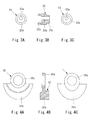
Fig. 3] Fig. 3A to Fig. 3C are views showing the bushing, whereinFig. 3A is a view of the bushing as viewed from one side in the axial direction,Fig. 3B is a cross-sectional side view of the bushing, andFig. 3C is a view of the bushing as viewed from the other side in the axial direction. - [
Fig. 4] Fig. 4A to Fig. 4C are views showing a balance weight, whereinFig. 4A is a view of the balance weight as viewed from one side in the axial direction,Fig. 4B is a cross-sectional side view of the balance weight, andFig. 4C is a view of the balance weight as viewed from the other side in the axial direction. - [
Fig. 5] Fig. 5A and Fig. 5B are enlarged views showing a state where the eccentric shaft which is provided to the end portion of the drive shaft is pivotally supported on the radial bearing which is mounted on the boss portion of the revolving scroll member by way of the bushing having one end portion on which a balance weight is mounted, whereinFig. 5A is a view showing a state where the drive shaft is not rotated, andFig. 5B is a view showing a state where the drive shaft is rotated so that the bushing is inclined. - [
Fig. 6] Fig. 6 is a cross-sectional view showing a conventional scroll-type compressor. - [
Fig. 7] Fig. 7 is a cross-sectional view showing another conventional scroll-type compressor. - [
Fig. 8] Fig. 8 is a cross-sectional view showing still another conventional scroll-type compressor. - [
Fig. 9] Fig. 9A and Fig. 9B are enlarged views showing a conventional state where an eccentric shaft which is provided to an end portion of a drive shaft is pivotally supported on a radial bearing which is mounted on a boss portion of a revolving scroll member by way of a bushing having one end on which a balance weight is mounted, whereinFig. 9A is a view showing a state where the drive shaft is not rotated, andFig. 9B is a view showing a state where the drive shaft is rotated and the bushing is inclined. - Hereinafter, a scroll-type compressor according to the present invention is explained in conjunction with drawings.
- In
Fig. 1 , a scroll-type compressor 1 is an electrically-operated compressor suitable for a refrigerating cycle which uses a refrigerant as a working fluid, wherein, in the inside of ahousing 2 which is made of an aluminum alloy, a compression mechanism 3 is arranged on a left side in the drawing, and an electrically-operatedmotor 4 for driving the compression mechanism 3 is arranged on a right side in the drawing. InFig. 1 , a front side of the compressor 1 is arranged on a right side in the drawing, and a rear side of the compressor is arranged on a left side in the drawing. - The
housing 2 includes: a compressionmechanism housing member 2a which houses the compression mechanism 3 therein, an electrically-operatedmotor housing member 2b which houses the electrically-operatedmotor 4 for driving the compression mechanism 3 therein; and aninverter housing member 2c which houses an inverter device not shown in the drawing for controlling driving of the electrically-operatedmotor 4 therein. These housing members are positioned by positioningpins 7 and are fastened to each other in the axial direction usingfastening bolts 8. - In the electrically-operated
motor housing member 2b, apartition wall 10 which is integrally formed with ashaft support portion 9a is provided on a side which faces the compressionmechanism housing member 2a. Also in theinverter housing member 2c, apartition wall 11 which is integrally formed with ashaft support portion 9b is provided on a side which faces the electrically-operatedmotor housing member 2b. Adrive shaft 12 is rotatably supported on theshaft support portions partition walls bearings partition walls motor housing member 2b and theinverter housing member 2c respectively, the inside of thehousing 2 is partitioned into: a compressionmechanism housing portion 15a which houses the compression mechanism 3 therein; an electrically-operatedmotor housing portion 15b which houses the electrically-operatedmotor 4 therein; and aninverter housing portion 15c which houses the inverter device therein in order from a rear side of thehousing 2. - In this embodiment, the
inverter housing portion 15c is defined by fixing alid body 16 to theinverter housing member 2c using bolts or the like not shown in the drawing. - The compression mechanism 3 is a scroll-type compression mechanism which includes a fixed
scroll member 21, and a revolvingscroll member 22 which is arranged so as to face the fixedscroll member 21 in an opposed manner. The fixedscroll member 21 is configured such that, while the movement of the fixedscroll member 21 in the axial direction with respect to thehousing 2 is allowed, the movement of the fixedscroll member 21 in the radial direction relative to thehousing 2 is restricted by apositioning pin 28. The fixedscroll member 21 is constituted of: a circular disc-shapedend plate 21a; a cylindrical outerperipheral wall 21b which is formed on and along an outer periphery of theend plate 21a over the whole circumference in an erected manner toward a front side; and aspiral wall 21c having a spiral shape which is formed on theend plate 21a in an erected manner inside the outerperipheral wall 21b such that thespiral wall 21c extends toward a front side. - The revolving
scroll member 22 is constituted of: a circular disc-shapedend plate 22a; and aspiral wall 22c having a spiral shape which is formed on theend plate 22a in an erected manner such that thespiral wall 22c extends toward a rear side. Aneccentric shaft 17 which is provided to a rear end portion of thedrive shaft 12 and is disposed eccentrically with respect to an axis of thedrive shaft 12 is supported on aboss portion 22b which is formed on a back surface of theend plate 22a in an erected manner by way of abushing 23 and aradial bearing 24 so that theeccentric shaft 17 is capable of performing the revolving motion about the axis of thedrive shaft 12. - The
spiral wall 21c of the fixedscroll member 21 and thespiral wall 22c of the revolvingscroll member 22 are meshed with each other so that acompression chamber 25 is defined in a space surrounded by theend plate 21a of the fixedscroll member 21, thespiral wall 21c of the fixedscroll member 21, theend plate 22a of the revolvingscroll member 22, and thespiral wall 22c of the revolvingscroll member 22. - An annular thrust race 26 having a thin plate shape is sandwiched between the outer
peripheral wall 21b of the fixedscroll member 21 and thepartition wall 10, and the fixedscroll member 21 and thepartition wall 10 are made to abut to each other by way of the thrust race 26. - The thrust race 26 is formed using a material having excellent wear resistance, and a center opening through which the
boss portion 22b of the revolvingscroll member 22 and anOldham ring 27 described later pass is formed in a center portion of the thrust race 26. Further, the respective positions of the fixedscroll member 21, the thrust race 26, and the electrically-operatedmotor housing member 2b in the radial direction are restricted by thepositioning pin 28 which is inserted into a pin insertion hole formed in the thrust race 26. - The
shaft support portion 9a which is integrally formed with thepartition wall 10 of the electrically-operatedmotor housing member 2b has a through hole at the center thereof, and a diameter of an inner surface of theshaft support portion 9a is increased toward the thrust race 26 in a stepwise manner. In theshaft support portion 9a, in order from a front side thereof remotest from the thrust race 26, a bearinghousing portion 31 in which thebearing 13 is housed, aweight housing portion 33 in which abalance weight 32 which is integrally formed with thebushing 23 or is fitted on the bushing in a non-rotatable manner relative to thebushing 23 and is rotatable along with the rotation of thedrive shaft 12 as an integral body with the busing 23 (in this embodiment, thebalance weight 32 being formed as a body separate from thebushing 23, and being fitted on thebushing 23 in a non-rotatable manner relative to the bushing 23) is housed, and an Oldham housing portion 34 which is formed continuously with theweight housing portion 33 and in which theOldham ring 27 which prevents the rotation between the revolvingscroll member 22 and the Oldham housing portion 34 is housed are formed. - Accordingly, although the revolving
scroll member 22 generates a rotational force due to the rotation of thedrive shaft 12, the revolvingscroll member 22 performs the revolving motion about the axis of thedrive shaft 12 while the rotation of the revolvingscroll member 22 is restricted by theOldham ring 27. - A
suction chamber 35 which sucks a refrigerant introduced from asuction port 40 described later through anintake passage 45 is formed between the outerperipheral wall 21b of the above-mentionedfixed scroll member 21 and an outermost peripheral portion of thespiral wall 22c of the revolvingscroll member 22. On a back side of the fixedscroll member 21 in the inside of the housing, adischarge chamber 37 into which a refrigerant gas which is compressed in thecompression chamber 25 is discharged through adischarge hole 36 which is formed on the approximately center of the fixedscroll member 21 is formed between a rear end wall of the compressionmechanism housing member 2a and the fixedscroll member 21. A refrigerant gas discharged into thedischarge chamber 37 is pressure-fed to an external refrigerant circuit through thedischarge port 38. - On the other hand, in an electrically-operated
motor housing portion 15b which is formed in the inside of thehousing 2 in front of thepartition wall 10, astator 41 and arotor 42 which constitute the electrically-operatedmotor 4 are arranged. Thestator 41 is constituted of a core 43 having a cylindrical shape and acoil 44 which is wound around thecore 43, and is fixed to an inner surface of the housing 2 (the electrically-operatedmotor housing member 2b). Therotor 42 made of magnet which is housed in the inside of thestator 41 in a rotatable manner is fixedly mounted on thedrive shaft 12. Therotor 42 is rotated by a rotational magnetic force generated by thestator 41 so that thedrive shaft 12 is rotated. The electrically-operatedmotor 4 which is formed of a brushless DC motor is constituted of thestator 41 and therotor 42. - The
suction port 40 through which a refrigerant gas is sucked into the electrically-operatedmotor housing portion 15b is formed in a side surface of the housing 2 (electrically-operatedmotor housing member 2b). Thesuction passage 45 which introduces a refrigerant flown into the electrically-operatedmotor housing portion 15b from thesuction port 40 into thesuction chamber 35 is formed through a gap formed between thestator 41 and the housing 2 (electrically-operatedmotor housing member 2b), a hole formed in thepartition wall 10, and a gap formed between thefixed scroll member 21 and thehousing 2. - The inverter device which is housed in the
inverter housing member 2c is electrically connected with thestator 41 via a terminal (airtight terminal) 60 which is mounted in a throughhole 61 formed in thepartition wall 11, and electricity is supplied to the electrically-operatedmotor 4 from the inverter device. - Accordingly, when the
rotor 42 is rotated with the supply of electricity to the electrically-operatedmotor 4 so that thedrive shaft 12 is rotated, in the compression mechanism 3, the revolvingscroll member 22 is rotated around an axis of theeccentric shaft 17 and hence, the revolvingscroll member 22 revolves around the axis of the fixedscroll member 21. Since the rotation of the revolvingscroll member 22 is prevented by the rotation prevention mechanism which is constituted of theOldham ring 27, only the revolving motion of the revolvingscroll member 22 is allowed. - Due to the revolving motion of the revolving
scroll member 22, thecompression chamber 25 is moved toward the center from outer peripheral sides of thespiral walls compression chamber 25 is gradually decreased and hence, a refrigerant gas sucked into thecompression chamber 25 from thesuction chamber 35 is compressed, and the compressed refrigerant gas is discharged into thedischarge chamber 37 through thedischarge hole 36 which is formed in theend plate 21a of the fixedscroll member 21. Then, the refrigerant gas is fed out to the external refrigerant circuit through thedischarge port 38. - In the above-mentioned constitution, as also shown in
Fig. 2 andFig. 3 , thebushing 23 has a columnar shape. Aneccentric hole 23a which extends in the axial direction and allows the insertion of theeccentric shaft 17 therein is formed in thebushing 23 at a position offset from the axis of thebushing 23 in the radial direction. A recessedportion 23b whose diameter is set larger than a diameter of theeccentric hole 23a is formed in a revolving scroll member -side end portion of thebushing 23. Aweight fitting margin 23c which has a small outer diameter and on which thebalance weight 32 is fitted is formed on the periphery of an electrically-operated-motor-side end portion of thebushing 23. - As also shown in
Fig. 4 , thebalance weight 32 is constituted of afitting portion 32a which is formed in an annular shape, and a fan-shapedweight body 32b which is integrally formed on the periphery of thefitting portion 32a over a predetermined angular range. Thefitting portion 32a is fitted on the outer periphery of the weightfitting margin 23c of thebushing 23 by press-fitting, for example, so that thebalance weight 32 is rotatable with thebushing 23. - The balance weight is formed such that the balance weight projects in the direction that the balance weight approaches the revolving scroll member and also in the direction away from the revolving scroll member. Due to such a constitution, it is possible to ensure a required mass while preventing the balance weight from interfering with the Oldham ring by decreasing a size of the balance weight in the radial direction.
- The
eccentric shaft 17 is a shaft having a circular columnar shape. Anannular groove 17a is formed on theeccentric shaft 17 at a position in the vicinity of one end of theeccentric shaft 17. An end portion of theeccentric shaft 17 on a side opposite to a side where theannular groove 17a is formed is press-fitted into and fixed to afitting hole 12a formed in an end surface of thedrive shaft 12 which faces the revolvingscroll member 22 in an opposed manner. An annular-groove-side end portion of theeccentric shaft 17 is inserted into theeccentric hole 23a of thebushing 23 in a relatively rotatable manner, and is projected into the recessedportion 23b. Asnap ring 29 is fitted in theannular groove 17a at the portion of theeccentric shaft 17 projected into the recessed portion 12b. Thebushing 23 is mounted on theeccentric shaft 17 in the above-mentioned manner. Accordingly, thebushing 23 is mounted on theeccentric shaft 17 in a relatively rotatable manner with respect to theeccentric shaft 17 while the movement of thebushing 23 in the axial direction is restricted. - The
radial bearing 24 which is fitted into theboss portion 22b of the revolvingscroll member 22 is constituted of a needle bearing where a large number of needle-shapedrollers 24a are arranged equidistantly in the circumferential direction, and thebushing 23 can be fitted into theradial bearing 24 in a relatively rotatable manner with a predetermined clearance between an outer peripheral surface of thebushing 23 and theradial bearing 24. - In this embodiment, the
radial bearing 24 is configured such that the number of rollers is set to 14, a length of a roller portion (a length of fitting between the roller and the outer peripheral surface of thebushing 23 in the axial direction) is set to 10mm, and a diameter of the roller is set to 2.5mm. Further, a length of fitting between the bushing and the eccentric shaft in the axial direction is set to 15mm, and a diameter of the eccentric shaft is set to 6mm. - According to the conventional general designing method, a clearance between a radial bearing and a member which is supported on the radial bearing (bushing in this embodiment) is usually set as small as possible by taking into account tolerance of the member such that the radial bearing and the member are brought into contact with each other in a state where they are arranged as parallel as possible. That is, although the
radial bearing 24 formed of the needle bearing is light-weighted and has a compact shape, theradial bearing 24 is not suitable for supporting an axial load or an inclination of the shaft. Accordingly, it is a common knowledge in designing that the inclination of the bushing is suppressed by controlling a clearance between the radial bearing and the member which is inserted into the radial bearing to a small value by matching-machining so that an offset load between the bushing and the needles is decreased. - However, the
balance weight 32 is mounted on a portion of one end portion of thebushing 23 projecting from theradial bearing 24 in the axial direction and hence, the axis of thebushing 23 tends to be inclined with respect to the axis of the eccentric shaft 17 (drive shaft 12) due to a centrifugal force of thebalance weight 32. Accordingly, to compensate for this inclination of thebushing 23 by making the clearance between the outer peripheral surface of thebushing 23 and theradial bearing 24 small, as described previously, thebushing 23 is brought into non-uniform contact with theradial bearing 24 at two different portions in the axial direction whereby an offset load is remarkably increased at a contact portion of an end portion side of thebushing 23 where thebalance weight 23 is mounted thus giving rise to a drawback that flaking occurs at the contact portion. - According to the present invention, to decrease a local load (offset load) on the end portion side of the bushing where the balance weight is mounted, as shown in
Fig. 5A , a clearance A between the outer peripheral surface of theeccentric shaft 17 which is inserted into theeccentric hole 23a and the inner peripheral surface of theeccentric hole 23a is set smaller than a clearance C between the outer peripheral surface of thebushing 23 and the inner peripheral surface of theradial bearing 24. - To be more specific, assuming the clearance between the outer peripheral surface of the
eccentric shaft 17 and the inner peripheral surface of theeccentric hole 23a formed in thebushing 23 as A, a length of fitting between the outer peripheral surface of theeccentric shaft 17 and the inner peripheral surface of theeccentric hole 23a as B, a clearance between the outer peripheral surface of thebushing 23 and the inner peripheral surface of theradial bearing 24 as C, and a length of fitting between the outer peripheral surface of thebushing 23 and the inner peripheral surface of theradial bearing 24 as D, A is set to 6 to 22µm, C is set to 24 to 48µm, and these values are also set so as to satisfy the relationship of A/B < C/D. - In such a constitution, the center of gravity of the
balance weight 32 which is mounted on the end portion of thebushing 23 projecting from theradial bearing 24 is displaced from the center of the eccentric shaft 17 (a centrifugal force of the balance weight acts on the end portion of thebushing 23 projecting from the radial bearing 24). Accordingly, as shown inFig. 5B , the axis of thebushing 23 is inclined with respect to the axis of theeccentric shaft 17. In such a state, the outer peripheral surface of thebushing 23 is brought into non-uniform contact with theradial bearing 24, a centrifugal force of thebalance weight 32 acts on the revolvingscroll member 22 by way of thebushing 23 and theradial bearing 24 so that the centrifugal force of thebalance weight 32 and a centrifugal force of the revolvingscroll member 22 cancel each other. In this case, the clearance A between the outer peripheral surface of theeccentric shaft 17 which is inserted into theeccentric hole 23a and the inner peripheral surface of theeccentric hole 23a is set smaller than the clearance C between the outer peripheral surface of thebushing 23 and the inner peripheral surface of theradial bearing 24 and hence, the inclination of thebushing 23 is restricted by the eccentric shaft 17 (thebushing 23 being mainly supported on the eccentric shaft 17), and thebushing 23 is brought into contact with theradial bearing 24 only at one portion (the outer peripheral surface of thebushing 23 being brought into contact with only the end portion side of theradial bearing 24 on which thebalance weight 32 is mounted but not being brought into contact with the end portion side of the radial bearing remote from the balance weight 32). Accordingly, the previously-mentioned load F3 (shown inFig. 9 ) is not generated and hence, there exists no possibility that a load F2 which acts on a portion of the end portion side of thebushing 23 which is brought into contact with theradial bearing 24 on which thebalance weight 32 is mounted is remarkably increased whereby the load F2 becomes substantially equal to a load F1. - As a matter of course, in an actual operation, due to a compressive reaction force generated along with the compression of a refrigerant gas in the inside of the
compression chamber 25 defined between the revolvingscroll member 22 and the fixedscroll member 21, a force which acts in the direction from a viewer's side to a depth side with respect to a paper plane on which the drawing is described is applied and hence, thebushing 23 and theradial bearing 24 are brought into contact with each other at a point where a resultant of these forces acts on. Accordingly, in the conventional configuration, forces F3 and F2 which act in the directions opposite to each other are generated at two portions at a front side and a rear side of thebushing 23 respectively and hence, a contact portion of thebushing 23 is twisted three-dimensionally. However, according to the present invention, a load F3 does not act on thebushing 23 and hence, such a twisted contact can be suppressed. - Further, in the above-mentioned constitution, the inclination of the
bushing 23 is supported by the outer peripheral surface of theeccentric shaft 17 and the fitting portion of theeccentric hole 23a which is formed in thebushing 23 and hence, local loads (α1, α2) are generated at contact portions between theeccentric shaft 17 and theeccentric hole 23a. However, thebushing 23 is not rotatable relative to theeccentric shaft 17 and hence, sliding and rolling are not generated at the contact portion whereby there exists no possibility that flaking or wear is generated. - As described previously, in the general designing method, the clearance C is controlled by applying forming (so-called matching forming) to the outer peripheral surface of the
bushing 23 in conformity with a size of the inner peripheral surface of theradial bearing 24. In the above-mentioned constitution, however, it is no more necessary to control the clearance C such that the clearance C becomes small and hence, matching forming can be omitted. The clearance A may be set to 6 to 12µm by applying matching forming to the control of clearance A (by forming the outer peripheral surface of theeccentric shaft 17 in accordance with a size of the inner peripheral surface of theeccentric hole 23a). Due to such a constitution, the inclination of the bushing which is supported with the clearance A can be further decreased without increasing man-hours for forming compared to the conventional technique. - Accordingly, an offset load which acts on the radial bearing 24 (
roller 24a) can be decreased. Even when thebushing 23 is brought into local contact with theroller 24a of theradial bearing 24 due to a non-uniform contact, the generation of flaking can be suppressed and hence, a yield strength of theradial bearing 24 can be relatively enhanced (resulting in that large-sizing of theradial bearing 24 for ensuring a yield strength of theradial bearing 24 becomes unnecessary). - In the above-mentioned constitution, the
balance weight 32 is formed such that thebalance weight 32 projects also in the direction away from the revolvingscroll member 22 and hence, a length of the balance weight in the radial direction can be suppressed and, further, thebalance weight 32 can be mounted such that thebalance weight 32 does not interfere with the rotation prevention mechanism (Oldham ring 27). Accordingly, the increase in diameter of theOldham ring 27 can be prevented so that an outer diameter of the revolving scroll member can be made small. - In the above-mentioned constitution, the needle bearing is used as the
radial bearing 24 and hence, a weight of the bearing per se can be decreased. Further, a size of the radial bearing in the radial direction can be also made compact and hence, the balance weight can be made light-weighted. -
- 1: scroll-type compressor
- 2: housing
- 21: fixed scroll member
- 21a: end plate
- 21c: spiral wall
- 22: revolving scroll member
- 22a: end plate
- 22b: boss portion
- 22c: spiral wall
- 23: bushing
- 23a: eccentric hole
- 24: radial bearing
- 32: balance weight
Claims (4)
- Scroll-type compressor comprising:a fixed scroll member whose movement in the radial direction with respect to a housing is restricted, the fixed scroll member having an end plate and a spiral wall which is formed on the end plate in an erected manner;a revolving scroll member which is arranged so as to face the fixed scroll member in an opposed manner, the revolving scroll member having an end plate and a spiral wall which is formed on the end plate in an erected manner;a drive shaft which transmits rotational power;an eccentric shaft which is provided to an end portion of the drive shaft at a position offset from an axis of the drive shaft;a radial bearing which is fitted into a boss portion formed on a back surface of the revolving scroll member;a bushing which has an eccentric hole into which the eccentric shaft is inserted, the bushing being fitted on the eccentric shaft by way of the eccentric hole, and the bushing being relatively rotatably supported on the radial bearing; anda balance weight which is mounted on one end portion of the bushing and forms an integral body with the bushing, characterized in thatthe bushing is configured such that, when the bushing is inclined, an outer peripheral surface of the bushing is brought into contact with the radial bearing only on an end portion side on which the balance weight is mounted.
- Scroll-type compressor according to claim 1, wherein assuming a clearance between the eccentric shaft and an inner peripheral surface of the eccentric hole formed in the bushing as A, a length of fitting between the eccentric shaft and the inner peripheral surface of the eccentric hole formed in the bushing as B, a clearance between the radial bearing and an outer peripheral surface of the bushing as C, and a length of fitting between the radial bearing and the outer peripheral surface of the bushing as D, the relationship A/B < C/D is established.
- Scroll-type compressor according to claim 1 or claim 2, wherein a rotation prevention mechanism is arranged outside the boss portion of the revolving scroll member in the radial direction, and the interference of the balance weight with the rotation prevention mechanism is prevented by forming the balance weight in such a manner that the balance weight proj ects in the direction away from the revolving scroll member.
- Scroll-type compressor according to any one of claims 1 to 3, wherein the radial bearing is a needle bearing.Claim 4]
Applications Claiming Priority (2)
| Application Number | Priority Date | Filing Date | Title |
|---|---|---|---|
| JP2011096236A JP5594846B2 (en) | 2011-04-22 | 2011-04-22 | Scroll compressor |
| PCT/JP2012/002731 WO2012144224A1 (en) | 2011-04-22 | 2012-04-20 | Scroll compressor |
Publications (3)
| Publication Number | Publication Date |
|---|---|
| EP2713053A1 true EP2713053A1 (en) | 2014-04-02 |
| EP2713053A4 EP2713053A4 (en) | 2014-11-26 |
| EP2713053B1 EP2713053B1 (en) | 2016-04-13 |
Family
ID=47041354
Family Applications (1)
| Application Number | Title | Priority Date | Filing Date |
|---|---|---|---|
| EP12773817.7A Not-in-force EP2713053B1 (en) | 2011-04-22 | 2012-04-20 | Scroll compressor |
Country Status (4)
| Country | Link |
|---|---|
| EP (1) | EP2713053B1 (en) |
| JP (1) | JP5594846B2 (en) |
| CN (1) | CN103477079B (en) |
| WO (1) | WO2012144224A1 (en) |
Cited By (7)
| Publication number | Priority date | Publication date | Assignee | Title |
|---|---|---|---|---|
| EP2913531A1 (en) * | 2014-02-28 | 2015-09-02 | Mitsubishi Heavy Industries, Ltd. | Scroll compressor with balance weight |
| US9670927B2 (en) | 2013-03-06 | 2017-06-06 | Kabushiki Kaisha Toyota Jidoshokki | Scroll compressor with a balancer and elastic member |
| DE102020211559A1 (en) | 2020-09-15 | 2022-03-17 | Brose Fahrzeugteile SE & Co. Kommanditgesellschaft, Würzburg | scroll compressor |
| US20220213894A1 (en) * | 2019-04-26 | 2022-07-07 | Edwards Limited | Scroll pump crank sleeve |
| US11655819B2 (en) | 2018-08-13 | 2023-05-23 | Mitsubishi Heavy Industries Thermal Systems, Ltd. | Scroll compressor |
| US11867182B2 (en) | 2020-01-21 | 2024-01-09 | Copeland Climate Technologies (Suzhou) Co. Ltd. | Scroll compressor |
| US20250052239A1 (en) * | 2023-08-11 | 2025-02-13 | Fu Sheng Industrial Co. Ltd. | Compressor |
Families Citing this family (10)
| Publication number | Priority date | Publication date | Assignee | Title |
|---|---|---|---|---|
| JP6208534B2 (en) * | 2013-10-25 | 2017-10-04 | 株式会社ヴァレオジャパン | Electric scroll compressor |
| CN104047851A (en) * | 2014-07-11 | 2014-09-17 | 湖南联力精密机械有限公司 | Vortex air compressor with radially sealable movable and static discs |
| WO2016038694A1 (en) * | 2014-09-10 | 2016-03-17 | 株式会社日立産機システム | Scroll fluid machine |
| KR102291952B1 (en) * | 2015-03-04 | 2021-08-23 | 한온시스템 주식회사 | A eccentric bush assembling structure of a scroll compressor |
| JP2019100246A (en) * | 2017-11-30 | 2019-06-24 | サンデン・オートモーティブコンポーネント株式会社 | Scroll type fluid machine |
| JP7056821B2 (en) * | 2018-08-31 | 2022-04-19 | サンデン・オートモーティブコンポーネント株式会社 | Scroll compressor |
| KR102097499B1 (en) * | 2018-09-17 | 2020-04-06 | 엘지전자 주식회사 | Scroll compressor |
| CN111089055B (en) * | 2018-10-23 | 2024-09-06 | 谷轮环境科技(苏州)有限公司 | Scroll compressor having a rotor with a rotor shaft having a rotor shaft with a |
| KR102503234B1 (en) * | 2018-11-30 | 2023-02-24 | 한온시스템 주식회사 | Scroll compressor |
| CN113530814B (en) * | 2020-04-17 | 2025-08-08 | 谷轮环境科技(苏州)有限公司 | scroll compressor |
Family Cites Families (12)
| Publication number | Priority date | Publication date | Assignee | Title |
|---|---|---|---|---|
| JP3017641B2 (en) | 1994-07-27 | 2000-03-13 | 株式会社豊田自動織機製作所 | Scroll compressor |
| JP2734408B2 (en) | 1995-06-23 | 1998-03-30 | 三菱電機株式会社 | Scroll compressor |
| JP3214417B2 (en) * | 1997-11-11 | 2001-10-02 | ダイキン工業株式会社 | Scroll type fluid machine |
| US6015277A (en) * | 1997-11-13 | 2000-01-18 | Tecumseh Products Company | Fabrication method for semiconductor substrate |
| EP0921316A1 (en) * | 1997-12-03 | 1999-06-09 | Sanden Corporation | Scroll compressor with radial guiding pin in eccentric bush |
| JP4958329B2 (en) * | 1997-12-03 | 2012-06-20 | サンデン株式会社 | Scroll compressor |
| JP2001093554A (en) * | 1999-09-28 | 2001-04-06 | Toyota Autom Loom Works Ltd | Compressor and regenerator for fuel cell |
| JP4597358B2 (en) * | 2000-12-22 | 2010-12-15 | 株式会社日本自動車部品総合研究所 | Scroll compressor |
| GB0426937D0 (en) * | 2004-12-08 | 2005-01-12 | Boc Group Plc | Scroll-type apparatus |
| CN2821227Y (en) * | 2005-07-14 | 2006-09-27 | 乐金电子(天津)电器有限公司 | Vortex compressor with movable balance hammer |
| JP5075810B2 (en) * | 2008-12-26 | 2012-11-21 | 株式会社日立産機システム | Scroll type fluid machine |
| JP2010196630A (en) | 2009-02-26 | 2010-09-09 | Denso Corp | Compressor |
-
2011
- 2011-04-22 JP JP2011096236A patent/JP5594846B2/en not_active Expired - Fee Related
-
2012
- 2012-04-20 WO PCT/JP2012/002731 patent/WO2012144224A1/en not_active Ceased
- 2012-04-20 EP EP12773817.7A patent/EP2713053B1/en not_active Not-in-force
- 2012-04-20 CN CN201280018752.XA patent/CN103477079B/en not_active Expired - Fee Related
Cited By (8)
| Publication number | Priority date | Publication date | Assignee | Title |
|---|---|---|---|---|
| US9670927B2 (en) | 2013-03-06 | 2017-06-06 | Kabushiki Kaisha Toyota Jidoshokki | Scroll compressor with a balancer and elastic member |
| EP2913531A1 (en) * | 2014-02-28 | 2015-09-02 | Mitsubishi Heavy Industries, Ltd. | Scroll compressor with balance weight |
| US11655819B2 (en) | 2018-08-13 | 2023-05-23 | Mitsubishi Heavy Industries Thermal Systems, Ltd. | Scroll compressor |
| US20220213894A1 (en) * | 2019-04-26 | 2022-07-07 | Edwards Limited | Scroll pump crank sleeve |
| US11867182B2 (en) | 2020-01-21 | 2024-01-09 | Copeland Climate Technologies (Suzhou) Co. Ltd. | Scroll compressor |
| DE102020211559A1 (en) | 2020-09-15 | 2022-03-17 | Brose Fahrzeugteile SE & Co. Kommanditgesellschaft, Würzburg | scroll compressor |
| US20250052239A1 (en) * | 2023-08-11 | 2025-02-13 | Fu Sheng Industrial Co. Ltd. | Compressor |
| US12320352B2 (en) * | 2023-08-11 | 2025-06-03 | Fu Sheng Industrial Co. Ltd. | Compressor |
Also Published As
| Publication number | Publication date |
|---|---|
| CN103477079A (en) | 2013-12-25 |
| JP2012225328A (en) | 2012-11-15 |
| WO2012144224A1 (en) | 2012-10-26 |
| JP5594846B2 (en) | 2014-09-24 |
| EP2713053B1 (en) | 2016-04-13 |
| EP2713053A4 (en) | 2014-11-26 |
| CN103477079B (en) | 2016-01-20 |
Similar Documents
| Publication | Publication Date | Title |
|---|---|---|
| EP2713053B1 (en) | Scroll compressor | |
| KR102292995B1 (en) | Scroll compressor | |
| EP3239526B1 (en) | Electrically driven scroll compressor | |
| CN112443484B (en) | Electric compressor | |
| JP2020105933A (en) | Electric compressor | |
| WO2017057159A1 (en) | Scroll-type compressor | |
| US11473580B2 (en) | Electric compressor | |
| WO2021010099A1 (en) | Scroll compressor | |
| US12012959B2 (en) | Scroll compressor | |
| WO2007123016A1 (en) | Scroll-type fluid machine | |
| JP7188200B2 (en) | scroll compressor | |
| US20260022699A1 (en) | Scroll compressor with shaft balancer and bushing balancer | |
| US9400016B2 (en) | Radial roller bearing, rotary machine including radial roller bearing, and method for designing radial roller bearing | |
| EP3388673A1 (en) | Scroll compressor | |
| KR102097499B1 (en) | Scroll compressor | |
| JP7819603B2 (en) | Scroll Compressor | |
| JP2017078360A (en) | Scroll fluid machinery | |
| EP2383481B1 (en) | Rotational machine | |
| JP7614982B2 (en) | Scroll Compressor | |
| US10253773B2 (en) | Attachment structure for compressor | |
| KR101682250B1 (en) | Electronic Compressor | |
| CN121285694A (en) | Motorized device comprising a component with eccentric movement | |
| WO2026083649A1 (en) | Scroll compressor | |
| KR20200140428A (en) | Scroll type compressor | |
| JPH09105389A (en) | Scroll compressor |
Legal Events
| Date | Code | Title | Description |
|---|---|---|---|
| PUAI | Public reference made under article 153(3) epc to a published international application that has entered the european phase |
Free format text: ORIGINAL CODE: 0009012 |
|
| 17P | Request for examination filed |
Effective date: 20131122 |
|
| AK | Designated contracting states |
Kind code of ref document: A1 Designated state(s): AL AT BE BG CH CY CZ DE DK EE ES FI FR GB GR HR HU IE IS IT LI LT LU LV MC MK MT NL NO PL PT RO RS SE SI SK SM TR |
|
| DAX | Request for extension of the european patent (deleted) | ||
| A4 | Supplementary search report drawn up and despatched |
Effective date: 20141027 |
|
| RIC1 | Information provided on ipc code assigned before grant |
Ipc: F04C 18/02 20060101AFI20141021BHEP Ipc: F04C 29/00 20060101ALI20141021BHEP Ipc: F01C 21/02 20060101ALI20141021BHEP |
|
| GRAP | Despatch of communication of intention to grant a patent |
Free format text: ORIGINAL CODE: EPIDOSNIGR1 |
|
| RIC1 | Information provided on ipc code assigned before grant |
Ipc: F01C 21/02 20060101ALI20150611BHEP Ipc: F04C 18/02 20060101AFI20150611BHEP Ipc: F04C 29/00 20060101ALI20150611BHEP |
|
| INTG | Intention to grant announced |
Effective date: 20150716 |
|
| GRAS | Grant fee paid |
Free format text: ORIGINAL CODE: EPIDOSNIGR3 |
|
| GRAA | (expected) grant |
Free format text: ORIGINAL CODE: 0009210 |
|
| AK | Designated contracting states |
Kind code of ref document: B1 Designated state(s): AL AT BE BG CH CY CZ DE DK EE ES FI FR GB GR HR HU IE IS IT LI LT LU LV MC MK MT NL NO PL PT RO RS SE SI SK SM TR |
|
| REG | Reference to a national code |
Ref country code: GB Ref legal event code: FG4D |
|
| REG | Reference to a national code |
Ref country code: AT Ref legal event code: REF Ref document number: 790468 Country of ref document: AT Kind code of ref document: T Effective date: 20160415 Ref country code: CH Ref legal event code: EP |
|
| REG | Reference to a national code |
Ref country code: IE Ref legal event code: FG4D |
|
| REG | Reference to a national code |
Ref country code: DE Ref legal event code: R096 Ref document number: 602012017095 Country of ref document: DE |
|
| REG | Reference to a national code |
Ref country code: LT Ref legal event code: MG4D |
|
| PG25 | Lapsed in a contracting state [announced via postgrant information from national office to epo] |
Ref country code: BE Free format text: LAPSE BECAUSE OF NON-PAYMENT OF DUE FEES Effective date: 20160430 |
|
| REG | Reference to a national code |
Ref country code: AT Ref legal event code: MK05 Ref document number: 790468 Country of ref document: AT Kind code of ref document: T Effective date: 20160413 |
|
| REG | Reference to a national code |
Ref country code: NL Ref legal event code: MP Effective date: 20160413 |
|
| PG25 | Lapsed in a contracting state [announced via postgrant information from national office to epo] |
Ref country code: NO Free format text: LAPSE BECAUSE OF FAILURE TO SUBMIT A TRANSLATION OF THE DESCRIPTION OR TO PAY THE FEE WITHIN THE PRESCRIBED TIME-LIMIT Effective date: 20160713 Ref country code: NL Free format text: LAPSE BECAUSE OF FAILURE TO SUBMIT A TRANSLATION OF THE DESCRIPTION OR TO PAY THE FEE WITHIN THE PRESCRIBED TIME-LIMIT Effective date: 20160413 Ref country code: LT Free format text: LAPSE BECAUSE OF FAILURE TO SUBMIT A TRANSLATION OF THE DESCRIPTION OR TO PAY THE FEE WITHIN THE PRESCRIBED TIME-LIMIT Effective date: 20160413 Ref country code: PL Free format text: LAPSE BECAUSE OF FAILURE TO SUBMIT A TRANSLATION OF THE DESCRIPTION OR TO PAY THE FEE WITHIN THE PRESCRIBED TIME-LIMIT Effective date: 20160413 Ref country code: FI Free format text: LAPSE BECAUSE OF FAILURE TO SUBMIT A TRANSLATION OF THE DESCRIPTION OR TO PAY THE FEE WITHIN THE PRESCRIBED TIME-LIMIT Effective date: 20160413 |
|
| REG | Reference to a national code |
Ref country code: DE Ref legal event code: R119 Ref document number: 602012017095 Country of ref document: DE |
|
| PG25 | Lapsed in a contracting state [announced via postgrant information from national office to epo] |
Ref country code: ES Free format text: LAPSE BECAUSE OF FAILURE TO SUBMIT A TRANSLATION OF THE DESCRIPTION OR TO PAY THE FEE WITHIN THE PRESCRIBED TIME-LIMIT Effective date: 20160413 Ref country code: PT Free format text: LAPSE BECAUSE OF FAILURE TO SUBMIT A TRANSLATION OF THE DESCRIPTION OR TO PAY THE FEE WITHIN THE PRESCRIBED TIME-LIMIT Effective date: 20160816 Ref country code: HR Free format text: LAPSE BECAUSE OF FAILURE TO SUBMIT A TRANSLATION OF THE DESCRIPTION OR TO PAY THE FEE WITHIN THE PRESCRIBED TIME-LIMIT Effective date: 20160413 Ref country code: AT Free format text: LAPSE BECAUSE OF FAILURE TO SUBMIT A TRANSLATION OF THE DESCRIPTION OR TO PAY THE FEE WITHIN THE PRESCRIBED TIME-LIMIT Effective date: 20160413 Ref country code: SE Free format text: LAPSE BECAUSE OF FAILURE TO SUBMIT A TRANSLATION OF THE DESCRIPTION OR TO PAY THE FEE WITHIN THE PRESCRIBED TIME-LIMIT Effective date: 20160413 Ref country code: GR Free format text: LAPSE BECAUSE OF FAILURE TO SUBMIT A TRANSLATION OF THE DESCRIPTION OR TO PAY THE FEE WITHIN THE PRESCRIBED TIME-LIMIT Effective date: 20160714 Ref country code: LV Free format text: LAPSE BECAUSE OF FAILURE TO SUBMIT A TRANSLATION OF THE DESCRIPTION OR TO PAY THE FEE WITHIN THE PRESCRIBED TIME-LIMIT Effective date: 20160413 Ref country code: RS Free format text: LAPSE BECAUSE OF FAILURE TO SUBMIT A TRANSLATION OF THE DESCRIPTION OR TO PAY THE FEE WITHIN THE PRESCRIBED TIME-LIMIT Effective date: 20160413 |
|
| REG | Reference to a national code |
Ref country code: CH Ref legal event code: PL |
|
| PG25 | Lapsed in a contracting state [announced via postgrant information from national office to epo] |
Ref country code: BE Free format text: LAPSE BECAUSE OF FAILURE TO SUBMIT A TRANSLATION OF THE DESCRIPTION OR TO PAY THE FEE WITHIN THE PRESCRIBED TIME-LIMIT Effective date: 20160413 Ref country code: IT Free format text: LAPSE BECAUSE OF FAILURE TO SUBMIT A TRANSLATION OF THE DESCRIPTION OR TO PAY THE FEE WITHIN THE PRESCRIBED TIME-LIMIT Effective date: 20160413 |
|
| REG | Reference to a national code |
Ref country code: IE Ref legal event code: MM4A |
|
| PG25 | Lapsed in a contracting state [announced via postgrant information from national office to epo] |
Ref country code: CZ Free format text: LAPSE BECAUSE OF FAILURE TO SUBMIT A TRANSLATION OF THE DESCRIPTION OR TO PAY THE FEE WITHIN THE PRESCRIBED TIME-LIMIT Effective date: 20160413 Ref country code: DK Free format text: LAPSE BECAUSE OF FAILURE TO SUBMIT A TRANSLATION OF THE DESCRIPTION OR TO PAY THE FEE WITHIN THE PRESCRIBED TIME-LIMIT Effective date: 20160413 Ref country code: RO Free format text: LAPSE BECAUSE OF FAILURE TO SUBMIT A TRANSLATION OF THE DESCRIPTION OR TO PAY THE FEE WITHIN THE PRESCRIBED TIME-LIMIT Effective date: 20160413 Ref country code: SK Free format text: LAPSE BECAUSE OF FAILURE TO SUBMIT A TRANSLATION OF THE DESCRIPTION OR TO PAY THE FEE WITHIN THE PRESCRIBED TIME-LIMIT Effective date: 20160413 Ref country code: CH Free format text: LAPSE BECAUSE OF NON-PAYMENT OF DUE FEES Effective date: 20160430 Ref country code: DE Free format text: LAPSE BECAUSE OF NON-PAYMENT OF DUE FEES Effective date: 20161101 Ref country code: EE Free format text: LAPSE BECAUSE OF FAILURE TO SUBMIT A TRANSLATION OF THE DESCRIPTION OR TO PAY THE FEE WITHIN THE PRESCRIBED TIME-LIMIT Effective date: 20160413 Ref country code: LI Free format text: LAPSE BECAUSE OF NON-PAYMENT OF DUE FEES Effective date: 20160430 Ref country code: MC Free format text: LAPSE BECAUSE OF FAILURE TO SUBMIT A TRANSLATION OF THE DESCRIPTION OR TO PAY THE FEE WITHIN THE PRESCRIBED TIME-LIMIT Effective date: 20160413 |
|
| PLBE | No opposition filed within time limit |
Free format text: ORIGINAL CODE: 0009261 |
|
| STAA | Information on the status of an ep patent application or granted ep patent |
Free format text: STATUS: NO OPPOSITION FILED WITHIN TIME LIMIT |
|
| PG25 | Lapsed in a contracting state [announced via postgrant information from national office to epo] |
Ref country code: SM Free format text: LAPSE BECAUSE OF FAILURE TO SUBMIT A TRANSLATION OF THE DESCRIPTION OR TO PAY THE FEE WITHIN THE PRESCRIBED TIME-LIMIT Effective date: 20160413 |
|
| REG | Reference to a national code |
Ref country code: FR Ref legal event code: ST Effective date: 20170213 |
|
| 26N | No opposition filed |
Effective date: 20170116 |
|
| GBPC | Gb: european patent ceased through non-payment of renewal fee |
Effective date: 20160713 |
|
| PG25 | Lapsed in a contracting state [announced via postgrant information from national office to epo] |
Ref country code: FR Free format text: LAPSE BECAUSE OF NON-PAYMENT OF DUE FEES Effective date: 20160613 |
|
| PG25 | Lapsed in a contracting state [announced via postgrant information from national office to epo] |
Ref country code: GB Free format text: LAPSE BECAUSE OF NON-PAYMENT OF DUE FEES Effective date: 20160713 Ref country code: IE Free format text: LAPSE BECAUSE OF NON-PAYMENT OF DUE FEES Effective date: 20160420 Ref country code: SI Free format text: LAPSE BECAUSE OF FAILURE TO SUBMIT A TRANSLATION OF THE DESCRIPTION OR TO PAY THE FEE WITHIN THE PRESCRIBED TIME-LIMIT Effective date: 20160413 |
|
| PG25 | Lapsed in a contracting state [announced via postgrant information from national office to epo] |
Ref country code: CY Free format text: LAPSE BECAUSE OF FAILURE TO SUBMIT A TRANSLATION OF THE DESCRIPTION OR TO PAY THE FEE WITHIN THE PRESCRIBED TIME-LIMIT Effective date: 20160413 Ref country code: HU Free format text: LAPSE BECAUSE OF FAILURE TO SUBMIT A TRANSLATION OF THE DESCRIPTION OR TO PAY THE FEE WITHIN THE PRESCRIBED TIME-LIMIT; INVALID AB INITIO Effective date: 20120420 |
|
| PG25 | Lapsed in a contracting state [announced via postgrant information from national office to epo] |
Ref country code: LU Free format text: LAPSE BECAUSE OF NON-PAYMENT OF DUE FEES Effective date: 20160420 Ref country code: MK Free format text: LAPSE BECAUSE OF FAILURE TO SUBMIT A TRANSLATION OF THE DESCRIPTION OR TO PAY THE FEE WITHIN THE PRESCRIBED TIME-LIMIT Effective date: 20160413 Ref country code: TR Free format text: LAPSE BECAUSE OF FAILURE TO SUBMIT A TRANSLATION OF THE DESCRIPTION OR TO PAY THE FEE WITHIN THE PRESCRIBED TIME-LIMIT Effective date: 20160413 Ref country code: MT Free format text: LAPSE BECAUSE OF NON-PAYMENT OF DUE FEES Effective date: 20160430 Ref country code: IS Free format text: LAPSE BECAUSE OF FAILURE TO SUBMIT A TRANSLATION OF THE DESCRIPTION OR TO PAY THE FEE WITHIN THE PRESCRIBED TIME-LIMIT Effective date: 20160413 |
|
| PG25 | Lapsed in a contracting state [announced via postgrant information from national office to epo] |
Ref country code: BG Free format text: LAPSE BECAUSE OF FAILURE TO SUBMIT A TRANSLATION OF THE DESCRIPTION OR TO PAY THE FEE WITHIN THE PRESCRIBED TIME-LIMIT Effective date: 20160413 |
|
| PG25 | Lapsed in a contracting state [announced via postgrant information from national office to epo] |
Ref country code: AL Free format text: LAPSE BECAUSE OF FAILURE TO SUBMIT A TRANSLATION OF THE DESCRIPTION OR TO PAY THE FEE WITHIN THE PRESCRIBED TIME-LIMIT Effective date: 20160413 |
|
| P01 | Opt-out of the competence of the unified patent court (upc) registered |
Effective date: 20230629 |