EP2712992B1 - Movement device and assembly - Google Patents
Movement device and assembly Download PDFInfo
- Publication number
- EP2712992B1 EP2712992B1 EP13199714.0A EP13199714A EP2712992B1 EP 2712992 B1 EP2712992 B1 EP 2712992B1 EP 13199714 A EP13199714 A EP 13199714A EP 2712992 B1 EP2712992 B1 EP 2712992B1
- Authority
- EP
- European Patent Office
- Prior art keywords
- translation
- mobile element
- along
- axis
- deviator
- Prior art date
- Legal status (The legal status is an assumption and is not a legal conclusion. Google has not performed a legal analysis and makes no representation as to the accuracy of the status listed.)
- Active
Links
Images




Classifications
-
- E—FIXED CONSTRUCTIONS
- E05—LOCKS; KEYS; WINDOW OR DOOR FITTINGS; SAFES
- E05F—DEVICES FOR MOVING WINGS INTO OPEN OR CLOSED POSITION; CHECKS FOR WINGS; WING FITTINGS NOT OTHERWISE PROVIDED FOR, CONCERNED WITH THE FUNCTIONING OF THE WING
- E05F15/00—Power-operated mechanisms for wings
- E05F15/60—Power-operated mechanisms for wings using electrical actuators
- E05F15/603—Power-operated mechanisms for wings using electrical actuators using rotary electromotors
- E05F15/632—Power-operated mechanisms for wings using electrical actuators using rotary electromotors for horizontally-sliding wings
-
- E—FIXED CONSTRUCTIONS
- E05—LOCKS; KEYS; WINDOW OR DOOR FITTINGS; SAFES
- E05D—HINGES OR SUSPENSION DEVICES FOR DOORS, WINDOWS OR WINGS
- E05D15/00—Suspension arrangements for wings
- E05D15/06—Suspension arrangements for wings for wings sliding horizontally more or less in their own plane
- E05D15/10—Suspension arrangements for wings for wings sliding horizontally more or less in their own plane movable out of one plane into a second parallel plane
- E05D15/1042—Suspension arrangements for wings for wings sliding horizontally more or less in their own plane movable out of one plane into a second parallel plane with transversely moving carriage
- E05D15/1047—Suspension arrangements for wings for wings sliding horizontally more or less in their own plane movable out of one plane into a second parallel plane with transversely moving carriage specially adapted for vehicles
-
- E—FIXED CONSTRUCTIONS
- E05—LOCKS; KEYS; WINDOW OR DOOR FITTINGS; SAFES
- E05D—HINGES OR SUSPENSION DEVICES FOR DOORS, WINDOWS OR WINGS
- E05D15/00—Suspension arrangements for wings
- E05D15/06—Suspension arrangements for wings for wings sliding horizontally more or less in their own plane
- E05D15/10—Suspension arrangements for wings for wings sliding horizontally more or less in their own plane movable out of one plane into a second parallel plane
- E05D15/1042—Suspension arrangements for wings for wings sliding horizontally more or less in their own plane movable out of one plane into a second parallel plane with transversely moving carriage
- E05D2015/106—Suspension arrangements for wings for wings sliding horizontally more or less in their own plane movable out of one plane into a second parallel plane with transversely moving carriage transversely orientated track sections
-
- E—FIXED CONSTRUCTIONS
- E05—LOCKS; KEYS; WINDOW OR DOOR FITTINGS; SAFES
- E05Y—INDEXING SCHEME ASSOCIATED WITH SUBCLASSES E05D AND E05F, RELATING TO CONSTRUCTION ELEMENTS, ELECTRIC CONTROL, POWER SUPPLY, POWER SIGNAL OR TRANSMISSION, USER INTERFACES, MOUNTING OR COUPLING, DETAILS, ACCESSORIES, AUXILIARY OPERATIONS NOT OTHERWISE PROVIDED FOR, APPLICATION THEREOF
- E05Y2201/00—Constructional elements; Accessories therefor
- E05Y2201/60—Suspension or transmission members; Accessories therefor
- E05Y2201/622—Suspension or transmission members elements
- E05Y2201/676—Transmission of human force
-
- E—FIXED CONSTRUCTIONS
- E05—LOCKS; KEYS; WINDOW OR DOOR FITTINGS; SAFES
- E05Y—INDEXING SCHEME ASSOCIATED WITH SUBCLASSES E05D AND E05F, RELATING TO CONSTRUCTION ELEMENTS, ELECTRIC CONTROL, POWER SUPPLY, POWER SIGNAL OR TRANSMISSION, USER INTERFACES, MOUNTING OR COUPLING, DETAILS, ACCESSORIES, AUXILIARY OPERATIONS NOT OTHERWISE PROVIDED FOR, APPLICATION THEREOF
- E05Y2900/00—Application of doors, windows, wings or fittings thereof
- E05Y2900/50—Application of doors, windows, wings or fittings thereof for vehicles
- E05Y2900/514—Application of doors, windows, wings or fittings thereof for vehicles for ships
-
- E—FIXED CONSTRUCTIONS
- E05—LOCKS; KEYS; WINDOW OR DOOR FITTINGS; SAFES
- E05Y—INDEXING SCHEME ASSOCIATED WITH SUBCLASSES E05D AND E05F, RELATING TO CONSTRUCTION ELEMENTS, ELECTRIC CONTROL, POWER SUPPLY, POWER SIGNAL OR TRANSMISSION, USER INTERFACES, MOUNTING OR COUPLING, DETAILS, ACCESSORIES, AUXILIARY OPERATIONS NOT OTHERWISE PROVIDED FOR, APPLICATION THEREOF
- E05Y2900/00—Application of doors, windows, wings or fittings thereof
- E05Y2900/50—Application of doors, windows, wings or fittings thereof for vehicles
- E05Y2900/53—Type of wing
- E05Y2900/55—Windows
Definitions
- the present invention relates to a movement device of a mobile element, such as a door, a window or similar, in relation to a fixed frame, and a movement assembly.
- the fixed frame usually extends along a frame plane, e.g. a vertical plane, and defines within it a frame opening suitable for being engaged by the moving element.
- the known devices usually comprise a longitudinal translation guide, to enable translation of the mobile element in relation to the fixed frame.
- Such translation guide has a curvilinear-shaped extremity portion facing the frame opening, so that the opening is initially engaged by a first rim of the mobile element, and that subsequently a second rim, parallel and opposite the first, is pressed by the user so that the second rim too engages the frame opening, in a rotatory movement.
- the aim of the present invention is therefore to overcome the drawbacks of the known technique and specifically, the ones mentioned above.
- reference numeral 1 globally indicates, in its totality, a movement device of a mobile element 4, such as for example a door, a window or similar, in relation to a fixed frame 2, for example of a vehicle.
- the device 1 is in fact suitable, as a nonlimiting example, for the use in both cars, buses, minivans and boats, for the movement of windows, hatchways, trap doors or of sun roofs.
- the lateral portion 29 comprises a glass pane or similar, if necessary partially obscured, for example to dim the intensity of the sunlight.
- the longitudinal translation guide 5', 5" comprises a first 10 and a second shoulder 11, which identify at least one translation track 12', 12", for the sliding of the mobile element 4.
- the longitudinal translation guide 5', 5" also comprises at least one longitudinal cordon 13, substantially parallel and comprised between the first 10 and second shoulder 11.
- the transversal moving means are suitable for moving the first 4a and the second rim 4b at least partially simultaneously along the secondary trajectory Y.
- the transversal moving means are suitable for moving the mobile element 4 keeping it substantially parallel to the frame plane Z.
- the mobile element 4 comprises at least a first 4a and a second rim 4b, reciprocally distanced along the primary translation axis X.
- the transversal moving means are therefore suitable for simultaneously engaging the rims 4a, 4b in the frame opening, bringing them against corresponding vertical uprights 2a, 2b of the frame 2.
- the transversal moving means comprise at least one manoeuvring lever 18, 19, for example operated manually, operatively connected to the mobile element 4 and rotatable around a rotation axis W, substantially orthogonal to the primary translation axis X, in order to make the mobile element 4 translate along the secondary trajectory Y.
- the manoeuvring lever 18, 19 is actuable manually.
- the first position of the lever 18, 19 is obtained by rotating the manoeuvring lever 18, 19 clockwise, while the second position is obtained by rotating the manoeuvring lever 18, 19 anti-clockwise.
- the transversal moving means comprise at least one deviator element 6', 6", joined to the longitudinal translation guide 5', 5" and wherein a transversal groove 9', 9" is obtained.
- the transversal groove 9', 9" extends along the secondary trajectory Y and is suitable for being engaged by a translation pin 16', 16", joined to the mobile element 4.
- the transversal groove 9', 9" is suitable for piloting the translation pin 16', 16" along the secondary trajectory Y, when the manoeuvring lever 18, 19 is operated in the second position.
- the movement device 1 further comprises at least one fastening element 15', 15" of the mobile element 4 to the longitudinal translation guides 5', 5", bearing the translation pin 16', 16".
- the transversal moving means comprises at least a pair of deviator elements 6', 6", spaced along the primary translation axis X, preferably with pitch corresponding to the distance between a pair of translation pins 16', 16", that is the pitch between the first 15' and second fastening element 15".
- the deviator element 6', 6" comprises a first 7', 7" and a second wall 8', 8", spaced from each other along the primary translation axis X and defining between them the transversal groove 9', 9", spoken of previously.
- the transversal moving means comprise a translation plate 22, 23, 24 comprising at least one through slot 25, 26, suitable for translating in relation to the deviator element 6', 6" along the primary translation axis X.
- the through slot 25, 26 is suitable for being engaged by the translation pin 16', 16" so that to the translation of the translation plate 22, 23, 24 corresponds the movement of the translation pin 16', 16" along the transversal groove 9', 9".
- the translation plate 22, 23, 24 comprises a first 25 and a second through slot 26, distanced along the primary translation axis X.
- connection element 22 the first 25 and the second through slot 26 are mechanically connected by a connection element 22.
- the translation plate 22, 23, 24 is modular.
- connection element 22 can be joined to different plate extremities 23, 24, having through slots 25, 26 of different shapes.
- connection element 22 may have a variable axle base so as to be suitable for being adapted to various requirements.
- the first through slot 25 extends mainly along an substantially rectilinear direction U, inclined in relation to the primary translation axis X and in relation to the secondary trajectory Y.
- the first through slot 25 has at least one terminal section 25', 25", extending substantially parallel to the primary translation axis X.
- the first through slot 25 comprises a first 25' and second 25" terminal section, corresponding to the stop positions of the translation pin 16' inside the slot 25.
- the translation pin 16' occupies the first terminal section 25', it is no longer aligned to the axis of the prevalent extension U of the through slot 25, so that the mobile element 4 cannot be pushed from the outside towards the configuration of at least partial superimposition.
- this feature constitutes a simple and reliable anti-intrusion system for prowlers.
- the extension of the first terminal section 25' is greater than that of the second 25".
- the axis along which the second through slot 26 extends is a curvilinear axis.
- the contact surfaces of the through slot 25, 26 with the translation pin 16', 16" constitute cam surfaces 31, 32, 33, 34, which extend in an inclined manner in relation to the primary translation axis X and to the secondary trajectory Y, in order to push the translation pin 16', 16" along the transversal groove 9', 9", as will be shown in the functioning example below.
- the translation plate 22, 23, 24 further comprises an engagement hole 27 suitable for being engaged in a rotating manner by the second rotation pin 21 of the manoeuvring lever 18, 19.
- the device 1 comprises stopping means, suitable for limiting the translation of the mobile element 4 along the primary translation axis X.
- the stopping means comprise the second rotation pin 21 of the manoeuvring lever 18, 19.
- Such pin 21 is axially mobile along the rotation axis W, so as to reversibly engage at least a stop hole (not shown) positioned on the longitudinal translation guide 5', 5", preferably on the underside.
- the manoeuvring lever 18, 19 is axially shifted along the rotation axis W, so as to disengage the second rotation pin 21 from the first stop hole.
- the extremity of the manoeuvring lever 18 opposite that bearing the rotation pin 21 comprises elastic means, for example a spring, suitable for holding the rotation pin 21 against the translation guide 5', 5" or suitable for engaging it in the stop holes.
- the present invention furthermore relates to a movement assembly 28.
- the fixed frame 2 comprises a lateral portion 29, which extends in the frame plane Z and which is positioned laterally to the frame opening 3.
- the lateral portion 29 is at least partially transparent to the light.
- the manoeuvring lever 18, 19 is rotated in the first position, so that the translation pins 16', 16", going through the through slots 25, 26 of the translation plate 22, 23, 24, are respectively positioned at the terminal section 25" and the first vertex 26'.
- the translation along the primary translation axis X is interrupted when the translation pins 16', 16" go in abutment against the respective deviator element 6', 6", engaged by such pins 16', 16" emerging from the underside of the through slots 25, 26.
- the deviator elements 6', 6" thus act as stop elements.
- the stop position is reached when the translation pin 16' goes in abutment against the surface 30 of the deviator element 6", opposite that defining the transversal groove 9".
- the second cam surface 32 of the slot 25 co-operates with the first wall 7' of the deviator element 6', so as to push the translation pin 16' along the transversal groove 9'.
- the presence of at least one through slot having terminal portions extending longitudinally further allows security against intrusion from the outside, especially by burglars or prowlers.
Landscapes
- Engineering & Computer Science (AREA)
- Mechanical Engineering (AREA)
- Window Of Vehicle (AREA)
- Telephone Set Structure (AREA)
Description
- The present invention relates to a movement device of a mobile element, such as a door, a window or similar, in relation to a fixed frame, and a movement assembly.
- Devices for moving a mobile element such as a door, a window, a sunroof, a panel door or similar in relation to a fixed frame are known of in the art. The fixed frame usually extends along a frame plane, e.g. a vertical plane, and defines within it a frame opening suitable for being engaged by the moving element.
- The known devices usually comprise a longitudinal translation guide, to enable translation of the mobile element in relation to the fixed frame. Such translation guide has a curvilinear-shaped extremity portion facing the frame opening, so that the opening is initially engaged by a first rim of the mobile element, and that subsequently a second rim, parallel and opposite the first, is pressed by the user so that the second rim too engages the frame opening, in a rotatory movement.
- However, the devices described above have some limitations or drawbacks.
- In particular, the known devices are constrained to use mobile elements of reduced thickness, typically between 2 and 6 millimetres, because greater thicknesses would lead to excessive encumbrance of the mobile element during translation in the curvilinear section, such as to prevent its complete entry inside the frame opening.
- Furthermore, two separate manoeuvres are usually required, first of translation and then of rotation of the mobile element, the second being constrained to the exact positioning of the mobile element at the end of the translation step. It frequently happens that, for example due to the presence of dirt, dust or rust in the translation guides, or due to the wear of the same, after some time the movement of the mobile element jams or in any case requires a considerable manual effort.
-
FR 2833209 claim 1. - The aim of the present invention is therefore to overcome the drawbacks of the known technique and specifically, the ones mentioned above.
- Such purpose is achieved by a movement device according to
claim 1 and by means of a movement assembly according toclaim 12. The dependent claims show preferred embodiments. - The object of the present invention will now be described in detail, with the help of the attached tables, wherein:
- -
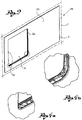
figures 1 and2 show two perspective views of the movement assembly of the present invention, seen from the outside, according to a possible embodiment, illustrating respectively, an advanced or closing configuration and a configuration of at least partial superimposition of the mobile element over the frame opening; - -
figures 3a, 3b and4a, 4b show two enlargements of the areas marked by the circles infigures 1 and2 , respectively; - -
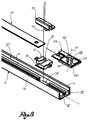
figure 5 shows a perspective view from the inside, partially with separated parts, of the movement device of the present invention, according to a possible embodiment; - -
figure 6 shows an enlargement of the area marked by the circle infigure 5 ; - -
figures 7 and8 show two further enlargements of the extremity portions of the movement device shown infigure 6 ; - -
figures 9a, 10a and 11a show three views from above, of the extremity illustrated infigure 7 , during three functioning steps of the device; - -
figures 9b, 10b and 11b show three views from above, of the extremity illustrated infigure 8 , during the three corresponding functioning steps illustrated infigures 9a, 10a and 11a where, for a clearer representation, the mobile element has been omitted. - With reference to the aforesaid tables,
reference numeral 1 globally indicates, in its totality, a movement device of amobile element 4, such as for example a door, a window or similar, in relation to afixed frame 2, for example of a vehicle. - The
device 1 is in fact suitable, as a nonlimiting example, for the use in both cars, buses, minivans and boats, for the movement of windows, hatchways, trap doors or of sun roofs. - The
fixed frame 2, for example joinable to a vehicle, extends along a plane frame Z and defines within it a frame opening 3, engageable by themobile element 4. - According to a preferred embodiment, the
fixed frame 2 comprises alateral portion 29, which extends along the frame plane Z and is positioned laterally to the frame opening 3. - Preferably, the
lateral portion 29 is at least partially transparent to light. - In other words, according to this embodiment, the
lateral portion 29 comprises a glass pane or similar, if necessary partially obscured, for example to dim the intensity of the sunlight. - The
movement device 1 comprises at least onelongitudinal translation guide 5', 5", joinable to thefixed frame 2 and suitable for enabling the translation of themobile element 4 along a primary translation axis, substantially parallel to the frame plane Z. - This translation takes place from a configuration of at least partial superimposition of the
mobile element 4 with the frame opening 3, for example illustrated infigure 2 , and at least one configuration of non-alignment with the frame opening 3, not shown. - In other words, in the configuration of non-alignment, the
mobile element 4 cannot be seen inside the frame opening 3 by an observer, except for a small segment adjacent to the first extremity rim 4a, in that it is mainly aside in relation to the frame opening 3. - According to an embodiment, the
longitudinal translation guide 5', 5" comprises a first 10 and asecond shoulder 11, which identify at least onetranslation track 12', 12", for the sliding of themobile element 4. - According to a further embodiment, the
longitudinal translation guide 5', 5" also comprises at least onelongitudinal cordon 13, substantially parallel and comprised between the first 10 andsecond shoulder 11. - In other words, the
longitudinal cordon 13 separates the translation guide 5' into twotranslation tracks 12', 12". - According to a further embodiment variation, the first translation track 12' is suitable for co-operating with the
mobile element 4 to perform the aforesaid longitudinal translation. - According to a further embodiment variation, the
second translation track 12", when mounted on thefixed frame 2, is suitable for collecting the condensate forming on thefixed frame 2 or on themobile element 4, and, if necessary, to channel it where desired. - The
movement device 1 further comprises transversal moving means, operatively connected to themobile element 4 so as to allow, when the latter is in the configuration of at least partial superimposition, its movement along a secondary trajectory Y, incident to the primary translation axis X. - This movement takes place between the configuration of at least partial superimposition and an advanced or closing configuration, in which the
mobile element 4 is at least partially engaged in the frame opening 3. - Preferably, in the advanced or closing configuration, the
mobile element 4 is engaged in the frame opening 3 in such a way that the outer surface 4' of the mobile element, that is to say the one facing the frame opening 3, is substantially on a level with thelateral portion 29. - In other words, in such configuration, the outer surface 4' of the
mobile element 4 is substantially at the same height as the outer surface of thelateral portion 29, for the embodiments foreseeing the latter. - In still other words, in the advanced or closing configuration, the
mobile element 4 and the frame constitute a surface which extends continuously, substantially without raised or undercut portions. - Furthermore, the secondary trajectory Y is rectilinear in its final section towards the frame opening 3.
- In other words, the transversal moving means are suitable for moving the first 4a and the
second rim 4b linearly along the secondary trajectory Y. - In still other words, the transversal moving means are suitable for moving the first 4a and the
second rim 4b at least partially simultaneously along the secondary trajectory Y. - In yet other words, the engagement of the
mobile element 4 in the frame opening 3 occurs with a purely linear and non-rotatory movement. - In the embodiment shown in the figures, the secondary trajectory Y is substantially orthogonal to the primary translation axis X.
- According to a preferred embodiment, the transversal moving means are suitable for moving the
mobile element 4 keeping it substantially parallel to the frame plane Z. - In other words, the
mobile element 4 extends in a mobile element plane V, parallel to the frame plane Z. The transversal moving means are therefore suitable for moving themobile element 4 keeping such planes V, Z substantially parallel. - According to a further preferred embodiment, the
mobile element 4 comprises at least a first 4a and asecond rim 4b, reciprocally distanced along the primary translation axis X. The transversal moving means are therefore suitable for simultaneously engaging therims 4a, 4b in the frame opening, bringing them against correspondingvertical uprights 2a, 2b of theframe 2. - The transversal moving means comprise at least one
manoeuvring lever mobile element 4 and rotatable around a rotation axis W, substantially orthogonal to the primary translation axis X, in order to make themobile element 4 translate along the secondary trajectory Y. - In other words, the
manoeuvring lever mobile element 4 is free to translate longitudinally between the configuration of at least partial superimposition and the configuration of non-alignment, and a second position, corresponding to the configuration in which themobile element 4 is conducted from the configuration of at least partial superimposition to the advanced or closing configuration, and vice versa. - Preferably, the
manoeuvring lever - According to one embodiment variation, the
manoeuvring lever - According to the embodiment illustrated in the figures, the first position of the
lever manoeuvring lever manoeuvring lever - Preferably, the rotation axis W is translatable along the primary translation axis X.
- In other words, during moving of the
mobile element 4 between the configuration of at least partial superimposition and the configuration of non-alignment, the rotation axis W moves jointly with themobile element 4. - The
manoeuvring lever lever extremity 19, facing thelongitudinal translation guides 5', 5", comprising a first 20 and asecond rotation pin 21 substantially parallel to each other, the function of which will be explained soon. - According to a preferred embodiment, the transversal moving means comprise at least one
deviator element 6', 6", joined to thelongitudinal translation guide 5', 5" and wherein a transversal groove 9', 9" is obtained. The transversal groove 9', 9" extends along the secondary trajectory Y and is suitable for being engaged by atranslation pin 16', 16", joined to themobile element 4. Moreover, the transversal groove 9', 9" is suitable for piloting thetranslation pin 16', 16" along the secondary trajectory Y, when themanoeuvring lever - The
movement device 1 further comprises at least onefastening element 15', 15" of themobile element 4 to thelongitudinal translation guides 5', 5", bearing thetranslation pin 16', 16". - In a preferred version, the
movement device 1 comprises a first 15' and asecond fastening element 15" spaced along the primary translation axis X, for example positioned substantially besides the first 4a andsecond rim 4b. - Preferably, the
fastening element 15", that is thesecond fastening element 15", has a connecting surface with themobile element 4, and a surface opposite the connection surface comprising abush 17, having an extension mainly orthogonal to the primary translation axis X. - The
first rotation pin 20 is engaged so as to turn in thebush 17 of thefastening element 15". - The transversal moving means comprises at least a pair of
deviator elements 6', 6", spaced along the primary translation axis X, preferably with pitch corresponding to the distance between a pair of translation pins 16', 16", that is the pitch between the first 15' andsecond fastening element 15". - According to a preferred version, the
deviator element 6', 6" comprises a first 7', 7" and asecond wall 8', 8", spaced from each other along the primary translation axis X and defining between them the transversal groove 9', 9", spoken of previously. - According to one embodiment, the first wall 7', 7" of the
deviator element 6', 6" extends between the first 10 and thesecond shoulder 11. - According to a further embodiment, the
second wall 8', 8" of thedeviator element 6', 6" extends between thelongitudinal cordon 13 and thesecond shoulder 11. - In the variations illustrated in
figures 7 and8 , the first wall 7', 7" has an extremity portion of the surface facing the transversal groove 9', 9" that is substantially concave, and thesecond wall 8', 8" has an extremity portion of the surface facing the transversal groove 9', 9" substantially convex. - Preferably, the
longitudinal cordon 13 presents at least a discontinuity or recess 14', 14'" suitable for being engaged by thedeviator element 6', 6". - This way, the
deviator element 6', 6", being positioned inside therecess 14', 14", is prevented from accidentally translating longitudinally. - The transversal moving means comprise a
translation plate slot deviator element 6', 6" along the primary translation axis X. The throughslot translation pin 16', 16" so that to the translation of thetranslation plate translation pin 16', 16" along the transversal groove 9', 9". - In other words, as illustrated in the figures, each
translation pin 16', 16" first engages the throughslot deviator element 6', 6". - As will be explained shortly, these two means cooperate in the movement of the
translation pin 16', 16", and therefore of themobile element 4. - The
translation plate slot 26, distanced along the primary translation axis X. - According to the variation of
figure 6 , the first 25 and the second throughslot 26 are mechanically connected by aconnection element 22. - Preferably, the
translation plate - In other words, the
connection element 22 can be joined todifferent plate extremities slots - In other words again, the
connection element 22 may have a variable axle base so as to be suitable for being adapted to various requirements. - According to a preferred embodiment, the first through
slot 25 extends mainly along an substantially rectilinear direction U, inclined in relation to the primary translation axis X and in relation to the secondary trajectory Y. - According to a further embodiment, the first through
slot 25 has at least oneterminal section 25', 25", extending substantially parallel to the primary translation axis X. - Preferably, the first through
slot 25 comprises a first 25' and second 25" terminal section, corresponding to the stop positions of the translation pin 16' inside theslot 25. - In other words when, for example, the translation pin 16' occupies the first terminal section 25', it is no longer aligned to the axis of the prevalent extension U of the through
slot 25, so that themobile element 4 cannot be pushed from the outside towards the configuration of at least partial superimposition. - In other words, this feature constitutes a simple and reliable anti-intrusion system for prowlers.
- Similarly, the second
terminal section 25" prevents themobile element 4 from approaching the fixedframe 2 at an undesirable moment, causing for example crushing of a child's limbs between them. - According to one version, the extension of the first terminal section 25' is greater than that of the second 25".
- Preferably, the second through
slot 26 extends along a curvilinear trajectory between a first 26' and asecond vertex 26". - In other words, the axis along which the second through
slot 26 extends is a curvilinear axis. - Preferably, the conjunction line between the first 26' and the
second vertex 26" of the second throughslot 26 corresponds substantially to the distance between the first 25' and the secondterminal section 25" of the first throughslot 25, to obtain the at least partially simultaneous movement of therims 4a, 4b in the frame opening 3. - Even more preferably, the contact surfaces of the through
slot translation pin 16', 16" constitute cam surfaces 31, 32, 33, 34, which extend in an inclined manner in relation to the primary translation axis X and to the secondary trajectory Y, in order to push thetranslation pin 16', 16" along the transversal groove 9', 9", as will be shown in the functioning example below. - The
translation plate engagement hole 27 suitable for being engaged in a rotating manner by thesecond rotation pin 21 of the manoeuvringlever - Preferably, the extension axis of the
engagement hole 27 is parallel and coincident with the rotation axis W. - According to one embodiment, the
device 1 comprises stopping means, suitable for limiting the translation of themobile element 4 along the primary translation axis X. - In other words, the stopping means enable the translation of the
mobile element 4 to be stopped in intermediate positions, between the configuration of at least partial superimposition and the configuration of non-alignment. - For example, the stopping means comprise the
second rotation pin 21 of the manoeuvringlever Such pin 21 is axially mobile along the rotation axis W, so as to reversibly engage at least a stop hole (not shown) positioned on thelongitudinal translation guide 5', 5", preferably on the underside. - In an initial functioning step, the
rotation pin 21 is engaged in a first stop hole of thetranslation guide 5', 5" and the mobile element is prevented from its longitudinal translation. - In a subsequent step, the manoeuvring
lever second rotation pin 21 from the first stop hole. - In a subsequent step, the
mobile element 4 is moved longitudinally along the axis X, for example towards the configuration of at least partial superimposition. When therotation pin 21 encounters a subsequent stop hole, it engages the latter so as to stop the longitudinal translation of themobile element 4. - According to one embodiment variation, the extremity of the manoeuvring
lever 18 opposite that bearing therotation pin 21 comprises elastic means, for example a spring, suitable for holding therotation pin 21 against thetranslation guide 5', 5" or suitable for engaging it in the stop holes. - The present invention furthermore relates to a
movement assembly 28. - The
movement assembly 28 comprises a fixedframe 2, for example of a vehicle, which extends in a frame plane Z and defining within it a frame opening 3, amobile element 4, such as for example a door, a window or similar, in relation to a fixedframe 2 and suitable for being engaged in the frame opening 3, and at least onemovement device 1, according to any of the previously illustrated embodiments. - According to a preferred version, the fixed
frame 2 comprises alateral portion 29, which extends in the frame plane Z and which is positioned laterally to the frame opening 3. - Preferably, the
lateral portion 29 is at least partially transparent to the light. - The present invention lastly relates to a vehicle, such as a motor vehicle or a boat, comprising a
movement device 1 according to any of the previous embodiments, or comprising amovement assembly 28 according to one of the aforesaid embodiments. - The functioning of the device just illustrated will now be described.
- For ease of exposition, the functioning of the portion shown in the exploded view in
figure 6 only will be described, that is to say of that relative to the first longitudinal translation guide 5'. However, for the embodiments which foresee a pair of guides, the functioning of the secondlongitudinal translation guide 5" is the same as the first 5'. - Furthermore, a device comprising a pair of translation pins 16', 16" will be considered. However, the functioning principle is substantially the same for a larger number of pins.
- The
mobile element 4 is initially positioned in the configuration of non-alignment with the frame opening 3. - In such configuration, the
mobile element 4 cannot be seen by an observer in the frame opening 3, except for a small segment adjacent to the first rim 4a, in that it is mainly aside from the frame opening 3, and is mainly hidden by thelateral portion 29, in those embodiments which foresee it. - In a subsequent functioning step, illustrated in
figures 9a and 9b , themobile element 4 is moved along the longitudinal translation guide 5', along the primary translation axis X, between the configuration of non-alignment and the configuration of at least partial superimposition. - During this step, the translation pins 16', 16", joined to the
mobile element 4, slide along the longitudinal translation guide 5' and, specifically, along the translation track 12'. - In other words, the translation pins 16', 16" are guided by the first 10 and by the
second shoulder 11, or by thefirst shoulder 10 and by thelongitudinal cordon 13, parallel to the frame plane Z. - Moreover, in this step, the manoeuvring
lever slots translation plate terminal section 25" and the first vertex 26'. - In this step, the
translation plate mobile element 4. - The translation along the primary translation axis X is interrupted when the translation pins 16', 16" go in abutment against the
respective deviator element 6', 6", engaged bysuch pins 16', 16" emerging from the underside of the throughslots deviator elements 6', 6" thus act as stop elements. - In other words, the translation along the axis X terminates when the translation pins 16', 16" are substantially positioned at the entrance of the respective transversal groove 9', 9" of the
deviator element 6', 6". - Similarly, according to an advantageous embodiment, in the configuration of non-alignment, the stop position is reached when the translation pin 16' goes in abutment against the
surface 30 of thedeviator element 6", opposite that defining the transversal groove 9". - In a subsequent step, the manoeuvring
lever mobile element 4 between a configuration of at least partial superimposition (shown infigure 2 ) and an advanced or closing configuration (shown infigure 1 ). - This way, the
second rotation pin 21 of the manoeuvringlever engagement hole 27, while thefirst rotation pin 20 of thelever bush 17, joined to thetranslation pin 16", moving the translation plate in relation to thedeviator element 6', 6". - Specifically, the translation of the
translation plate deviator element 6', 6" is provoked by the longitudinal translation of thesecond rotation pin 21 and of the relative axis of rotation W, as thetranslation pin 16" is prevented by thesecond wall 8" of thedeviator element 6" from translating according to the direction of rotation of thelever - In fact, when the rotation of the manoeuvring
lever translation pin 16" finds itself against thesecond wall 8" and begins to engage the transversal groove 9" along the secondary trajectory Y. - As illustrated previously, the contact surfaces of the through
slot translation pin 16', 16" constitute in fact cam surfaces 31, 32, 33, 34. In this step thefirst cam surface 31 of theslot 26 co-operates with thesecond wall 8" of thedeviator element 6", in order to push thetranslation pin 16" along the transversal groove 9" in the reciprocal movement. - Similarly, the rotation of the manoeuvring
lever connection element 22 at theother extremity 23 of thetranslation plate - In correspondence of
such extremity 23, thesecond cam surface 32 of theslot 25 co-operates with the first wall 7' of the deviator element 6', so as to push the translation pin 16' along the transversal groove 9'. - As shown in
figures 10a and 10b , thetranslation pin 16" begins to run inside the transversal groove 9", at the same time moving along the second throughslot 26, and the translation pin 16' begins to run inside the transversal groove 9', at the same time moving along the first throughslot 25, bringing therims 4a, 4b of themobile element 4 closer to the vertical uprights 2a, 2b. of theframe 2. - Lastly, having completed the rotation of the manoeuvring
lever figures 11a and 11b , themobile element 4 is at least partially engaged in the frame opening 3, as eachtranslation pin 16', 16" is positioned at the terminal section 25' and thesecond vertex 26" of thetranslation plate deviator element 6', 6", preferably against thesecond shoulder 11. - During the disengagement of the
mobile element 4 from the frame opening 3, performed by rotating the manoeuvringlever - Innovatively, the device and assembly of the present invention may be used with mobile elements of any thickness, guaranteeing functioning and reliability in any case. In fact, thanks to the use of the guiding means of the mobile element as described above, the transversal movement of the same is performed by making the mobile element enter the frame opening with a simultaneous movement of the opposite rims, that is of pure translation (at least along the terminal section of the entrance trajectory), which enables use of mobile elements of any thickness. The absence of rotatory movements in fact, does not limit neither the longitudinal extension nor the encumbrance of the mobile element to be used with the present device.
- Furthermore, thanks to the movement of pure translation of the rims of the mobile element into the frame opening, the device runs substantially flush with the uprights of the frame, making it possible to reduce (or even eliminate) the presence of sealing means between the frame and the mobile element.
- Advantageously, the device of the present invention, is highly versatile, permitting easy assembly and a number of applications, for both land vehicles, boats and habitations.
- Advantageously, the disposition of the mobile element in the closing configuration, substantially at the same height as the lateral portion permits a considerable reduction of the noise produced by the vehicle when moving, because the air hitting such surfaces passes over them without encountering obstacles and thus without generating annoying whistlings.
- Furthermore, this way any water accumulation, for example rainwater, inside the frame opening is prevented.
- Advantageously, the presence of at least one recess along the longitudinal cordon ensures that the deviator element remains in its seat without the use of special, additional fastening means.
- Advantageously, the translation plate is composed of three separate components, so that the parts most subject to wear can be replaced as required.
- Moreover, the possibility of replacing the connection element with another with a bigger or smaller axle base, means that the translation plate can be adapted to diverse manufacturing needs.
- Advantageously, the presence of at least one through slot having terminal portions extending longitudinally further allows security against intrusion from the outside, especially by burglars or prowlers.
- Moreover, the presence of a through slot having terminal portions extending longitudinally guarantees greater functioning safety, preventing the accidental crushing of user's extremities.
- A person skilled in the art may make modifications, adaptations and substitutions to the embodiments of the device and of the assembly described above so as to satisfy contingent requirements, while remaining within the scope of protection as defined by the following claims.
- For example, the replacement of the longitudinal translation guide previously illustrated with a guide having a different transversal cross-section, but fulfilling the same function, does not entail any inventive effort.
Claims (13)
- Movement device (1) of a mobile element (4) in relation to a fixed frame (2) developing in a frame plane (Z) and defining within it a frame opening (3) engageable by the mobile element (4),
said device (1) comprising:- at least one longitudinal translation guide (5', 5"), joinable to the fixed frame (2) and suitable for allowing the translation of the mobile element (4) along a primary translation axis (X), substantially parallel to the frame plane (Z), between a configuration of at least partial superimposition of the mobile element (4) with the frame opening (3), and at least one configuration of non-alignment with the opening (3); and- transversal moving means, operatively connected to the mobile element (4) so as to enable, when the latter is in the configuration of at least partial superimposition, its movement along a secondary trajectory (Y), incident to the primary translation axis (X) and substantially rectilinear at least in its terminal section towards the frame opening (3), between the configuration of at least partial superimposition and an advanced or closing configuration, wherein the mobile element (4) is at least partially engaged in the frame opening (3), wherein the transversal moving means comprise:i) at least one manoeuvring lever (18, 19), operatively connected to the mobile element (4) and rotatable around a rotation axis (W), substantially orthogonal to the primary translation axis (X) in order to make the mobile element (4) translate along the secondary trajectory (Y);ii) at least two deviator elements (6', 6"), joined to the longitudinal translation guide (5', 5") and wherein a transversal groove (9', 9") has been obtained, extending along the secondary trajectory (Y) and engageable by translation pins (16', 16") joined to the mobile element (4), said transversal groove (9', 9") being suitable for driving the translation pin (16', 16") along the secondary trajectory (Y), when the manoeuvring lever (18, 19) is actuated;iii) a translation plate (22, 23, 24) comprising through slots (25, 26), suitable for translating in relation to the deviator elements (6', 6") along the primary translation axis (X), and each engaged by a translation pin (16', 16") so that to the translation of the translation plate (22, 23, 24) corresponds the movement of the translation pins (16', 16") along the transversal grooves (9', 9");said device being characterized in comprising:iv) at least one fastening element (15', 15") of the mobile element (4) to the longitudinal translation guide (5', 5"), bearing a translation pin (16', 16"), said fastening element (15") having a connection surface with the mobile element (4), and a surface opposite the connection surface comprising a bush (17), wherein the bush (17) extends mainly in an orthogonal direction to the primary translation axis (X), wherein the manoeuvring lever (18, 19) comprises at least one lever extremity (19), facing the longitudinal translation guide (5', 5"), comprising substantially parallel first (20) and second (21) rotation pins, the first rotation pin (20) of the lever (18, 19) rotating inside said bush (17) joined to a translation pin (16") integral to the mobile element (4), the second rotation pin (21) rotating inside an engagement hole (27) of the translation plate (22, 23, 24) to move the translation plate in relation to the deviator elements (6', 6"). - Device (1) according to the previous claim, wherein the manoeuvring lever (18, 19) is rotatable to move the translation plate (22, 23, 24) in relation to the deviator elements (6', 6").
- Device (1) according to claim 1 or 2, wherein the manoeuvring lever (18, 19) is actuable manually.
- Device (1) according to any of the previous claims, wherein the deviator elements (6', 6") act as stop elements to interrupt translation of the mobile element (4) along the primary translation axis (X), said pins (16', 16") emerging from the underside of the through slots (25, 26) to engage and abut against the respective deviator element (6', 6").
- Device (1) according to any of the previous claims, wherein the contact surfaces of the through slots (25, 26) with the translation pins (16', 16") constitute cam surfaces (31, 32, 33, 34), which extend in an inclined manner in relation to the primary translation axis (X) and to the secondary trajectory (Y), in order to push the translation pins (16', 16") along the transversal grooves (9', 9").
- Device (1) according to any of the previous claims, wherein the translation along the axis (X) terminates when the translation pins (16', 16") are substantially positioned at the entrance of the respective transversal groove (9', 9") of the deviator element (6', 6").
- Device (1) according to any of the previous claims, wherein each deviator element (6', 6") comprises a first (7', 7") and a second wall (8', 8"), distanced from each other along the primary translation axis (X) and defining between them the transversal groove (9', 9").
- Device (1) according to the previous claim, wherein the longitudinal translation guide (5', 5") comprises a first (10) and a second shoulder (11), identifying at least one translation track (12', 12") therebetween, and wherein the first wall (7', 7") of the deviator element (6', 6") extends between said first (10) and second shoulder (11).
- Device (1) according to any of the previous claims, wherein the translation plate (22, 23, 24) comprises a first (25) and a second through slot (26), distanced along the primary translation axis (X).
- Device (1) according to the previous claim, wherein the first through slot (25) presents at least one terminal section (25', 25"), extending substantially parallel to the primary translation axis (X).
- Device (1) according to any of the previous claims, wherein the development axis of the engagement hole (27) is parallel and coincident with the rotation axis (W).
- Movement assembly (28) comprising:- a fixed frame (2) developing in a frame plane (Z) and identifying within it a frame opening (3);wherein the fixed frame (2) comprises a lateral portion (29), at least partially transparent to the light, extending in the frame plane (Z) and positioned laterally to the frame opening (3);- an element (4) mobile in relation to a fixed frame (2) and engageable in the frame opening (3); and- at least one movement device (1) according to any of the claims from 1 to 11.
- Vehicle, such as a motor vehicle or a boat, comprising a device (1) according to any of the claims from 1 to 11, or a movement assembly (28) according to the previous claim.
Priority Applications (2)
| Application Number | Priority Date | Filing Date | Title |
|---|---|---|---|
| EP13199714.0A EP2712992B1 (en) | 2008-09-19 | 2008-09-19 | Movement device and assembly |
| HUE13199714A HUE029306T2 (en) | 2008-09-19 | 2008-09-19 | Movement device and assembly |
Applications Claiming Priority (3)
| Application Number | Priority Date | Filing Date | Title |
|---|---|---|---|
| EP08876052.5A EP2324177B1 (en) | 2008-09-19 | 2008-09-19 | Movement device and assembly |
| EP13199714.0A EP2712992B1 (en) | 2008-09-19 | 2008-09-19 | Movement device and assembly |
| PCT/IT2008/000604 WO2010032273A1 (en) | 2008-09-19 | 2008-09-19 | Movement device and assembly |
Related Parent Applications (1)
| Application Number | Title | Priority Date | Filing Date |
|---|---|---|---|
| EP08876052.5A Division EP2324177B1 (en) | 2008-09-19 | 2008-09-19 | Movement device and assembly |
Publications (2)
| Publication Number | Publication Date |
|---|---|
| EP2712992A1 EP2712992A1 (en) | 2014-04-02 |
| EP2712992B1 true EP2712992B1 (en) | 2016-07-06 |
Family
ID=40599620
Family Applications (2)
| Application Number | Title | Priority Date | Filing Date |
|---|---|---|---|
| EP08876052.5A Active EP2324177B1 (en) | 2008-09-19 | 2008-09-19 | Movement device and assembly |
| EP13199714.0A Active EP2712992B1 (en) | 2008-09-19 | 2008-09-19 | Movement device and assembly |
Family Applications Before (1)
| Application Number | Title | Priority Date | Filing Date |
|---|---|---|---|
| EP08876052.5A Active EP2324177B1 (en) | 2008-09-19 | 2008-09-19 | Movement device and assembly |
Country Status (5)
| Country | Link |
|---|---|
| US (1) | US8469437B2 (en) |
| EP (2) | EP2324177B1 (en) |
| HU (1) | HUE029306T2 (en) |
| PL (2) | PL2712992T3 (en) |
| WO (1) | WO2010032273A1 (en) |
Families Citing this family (11)
| Publication number | Priority date | Publication date | Assignee | Title |
|---|---|---|---|---|
| US9027282B2 (en) * | 2008-11-03 | 2015-05-12 | Guardian Industries Corp. | Modifiable slider glass assemblies for utility cabs and vehicles, and/or methods of making the same |
| EP2277729B1 (en) * | 2009-06-19 | 2014-11-19 | Advanced Comfort Systems France SAS - ACS France | Device for closing an opening made in the body of an automobile comprising balancing means, and corresponding automobile |
| US8794688B2 (en) * | 2012-01-24 | 2014-08-05 | Chrysler Group Llc | Door assembly for a vehicle |
| US9574533B2 (en) * | 2013-06-13 | 2017-02-21 | General Electric Company | Fuel injection nozzle and method of manufacturing the same |
| GB201614259D0 (en) * | 2016-08-22 | 2016-10-05 | Vehicle Window Centre Ltd | Closure apparatus and method of use thereof |
| JP6491801B2 (en) * | 2016-09-09 | 2019-03-27 | 八千代工業株式会社 | Power sliding window |
| CN109690007B (en) * | 2016-09-09 | 2020-01-10 | 八千代工业株式会社 | Power sliding window |
| CN112334628B (en) * | 2018-07-31 | 2021-09-24 | 八千代工业株式会社 | Automatic opening and closing sliding window |
| EP3999700A1 (en) * | 2019-07-15 | 2022-05-25 | Lippert Components Inc. | Sliding window assembly |
| KR20240144226A (en) * | 2022-02-03 | 2024-10-02 | 어드밴스드 컴포트 시스템스 프랑스 에스에이에스-에이씨에스 프랑스 | A device for closing an opening made in a body of a vehicle, and a corresponding vehicle |
| US12590482B1 (en) * | 2024-10-01 | 2026-03-31 | Aisin Corporation | Sliding window assembly with flush-closing moving panel |
Family Cites Families (15)
| Publication number | Priority date | Publication date | Assignee | Title |
|---|---|---|---|---|
| US1712562A (en) * | 1927-02-18 | 1929-05-14 | Martin Parry Corp | Vehicle door |
| DE1248488B (en) * | 1960-01-26 | 1967-08-24 | Volkswagenwerk Ag | Sliding door for motor vehicles suspended in three points |
| US3216716A (en) * | 1961-12-26 | 1965-11-09 | Lunde | Rolling hatch covers |
| JPS5387426A (en) * | 1977-01-12 | 1978-08-01 | Nissan Motor Co Ltd | Apparatus for sliding slide door for vehicle |
| CH626941A5 (en) * | 1978-01-18 | 1981-12-15 | Lanz & Marti Ag | Sliding-door lock on a body of a commercial vehicle or trailer |
| US5467557A (en) * | 1993-12-15 | 1995-11-21 | Jones; Edgar W. | Window construction and method of making the same |
| US5613323A (en) * | 1995-01-19 | 1997-03-25 | Excel Industries, Inc. | Cable drive assembly for a window |
| US5992097A (en) * | 1997-05-16 | 1999-11-30 | Aisin Seiki Kabushiki Kaisha | Sliding door structure |
| US6328374B1 (en) * | 2000-06-21 | 2001-12-11 | Ford Global Technologies, Inc. | Fully-openable slidable vehicle door assembly |
| FR2833209B1 (en) * | 2001-12-10 | 2005-06-24 | Wagon Automotive Snc | DEVICE FOR SEALING A BAY MADE IN THE BODY OF A VEHICLE, AND VEHICLE THEREFOR |
| DE10343216A1 (en) * | 2003-09-18 | 2005-04-14 | Dura Automotive Plettenberg Entwicklungs- Und Vertriebs Gmbh | Composite component, in particular for a sliding window of a motor vehicle |
| US7395631B2 (en) * | 2004-01-09 | 2008-07-08 | Agc Automotive Americas Co. | Sliding window assembly and a carrier component |
| US7437852B2 (en) * | 2005-02-04 | 2008-10-21 | Dura Global Technologies, Inc. | Sliding window apparatus |
| US20070234644A1 (en) * | 2006-03-31 | 2007-10-11 | Jurgen Jaeger | Sliding window assembly |
| US7641265B2 (en) * | 2006-10-30 | 2010-01-05 | Pilkington North America, Inc. | Vehicle window assembly with horizontal slider |
-
2008
- 2008-09-19 HU HUE13199714A patent/HUE029306T2/en unknown
- 2008-09-19 PL PL13199714.0T patent/PL2712992T3/en unknown
- 2008-09-19 WO PCT/IT2008/000604 patent/WO2010032273A1/en not_active Ceased
- 2008-09-19 EP EP08876052.5A patent/EP2324177B1/en active Active
- 2008-09-19 EP EP13199714.0A patent/EP2712992B1/en active Active
- 2008-09-19 PL PL08876052T patent/PL2324177T3/en unknown
- 2008-09-19 US US13/119,873 patent/US8469437B2/en active Active
Also Published As
| Publication number | Publication date |
|---|---|
| EP2712992A1 (en) | 2014-04-02 |
| US20110173893A1 (en) | 2011-07-21 |
| WO2010032273A1 (en) | 2010-03-25 |
| PL2712992T3 (en) | 2016-11-30 |
| EP2324177A1 (en) | 2011-05-25 |
| HUE029306T2 (en) | 2017-02-28 |
| EP2324177B1 (en) | 2014-01-01 |
| PL2324177T3 (en) | 2014-07-31 |
| US8469437B2 (en) | 2013-06-25 |
Similar Documents
| Publication | Publication Date | Title |
|---|---|---|
| EP2324177B1 (en) | Movement device and assembly | |
| US8562063B2 (en) | Device for closing off an opening formed in the bodywork of a vehicle, with a guide element and slide forming a shuttle, and corresponding vehicle | |
| EP2089244B1 (en) | Vehicle window assembly with horizontal slider | |
| US5724771A (en) | Window assembly with unitary anti-theft projection | |
| US8186103B2 (en) | Sliding window assembly | |
| US20120017517A1 (en) | Electrical door - locking device | |
| CA2942126A1 (en) | Powered actuator | |
| SG174936A1 (en) | Electric door-locking apparatus, and electric door comprising same | |
| EP3439938B1 (en) | Lock mechanism for improved door panel seal | |
| US20090301821A1 (en) | Elevator entrance apparatus | |
| KR20200063169A (en) | Electric double inner swing door and inner swing door driving device | |
| EP3168404B1 (en) | Door, window or french window assembly | |
| CA2988151A1 (en) | Sliding operating handle | |
| RU2662696C2 (en) | Fitting for at least liftable, but preferably also slidable window or door leaf | |
| WO2014082312A1 (en) | Device for closing off an opening formed in the bodywork of an automobile vehicle, and corresponding vehicle | |
| US20100115847A1 (en) | Flush type window drive mechanism | |
| KR101493000B1 (en) | Automatic fire door having anti-panic function | |
| CA2580635C (en) | Floor lock | |
| US20250163741A1 (en) | Device for closing off an opening made in the body of a vehicle, and corresponding vehicle | |
| CN109296293B (en) | Side pressure attaches frame and uses its sliding door and window | |
| KR101372577B1 (en) | Door roller assembly for lift-windows | |
| JPH03217323A (en) | Sealing device for window of automobile door | |
| EP0844123B1 (en) | A side part for a motor vehicle, particularly a coupé, having longitudinally-slidable doors | |
| KR20210001254U (en) | Emergency notification device for car | |
| DE10115699B4 (en) | Motorically movable motor vehicle closing part, in particular motor vehicle side window and / or motor vehicle sunroof |
Legal Events
| Date | Code | Title | Description |
|---|---|---|---|
| PUAI | Public reference made under article 153(3) epc to a published international application that has entered the european phase |
Free format text: ORIGINAL CODE: 0009012 |
|
| AC | Divisional application: reference to earlier application |
Ref document number: 2324177 Country of ref document: EP Kind code of ref document: P |
|
| AK | Designated contracting states |
Kind code of ref document: A1 Designated state(s): AT BE BG CH CY CZ DE DK EE ES FI FR GB GR HR HU IE IS IT LI LT LU LV MC MT NL NO PL PT RO SE SI SK TR |
|
| 17P | Request for examination filed |
Effective date: 20140917 |
|
| RBV | Designated contracting states (corrected) |
Designated state(s): AT BE BG CH CY CZ DE DK EE ES FI FR GB GR HR HU IE IS IT LI LT LU LV MC MT NL NO PL PT RO SE SI SK TR |
|
| 17Q | First examination report despatched |
Effective date: 20150202 |
|
| GRAP | Despatch of communication of intention to grant a patent |
Free format text: ORIGINAL CODE: EPIDOSNIGR1 |
|
| INTG | Intention to grant announced |
Effective date: 20160217 |
|
| GRAS | Grant fee paid |
Free format text: ORIGINAL CODE: EPIDOSNIGR3 |
|
| GRAA | (expected) grant |
Free format text: ORIGINAL CODE: 0009210 |
|
| AC | Divisional application: reference to earlier application |
Ref document number: 2324177 Country of ref document: EP Kind code of ref document: P |
|
| AK | Designated contracting states |
Kind code of ref document: B1 Designated state(s): AT BE BG CH CY CZ DE DK EE ES FI FR GB GR HR HU IE IS IT LI LT LU LV MC MT NL NO PL PT RO SE SI SK TR |
|
| REG | Reference to a national code |
Ref country code: GB Ref legal event code: FG4D |
|
| REG | Reference to a national code |
Ref country code: AT Ref legal event code: REF Ref document number: 810853 Country of ref document: AT Kind code of ref document: T Effective date: 20160715 Ref country code: CH Ref legal event code: NV Representative=s name: MICHELI AND CIE SA, CH Ref country code: CH Ref legal event code: EP |
|
| REG | Reference to a national code |
Ref country code: IE Ref legal event code: FG4D |
|
| REG | Reference to a national code |
Ref country code: NL Ref legal event code: FP |
|
| REG | Reference to a national code |
Ref country code: DE Ref legal event code: R096 Ref document number: 602008045044 Country of ref document: DE |
|
| REG | Reference to a national code |
Ref country code: SE Ref legal event code: TRGR |
|
| REG | Reference to a national code |
Ref country code: FR Ref legal event code: PLFP Year of fee payment: 9 |
|
| REG | Reference to a national code |
Ref country code: LT Ref legal event code: MG4D |
|
| REG | Reference to a national code |
Ref country code: AT Ref legal event code: MK05 Ref document number: 810853 Country of ref document: AT Kind code of ref document: T Effective date: 20160706 |
|
| PG25 | Lapsed in a contracting state [announced via postgrant information from national office to epo] |
Ref country code: LT Free format text: LAPSE BECAUSE OF FAILURE TO SUBMIT A TRANSLATION OF THE DESCRIPTION OR TO PAY THE FEE WITHIN THE PRESCRIBED TIME-LIMIT Effective date: 20160706 Ref country code: NO Free format text: LAPSE BECAUSE OF FAILURE TO SUBMIT A TRANSLATION OF THE DESCRIPTION OR TO PAY THE FEE WITHIN THE PRESCRIBED TIME-LIMIT Effective date: 20161006 Ref country code: HR Free format text: LAPSE BECAUSE OF FAILURE TO SUBMIT A TRANSLATION OF THE DESCRIPTION OR TO PAY THE FEE WITHIN THE PRESCRIBED TIME-LIMIT Effective date: 20160706 Ref country code: IS Free format text: LAPSE BECAUSE OF FAILURE TO SUBMIT A TRANSLATION OF THE DESCRIPTION OR TO PAY THE FEE WITHIN THE PRESCRIBED TIME-LIMIT Effective date: 20161106 |
|
| PG25 | Lapsed in a contracting state [announced via postgrant information from national office to epo] |
Ref country code: LV Free format text: LAPSE BECAUSE OF FAILURE TO SUBMIT A TRANSLATION OF THE DESCRIPTION OR TO PAY THE FEE WITHIN THE PRESCRIBED TIME-LIMIT Effective date: 20160706 Ref country code: ES Free format text: LAPSE BECAUSE OF FAILURE TO SUBMIT A TRANSLATION OF THE DESCRIPTION OR TO PAY THE FEE WITHIN THE PRESCRIBED TIME-LIMIT Effective date: 20160706 Ref country code: AT Free format text: LAPSE BECAUSE OF FAILURE TO SUBMIT A TRANSLATION OF THE DESCRIPTION OR TO PAY THE FEE WITHIN THE PRESCRIBED TIME-LIMIT Effective date: 20160706 Ref country code: PT Free format text: LAPSE BECAUSE OF FAILURE TO SUBMIT A TRANSLATION OF THE DESCRIPTION OR TO PAY THE FEE WITHIN THE PRESCRIBED TIME-LIMIT Effective date: 20161107 Ref country code: GR Free format text: LAPSE BECAUSE OF FAILURE TO SUBMIT A TRANSLATION OF THE DESCRIPTION OR TO PAY THE FEE WITHIN THE PRESCRIBED TIME-LIMIT Effective date: 20161007 |
|
| REG | Reference to a national code |
Ref country code: HU Ref legal event code: AG4A Ref document number: E029306 Country of ref document: HU |
|
| REG | Reference to a national code |
Ref country code: DE Ref legal event code: R097 Ref document number: 602008045044 Country of ref document: DE |
|
| PG25 | Lapsed in a contracting state [announced via postgrant information from national office to epo] |
Ref country code: MC Free format text: LAPSE BECAUSE OF FAILURE TO SUBMIT A TRANSLATION OF THE DESCRIPTION OR TO PAY THE FEE WITHIN THE PRESCRIBED TIME-LIMIT Effective date: 20160706 Ref country code: EE Free format text: LAPSE BECAUSE OF FAILURE TO SUBMIT A TRANSLATION OF THE DESCRIPTION OR TO PAY THE FEE WITHIN THE PRESCRIBED TIME-LIMIT Effective date: 20160706 Ref country code: RO Free format text: LAPSE BECAUSE OF FAILURE TO SUBMIT A TRANSLATION OF THE DESCRIPTION OR TO PAY THE FEE WITHIN THE PRESCRIBED TIME-LIMIT Effective date: 20160706 |
|
| PLBE | No opposition filed within time limit |
Free format text: ORIGINAL CODE: 0009261 |
|
| STAA | Information on the status of an ep patent application or granted ep patent |
Free format text: STATUS: NO OPPOSITION FILED WITHIN TIME LIMIT |
|
| PG25 | Lapsed in a contracting state [announced via postgrant information from national office to epo] |
Ref country code: BG Free format text: LAPSE BECAUSE OF FAILURE TO SUBMIT A TRANSLATION OF THE DESCRIPTION OR TO PAY THE FEE WITHIN THE PRESCRIBED TIME-LIMIT Effective date: 20161006 Ref country code: DK Free format text: LAPSE BECAUSE OF FAILURE TO SUBMIT A TRANSLATION OF THE DESCRIPTION OR TO PAY THE FEE WITHIN THE PRESCRIBED TIME-LIMIT Effective date: 20160706 Ref country code: SK Free format text: LAPSE BECAUSE OF FAILURE TO SUBMIT A TRANSLATION OF THE DESCRIPTION OR TO PAY THE FEE WITHIN THE PRESCRIBED TIME-LIMIT Effective date: 20160706 |
|
| 26N | No opposition filed |
Effective date: 20170407 |
|
| REG | Reference to a national code |
Ref country code: IE Ref legal event code: MM4A |
|
| PG25 | Lapsed in a contracting state [announced via postgrant information from national office to epo] |
Ref country code: IE Free format text: LAPSE BECAUSE OF NON-PAYMENT OF DUE FEES Effective date: 20160919 |
|
| PG25 | Lapsed in a contracting state [announced via postgrant information from national office to epo] |
Ref country code: LU Free format text: LAPSE BECAUSE OF NON-PAYMENT OF DUE FEES Effective date: 20160919 Ref country code: SI Free format text: LAPSE BECAUSE OF FAILURE TO SUBMIT A TRANSLATION OF THE DESCRIPTION OR TO PAY THE FEE WITHIN THE PRESCRIBED TIME-LIMIT Effective date: 20160706 |
|
| REG | Reference to a national code |
Ref country code: FR Ref legal event code: PLFP Year of fee payment: 10 |
|
| PG25 | Lapsed in a contracting state [announced via postgrant information from national office to epo] |
Ref country code: CY Free format text: LAPSE BECAUSE OF FAILURE TO SUBMIT A TRANSLATION OF THE DESCRIPTION OR TO PAY THE FEE WITHIN THE PRESCRIBED TIME-LIMIT Effective date: 20160706 |
|
| PG25 | Lapsed in a contracting state [announced via postgrant information from national office to epo] |
Ref country code: MT Free format text: LAPSE BECAUSE OF NON-PAYMENT OF DUE FEES Effective date: 20160930 |
|
| REG | Reference to a national code |
Ref country code: FR Ref legal event code: PLFP Year of fee payment: 11 |
|
| PGFP | Annual fee paid to national office [announced via postgrant information from national office to epo] |
Ref country code: PL Payment date: 20180903 Year of fee payment: 11 Ref country code: CH Payment date: 20180926 Year of fee payment: 11 Ref country code: CZ Payment date: 20180917 Year of fee payment: 11 Ref country code: BE Payment date: 20180925 Year of fee payment: 11 |
|
| PGFP | Annual fee paid to national office [announced via postgrant information from national office to epo] |
Ref country code: NL Payment date: 20180925 Year of fee payment: 11 |
|
| REG | Reference to a national code |
Ref country code: FI Ref legal event code: MAE |
|
| PG25 | Lapsed in a contracting state [announced via postgrant information from national office to epo] |
Ref country code: SE Free format text: LAPSE BECAUSE OF NON-PAYMENT OF DUE FEES Effective date: 20190920 Ref country code: FI Free format text: LAPSE BECAUSE OF NON-PAYMENT OF DUE FEES Effective date: 20190919 |
|
| REG | Reference to a national code |
Ref country code: SE Ref legal event code: EUG |
|
| REG | Reference to a national code |
Ref country code: NL Ref legal event code: MM Effective date: 20191001 |
|
| PG25 | Lapsed in a contracting state [announced via postgrant information from national office to epo] |
Ref country code: CZ Free format text: LAPSE BECAUSE OF NON-PAYMENT OF DUE FEES Effective date: 20190919 |
|
| REG | Reference to a national code |
Ref country code: CH Ref legal event code: PL |
|
| PG25 | Lapsed in a contracting state [announced via postgrant information from national office to epo] |
Ref country code: NL Free format text: LAPSE BECAUSE OF NON-PAYMENT OF DUE FEES Effective date: 20191001 Ref country code: CH Free format text: LAPSE BECAUSE OF NON-PAYMENT OF DUE FEES Effective date: 20190930 Ref country code: LI Free format text: LAPSE BECAUSE OF NON-PAYMENT OF DUE FEES Effective date: 20190930 |
|
| REG | Reference to a national code |
Ref country code: BE Ref legal event code: MM Effective date: 20190930 |
|
| PG25 | Lapsed in a contracting state [announced via postgrant information from national office to epo] |
Ref country code: BE Free format text: LAPSE BECAUSE OF NON-PAYMENT OF DUE FEES Effective date: 20190930 |
|
| PGFP | Annual fee paid to national office [announced via postgrant information from national office to epo] |
Ref country code: FR Payment date: 20200928 Year of fee payment: 13 |
|
| PGFP | Annual fee paid to national office [announced via postgrant information from national office to epo] |
Ref country code: IT Payment date: 20200922 Year of fee payment: 13 |
|
| PGFP | Annual fee paid to national office [announced via postgrant information from national office to epo] |
Ref country code: HU Payment date: 20201007 Year of fee payment: 13 |
|
| PG25 | Lapsed in a contracting state [announced via postgrant information from national office to epo] |
Ref country code: HU Free format text: LAPSE BECAUSE OF NON-PAYMENT OF DUE FEES Effective date: 20210920 Ref country code: FR Free format text: LAPSE BECAUSE OF NON-PAYMENT OF DUE FEES Effective date: 20210930 |
|
| PG25 | Lapsed in a contracting state [announced via postgrant information from national office to epo] |
Ref country code: PL Free format text: LAPSE BECAUSE OF NON-PAYMENT OF DUE FEES Effective date: 20190919 |
|
| PG25 | Lapsed in a contracting state [announced via postgrant information from national office to epo] |
Ref country code: IT Free format text: LAPSE BECAUSE OF NON-PAYMENT OF DUE FEES Effective date: 20210919 |
|
| P01 | Opt-out of the competence of the unified patent court (upc) registered |
Effective date: 20230524 |
|
| PGFP | Annual fee paid to national office [announced via postgrant information from national office to epo] |
Ref country code: GB Payment date: 20240924 Year of fee payment: 17 |
|
| PGFP | Annual fee paid to national office [announced via postgrant information from national office to epo] |
Ref country code: DE Payment date: 20250926 Year of fee payment: 18 |
|
| PGFP | Annual fee paid to national office [announced via postgrant information from national office to epo] |
Ref country code: TR Payment date: 20250904 Year of fee payment: 18 |