EP2712830A2 - Traverse arm and yarn winding machine including the same - Google Patents
Traverse arm and yarn winding machine including the same Download PDFInfo
- Publication number
- EP2712830A2 EP2712830A2 EP13185553.8A EP13185553A EP2712830A2 EP 2712830 A2 EP2712830 A2 EP 2712830A2 EP 13185553 A EP13185553 A EP 13185553A EP 2712830 A2 EP2712830 A2 EP 2712830A2
- Authority
- EP
- European Patent Office
- Prior art keywords
- arm body
- traverse
- arm
- protrusion
- yarn
- Prior art date
- Legal status (The legal status is an assumption and is not a legal conclusion. Google has not performed a legal analysis and makes no representation as to the accuracy of the status listed.)
- Granted
Links
Images




Classifications
-
- B—PERFORMING OPERATIONS; TRANSPORTING
- B65—CONVEYING; PACKING; STORING; HANDLING THIN OR FILAMENTARY MATERIAL
- B65H—HANDLING THIN OR FILAMENTARY MATERIAL, e.g. SHEETS, WEBS, CABLES
- B65H54/00—Winding, coiling, or depositing filamentary material
- B65H54/02—Winding and traversing material on to reels, bobbins, tubes, or like package cores or formers
- B65H54/28—Traversing devices; Package-shaping arrangements
- B65H54/2827—Traversing devices with a pivotally mounted guide arm
-
- B—PERFORMING OPERATIONS; TRANSPORTING
- B65—CONVEYING; PACKING; STORING; HANDLING THIN OR FILAMENTARY MATERIAL
- B65H—HANDLING THIN OR FILAMENTARY MATERIAL, e.g. SHEETS, WEBS, CABLES
- B65H2701/00—Handled material; Storage means
- B65H2701/30—Handled filamentary material
- B65H2701/31—Textiles threads or artificial strands of filaments
Definitions
- the present invention relates to a traverse arm for traversing a yarn in a yarn winding machine.
- the yarn winding machine includes a traverse device for traversing a yarn to be wound around a winding bobbin.
- a traverse device for traversing a yarn to be wound around a winding bobbin.
- an arm-type traverse device including a traverse arm adapted to be driven and swung.
- Such a traverse device is described in Japanese Unexamined Patent Application Publication No. 2011-195217 (Patent Document 1) and Japanese Unexamined Patent Application Publication No. 2010-137944 (Patent Document 2).
- the traverse arm Since the traverse arm is driven and swung at a high speed, the traverse arm preferably has an utmost possible lightweight property. On the other hand, the traverse arm requires strength such that in a where force from a caught yarn or the like is applied, the traverse arm is not broken or bent.
- Patent Document 2 discloses a traverse arm having a truss structure in which a beam is sandwiched between two plates. According to Patent Document 2, employing the truss structure in the traverse arm allows reducing weight of the traverse arm and enhancing stiffness thereof.
- the object of the present invention is to provide a light traverse arm superior in strength property and manufacturable at low cost, and a yarn winding machine including same. This object is achieved by a traverse arm according to claim 1, and by a yarn winding machine according to claim 9.
- the traverse arm having the truss structure disclosed in Patent Document 2 has a complicated structure in which the two plates and the beam are pasted together. Therefore, there is a problem in which manufacturing cost is high, and manufacturing is difficult.
- a traverse arm includes an arm body and a traverse guide arranged at a tip-end portion of the arm body in a longitudinal direction of the arm body, and is driven and swung about a swing-drive shaft arranged substantially perpendicular to the longitudinal direction of the arm body.
- the arm body is made of a plate member, and at least a portion of the plate member is bent within a cross section perpendicular to the longitudinal direction to form a protrusion that protrudes in a same direction as the swing-drive shaft.
- the arm body is made of the plate member, a configuration of a thin arm body is possible, thereby allowing reduction in weight of the arm body.
- Forming the protrusion in the arm body by bending the plate member within a plane perpendicular to the longitudinal direction ensures stiffness of the arm body in a simple configuration.
- a press machine can be used, e.g., thereby allowing facilitation of manufacture.
- the protrusion of the arm body is formed such that a protrusion amount of the protrusion in the same direction as the swing-drive shaft is larger at a portion located away from the tip-end portion in the longitudinal direction than at the tip-end portion.
- More stiffness is required in a portion of the traverse arm as the portion is located away from the tip-end portion.
- the stiffness of the traverse arm is enhanced at the portion located away from the tip-end portion.
- the protrusion is formed by the plate member being bent in a polygonal line at an obtuse angle.
- the plate member is bent at an obtuse angle to form the protrusion.
- the plate member can be easily bent by the press machine or the like.
- the traverse arm preferably includes a mounting member.
- the mounting member is provided separately from the arm body, and the mounting member to be mounted to the swing-drive shaft is fixed to a base-end portion of the arm body in the longitudinal direction of the arm body.
- the base-end portion of the traverse arm especially requires stiffness.
- the stiffness at the base-end portion of the traverse arm can be ensured.
- the arm body of the traverse arm includes at the base-end portion in the longitudinal direction, a flat-plate portion substantially perpendicular to the swing-drive shaft.
- the mounting member is fixed to at least the flat-plate portion.
- the mounting member can be stably fixed to the base-end portion of the arm body.
- the mounting member is arranged over the flat-plate portion and the protrusion, and is fixed to each of the flat-plate portion and the protrusion.
- the mounting member By arranging the mounting member over the protrusion and the flat-plate portion, the mounting member can be more stably fixed to the arm body.
- a through hole is preferably formed through the arm body so as to receive a fixing member.
- the mounting member is fixed to the arm body by the fixing member.
- the arm body and the mounting body By mounting the fixing member to the mounting member via the through hole formed through the arm body, the arm body and the mounting body can be firmly fastened to each other.
- the through hole for passing through the fixing member can be formed through the arm body by the press machine or the like.
- a yarn winding machine includes a plurality of winding units.
- Each of the winding units includes a traverse device adapted to traverse a yarn by the above-described traverse arm.
- the yarn winding machine includes the traverse arm of the present invention, which is light, superior in stiffness property, and manufacturable at low cost, the yarn to be wound can be stably traversed, and in addition, costs can be reduced.
- a package having high quality can be formed at low cost.
- the automatic winder (yarn winding machine) 1 includes a plurality of winder units (winding units) 10 arranged next to each other.
- each of the winder units 10 includes a yarn supplying section 11, a yarn unwinding assisting device 12, a tension applying device 13, a splicer device (yarn joining device) 14, a clearer (yarn defect detecting device) 15, and a winding section 16.
- the winder unit 10 includes a unit control section 50 adapted to control an operation of each of the sections provided in the winder unit 10.
- the yarn supplying section 11 holds in a predetermined position, the yarn supplying bobbin 21 adapted to supply a yarn 20.
- the yarn unwinding assisting device 12 includes a regulating member 40 covering a core tube of the yarn supplying bobbin 21.
- the regulating member 40 makes contact with a portion (balloon), which is swung around the yarn supplying bobbin 21 by centrifugal force, of the yarn 20 having been unwound from the yarn supplying bobbin 21.
- the yarn unwinding assisting device 12 controls the balloon such that a size of the balloon is appropriate, and assists unwinding of the yarn 20 from the yarn supplying bobbin 21.
- the tension applying device 13 applies a predetermined tension on the travelling yarn 20.
- the tension applying device 13 may be, e.g., a gate type in which movable comb teeth are arranged with respect to fixed comb teeth. Since the yarn 20 bends and passes through between the engaged comb teeth, resistance is applied on the travelling yarn 20 and thereby allowing an appropriate tension to be applied on the yarn 20.
- a disc type e.g., may be employed as the tension applying device 13.
- the clearer 15 includes a sensor, which is not illustrated, for detecting an abnormal portion of the yarn 20 (yarn defect).
- a cutter 39 for immediately cutting the yarn 20 when the clearer 15 detects the yarn defect.
- the splicer device 14 joins a lower yarn from the yarn supplying bobbin 21 and an upper yarn from a winding bobbin 22 at the time of a yarn cutting performed after the clearer 15 detects the yarn defect, a yarn breakage during the unwinding from the yarn supplying bobbin 21, or the like.
- a yarn joining device adapted to perform yarn joining of the upper yarn and the lower yarn in such a manner may be a mechanical type, a type of using fluid such as compressed air, or the like.
- a lower yarn catching member 25 for catching a yarn end from the yarn supplying bobbin 21 and guiding the yarn end to the splicer device 14 is arranged in a part below the splicer device 14.
- An upper yarn catching member 26 for catching a yarn end from the winding bobbin 22 and guiding the yarn end to the splicer device 14 is arranged in a part above the splicer device 14.
- the winding section 16 includes a cradle 23 adapted to support the winding bobbin 22 for winding the yarn 20, and a contact roller 29 capable of rotating by being in contact with a peripheral surface of the winding bobbin 22.
- the winding section 16 includes a rotary drive source, which is not illustrated, for driving and rotating the winding bobbin 22 supported by the cradle 23. By driving and rotating the winding bobbin 22, the yarn 20 can be wound around an outer periphery of the winding bobbin 22.
- the winding bobbin 22 around which the yarn 20 is wound is referred to as a package 30.
- the winder unit 10 includes an arm type traverse device 70 adapted to traverse the yarn 20 to be wound around the winding bobbin 22.
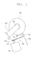
- the traverse device 70 is arranged in proximity to the cradle 23. As illustrated in FIG. 3 , the traverse device 70 includes a traverse drive motor 76, a swing-drive shaft 77, and a traverse arm 74.
- the traverse drive motor 76 is adapted to drive and swing the traverse arm 74 and is constituted of a servomotor or the like.
- An output shaft of the traverse drive motor 76 is the swing-drive shaft 77.
- the swing-drive shaft 77 is connected to a base-end portion of the traverse arm 74 in a longitudinal direction of the traverse arm 74.
- the traverse arm 74 is fixed to the swing-drive shaft 77 in a relatively non-rotatable manner.
- the longitudinal direction of the traverse arm 74 and the swing-drive shaft 77 are substantially perpendicular to each other.
- a traverse guide 73 is formed at a tip-end portion of the traverse arm 74 (an end portion opposite to the base-end portion in the longitudinal direction).
- the traverse guide 73 is formed into a shape by which the traverse guide 73 can be engaged with the yarn 20 to be wound around the winding bobbin 22 (a shape by which the traverse guide 73 can hook the yarn 20).
- the traverse guide 73 reciprocates with respect to a direction of a winding width of the package 30 (a left-right direction in FIG. 2 , a perpendicular direction in the plane of FIG. 3 ).
- a direction of a winding width of the package 30 a left-right direction in FIG. 2 , a perpendicular direction in the plane of FIG. 3 .
- the traverse arm 74 of the present embodiment includes an arm body 71, a guide member 75, and a mounting member, 72.
- the arm body 71 is formed into an elongated shape.
- a side where the swing-drive shaft 77 is mounted and a side opposite thereof (a side of the traverse guide 73) are respectively referred to as a "base-end” and a "tip-end".
- the longitudinal direction of the arm body 71 may be simply referred to as a "longitudinal direction”.
- a direction parallel to an axial line of the swing-drive shaft 77 is referred to as a "swing-drive shaft direction”.
- the swing-drive shaft direction is perpendicular to the longitudinal direction of the arm body 71.
- a direction perpendicular to the longitudinal direction and the swing-drive shaft direction (a left-right direction in FIG. 4B ) is referred to as a "traverse width direction”.
- the arm body 71 is made of a processed plate member. Since the arm body 71 is made of the plate member, configuration of the thin arm body 71 is possible, thereby allowing reduction in weight of the arm body 71.
- the arm body 71 of the present embodiment is made of a pressed aluminum plate. Since the arm body 71 is made of the aluminum plate, the configuration of the thin arm body 71 is possible and appropriate stiffness can be ensured. Since the arm body 71 is made by a press machine, the arm body 71 is easily produced in a large quantity.
- the traverse guide 73 is formed at the tip-end portion of the arm body 71. As described above, the traverse guide 73 is formed into the shape by which the traverse guide 73 can be engaged with the yarn 20. The traverse guide 73 of the present embodiment is formed into a hook shape as illustrated in FIG. 4B .
- the guide member 75 is arranged in a portion of the traverse guide 73 where the traverse guide 73 makes contact with the yarn 20 (in the present embodiment, an inner portion of the hook-shaped traverse guide 73).
- the guide member 75 is made of a material superior in abrasion resistance such as ceramics, and is fixed to the arm body 71. The yarn 20 to be traversed by the traverse device 70 travels while making contact with the guide member 75.
- the traverse arm 74 When the traverse arm 74 is driven and swung, a large amount of torque is applied between the traverse arm 74 and the swing-drive shaft 77. A portion of the traverse arm 74 to which the swing-drive shaft 77 is mounted thus requires adequate stiffness. Since the arm body 71 of the present embodiment is made of the aluminum plate, it is difficult to provide a base-end portion of the arm body 71 with stiffness that allows the swing-drive shaft 77 to be directly attached thereto.
- the mounting member 72 for mounting the swing-drive shaft 77 is arranged at the base-end portion of the traverse arm 74 of the present embodiment.
- a mounting hole 78 for mounting the swing-drive shaft 77 is formed in the mounting member 72.
- a key groove 79 for preventing the traverse arm 74 from relatively rotating with respect to the swing-drive shaft 77 is formed in the mounting hole 78.
- the mounting member 72 is provided separately from the arm body 71. Since the mounting member 72 is provided separately from the arm body 71, the mounting member 72 can be formed by a manufacturing method (e.g., using a cutting machine) other than using the press machine. The mounting member 72 thus can be formed into any shape that ensures adequate stiffness. In the present embodiment, the mounting member 72 is made of aluminum.
- the hook-shaped traverse guide 73 is formed at the tip end of the arm body 71.
- a flat-plate portion 80 for fixing the mounting member 72 is formed at the base end of the arm body 71.
- a portion of the arm body 71 between the traverse guide 73 and the flat-plate portion 80 is referred to as an intermediate portion 85.
- the traverse guide 73, the intermediate portion 85 and the flat-plate portion 80 are formed by processing one piece of aluminum plate by the press machine.
- the traverse guide 73, the intermediate portion 85, and the flat-plate portion are formed as one body.
- the flat-plate portion 80 is formed as a flat plate perpendicular to the swing-drive shaft 77. Since the flat-plate portion 80 is formed as the flat plate perpendicular to the swing-drive shaft 77, the mounting member 72 can be stably mounted to the flat-plate portion 80.
- the arm body 71 is bent in a boundary portion between the traverse guide 73 and the intermediate portion 85 when viewed in the traverse width direction.
- the arm body 71 is bent in such a manner for positioning the traverse guide 73 to be closer to an outer periphery of the contact roller 29 as illustrated in FIG. 3 .
- the bending in the boundary portion between the traverse guide 73 and the intermediate portion 85 can be formed using the press machine.
- a contour shape of the intermediate portion 85 of the arm body 71 is formed so as to become gradually thicker from the tip-end portion towards the base-end portion when viewed in the swing-drive shaft direction. This causes stiffness in a portion of the arm body 71 to be higher as the portion is located close to the base-end portion within a plane perpendicular to the swing-drive shaft 77 (within a plane illustrated in FIG. 5 ). Therefore, e.g., even if the yarn 20 is caught in the traverse guide 73 and thereby causes force on the traverse arm 74, the arm body 71 is not likely to change its shape within the plane perpendicular to the swing-drive shaft 77.
- a protrusion 82 that protrudes towards one side in the swing-drive shaft direction within a cross section perpendicular to the longitudinal direction (within a cross section illustrated in FIG. 7 ) is formed in the intermediating portion 85 of the arm body 71 of the present embodiment.
- a recess that recesses towards one side in the swing-drive shaft direction is formed. Since the protrusion and the recess are inextricably linked together, the relevant portion will be described as the protrusion 82 in the following description.
- the protrusion 82 is formed by drawing or bending by the press machine. Forming the protrusion 82 in the arm body 71 allows enhancement in the stiffness of the arm body 71 within a plane including the swing-drive shaft direction and the longitudinal direction (within a plane illustrated in FIG. 6 ).
- the protrusion 82 is formed such that a protrusion amount of the protrusion 82 gradually becomes larger from the tip-end portion towards the base-end portion. This causes the stiffness in a portion of the arm body 71 to be higher as the portion is located close to the base-end portion within the plane including the swing-drive shaft direction and the longitudinal direction (within the plane illustrated in FIG. 6 ).
- the protrusion 82 of the arm body 71 is formed such that a protrusion amount of the protrusion 82 in the same direction as the swing-drive shaft 77 is larger at a portion of the arm body 71 (e.g. the base-end portion) located away from the tip-end portion in the longitudinal direction than at a portion of the arm body 71 located close to the tip-end portion in the longitudinal direction.
- the arm body 71 is not likely to change its shape within the plane including the swing-drive shaft direction and the longitudinal direction (within the plane illustrated in FIG. 6 ).
- the protrusion 82 is formed by bending the plate member (an aluminum plate in the present embodiment) of the arm body 71 within the cross section perpendicular to the longitudinal direction.
- the protrusion 82 is formed by the aluminum plate being bent in a polygonal line within the cross section perpendicular to the longitudinal direction.
- the protrusion 82 is formed by connecting planes to one another, each plane facing in a different direction.
- the arm body 71 includes a front portion 83 and a side portion 84.
- each of the front portion 83 and the side portion 84 is formed as a triangular plane of which the width widens from the tip-end portion towards the base-end portion.
- the front portion 83 is formed such that a normal line of the front portion 83 is in the swing-drive shaft direction (that is, the front portion 83 faces in the swing-drive shaft direction).
- the side portion 84 is connected to each of both end portions of the front portion 83 in the traverse width direction. As illustrated in FIG. 7 , the side portion 84 is connected diagonally with respect to the front portion 83 within the cross section perpendicular to the longitudinal direction. Therefore, a normal line of the side portion 84 faces in a direction diagonal with respect to the swing-drive shaft direction.
- the front portion 83 and the side portion 84 are connected to each other at an obtuse angle within the cross section perpendicular to the longitudinal direction.
- the aluminum plate of the arm body 71 is bent at an obtuse angle within the cross section. Since an angle at which the aluminum plate is bent is obtuse, the protrusion 82 is easily formed by bending the aluminum plate by the press machine.
- the arm body 71 of the present embodiment includes a planar bottom portion 86 for connecting a side of the front portion 83 on a base-end portion side to the flat-plate portion 80.
- the bottom portion 86 is formed into a trapezoidal shape and is connected to each side of the front portion 83 and the side portion 84 on the base-end portion side.
- the flat-plate portion 80 and the front portion 83 are arranged substantially parallel to each other.
- a step 87 is formed between the front portion 83 and the flat-plate portion 80 in the swing-drive shaft direction.
- a structure for mounting the mounting member 72 to the arm body 71 will be described in detail.
- a through hole 81 for inserting a screw is formed through the flat-plate portion 80.
- the mounting member 72 can be fixed to the flat-plate portion 80.
- a forming method of the through hole 81 is not particularly limited.
- the through hole 81 is formed by punching out the plate member using the press machine. This allows simultaneous formation of the through hole 81 when forming the arm body 71 by the press machine.
- two through holes 81 are formed side by side in the traverse width direction.
- screws are threaded into each of the two through holes 81 and are screwed into the mounting member 72.
- the mounting member 72 By screwing the mounting member 72 via a plurality of the through holes formed through the arm body 71, the mounting member 72 can be stably fixed to the arm body 71.
- a trough hole 88 is also formed at the base end of the protrusion 82 (specifically, at a base end of the front portion 83).
- the mounting member 72 is arranged over the protrusion 82 and the flat-plate portion 80.
- a screw is threaded into the through hole 88 formed through the protrusion 82 and is screwed into the mounting member 72. Accordingly, since the mounting member 72 can be fixed to both of the protrusion 82 and the flat-plate portion 80, the mounting member 72 can be stably fixed to the arm body 71.
- the through hole 88 formed through the protrusion 82 and the two through holes 81 formed through the flat-plate portion 80 constitute vertices of a triangle when viewed in the swing-drive shaft direction.
- the mounting member 72 of the present embodiment is screwed to the arm body 71 at three points when viewed in the swing-drive shaft direction. Accordingly, the mounting member 72 can be more stably fixed to the arm body 71 within the plane perpendicular to the swing-drive shaft direction (within the plane illustrated in FIG. 5 ).
- the traverse arm 74 of the present embodiment includes the arm body 71 and the traverse guide 73 arranged at the tip-end portion of the arm body 71 in the longitudinal direction, and is driven and swung about the swing-drive shaft 77 arranged substantially perpendicular to the longitudinal direction of the arm body 71.
- the arm body 71 is made of the plate member, and a portion of the plate member is bent within the cross section perpendicular to the longitudinal direction (within the cross section illustrated in FIG. 7 ) to form the protrusion 82 that protrudes in the swing-drive shaft direction.
- the arm body 71 is made of the plate member, the configuration of the thin arm body 71 is possible, thereby allowing reduction in the weight of arm body 71.
- Forming the protrusion 82 in the arm body 71 by bending the plate member within the plane perpendicular to the longitudinal direction ensures the stiffness of the arm body 71 in a simple configuration.
- a press machine or the like can be used for bending the plate member, thereby allowing facilitation of manufacture.
- the protrusion 82 of the arm body 71 is formed such that the protrusion amount of the protrusion 82 is larger at a portion located away from the tip-end portion in the longitudinal direction than at the tip-end portion.
- the stiffness of the traverse arm 74 can be gradually enhanced in a direction away from the tip-end portion.
- the aluminum plate of the arm body 71 is bent in a polygonal line at an obtuse angle within the plane perpendicular to the longitudinal direction.
- the aluminum plate is bent at an obtuse angle to form the protrusion 82.
- the plate member can be easily bent by the press machine or the like.
- the traverse arm 74 of the present embodiment includes the mounting member 72.
- the mounting member 72 is provided separately from the arm body 71, and is mounted to the swing-drive shaft 77.
- the mounting member 72 is fixed to the base-end portion of the arm body 71 in the longitudinal direction.
- the base-end portion of the traverse arm 74 especially requires stiffness.
- the arm body 71 includes at the base-end portion in the longitudinal direction, the flat-plate portion 80 substantially perpendicular to the swing-drive shaft 77.
- the mounting member 72 is fixed to the flat-plate portion 80.
- the mounting member 72 can be stably fixed to the base-end portion of the arm body 71.
- the mounting member 72 is arranged over the flat-plate portion 80 and the protrusion 82, and is fixed to each of the flat-plate portion 80 and the protrusion 82.
- the mounting member 72 By arranging the mounting member 72 over the protrusion 82 and the flat-plate portion 80, the mounting member 72 can be more stably fixed to the arm body 71.
- the through holes 81 and 88 are formed through the arm body 71 so as to pass through screws.
- the mounting member 72 is fixed to the arm body 71 by fastening the screws via the through holes 81 and 88.
- the arm body 71 and the mounting member 72 can be firmly fastened to each other.
- the through holes 81 and 88 for passing through the screws can be formed through the arm body 71 by the press machine or the like.
- the automatic winder 1 of the present embodiment includes the plurality of winder units 10.
- Each of the winder units 10 includes the traverse device 70 adapted to traverse the yarn 20 by the traverse arm 74.
- the automatic winder 1 includes the light traverse arm 74 superior in stiffness property and manufacturable at low cost, the yarn 20 to be wound can be stably traversed, and in addition, costs can be reduced.
- the package 30 having high quality can be formed at low cost.
- the arm body 71 is formed by pressing an aluminum plate, without limited thereto, the arm body 71 may be made of an appropriate metal plate. As a material for the arm body 71, a light material having adequate stiffness property is preferable.
- the material for the arm body 71 is not limited to a metal plate, and the arm body 71 may be formed by appropriately bending another plate member.
- An arm body of which shape is equivalent to the arm body 71 of the above-described embodiment can be formed with a material such as a CFRP (Carbon Fiber Reinforced Plastics) plate.
- a hole for reducing weight may be appropriately formed through the arm body 71.
- the arm body 71 is bent in a polygonal line within the plane perpendicular to the longitudinal direction to form the protrusion 82.
- the protrusion 82 has a polyhedral shape.
- the protrusion 82 may be formed by, e.g., bending the arm body 71 in a curved line within the plane perpendicular to the longitudinal direction. In this case, the protrusion 82 is curved. The point is that the protrusion 82 (or the recess) merely requires to be formed by bending the arm body 71 within the plane perpendicular to the longitudinal direction, and its shape is not particularly limited.
- At least one protrusion is required to be formed in the arm body 71, and a plurality of the protrusions may be formed.
- the material of the mounting member 72 is aluminum.
- the material of the mounting member 72 is not limited to the aluminum, and is merely required to have a certain degree of stiffness.
- the material of the mounting member 72 and the material of the arm body 71 may be different.
- the structure for mounting the mounting member 72 to the arm body 71 is not limited to the above-described structure, and an appropriate structure may be employed.
- the mounting member 72 may be omitted and the arm body 71 may be directly mounted to the swing-drive shaft 77.
- the fixing member for fixing the mounting member 72 to the arm body 71 is not limited to a screw, and may be, e.g., a caulking pin.
Landscapes
- Guides For Winding Or Rewinding, Or Guides For Filamentary Materials (AREA)
- Winding Filamentary Materials (AREA)
Abstract
Description
- The present invention relates to a traverse arm for traversing a yarn in a yarn winding machine.
- The yarn winding machine includes a traverse device for traversing a yarn to be wound around a winding bobbin. As such a traverse device, there is conventionally known an arm-type traverse device including a traverse arm adapted to be driven and swung. Such a traverse device is described in Japanese Unexamined Patent Application Publication No.
2011-195217 2010-137944 - Since the traverse arm is driven and swung at a high speed, the traverse arm preferably has an utmost possible lightweight property. On the other hand, the traverse arm requires strength such that in a where force from a caught yarn or the like is applied, the traverse arm is not broken or bent.
- In this respect. Patent Document 2 discloses a traverse arm having a truss structure in which a beam is sandwiched between two plates. According to Patent Document 2, employing the truss structure in the traverse arm allows reducing weight of the traverse arm and enhancing stiffness thereof.
- The object of the present invention is to provide a light traverse arm superior in strength property and manufacturable at low cost, and a yarn winding machine including same.
This object is achieved by a traverse arm according to claim 1, and by a yarn winding machine according to claim 9. - The traverse arm having the truss structure disclosed in Patent Document 2 has a complicated structure in which the two plates and the beam are pasted together. Therefore, there is a problem in which manufacturing cost is high, and manufacturing is difficult.
- According to an aspect of the present invention, a traverse arm includes an arm body and a traverse guide arranged at a tip-end portion of the arm body in a longitudinal direction of the arm body, and is driven and swung about a swing-drive shaft arranged substantially perpendicular to the longitudinal direction of the arm body. The arm body is made of a plate member, and at least a portion of the plate member is bent within a cross section perpendicular to the longitudinal direction to form a protrusion that protrudes in a same direction as the swing-drive shaft.
- Since the arm body is made of the plate member, a configuration of a thin arm body is possible, thereby allowing reduction in weight of the arm body. Forming the protrusion in the arm body by bending the plate member within a plane perpendicular to the longitudinal direction ensures stiffness of the arm body in a simple configuration. For bending the plate member, a press machine can be used, e.g., thereby allowing facilitation of manufacture.
- It is preferable that in the traverse arm, the protrusion of the arm body is formed such that a protrusion amount of the protrusion in the same direction as the swing-drive shaft is larger at a portion located away from the tip-end portion in the longitudinal direction than at the tip-end portion.
- More stiffness is required in a portion of the traverse arm as the portion is located away from the tip-end portion. By forming the traverse arm in an above-described manner, the stiffness of the traverse arm is enhanced at the portion located away from the tip-end portion.
- In the traverse arm, it is preferable that the protrusion is formed by the plate member being bent in a polygonal line at an obtuse angle.
- The plate member is bent at an obtuse angle to form the protrusion. In comparison with a case of bending the plate member at a right angle, e.g., the plate member can be easily bent by the press machine or the like.
- The traverse arm preferably includes a mounting member. The mounting member is provided separately from the arm body, and the mounting member to be mounted to the swing-drive shaft is fixed to a base-end portion of the arm body in the longitudinal direction of the arm body.
- Since torque for driving and swinging the traverse arm is applied on a base-end portion of the traverse arm, the base-end portion of the traverse arm especially requires stiffness. Thus, by fixing the mounting member having adequate stiffness to the base-end portion of the arm body in the above-described manner, the stiffness at the base-end portion of the traverse arm can be ensured.
- The arm body of the traverse arm includes at the base-end portion in the longitudinal direction, a flat-plate portion substantially perpendicular to the swing-drive shaft. The mounting member is fixed to at least the flat-plate portion.
- Since the flat-plate portion is arranged at the base-end portion of the arm body and the mounting member is mounted to the flat-plate portion, the mounting member can be stably fixed to the base-end portion of the arm body.
- In the traverse arm, it is preferable that the mounting member is arranged over the flat-plate portion and the protrusion, and is fixed to each of the flat-plate portion and the protrusion.
- By arranging the mounting member over the protrusion and the flat-plate portion, the mounting member can be more stably fixed to the arm body.
- In the traverse arm, a through hole is preferably formed through the arm body so as to receive a fixing member. The mounting member is fixed to the arm body by the fixing member.
- By mounting the fixing member to the mounting member via the through hole formed through the arm body, the arm body and the mounting body can be firmly fastened to each other. The through hole for passing through the fixing member can be formed through the arm body by the press machine or the like.
- According to another aspect of the present invention, a yarn winding machine includes a plurality of winding units. Each of the winding units includes a traverse device adapted to traverse a yarn by the above-described traverse arm.
- Since the yarn winding machine includes the traverse arm of the present invention, which is light, superior in stiffness property, and manufacturable at low cost, the yarn to be wound can be stably traversed, and in addition, costs can be reduced. Thus, according to the yarn winding machine of the present invention, a package having high quality can be formed at low cost.
-
-
FIG. 1 is a front view of an automatic winder according to one embodiment of the present invention; -
FIG. 2 is a schematic front view of a winder unit; -
FIG. 3 is a side view illustrating proximity of a traverse device; -
FIG. 4A is a side view of a traverse arm; -
FIG. 4B is a front view of the traverse arm; -
FIG. 4C is a perspective view of the traverse arm; -
FIG. 5 is a front view of an arm body; -
FIG. 6 is a cross sectional view taken along arrows A-A ofFIG. 5 ; and -
FIG. 7 is a cross sectional view taken along arrows B-B ofFIG. 5 , and a cross sectional view taken along arrows C-C ofFIG. 5 . - Next, an embodiment of the present invention will be described. Firstly, a configuration of an automatic winder (yarn winding machine) 1 of the present embodiment will be described with reference to
FIGS. 1 to 3 . "Upstream" and "downstream" in the present specification respectively indicate upstream and downstream in a travelling direction of a yarn at the time of yarn winding. - As illustrated in
FIG. 1 , the automatic winder (yarn winding machine) 1 includes a plurality of winder units (winding units) 10 arranged next to each other. - As illustrated in
FIG. 2 , each of thewinder units 10 includes ayarn supplying section 11, a yarn unwinding assisting device 12, atension applying device 13, a splicer device (yarn joining device) 14, a clearer (yarn defect detecting device) 15, and awinding section 16. Thewinder unit 10 includes aunit control section 50 adapted to control an operation of each of the sections provided in thewinder unit 10. - The
yarn supplying section 11 holds in a predetermined position, theyarn supplying bobbin 21 adapted to supply ayarn 20. - The yarn unwinding assisting device 12 includes a regulating
member 40 covering a core tube of theyarn supplying bobbin 21. The regulatingmember 40 makes contact with a portion (balloon), which is swung around theyarn supplying bobbin 21 by centrifugal force, of theyarn 20 having been unwound from theyarn supplying bobbin 21. In this manner, the yarn unwinding assisting device 12 controls the balloon such that a size of the balloon is appropriate, and assists unwinding of theyarn 20 from theyarn supplying bobbin 21. - The
tension applying device 13 applies a predetermined tension on the travellingyarn 20. Thetension applying device 13 may be, e.g., a gate type in which movable comb teeth are arranged with respect to fixed comb teeth. Since theyarn 20 bends and passes through between the engaged comb teeth, resistance is applied on the travellingyarn 20 and thereby allowing an appropriate tension to be applied on theyarn 20. Other than the gate type, a disc type, e.g., may be employed as thetension applying device 13. - The clearer 15 includes a sensor, which is not illustrated, for detecting an abnormal portion of the yarn 20 (yarn defect). Provided in proximity to the clearer 15 is a
cutter 39 for immediately cutting theyarn 20 when the clearer 15 detects the yarn defect. - The
splicer device 14 joins a lower yarn from theyarn supplying bobbin 21 and an upper yarn from a windingbobbin 22 at the time of a yarn cutting performed after the clearer 15 detects the yarn defect, a yarn breakage during the unwinding from theyarn supplying bobbin 21, or the like. A yarn joining device adapted to perform yarn joining of the upper yarn and the lower yarn in such a manner may be a mechanical type, a type of using fluid such as compressed air, or the like. - A lower
yarn catching member 25 for catching a yarn end from theyarn supplying bobbin 21 and guiding the yarn end to thesplicer device 14 is arranged in a part below thesplicer device 14. An upperyarn catching member 26 for catching a yarn end from the windingbobbin 22 and guiding the yarn end to thesplicer device 14 is arranged in a part above thesplicer device 14. - The winding
section 16 includes acradle 23 adapted to support the windingbobbin 22 for winding theyarn 20, and acontact roller 29 capable of rotating by being in contact with a peripheral surface of the windingbobbin 22. The windingsection 16 includes a rotary drive source, which is not illustrated, for driving and rotating the windingbobbin 22 supported by thecradle 23. By driving and rotating the windingbobbin 22, theyarn 20 can be wound around an outer periphery of the windingbobbin 22. The windingbobbin 22 around which theyarn 20 is wound is referred to as apackage 30. - The
winder unit 10 includes an armtype traverse device 70 adapted to traverse theyarn 20 to be wound around the windingbobbin 22. Thetraverse device 70 is arranged in proximity to thecradle 23. As illustrated inFIG. 3 , thetraverse device 70 includes atraverse drive motor 76, a swing-drive shaft 77, and atraverse arm 74. - The
traverse drive motor 76 is adapted to drive and swing thetraverse arm 74 and is constituted of a servomotor or the like. An output shaft of thetraverse drive motor 76 is the swing-drive shaft 77. As illustrated inFIG. 3 , the swing-drive shaft 77 is connected to a base-end portion of thetraverse arm 74 in a longitudinal direction of thetraverse arm 74. Thetraverse arm 74 is fixed to the swing-drive shaft 77 in a relatively non-rotatable manner. As illustrated inFIG. 3 , in a state where thetraverse arm 74 is fixed to the swing-drive shaft 77, the longitudinal direction of thetraverse arm 74 and the swing-drive shaft 77 are substantially perpendicular to each other. - A
traverse guide 73 is formed at a tip-end portion of the traverse arm 74 (an end portion opposite to the base-end portion in the longitudinal direction). Thetraverse guide 73 is formed into a shape by which thetraverse guide 73 can be engaged with theyarn 20 to be wound around the winding bobbin 22 (a shape by which thetraverse guide 73 can hook the yarn 20). - Since a rotor of the
traverse drive motor 76 repeats forward/reverse rotations and thereby swings thetraverse arm 74, thetraverse guide 73 reciprocates with respect to a direction of a winding width of the package 30 (a left-right direction inFIG. 2 , a perpendicular direction in the plane ofFIG. 3 ). By rotating the windingbobbin 22 in a state where thetraverse guide 73 is engaged with theyarn 20, theyarn 20 is wound around the windingbobbin 22 while being traversed, thereby a predetermined-shapedpackage 30 can be formed. - Next, the
traverse arm 74 according to the present embodiment will be described with reference toFIGS. 4A to 4C . - As illustrated in
FIGS. 4A to 4C , thetraverse arm 74 of the present embodiment includes anarm body 71, aguide member 75, and a mounting member, 72. - As illustrated in
FIGS. 4A to 4C , thearm body 71 is formed into an elongated shape. In a longitudinal direction of thearm body 71, a side where the swing-drive shaft 77 is mounted and a side opposite thereof (a side of the traverse guide 73) are respectively referred to as a "base-end" and a "tip-end". In the following description, the longitudinal direction of thearm body 71 may be simply referred to as a "longitudinal direction". Furthermore, in the following description, a direction parallel to an axial line of the swing-drive shaft 77 is referred to as a "swing-drive shaft direction". The swing-drive shaft direction is perpendicular to the longitudinal direction of thearm body 71. A direction perpendicular to the longitudinal direction and the swing-drive shaft direction (a left-right direction inFIG. 4B ) is referred to as a "traverse width direction". - The
arm body 71 is made of a processed plate member. Since thearm body 71 is made of the plate member, configuration of thethin arm body 71 is possible, thereby allowing reduction in weight of thearm body 71. - Specifically, the
arm body 71 of the present embodiment is made of a pressed aluminum plate. Since thearm body 71 is made of the aluminum plate, the configuration of thethin arm body 71 is possible and appropriate stiffness can be ensured. Since thearm body 71 is made by a press machine, thearm body 71 is easily produced in a large quantity. - As illustrated in
FIGS. 4A to 4C , thetraverse guide 73 is formed at the tip-end portion of thearm body 71. As described above, thetraverse guide 73 is formed into the shape by which thetraverse guide 73 can be engaged with theyarn 20. Thetraverse guide 73 of the present embodiment is formed into a hook shape as illustrated inFIG. 4B . - The
guide member 75 is arranged in a portion of thetraverse guide 73 where thetraverse guide 73 makes contact with the yarn 20 (in the present embodiment, an inner portion of the hook-shaped traverse guide 73). Theguide member 75 is made of a material superior in abrasion resistance such as ceramics, and is fixed to thearm body 71. Theyarn 20 to be traversed by thetraverse device 70 travels while making contact with theguide member 75. - When the
traverse arm 74 is driven and swung, a large amount of torque is applied between thetraverse arm 74 and the swing-drive shaft 77. A portion of thetraverse arm 74 to which the swing-drive shaft 77 is mounted thus requires adequate stiffness. Since thearm body 71 of the present embodiment is made of the aluminum plate, it is difficult to provide a base-end portion of thearm body 71 with stiffness that allows the swing-drive shaft 77 to be directly attached thereto. - The mounting
member 72 for mounting the swing-drive shaft 77 is arranged at the base-end portion of thetraverse arm 74 of the present embodiment. A mountinghole 78 for mounting the swing-drive shaft 77 is formed in the mountingmember 72. Akey groove 79 for preventing thetraverse arm 74 from relatively rotating with respect to the swing-drive shaft 77 is formed in the mountinghole 78. - In the
traverse arm 74 of the present embodiment, the mountingmember 72 is provided separately from thearm body 71. Since the mountingmember 72 is provided separately from thearm body 71, the mountingmember 72 can be formed by a manufacturing method (e.g., using a cutting machine) other than using the press machine. The mountingmember 72 thus can be formed into any shape that ensures adequate stiffness. In the present embodiment, the mountingmember 72 is made of aluminum. - Next, a configuration of the
arm body 71 will be described in detail with reference toFIGS. 5 to 7 . - As described above, the hook-shaped
traverse guide 73 is formed at the tip end of thearm body 71. As illustrated inFIG. 5 , a flat-plate portion 80 for fixing the mountingmember 72 is formed at the base end of thearm body 71. In the following description, a portion of thearm body 71 between thetraverse guide 73 and the flat-plate portion 80 is referred to as anintermediate portion 85. - In the
arm body 71 of the present embodiment, thetraverse guide 73, theintermediate portion 85 and the flat-plate portion 80 are formed by processing one piece of aluminum plate by the press machine. Thetraverse guide 73, theintermediate portion 85, and the flat-plate portion are formed as one body. - As illustrated in
FIG. 6 , the flat-plate portion 80 is formed as a flat plate perpendicular to the swing-drive shaft 77. Since the flat-plate portion 80 is formed as the flat plate perpendicular to the swing-drive shaft 77, the mountingmember 72 can be stably mounted to the flat-plate portion 80. - As illustrated in
FIG. 6 , thearm body 71 is bent in a boundary portion between thetraverse guide 73 and theintermediate portion 85 when viewed in the traverse width direction. Thearm body 71 is bent in such a manner for positioning thetraverse guide 73 to be closer to an outer periphery of thecontact roller 29 as illustrated inFIG. 3 . The bending in the boundary portion between thetraverse guide 73 and theintermediate portion 85 can be formed using the press machine. - As illustrated in
FIG. 5 , a contour shape of theintermediate portion 85 of thearm body 71 is formed so as to become gradually thicker from the tip-end portion towards the base-end portion when viewed in the swing-drive shaft direction. This causes stiffness in a portion of thearm body 71 to be higher as the portion is located close to the base-end portion within a plane perpendicular to the swing-drive shaft 77 (within a plane illustrated inFIG. 5 ). Therefore, e.g., even if theyarn 20 is caught in thetraverse guide 73 and thereby causes force on thetraverse arm 74, thearm body 71 is not likely to change its shape within the plane perpendicular to the swing-drive shaft 77. - As illustrated in
FIG. 7 , aprotrusion 82 that protrudes towards one side in the swing-drive shaft direction within a cross section perpendicular to the longitudinal direction (within a cross section illustrated inFIG. 7 ) is formed in the intermediatingportion 85 of thearm body 71 of the present embodiment. When viewing theprotrusion 82 from the back, it can be said that a recess that recesses towards one side in the swing-drive shaft direction is formed. Since the protrusion and the recess are inextricably linked together, the relevant portion will be described as theprotrusion 82 in the following description. - For example, the
protrusion 82 is formed by drawing or bending by the press machine. Forming theprotrusion 82 in thearm body 71 allows enhancement in the stiffness of thearm body 71 within a plane including the swing-drive shaft direction and the longitudinal direction (within a plane illustrated inFIG. 6 ). - As illustrated in cross sectional views of
FIG. 6 and FIG. 7 , theprotrusion 82 is formed such that a protrusion amount of theprotrusion 82 gradually becomes larger from the tip-end portion towards the base-end portion. This causes the stiffness in a portion of thearm body 71 to be higher as the portion is located close to the base-end portion within the plane including the swing-drive shaft direction and the longitudinal direction (within the plane illustrated inFIG. 6 ). In other words, theprotrusion 82 of thearm body 71 is formed such that a protrusion amount of theprotrusion 82 in the same direction as the swing-drive shaft 77 is larger at a portion of the arm body 71 (e.g. the base-end portion) located away from the tip-end portion in the longitudinal direction than at a portion of thearm body 71 located close to the tip-end portion in the longitudinal direction. - With the above-described configuration, e.g., even if the
yarn 20 is caught in thetraverse guide 73 and thereby causes force on thetraverse arm 74, thearm body 71 is not likely to change its shape within the plane including the swing-drive shaft direction and the longitudinal direction (within the plane illustrated inFIG. 6 ). - Next, a configuration of the
protrusion 82 will be described more specifically. - As illustrated in
FIG. 7 , theprotrusion 82 is formed by bending the plate member (an aluminum plate in the present embodiment) of thearm body 71 within the cross section perpendicular to the longitudinal direction. In the present embodiment, as illustrated inFIG. 7 , theprotrusion 82 is formed by the aluminum plate being bent in a polygonal line within the cross section perpendicular to the longitudinal direction. - As illustrated in a perspective view of
FIG. 4C and the like, theprotrusion 82 is formed by connecting planes to one another, each plane facing in a different direction. Specifically, as illustrated inFIG. 5 ,FIG. 7 , and the like, thearm body 71 includes afront portion 83 and aside portion 84. - As illustrated in
FIG. 5 andFIG. 4C , each of thefront portion 83 and theside portion 84 is formed as a triangular plane of which the width widens from the tip-end portion towards the base-end portion. - The
front portion 83 is formed such that a normal line of thefront portion 83 is in the swing-drive shaft direction (that is, thefront portion 83 faces in the swing-drive shaft direction). Theside portion 84 is connected to each of both end portions of thefront portion 83 in the traverse width direction. As illustrated inFIG. 7 , theside portion 84 is connected diagonally with respect to thefront portion 83 within the cross section perpendicular to the longitudinal direction. Therefore, a normal line of theside portion 84 faces in a direction diagonal with respect to the swing-drive shaft direction. - As illustrated in
FIG. 7 , thefront portion 83 and theside portion 84 are connected to each other at an obtuse angle within the cross section perpendicular to the longitudinal direction. The aluminum plate of thearm body 71 is bent at an obtuse angle within the cross section. Since an angle at which the aluminum plate is bent is obtuse, theprotrusion 82 is easily formed by bending the aluminum plate by the press machine. - As illustrated in
FIG. 5 andFIG. 6 , thearm body 71 of the present embodiment includes aplanar bottom portion 86 for connecting a side of thefront portion 83 on a base-end portion side to the flat-plate portion 80. As illustrated inFIG. 5 , thebottom portion 86 is formed into a trapezoidal shape and is connected to each side of thefront portion 83 and theside portion 84 on the base-end portion side. - As illustrated in
FIG. 6 , the flat-plate portion 80 and thefront portion 83 are arranged substantially parallel to each other. Astep 87 is formed between thefront portion 83 and the flat-plate portion 80 in the swing-drive shaft direction. - A structure for mounting the mounting
member 72 to thearm body 71 will be described in detail. - As illustrated in
FIG. 5 , a throughhole 81 for inserting a screw (fixing member) is formed through the flat-plate portion 80. By screwing a fixing screw into the mountingmember 72 via the throughhole 81, the mountingmember 72 can be fixed to the flat-plate portion 80. A forming method of the throughhole 81 is not particularly limited. In the present embodiment, the throughhole 81 is formed by punching out the plate member using the press machine. This allows simultaneous formation of the throughhole 81 when forming thearm body 71 by the press machine. - In the flat-
plate portion 80 of the present embodiment, two throughholes 81 are formed side by side in the traverse width direction. When fixing the mountingmember 72 to the flat-plate portion 80, screws are threaded into each of the two throughholes 81 and are screwed into the mountingmember 72. By screwing the mountingmember 72 via a plurality of the through holes formed through thearm body 71, the mountingmember 72 can be stably fixed to thearm body 71. - In the present embodiment, as illustrated in
FIG. 5 andFIG. 6 , atrough hole 88 is also formed at the base end of the protrusion 82 (specifically, at a base end of the front portion 83). As illustrated inFIGS. 4A to 4C , the mountingmember 72 is arranged over theprotrusion 82 and the flat-plate portion 80. When fixing the mountingmember 72 to thearm body 71, a screw is threaded into the throughhole 88 formed through theprotrusion 82 and is screwed into the mountingmember 72. Accordingly, since the mountingmember 72 can be fixed to both of theprotrusion 82 and the flat-plate portion 80, the mountingmember 72 can be stably fixed to thearm body 71. - Furthermore, in the present embodiment, as illustrated in
FIG. 5 , the throughhole 88 formed through theprotrusion 82 and the two throughholes 81 formed through the flat-plate portion 80 constitute vertices of a triangle when viewed in the swing-drive shaft direction. The mountingmember 72 of the present embodiment is screwed to thearm body 71 at three points when viewed in the swing-drive shaft direction. Accordingly, the mountingmember 72 can be more stably fixed to thearm body 71 within the plane perpendicular to the swing-drive shaft direction (within the plane illustrated inFIG. 5 ). - As described above, the
traverse arm 74 of the present embodiment includes thearm body 71 and thetraverse guide 73 arranged at the tip-end portion of thearm body 71 in the longitudinal direction, and is driven and swung about the swing-drive shaft 77 arranged substantially perpendicular to the longitudinal direction of thearm body 71. Thearm body 71 is made of the plate member, and a portion of the plate member is bent within the cross section perpendicular to the longitudinal direction (within the cross section illustrated inFIG. 7 ) to form theprotrusion 82 that protrudes in the swing-drive shaft direction. - Since the
arm body 71 is made of the plate member, the configuration of thethin arm body 71 is possible, thereby allowing reduction in the weight ofarm body 71. Forming theprotrusion 82 in thearm body 71 by bending the plate member within the plane perpendicular to the longitudinal direction ensures the stiffness of thearm body 71 in a simple configuration. A press machine or the like can be used for bending the plate member, thereby allowing facilitation of manufacture. - In the
traverse arm 74 of the present embodiment, theprotrusion 82 of thearm body 71 is formed such that the protrusion amount of theprotrusion 82 is larger at a portion located away from the tip-end portion in the longitudinal direction than at the tip-end portion. - Since more stiffness is required in a portion of the
traverse arm 74 as the portion is located away from the tip-end portion, by forming in the above-described manner, the stiffness of thetraverse arm 74 can be gradually enhanced in a direction away from the tip-end portion. - In the
traverse arm 74 of the present embodiment, the aluminum plate of thearm body 71 is bent in a polygonal line at an obtuse angle within the plane perpendicular to the longitudinal direction. - The aluminum plate is bent at an obtuse angle to form the
protrusion 82. In comparison with a case in which the aluminum plate is bent at a right angle, the plate member can be easily bent by the press machine or the like. - The
traverse arm 74 of the present embodiment includes the mountingmember 72. The mountingmember 72 is provided separately from thearm body 71, and is mounted to the swing-drive shaft 77. The mountingmember 72 is fixed to the base-end portion of thearm body 71 in the longitudinal direction. - Since the torque for driving and swinging the
traverse arm 74 is applied on the base-end portion of thetraverse arm 74, the base-end portion of thetraverse arm 74 especially requires stiffness. By fixing the mountingmember 72 having adequate stiffness to the base-end portion of thearm body 71 in the above-described manner, stiffness at the base-end portion of thetraverse arm 74 can be ensured. - In the
traverse arm 74 of the present embodiment, thearm body 71 includes at the base-end portion in the longitudinal direction, the flat-plate portion 80 substantially perpendicular to the swing-drive shaft 77. The mountingmember 72 is fixed to the flat-plate portion 80. - Since the flat-
plate portion 80 is arranged at the base-end portion of thearm body 71 and the mountingmember 72 is mounted to the flat-plate portion 80, the mountingmember 72 can be stably fixed to the base-end portion of thearm body 71. - In the
traverse arm 74 of the present embodiment, the mountingmember 72 is arranged over the flat-plate portion 80 and theprotrusion 82, and is fixed to each of the flat-plate portion 80 and theprotrusion 82. - By arranging the mounting
member 72 over theprotrusion 82 and the flat-plate portion 80, the mountingmember 72 can be more stably fixed to thearm body 71. - In the
traverse arm 74 of the present embodiment, the throughholes arm body 71 so as to pass through screws. The mountingmember 72 is fixed to thearm body 71 by fastening the screws via the throughholes - By screwing the screws into the mounting
member 72 via the throughholes arm body 71, thearm body 71 and the mountingmember 72 can be firmly fastened to each other. The through holes 81 and 88 for passing through the screws can be formed through thearm body 71 by the press machine or the like. - The automatic winder 1 of the present embodiment includes the plurality of
winder units 10. Each of thewinder units 10 includes thetraverse device 70 adapted to traverse theyarn 20 by thetraverse arm 74. - Since the automatic winder 1 includes the
light traverse arm 74 superior in stiffness property and manufacturable at low cost, theyarn 20 to be wound can be stably traversed, and in addition, costs can be reduced. Thus, with the automatic winder 1 of the present embodiment, thepackage 30 having high quality can be formed at low cost. - Although a preferred embodiment of the present invention has been described, the configuration may be changed, e.g., as described below.
- Although the
arm body 71 is formed by pressing an aluminum plate, without limited thereto, thearm body 71 may be made of an appropriate metal plate. As a material for thearm body 71, a light material having adequate stiffness property is preferable. - The material for the
arm body 71 is not limited to a metal plate, and thearm body 71 may be formed by appropriately bending another plate member. An arm body of which shape is equivalent to thearm body 71 of the above-described embodiment can be formed with a material such as a CFRP (Carbon Fiber Reinforced Plastics) plate. - A hole for reducing weight may be appropriately formed through the
arm body 71. - In the above-described embodiment, the
arm body 71 is bent in a polygonal line within the plane perpendicular to the longitudinal direction to form theprotrusion 82. In this case, as illustrated in the perspective view ofFIG. 4C , theprotrusion 82 has a polyhedral shape. Without limited thereto, theprotrusion 82 may be formed by, e.g., bending thearm body 71 in a curved line within the plane perpendicular to the longitudinal direction. In this case, theprotrusion 82 is curved. The point is that the protrusion 82 (or the recess) merely requires to be formed by bending thearm body 71 within the plane perpendicular to the longitudinal direction, and its shape is not particularly limited. - At least one protrusion is required to be formed in the
arm body 71, and a plurality of the protrusions may be formed. - In the above-described embodiment, the material of the mounting
member 72 is aluminum. However, the material of the mountingmember 72 is not limited to the aluminum, and is merely required to have a certain degree of stiffness. The material of the mountingmember 72 and the material of thearm body 71 may be different. - The structure for mounting the mounting
member 72 to thearm body 71 is not limited to the above-described structure, and an appropriate structure may be employed. The mountingmember 72 may be omitted and thearm body 71 may be directly mounted to the swing-drive shaft 77. - The fixing member for fixing the mounting
member 72 to thearm body 71 is not limited to a screw, and may be, e.g., a caulking pin.
Claims (9)
- A traverse arm comprising;
an arm body (71); and
a traverse guide (73) arranged at a tip-end portion of the arm body (71) in a longitudinal direction of the arm body (71),
the traverse arm adapted to be driven and swung about a swing-drive shaft (77) arranged substantially perpendicular to the longitudinal direction of the arm body (71),
wherein the arm body (71) is made of a plate member, and at least a portion of the plate member is bent within a cross section perpendicular to the longitudinal direction to form a protrusion (82) that protrudes in a same direction as the swing-drive shaft (77). - The traverse arm according to claim 1, wherein the protrusion (82) of the arm body (71) is formed such that a protrusion amount of the protrusion (82) in the same direction as the swing-drive shaft (77) is larger at a portion of the arm body (71) located away from the tip-end portion in the longitudinal direction than at a portion of the arm body (71) located close to the tip-end portion in the longitudinal direction.
- The traverse arm according to claim 1 or claim 2, wherein the protrusion (82) is formed by the plate member being bent in a polygonal line at an obtuse angle.
- The traverse arm according to any one of claim 1 through claim 3, further comprising a mounting member (72) provided separately from the arm body (71) and adapted to be mounted to the swing-drive shaft (77),
wherein the mounting member (72) is fixed to a base-end portion of the arm body (71) in the longitudinal direction of the arm body (71). - The traverse arm according to claim 4, wherein the arm body (71) includes a flat-plate portion (80) at the base-end portion in the longitudinal direction, the flat-plate portion (80) being substantially perpendicular to the swing-drive shaft (77), and
the mounting member (72) is fixed to at least the flat-plate portion (80). - The traverse arm according to claim 5, wherein the mounting member (72) is arranged over the flat-plate portion (80) and the protrusion (82), and is fixed to each of the flat-plate portion (80) and the protrusion (82).
- The traverse arm according to claim 5 or claim 6, wherein a through hole (81) is formed through the arm body (71), the through hole (81) being adapted to receive a fixing member, and
the mounting member (72) is fixed to the arm body (71) by the fixing member. - The traverse arm according to any one of claim 1 through claim 7, wherein the arm body (71) is a pressed metal plate.
- A yarn winding machine comprising a plurality of winding units (10), each winding unit (10) including a traverse device (70) adapted to traverse a yarn (20) by a traverse arm (74) according to any one of claim 1 through claim 8.
Applications Claiming Priority (1)
| Application Number | Priority Date | Filing Date | Title |
|---|---|---|---|
| JP2012217672A JP2014069931A (en) | 2012-09-28 | 2012-09-28 | Traverse arm, and yarn winding machine including the same |
Publications (3)
| Publication Number | Publication Date |
|---|---|
| EP2712830A2 true EP2712830A2 (en) | 2014-04-02 |
| EP2712830A3 EP2712830A3 (en) | 2015-02-18 |
| EP2712830B1 EP2712830B1 (en) | 2017-07-26 |
Family
ID=49230606
Family Applications (1)
| Application Number | Title | Priority Date | Filing Date |
|---|---|---|---|
| EP13185553.8A Not-in-force EP2712830B1 (en) | 2012-09-28 | 2013-09-23 | Traverse arm and yarn winding machine including the same |
Country Status (3)
| Country | Link |
|---|---|
| EP (1) | EP2712830B1 (en) |
| JP (1) | JP2014069931A (en) |
| CN (2) | CN103708283B (en) |
Cited By (2)
| Publication number | Priority date | Publication date | Assignee | Title |
|---|---|---|---|---|
| CN107651489A (en) * | 2016-07-26 | 2018-02-02 | 索若德国两合股份有限公司 | Yarn lateral-movement device including motor driver and finger-like cable guiding device |
| CN112520501A (en) * | 2021-02-03 | 2021-03-19 | 苏州天沐乐纺织有限公司 | Extension arm on creel |
Families Citing this family (6)
| Publication number | Priority date | Publication date | Assignee | Title |
|---|---|---|---|---|
| JP2014069931A (en) * | 2012-09-28 | 2014-04-21 | Murata Mach Ltd | Traverse arm, and yarn winding machine including the same |
| JP2016037354A (en) | 2014-08-07 | 2016-03-22 | 村田機械株式会社 | Traverse arm and yarn winding machine |
| CN105565070B (en) * | 2014-10-14 | 2020-01-03 | 舍弗勒技术股份两合公司 | Yarn guide and yarn winding machine |
| JP2017065898A (en) * | 2015-09-30 | 2017-04-06 | 村田機械株式会社 | Thread guard member, yarn storage device, and yarn winding machine |
| CN109081175A (en) * | 2018-09-04 | 2018-12-25 | 青岛宏大纺织机械有限责任公司 | A kind of automatic winder and its control method of swing rod guide |
| JP7493391B2 (en) * | 2020-06-16 | 2024-05-31 | 三菱電機株式会社 | lighting equipment |
Citations (2)
| Publication number | Priority date | Publication date | Assignee | Title |
|---|---|---|---|---|
| JP2010137944A (en) | 2008-12-10 | 2010-06-24 | Murata Machinery Ltd | Traverse arm and yarn winding machine including the same |
| JP2011195217A (en) | 2010-03-17 | 2011-10-06 | Murata Machinery Ltd | Yarn winding machine |
Family Cites Families (7)
| Publication number | Priority date | Publication date | Assignee | Title |
|---|---|---|---|---|
| CH693337A5 (en) * | 1999-06-16 | 2003-06-13 | Rieter Ag Maschf | Reciprocating yarn guide arm has structured mounting and end yarn guide sections, with an intermediate carrier section, of a material which withstands the yarn draw forces and alternating speed changes |
| ITMI20021175A1 (en) * | 2002-05-30 | 2003-12-01 | Gianpaolo Sarzilla | LICCIO OR MESH FOR WEAVING FRAMES AND ITS LICCI FRAME WITH HIGH STRUCTURAL SIMPLICITY AND WITH REDUCED NOISE OF OPERATION |
| ITMI20061122A1 (en) * | 2006-06-09 | 2007-12-10 | Colombo Filippetti Spa | PROCEDURE FOR THE HANDLING OF A THREAD GUIDE ELEMENT IN ROCKERS AND ITS OPERATING DEVICE |
| DE102008053261A1 (en) * | 2008-10-25 | 2010-04-29 | Oerlikon Textile Gmbh & Co. Kg | thread guides |
| EP2479129B1 (en) * | 2011-01-25 | 2016-08-10 | Murata Machinery, Ltd. | Yarn winding machine |
| JP2012153476A (en) * | 2011-01-25 | 2012-08-16 | Murata Machinery Ltd | Yarn winding device |
| JP2014069931A (en) * | 2012-09-28 | 2014-04-21 | Murata Mach Ltd | Traverse arm, and yarn winding machine including the same |
-
2012
- 2012-09-28 JP JP2012217672A patent/JP2014069931A/en active Pending
-
2013
- 2013-09-23 EP EP13185553.8A patent/EP2712830B1/en not_active Not-in-force
- 2013-09-24 CN CN201310447243.5A patent/CN103708283B/en active Active
- 2013-09-24 CN CN201320598990.4U patent/CN203624700U/en not_active Withdrawn - After Issue
Patent Citations (2)
| Publication number | Priority date | Publication date | Assignee | Title |
|---|---|---|---|---|
| JP2010137944A (en) | 2008-12-10 | 2010-06-24 | Murata Machinery Ltd | Traverse arm and yarn winding machine including the same |
| JP2011195217A (en) | 2010-03-17 | 2011-10-06 | Murata Machinery Ltd | Yarn winding machine |
Cited By (3)
| Publication number | Priority date | Publication date | Assignee | Title |
|---|---|---|---|---|
| CN107651489A (en) * | 2016-07-26 | 2018-02-02 | 索若德国两合股份有限公司 | Yarn lateral-movement device including motor driver and finger-like cable guiding device |
| CN107651489B (en) * | 2016-07-26 | 2019-09-06 | 索若德国两合股份有限公司 | Yarn lateral-movement device including motor driver and finger-like cable guiding device |
| CN112520501A (en) * | 2021-02-03 | 2021-03-19 | 苏州天沐乐纺织有限公司 | Extension arm on creel |
Also Published As
| Publication number | Publication date |
|---|---|
| EP2712830B1 (en) | 2017-07-26 |
| CN103708283B (en) | 2018-05-22 |
| CN103708283A (en) | 2014-04-09 |
| EP2712830A3 (en) | 2015-02-18 |
| JP2014069931A (en) | 2014-04-21 |
| CN203624700U (en) | 2014-06-04 |
Similar Documents
| Publication | Publication Date | Title |
|---|---|---|
| EP2712830B1 (en) | Traverse arm and yarn winding machine including the same | |
| EP2570377A1 (en) | Traverse guide, winding unit, and winding machine | |
| JP2008302994A (en) | Reel winding device and reel winding method | |
| EP2570376B1 (en) | Cradle, winding unit, and yarn winding machine | |
| EP2196423B1 (en) | Traverse arm and yarn winding machine including the same | |
| CN102457038A (en) | Cable guide device of electro-dynamic-type engineering machinery | |
| CN113026161B (en) | Spindle tension control device and control method of pay-off tension thereof | |
| CN1906106B (en) | Yarn guide, fiber bundle traverse device and fiber bundle roll manufacturing device | |
| JP2001179150A (en) | Automatic wallpaper sizing machine | |
| JP5930301B2 (en) | Finger-shaped yarn guide | |
| JP2012032755A (en) | Method and device for dismantling optical fiber cable | |
| JP2017065871A (en) | Yarn tension applying member, gate type yarn tension applying device and automatic winder | |
| JP2010137945A (en) | Traverse guide and yarn winding machine having the same | |
| JP2016079023A (en) | Yarn winder | |
| EP2937303B1 (en) | Winding drum, winding device and yarn winding machine | |
| JP2018012146A (en) | Wire stretching method and wire stretching apparatus | |
| JP2012525986A (en) | Disposable sewing wire spool | |
| JPH09233775A (en) | Motor rotor manufacturing equipment | |
| KR20210059740A (en) | Winding machine | |
| JP2007331915A (en) | Tension device | |
| JP2015020887A (en) | Disentanglement auxiliary device and automatic winder | |
| EP2712831B1 (en) | Traverse drum, yarn winding device, and method of manufacturing traverse drum | |
| CN110282506B (en) | Wire winding and unwinding device and method | |
| CN210176182U (en) | Traverse arm, winding unit, and yarn winding machine | |
| JP2009091121A (en) | Tire cord supply method |
Legal Events
| Date | Code | Title | Description |
|---|---|---|---|
| PUAI | Public reference made under article 153(3) epc to a published international application that has entered the european phase |
Free format text: ORIGINAL CODE: 0009012 |
|
| AK | Designated contracting states |
Kind code of ref document: A2 Designated state(s): AL AT BE BG CH CY CZ DE DK EE ES FI FR GB GR HR HU IE IS IT LI LT LU LV MC MK MT NL NO PL PT RO RS SE SI SK SM TR |
|
| AX | Request for extension of the european patent |
Extension state: BA ME |
|
| PUAL | Search report despatched |
Free format text: ORIGINAL CODE: 0009013 |
|
| AK | Designated contracting states |
Kind code of ref document: A3 Designated state(s): AL AT BE BG CH CY CZ DE DK EE ES FI FR GB GR HR HU IE IS IT LI LT LU LV MC MK MT NL NO PL PT RO RS SE SI SK SM TR |
|
| AX | Request for extension of the european patent |
Extension state: BA ME |
|
| RIC1 | Information provided on ipc code assigned before grant |
Ipc: B65H 54/28 20060101AFI20150109BHEP |
|
| 17P | Request for examination filed |
Effective date: 20150729 |
|
| RBV | Designated contracting states (corrected) |
Designated state(s): AL AT BE BG CH CY CZ DE DK EE ES FI FR GB GR HR HU IE IS IT LI LT LU LV MC MK MT NL NO PL PT RO RS SE SI SK SM TR |
|
| GRAP | Despatch of communication of intention to grant a patent |
Free format text: ORIGINAL CODE: EPIDOSNIGR1 |
|
| INTG | Intention to grant announced |
Effective date: 20170103 |
|
| GRAS | Grant fee paid |
Free format text: ORIGINAL CODE: EPIDOSNIGR3 |
|
| GRAJ | Information related to disapproval of communication of intention to grant by the applicant or resumption of examination proceedings by the epo deleted |
Free format text: ORIGINAL CODE: EPIDOSDIGR1 |
|
| GRAL | Information related to payment of fee for publishing/printing deleted |
Free format text: ORIGINAL CODE: EPIDOSDIGR3 |
|
| GRAR | Information related to intention to grant a patent recorded |
Free format text: ORIGINAL CODE: EPIDOSNIGR71 |
|
| INTC | Intention to grant announced (deleted) | ||
| GRAA | (expected) grant |
Free format text: ORIGINAL CODE: 0009210 |
|
| INTG | Intention to grant announced |
Effective date: 20170612 |
|
| AK | Designated contracting states |
Kind code of ref document: B1 Designated state(s): AL AT BE BG CH CY CZ DE DK EE ES FI FR GB GR HR HU IE IS IT LI LT LU LV MC MK MT NL NO PL PT RO RS SE SI SK SM TR |
|
| REG | Reference to a national code |
Ref country code: GB Ref legal event code: FG4D |
|
| REG | Reference to a national code |
Ref country code: CH Ref legal event code: EP |
|
| REG | Reference to a national code |
Ref country code: AT Ref legal event code: REF Ref document number: 912169 Country of ref document: AT Kind code of ref document: T Effective date: 20170815 |
|
| REG | Reference to a national code |
Ref country code: IE Ref legal event code: FG4D |
|
| REG | Reference to a national code |
Ref country code: DE Ref legal event code: R096 Ref document number: 602013023963 Country of ref document: DE |
|
| REG | Reference to a national code |
Ref country code: NL Ref legal event code: MP Effective date: 20170726 |
|
| REG | Reference to a national code |
Ref country code: LT Ref legal event code: MG4D |
|
| REG | Reference to a national code |
Ref country code: AT Ref legal event code: MK05 Ref document number: 912169 Country of ref document: AT Kind code of ref document: T Effective date: 20170726 |
|
| PG25 | Lapsed in a contracting state [announced via postgrant information from national office to epo] |
Ref country code: FI Free format text: LAPSE BECAUSE OF FAILURE TO SUBMIT A TRANSLATION OF THE DESCRIPTION OR TO PAY THE FEE WITHIN THE PRESCRIBED TIME-LIMIT Effective date: 20170726 Ref country code: NL Free format text: LAPSE BECAUSE OF FAILURE TO SUBMIT A TRANSLATION OF THE DESCRIPTION OR TO PAY THE FEE WITHIN THE PRESCRIBED TIME-LIMIT Effective date: 20170726 Ref country code: LT Free format text: LAPSE BECAUSE OF FAILURE TO SUBMIT A TRANSLATION OF THE DESCRIPTION OR TO PAY THE FEE WITHIN THE PRESCRIBED TIME-LIMIT Effective date: 20170726 Ref country code: HR Free format text: LAPSE BECAUSE OF FAILURE TO SUBMIT A TRANSLATION OF THE DESCRIPTION OR TO PAY THE FEE WITHIN THE PRESCRIBED TIME-LIMIT Effective date: 20170726 Ref country code: SE Free format text: LAPSE BECAUSE OF FAILURE TO SUBMIT A TRANSLATION OF THE DESCRIPTION OR TO PAY THE FEE WITHIN THE PRESCRIBED TIME-LIMIT Effective date: 20170726 Ref country code: AT Free format text: LAPSE BECAUSE OF FAILURE TO SUBMIT A TRANSLATION OF THE DESCRIPTION OR TO PAY THE FEE WITHIN THE PRESCRIBED TIME-LIMIT Effective date: 20170726 Ref country code: NO Free format text: LAPSE BECAUSE OF FAILURE TO SUBMIT A TRANSLATION OF THE DESCRIPTION OR TO PAY THE FEE WITHIN THE PRESCRIBED TIME-LIMIT Effective date: 20171026 |
|
| PG25 | Lapsed in a contracting state [announced via postgrant information from national office to epo] |
Ref country code: GR Free format text: LAPSE BECAUSE OF FAILURE TO SUBMIT A TRANSLATION OF THE DESCRIPTION OR TO PAY THE FEE WITHIN THE PRESCRIBED TIME-LIMIT Effective date: 20171027 Ref country code: BG Free format text: LAPSE BECAUSE OF FAILURE TO SUBMIT A TRANSLATION OF THE DESCRIPTION OR TO PAY THE FEE WITHIN THE PRESCRIBED TIME-LIMIT Effective date: 20171026 Ref country code: RS Free format text: LAPSE BECAUSE OF FAILURE TO SUBMIT A TRANSLATION OF THE DESCRIPTION OR TO PAY THE FEE WITHIN THE PRESCRIBED TIME-LIMIT Effective date: 20170726 Ref country code: IS Free format text: LAPSE BECAUSE OF FAILURE TO SUBMIT A TRANSLATION OF THE DESCRIPTION OR TO PAY THE FEE WITHIN THE PRESCRIBED TIME-LIMIT Effective date: 20171126 Ref country code: ES Free format text: LAPSE BECAUSE OF FAILURE TO SUBMIT A TRANSLATION OF THE DESCRIPTION OR TO PAY THE FEE WITHIN THE PRESCRIBED TIME-LIMIT Effective date: 20170726 Ref country code: PL Free format text: LAPSE BECAUSE OF FAILURE TO SUBMIT A TRANSLATION OF THE DESCRIPTION OR TO PAY THE FEE WITHIN THE PRESCRIBED TIME-LIMIT Effective date: 20170726 Ref country code: LV Free format text: LAPSE BECAUSE OF FAILURE TO SUBMIT A TRANSLATION OF THE DESCRIPTION OR TO PAY THE FEE WITHIN THE PRESCRIBED TIME-LIMIT Effective date: 20170726 |
|
| PG25 | Lapsed in a contracting state [announced via postgrant information from national office to epo] |
Ref country code: DK Free format text: LAPSE BECAUSE OF FAILURE TO SUBMIT A TRANSLATION OF THE DESCRIPTION OR TO PAY THE FEE WITHIN THE PRESCRIBED TIME-LIMIT Effective date: 20170726 Ref country code: RO Free format text: LAPSE BECAUSE OF FAILURE TO SUBMIT A TRANSLATION OF THE DESCRIPTION OR TO PAY THE FEE WITHIN THE PRESCRIBED TIME-LIMIT Effective date: 20170726 Ref country code: CZ Free format text: LAPSE BECAUSE OF FAILURE TO SUBMIT A TRANSLATION OF THE DESCRIPTION OR TO PAY THE FEE WITHIN THE PRESCRIBED TIME-LIMIT Effective date: 20170726 |
|
| REG | Reference to a national code |
Ref country code: CH Ref legal event code: PL Ref country code: DE Ref legal event code: R097 Ref document number: 602013023963 Country of ref document: DE |
|
| PG25 | Lapsed in a contracting state [announced via postgrant information from national office to epo] |
Ref country code: EE Free format text: LAPSE BECAUSE OF FAILURE TO SUBMIT A TRANSLATION OF THE DESCRIPTION OR TO PAY THE FEE WITHIN THE PRESCRIBED TIME-LIMIT Effective date: 20170726 Ref country code: SK Free format text: LAPSE BECAUSE OF FAILURE TO SUBMIT A TRANSLATION OF THE DESCRIPTION OR TO PAY THE FEE WITHIN THE PRESCRIBED TIME-LIMIT Effective date: 20170726 Ref country code: MC Free format text: LAPSE BECAUSE OF FAILURE TO SUBMIT A TRANSLATION OF THE DESCRIPTION OR TO PAY THE FEE WITHIN THE PRESCRIBED TIME-LIMIT Effective date: 20170726 Ref country code: SM Free format text: LAPSE BECAUSE OF FAILURE TO SUBMIT A TRANSLATION OF THE DESCRIPTION OR TO PAY THE FEE WITHIN THE PRESCRIBED TIME-LIMIT Effective date: 20170726 |
|
| PLBE | No opposition filed within time limit |
Free format text: ORIGINAL CODE: 0009261 |
|
| STAA | Information on the status of an ep patent application or granted ep patent |
Free format text: STATUS: NO OPPOSITION FILED WITHIN TIME LIMIT |
|
| GBPC | Gb: european patent ceased through non-payment of renewal fee |
Effective date: 20171026 |
|
| REG | Reference to a national code |
Ref country code: IE Ref legal event code: MM4A |
|
| REG | Reference to a national code |
Ref country code: BE Ref legal event code: MM Effective date: 20170930 |
|
| PG25 | Lapsed in a contracting state [announced via postgrant information from national office to epo] |
Ref country code: LU Free format text: LAPSE BECAUSE OF NON-PAYMENT OF DUE FEES Effective date: 20170923 |
|
| REG | Reference to a national code |
Ref country code: FR Ref legal event code: ST Effective date: 20180531 |
|
| 26N | No opposition filed |
Effective date: 20180430 |
|
| PG25 | Lapsed in a contracting state [announced via postgrant information from national office to epo] |
Ref country code: CH Free format text: LAPSE BECAUSE OF NON-PAYMENT OF DUE FEES Effective date: 20170930 Ref country code: GB Free format text: LAPSE BECAUSE OF NON-PAYMENT OF DUE FEES Effective date: 20171026 Ref country code: IE Free format text: LAPSE BECAUSE OF NON-PAYMENT OF DUE FEES Effective date: 20170923 Ref country code: LI Free format text: LAPSE BECAUSE OF NON-PAYMENT OF DUE FEES Effective date: 20170930 |
|
| PG25 | Lapsed in a contracting state [announced via postgrant information from national office to epo] |
Ref country code: FR Free format text: LAPSE BECAUSE OF NON-PAYMENT OF DUE FEES Effective date: 20171002 Ref country code: BE Free format text: LAPSE BECAUSE OF NON-PAYMENT OF DUE FEES Effective date: 20170930 Ref country code: SI Free format text: LAPSE BECAUSE OF FAILURE TO SUBMIT A TRANSLATION OF THE DESCRIPTION OR TO PAY THE FEE WITHIN THE PRESCRIBED TIME-LIMIT Effective date: 20170726 |
|
| PG25 | Lapsed in a contracting state [announced via postgrant information from national office to epo] |
Ref country code: MT Free format text: LAPSE BECAUSE OF NON-PAYMENT OF DUE FEES Effective date: 20170923 |
|
| PG25 | Lapsed in a contracting state [announced via postgrant information from national office to epo] |
Ref country code: HU Free format text: LAPSE BECAUSE OF FAILURE TO SUBMIT A TRANSLATION OF THE DESCRIPTION OR TO PAY THE FEE WITHIN THE PRESCRIBED TIME-LIMIT; INVALID AB INITIO Effective date: 20130923 |
|
| PG25 | Lapsed in a contracting state [announced via postgrant information from national office to epo] |
Ref country code: CY Free format text: LAPSE BECAUSE OF NON-PAYMENT OF DUE FEES Effective date: 20170726 |
|
| PG25 | Lapsed in a contracting state [announced via postgrant information from national office to epo] |
Ref country code: MK Free format text: LAPSE BECAUSE OF FAILURE TO SUBMIT A TRANSLATION OF THE DESCRIPTION OR TO PAY THE FEE WITHIN THE PRESCRIBED TIME-LIMIT Effective date: 20170726 |
|
| PG25 | Lapsed in a contracting state [announced via postgrant information from national office to epo] |
Ref country code: TR Free format text: LAPSE BECAUSE OF FAILURE TO SUBMIT A TRANSLATION OF THE DESCRIPTION OR TO PAY THE FEE WITHIN THE PRESCRIBED TIME-LIMIT Effective date: 20170726 |
|
| PG25 | Lapsed in a contracting state [announced via postgrant information from national office to epo] |
Ref country code: PT Free format text: LAPSE BECAUSE OF FAILURE TO SUBMIT A TRANSLATION OF THE DESCRIPTION OR TO PAY THE FEE WITHIN THE PRESCRIBED TIME-LIMIT Effective date: 20170726 |
|
| PG25 | Lapsed in a contracting state [announced via postgrant information from national office to epo] |
Ref country code: AL Free format text: LAPSE BECAUSE OF FAILURE TO SUBMIT A TRANSLATION OF THE DESCRIPTION OR TO PAY THE FEE WITHIN THE PRESCRIBED TIME-LIMIT Effective date: 20170726 |
|
| PGFP | Annual fee paid to national office [announced via postgrant information from national office to epo] |
Ref country code: IT Payment date: 20230822 Year of fee payment: 11 |
|
| PGFP | Annual fee paid to national office [announced via postgrant information from national office to epo] |
Ref country code: DE Payment date: 20230822 Year of fee payment: 11 |
|
| REG | Reference to a national code |
Ref country code: DE Ref legal event code: R119 Ref document number: 602013023963 Country of ref document: DE |
|
| PG25 | Lapsed in a contracting state [announced via postgrant information from national office to epo] |
Ref country code: DE Free format text: LAPSE BECAUSE OF NON-PAYMENT OF DUE FEES Effective date: 20250401 |
|
| PG25 | Lapsed in a contracting state [announced via postgrant information from national office to epo] |
Ref country code: IT Free format text: LAPSE BECAUSE OF NON-PAYMENT OF DUE FEES Effective date: 20240923 |