EP2712764A2 - Headlight apparatus and method of controlling the same - Google Patents
Headlight apparatus and method of controlling the same Download PDFInfo
- Publication number
- EP2712764A2 EP2712764A2 EP13170185.6A EP13170185A EP2712764A2 EP 2712764 A2 EP2712764 A2 EP 2712764A2 EP 13170185 A EP13170185 A EP 13170185A EP 2712764 A2 EP2712764 A2 EP 2712764A2
- Authority
- EP
- European Patent Office
- Prior art keywords
- light source
- state
- brightness
- light
- light sources
- Prior art date
- Legal status (The legal status is an assumption and is not a legal conclusion. Google has not performed a legal analysis and makes no representation as to the accuracy of the status listed.)
- Granted
Links
Images


Classifications
-
- B—PERFORMING OPERATIONS; TRANSPORTING
- B60—VEHICLES IN GENERAL
- B60Q—ARRANGEMENT OF SIGNALLING OR LIGHTING DEVICES, THE MOUNTING OR SUPPORTING THEREOF OR CIRCUITS THEREFOR, FOR VEHICLES IN GENERAL
- B60Q1/00—Arrangement of optical signalling or lighting devices, the mounting or supporting thereof or circuits therefor
- B60Q1/02—Arrangement of optical signalling or lighting devices, the mounting or supporting thereof or circuits therefor the devices being primarily intended to illuminate the way ahead or to illuminate other areas of way or environments
- B60Q1/04—Arrangement of optical signalling or lighting devices, the mounting or supporting thereof or circuits therefor the devices being primarily intended to illuminate the way ahead or to illuminate other areas of way or environments the devices being headlights
- B60Q1/14—Arrangement of optical signalling or lighting devices, the mounting or supporting thereof or circuits therefor the devices being primarily intended to illuminate the way ahead or to illuminate other areas of way or environments the devices being headlights having dimming means
-
- H—ELECTRICITY
- H05—ELECTRIC TECHNIQUES NOT OTHERWISE PROVIDED FOR
- H05B—ELECTRIC HEATING; ELECTRIC LIGHT SOURCES NOT OTHERWISE PROVIDED FOR; CIRCUIT ARRANGEMENTS FOR ELECTRIC LIGHT SOURCES, IN GENERAL
- H05B31/00—Electric arc lamps
- H05B31/48—Electric arc lamps having more than two electrodes
- H05B31/50—Electric arc lamps having more than two electrodes specially adapted for AC
-
- B—PERFORMING OPERATIONS; TRANSPORTING
- B60—VEHICLES IN GENERAL
- B60Q—ARRANGEMENT OF SIGNALLING OR LIGHTING DEVICES, THE MOUNTING OR SUPPORTING THEREOF OR CIRCUITS THEREFOR, FOR VEHICLES IN GENERAL
- B60Q1/00—Arrangement of optical signalling or lighting devices, the mounting or supporting thereof or circuits therefor
- B60Q1/02—Arrangement of optical signalling or lighting devices, the mounting or supporting thereof or circuits therefor the devices being primarily intended to illuminate the way ahead or to illuminate other areas of way or environments
- B60Q1/04—Arrangement of optical signalling or lighting devices, the mounting or supporting thereof or circuits therefor the devices being primarily intended to illuminate the way ahead or to illuminate other areas of way or environments the devices being headlights
- B60Q1/14—Arrangement of optical signalling or lighting devices, the mounting or supporting thereof or circuits therefor the devices being primarily intended to illuminate the way ahead or to illuminate other areas of way or environments the devices being headlights having dimming means
- B60Q1/1415—Dimming circuits
- B60Q1/1423—Automatic dimming circuits, i.e. switching between high beam and low beam due to change of ambient light or light level in road traffic
- B60Q1/143—Automatic dimming circuits, i.e. switching between high beam and low beam due to change of ambient light or light level in road traffic combined with another condition, e.g. using vehicle recognition from camera images or activation of wipers
-
- F—MECHANICAL ENGINEERING; LIGHTING; HEATING; WEAPONS; BLASTING
- F21—LIGHTING
- F21S—NON-PORTABLE LIGHTING DEVICES; SYSTEMS THEREOF; VEHICLE LIGHTING DEVICES SPECIALLY ADAPTED FOR VEHICLE EXTERIORS
- F21S41/00—Illuminating devices specially adapted for vehicle exteriors, e.g. headlamps
-
- F—MECHANICAL ENGINEERING; LIGHTING; HEATING; WEAPONS; BLASTING
- F21—LIGHTING
- F21S—NON-PORTABLE LIGHTING DEVICES; SYSTEMS THEREOF; VEHICLE LIGHTING DEVICES SPECIALLY ADAPTED FOR VEHICLE EXTERIORS
- F21S41/00—Illuminating devices specially adapted for vehicle exteriors, e.g. headlamps
- F21S41/10—Illuminating devices specially adapted for vehicle exteriors, e.g. headlamps characterised by the light source
- F21S41/14—Illuminating devices specially adapted for vehicle exteriors, e.g. headlamps characterised by the light source characterised by the type of light source
- F21S41/141—Light emitting diodes [LED]
-
- F—MECHANICAL ENGINEERING; LIGHTING; HEATING; WEAPONS; BLASTING
- F21—LIGHTING
- F21S—NON-PORTABLE LIGHTING DEVICES; SYSTEMS THEREOF; VEHICLE LIGHTING DEVICES SPECIALLY ADAPTED FOR VEHICLE EXTERIORS
- F21S41/00—Illuminating devices specially adapted for vehicle exteriors, e.g. headlamps
- F21S41/60—Illuminating devices specially adapted for vehicle exteriors, e.g. headlamps characterised by a variable light distribution
- F21S41/65—Illuminating devices specially adapted for vehicle exteriors, e.g. headlamps characterised by a variable light distribution by acting on light sources
- F21S41/663—Illuminating devices specially adapted for vehicle exteriors, e.g. headlamps characterised by a variable light distribution by acting on light sources by switching light sources
-
- H—ELECTRICITY
- H05—ELECTRIC TECHNIQUES NOT OTHERWISE PROVIDED FOR
- H05B—ELECTRIC HEATING; ELECTRIC LIGHT SOURCES NOT OTHERWISE PROVIDED FOR; CIRCUIT ARRANGEMENTS FOR ELECTRIC LIGHT SOURCES, IN GENERAL
- H05B45/00—Circuit arrangements for operating light-emitting diodes [LED]
-
- H—ELECTRICITY
- H05—ELECTRIC TECHNIQUES NOT OTHERWISE PROVIDED FOR
- H05B—ELECTRIC HEATING; ELECTRIC LIGHT SOURCES NOT OTHERWISE PROVIDED FOR; CIRCUIT ARRANGEMENTS FOR ELECTRIC LIGHT SOURCES, IN GENERAL
- H05B45/00—Circuit arrangements for operating light-emitting diodes [LED]
- H05B45/10—Controlling the intensity of the light
-
- H—ELECTRICITY
- H05—ELECTRIC TECHNIQUES NOT OTHERWISE PROVIDED FOR
- H05B—ELECTRIC HEATING; ELECTRIC LIGHT SOURCES NOT OTHERWISE PROVIDED FOR; CIRCUIT ARRANGEMENTS FOR ELECTRIC LIGHT SOURCES, IN GENERAL
- H05B47/00—Circuit arrangements for operating light sources in general, i.e. where the type of light source is not relevant
- H05B47/10—Controlling the light source
- H05B47/105—Controlling the light source in response to determined parameters
-
- H—ELECTRICITY
- H05—ELECTRIC TECHNIQUES NOT OTHERWISE PROVIDED FOR
- H05B—ELECTRIC HEATING; ELECTRIC LIGHT SOURCES NOT OTHERWISE PROVIDED FOR; CIRCUIT ARRANGEMENTS FOR ELECTRIC LIGHT SOURCES, IN GENERAL
- H05B47/00—Circuit arrangements for operating light sources in general, i.e. where the type of light source is not relevant
- H05B47/10—Controlling the light source
- H05B47/105—Controlling the light source in response to determined parameters
- H05B47/11—Controlling the light source in response to determined parameters by determining the brightness or colour temperature of ambient light
-
- B—PERFORMING OPERATIONS; TRANSPORTING
- B60—VEHICLES IN GENERAL
- B60Q—ARRANGEMENT OF SIGNALLING OR LIGHTING DEVICES, THE MOUNTING OR SUPPORTING THEREOF OR CIRCUITS THEREFOR, FOR VEHICLES IN GENERAL
- B60Q2300/00—Indexing codes for automatically adjustable headlamps or automatically dimmable headlamps
- B60Q2300/05—Special features for controlling or switching of the light beam
- B60Q2300/052—Switching delay, i.e. the beam is not switched or changed instantaneously upon occurrence of a condition change
-
- B—PERFORMING OPERATIONS; TRANSPORTING
- B60—VEHICLES IN GENERAL
- B60Q—ARRANGEMENT OF SIGNALLING OR LIGHTING DEVICES, THE MOUNTING OR SUPPORTING THEREOF OR CIRCUITS THEREFOR, FOR VEHICLES IN GENERAL
- B60Q2300/00—Indexing codes for automatically adjustable headlamps or automatically dimmable headlamps
- B60Q2300/05—Special features for controlling or switching of the light beam
- B60Q2300/054—Variable non-standard intensity, i.e. emission of various beam intensities different from standard intensities, e.g. continuous or stepped transitions of intensity
-
- B—PERFORMING OPERATIONS; TRANSPORTING
- B60—VEHICLES IN GENERAL
- B60Q—ARRANGEMENT OF SIGNALLING OR LIGHTING DEVICES, THE MOUNTING OR SUPPORTING THEREOF OR CIRCUITS THEREFOR, FOR VEHICLES IN GENERAL
- B60Q2300/00—Indexing codes for automatically adjustable headlamps or automatically dimmable headlamps
- B60Q2300/10—Indexing codes relating to particular vehicle conditions
- B60Q2300/11—Linear movements of the vehicle
- B60Q2300/112—Vehicle speed
-
- B—PERFORMING OPERATIONS; TRANSPORTING
- B60—VEHICLES IN GENERAL
- B60Q—ARRANGEMENT OF SIGNALLING OR LIGHTING DEVICES, THE MOUNTING OR SUPPORTING THEREOF OR CIRCUITS THEREFOR, FOR VEHICLES IN GENERAL
- B60Q2300/00—Indexing codes for automatically adjustable headlamps or automatically dimmable headlamps
- B60Q2300/30—Indexing codes relating to the vehicle environment
- B60Q2300/31—Atmospheric conditions
- B60Q2300/314—Ambient light
-
- H—ELECTRICITY
- H05—ELECTRIC TECHNIQUES NOT OTHERWISE PROVIDED FOR
- H05B—ELECTRIC HEATING; ELECTRIC LIGHT SOURCES NOT OTHERWISE PROVIDED FOR; CIRCUIT ARRANGEMENTS FOR ELECTRIC LIGHT SOURCES, IN GENERAL
- H05B45/00—Circuit arrangements for operating light-emitting diodes [LED]
- H05B45/30—Driver circuits
- H05B45/37—Converter circuits
-
- Y—GENERAL TAGGING OF NEW TECHNOLOGICAL DEVELOPMENTS; GENERAL TAGGING OF CROSS-SECTIONAL TECHNOLOGIES SPANNING OVER SEVERAL SECTIONS OF THE IPC; TECHNICAL SUBJECTS COVERED BY FORMER USPC CROSS-REFERENCE ART COLLECTIONS [XRACs] AND DIGESTS
- Y02—TECHNOLOGIES OR APPLICATIONS FOR MITIGATION OR ADAPTATION AGAINST CLIMATE CHANGE
- Y02B—CLIMATE CHANGE MITIGATION TECHNOLOGIES RELATED TO BUILDINGS, e.g. HOUSING, HOUSE APPLIANCES OR RELATED END-USER APPLICATIONS
- Y02B20/00—Energy efficient lighting technologies, e.g. halogen lamps or gas discharge lamps
- Y02B20/40—Control techniques providing energy savings, e.g. smart controller or presence detection
Definitions
- the embodiment relates to a headlight apparatus and a method of controlling the same.
- a halogen lamp or a gas discharge lamp has been mainly used as a light source of the headlight of a vehicle.
- the halogen lamp represents red-based colors having the color temperature of about 3200k and has the life span of up to 1000 hours, the halogen lamp has been continuously issued in the related fields.
- the light emitting diode has the color temperature of about 5500K almost approximating to that of the sunlight to cause the least eye fatigue to a human, the LED has been spotlighted as the light source of a headlamp of a vehicle recently.
- the size of the LED is minimized to increase the design free degree, and has an economic feasibility due to the semi-permanent life span.
- AFLS adaptive front lighting system
- the embodiment provides a headlight apparatus capable of changing the brightness of light emitted from a light source according to the travelling condition of a transportation and a method of controlling the same.
- the embodiment provides a headlight apparatus capable of controlling the distance of light emitted from the light source by increasing or decreasing the number of the light sources driven according to the travelling conditions of the transportation and a method of controlling the same.
- a headlight apparatus provided in a transportation.
- the headlight apparatus includes a light source unit including at least one light source and emitting a light in a forward direction of the transportation, a light source driving unit supplying a driving current to the at least one light source included in the light source unit, and a control unit receiving information about a travelling environment of the transportation and determining a driving condition of the light source unit by using the received information about the travelling environment.
- the driving condition of the light source unit includes a driving current value corresponding to a brightness of the at least one light source included in the light source unit.
- the driving condition of the light source unit includes a driving current value corresponding to a brightness of the at least one light source included in the light source unit.
- the information about the travelling environment of the transportation includes at least one of speed information corresponding to a travelling speed of the transportation and illuminance information corresponding to an ambient illuminance of the transportation, and the driving current value is changed in proportion to the travelling speed, or changed in inverse proportion to the ambient illuminance.
- control unit gradually changes the brightness of the at least one light source by using at least one third driving current value existing a first driving current value corresponding to a previous brightness of the at least one light source and a second driving current value corresponding to a present brightness of the at least one light source when a difference value between the previous brightness and the present brightness of the at least one light source exceeds a preset reference value.
- control unit maintains supplying a driving current value corresponding to a previous brightness during a predetermined time when decreasing the brightness of the at least one light source.
- light source unit includes a plurality of light sources, and the light sources are operated in any one of a first state corresponding to an on-state and a second state corresponding to an off-state, and the driving condition of the light source unit further includes a number of the light sources to be operated in the first state among the plural light sources.
- the number of the light sources to be operated in the first state is increased or decreased in proportion to the travelling speed or in inverse proportion to the ambient illuminance.
- control unit gradually decreases a brightness of the light source to be changed from the first state to the second state as the number of the light sources to be operated in the first state is decreased, and operates the light source in the second state as the brightness of the light source is gradually decreased.
- a method of controlling a headlight apparatus including at least one light source.
- the method includes receiving information about a travelling environment of a transportation, determining a driving condition of the light source unit by using the received information about the travelling environment, and operating the light source by using the determined driving condition.
- the determining of the driving condition of the light source includes determining a brightness of a light to be emitted from the light source.
- the receiving information about the travelling environment of the transportation includes receiving at least one of speed information corresponding to a travelling speed of the transportation and illuminance information corresponding to an ambient illuminance of the transportation, and the brightness of the light to be emitted from the light source is changed in proportion to the travelling speed, or changed in inverse proportion to the ambient illuminance.
- the operating of the light source by using the driving condition includes operating the light source in a first operation such that the light source represents a brightness existing between a present brightness of the light source, which is determined, and a previous brightness, and gradually changing the brightness of the light source by operating the light source in a second operation such that the light source represents the present brightness of the light source which is determined.
- the headlight apparatus includes a plurality of light sources, and the light sources are operated in any one of a first state corresponding to an on-state and a second state corresponding to an off-state, and the determining of the driving condition of the light source unit further includes determining a number of the light sources to be operated in the first state among the plural light sources.
- the number of the light sources to be operated in the first state is increased or decreased in proportion to the travelling speed, or in inverse proportion to the ambient illuminance.
- the method further includes determining the light sources to be changed from the first state to the second state if the number of the light sources to be operated in the first state is decreased, and gradually decreasing the brightness of the determined light sources such that the determined light sources are operated in the second state.
- the brightness' of the headlight is automatically changed in reaction to the travelling speed or the ambient illuminance of the vehicle, so that the reaction time to the obstacle provided at the front of the vehicle can be ensured, thereby allowing a driver to safely drive.
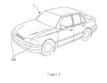
- FIG. 1 is a view showing the outer appearance of a transportation (vehicle) according to the embodiment
- FIG. 2 is a view showing a headlight apparatus shown in FIG. 1 ;
- FIG. 3 is a block diagram showing the headlight apparatus according to the embodiment.
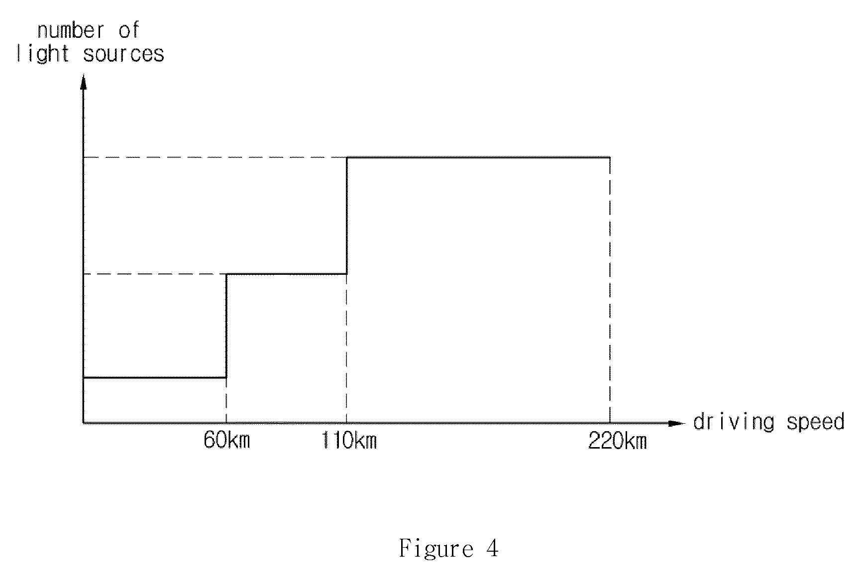
- FIG. 4 is a graph showing the number of the light sources as a function of a travelling speed according to the embodiment
- FIG. 5 is a graph showing the brightness of the light source as a function of the travelling speed according to the embodiment.
- FIG. 6 is a graph showing the brightness of the light source as a function of an ambient illuminance according to the embodiment
- FIG. 7 is a graph showing the number of light sources as a function of the ambient illuminance according to the embodiment.
- FIG. 8 is a graph showing the brightness of the light source as a function of the ambient illuminance according to the embodiment.
- FIGS. 9 to 11 are flowcharts showing a method of controlling the headlight apparatus according to the embodiment step by step.
- FIG. 1 is a view showing the outer appearance of a transportation (vehicle) according to the embodiment.
- the transportation may include a vehicle, an electric vehicle, a train, a motorcycle, a ship, a bicycle, and an airplane.
- the transportation is a vehicle
- the transportation may include any one of the electric vehicle, the train, the motorcycle, the ship, the bicycle, and the airplane, as well as the vehicle to be described below.
- a vehicle C includes many parts, the main parts of the vehicle C may be classified into a body and a chassis.
- the body accommodates humans or freights, and may have various shapes according to the uses of the vehicle such as a car, a bus, or a truck.
- the body includes an engine room and a trunk.
- the chassis refers to the remaining parts except for the body of the vehicle, and is equipped with a power transmission device, a steering device, and a driving device, as well as an engine supplying a driving force when the vehicle is driven.
- the engine generates power required to drive the vehicle.
- the engine for the vehicle mainly includes a gasoline engine, a diesel engine, and an LPG engine.
- the engine is configured by several attached equipment to perform a lubricating operation, a fuel supplying operation, a cooling operation, an intake operation, an outtake operation, a starting operation, and an ignition operation together with the body.
- the power transmission device refers to a series of devices to transfer the power generated from the engine to a driving wheel, and includes a clutch and a transmission.
- a braking device stops or decelerates a travelling vehicle by using a friction brake, or firmly parks the vehicle.
- Tires and wheels have a structure to endure the load burdened thereon, serve as a buffer, and endure several forces, such as a driving force and a braking force, generated when the vehicle is travelled.
- the steering device is used to arbitrarily change the moving direction of the vehicle. In other words, as a driver rotates the steering handle in the direction in which the drive wants to move the vehicle, the direction of the front wheel of the vehicle cooperating with the steering wheel may be changed.
- the vehicle C is provided on an outer appearance thereof with a headlight apparatus 100 to lighten the front of the vehicle when the vehicle C is driven at night and a turn signal to show the moving direction of the vehicle C to front/rear vehicles when the vehicle C turns the moving direction thereof.
- turn signals are positioned at the front surface, the rear surface, the left side, and the right side of the vehicle. If a driver manipulates a lighting button for an emergency light under the emergency situation, as left/right turn signals provided on the front surface of the vehicle C and left/right turn signals provided on the rear surface of the vehicle C are simultaneously turned on/off, the emergency situation is informed to the outside.
- FIG. 2 is a view showing a headlight apparatus shown in FIG. 1 .
- the headlight apparatus includes a housing 110 and a lens 120.
- the housing 110 is coupled with the body (not shown) and provided therein with a light source 112.
- the housing 110 is provided therein with a reflector 114.
- the reflector 114 reflects light emitted from the light source 12.
- the light source 112 may include a light emitting diode (LED).
- the reflector 114 may be deformed in the various shapes, and installed in the housing 110 through various schemes.
- the housing 110 has one side that is open, so that the light emitted from the light source 112 may be irradiated to the outside.
- FIG. 2 shows the case that the front side of the housing 110 is open for the convenience of explanation.
- housing 110 may be deformed in various shapes.
- the lens 120 closes one side of the housing 110, which is open, to protect the light source 112 and the reflector 114 provided in the housing 110.
- the lens 120 prevents foreign matters from being introduced into the housing 110.
- the lens 120 includes a transparent material to transmit the light irradiated thereto.
- the housing 110 may be coupled with the lens 120 through various schemes.
- the lens 120 includes a plastic material.
- the lens 120 includes poly carbonate (PC).
- PC poly carbonate
- the PC is a kind of plastic resin that has been extensively utilized from home appliances such as a coffee maker and an iron to high-tech products such as vehicle parts and cases of cellular phones.
- Headlight apparatuses described above are provided at the left and right sides of the vehicle C.
- the headlight apparatuses include a left-side headlight apparatus positioned at the left side of the vehicle C and a right-side headlight apparatus provided positioned at the right side of the vehicle C.
- each headlight apparatus includes a plurality of light sources (light emitting devices).
- the left-side headlight apparatus includes a plurality of light sources
- right-side headlight apparatus includes a plurality of light sources
- the light sources are selectively driven according to the travelling state of the vehicle C or the surrounding condition to emit light having predetermined brightness.
- FIG. 3 is a block diagram showing the headlight apparatus according to the embodiment.
- the headlight apparatus 100 includes a light source unit 210 including a plurality of light sources, a light source driving unit 220 to supply driving current to each light source constituting the light source unit 210, a power supply unit 230 to supply the driving power to a control unit 240, and the control unit 240 to determine the driving condition of the light source unit 210 and output a control signal to the light source driving unit 220 such that the light source unit 210 is driven according to the driving conditions.
- the light source unit 210 includes a plurality of light sources, and the light sources may be realized by using light emitting diodes (LEDs).
- LEDs light emitting diodes
- the light source unit 210 may include a left-side light source provided at the left front side of the vehicle C to emit light and a right-side light source provided at the right front side of the vehicle C to emit light.
- the light source unit 210 may include first to fourth light sources. Meanwhile, although drawings show that the light source unit 210 includes four light sources, the four light sources are provided only for illustrative purpose. In other words, the number of the light sources may be increased or decreased. For example, the light source unit 210 may include three light sources, or five light sources.
- the light source unit 210 may include a plurality of light sources as described above, the light source unit 210 may include one light source.
- the description will be made on the assumption that the light source unit 210 includes four light sources including first to fourth light sources.
- parts of light sources constituting the light source unit 210 act as downlights, and remaining parts of the light sources act as uplights.
- the first, second, and third light sources of the light source unit 210 may act as downlights, and the fourth source may act an uplight.
- the light source driving unit 220 supplies driving current to drive the light source unit 210.
- the light source driving unit 220 is connected to each light source of the light source unit 210 to supply the driving current to the light source.
- the light source driving unit 220 supplies driving current corresponding to appropriate driving brightness to a light source to be operated in the first state among the plural light sources.
- the light source driving unit 220 does not supply driving current to a light source to be operated in the second state among the plural light sources.
- the first state refers to an on-state representing that light is emitted
- the second state refers to an off-state representing that the light is not emitted.
- the power supply unit 230 generates the driving power of the control unit 240, and the generated driving power is supplied to the control unit 240.
- the power supply unit 230 may be realized by using a DC-DC converter to receive current from the light source driving unit 220 and convert the received current corresponding to the current required by the control unit 240.
- the control unit 240 determines the driving condition of the light source unit 210 and outputs a control signal to the light source driving unit 220 so that the light source unit 210 is driven according to the driving condition.
- control unit 240 receives at least one piece of information, which is used to determine the driving condition, from the outside.
- the information may include speed information according to the operating state of a vehicle.
- the control unit 240 is connected to an electronic control unit (ECU) to receive the speed information according to the operating state of the vehicle.
- ECU electronice control unit
- the information may include the information about the illuminance according to external surrounding conditions.
- the control unit 240 receives the information about the illuminance according to external surrounding conditions through an illuminance sensor.
- control unit 240 may control the on/off-state of the light source unit 210 by using the information about the illuminance.
- the control unit 240 turns off the light source 210. If the ambient illuminance is equal to or less than the present reference value, the light source unit 210 is turned on.
- control unit 240 determines the driving condition of the light source unit 210 by using any one of the speed information and the illuminance information in the state that the light source unit 210 is turned on, and controls the driving of the light source unit 210 according to the determined driving condition.
- the driving conditions may include the number of light sources to be driven and the brightness of the driven light source.
- control unit 240 may determine the driving condition of the light source unit 210 by using both of the speed information and the illuminance information, the control unit 240 may determine the driving condition by using only one of the speed information and the illuminance information.
- the control unit 240 receives the speed information and determines the light source to be operated in the first state by using the received speed information. In other words, the control unit 240 determines the number of light sources to be operated in the on-state by using the speed information.
- the number of the light sources may be increased or decreased in proportion to the increase or the decrease of the received speed information.
- FIG. 4 is a graph showing the number of the light sources as a function of a travelling speed according to the embodiment.
- the control unit 240 may make a determination so that only one of the first to fourth light sources is operated in the first state.
- the light source operated in the first state is preferably one of light sources acting as downlights.
- the control unit 240 allows only the first light source to operate in the first state, and allows the second and third light sources to operate in the second state. In this case, since the fourth light source acts as the uplight, the fourth light source maintains the second state.
- control unit 240 allows the first and second light sources to operate in the first state, and the third light source to operate in the second state.
- control unit 240 may allow the first to third light sources to operate in the first state.
- the range of the speed information used to determine the number of the light sources is more finely divided so that the light sources operating in the first state can be determined.
- control unit 240 increases the number of the light sources operating in the first state, so that the number of the light sources to emit light may be increased as the speed of the vehicle is increased.
- control unit 240 determines the brightness of each light source operating in the first state.
- the brightness of the light source may be increased or decreased in proportion to the speed information.
- FIG. 5 is a graph showing the brightness of the light source as a function of the travelling speed according to the embodiment.
- the control unit 240 increases the brightness of the light source by the increase of the travelling speed.
- control unit 240 increases the driving current supplied to the light source operating in the first state by increase of the travelling speed.
- the driving current supplied to the light source may be increased from 1A to 2A.
- the driving current supplied to the light source may be increased from 2A to 1A.
- the variation of the travelling speed sharply occurs under the sudden acceleration or the sudden stop, so that the variation in the brightness of the light source may rapidly occur.
- the brightness of the light source may be instantly decreased to 2-level brightness.
- the control unit 240 gradually changes the brightness of the light source, so that the driver can safely drive the vehicle.
- control unit 240 primarily maintains the brightness of the light source to a 10-level during the preset time, and decreases the brightness of the light source to the 2-level at the time point at which the preset time elapses.
- the gradual decrease of the brightness of the light source or the maintaining of the previous brightness of the light source during predetermined time may be applied when the variation between a previous travelling speed and a present travelling speed exceeds the preset value.
- the function is not applied. If the variation of the travelling speed exceeds 30 km, the gradual decrease of the brightness of the light source or the maintaining of the previous brightness of the light source during predetermined time may be applied.
- the maintaining of the previous brightness of the light source during predetermined time or the gradual decrease of the brightness of the light source is applied so that a driver may safely drive.
- the travelling speed is decreased as described above, the number of the light sources operating in the first state can be decreased.
- the third light source operating in the first state is changed to the second state.
- FIG. 6 is a graph showing the brightness of the light source as a function of an ambient illuminance according to the embodiment.
- the brightness of the light source changed to the second state is decreased in inverse proportion to the time, so that the brightness of the light source is gradually decreased.
- the control unit 240 receives the illuminance information and determines the light source to be operated in the first state by using the received illuminance information. In other words, the control unit 240 determines the number of the light sources to be operated in the on-state by using the illuminance information.
- the number of the light sources may be increased or decreased in inverse proportion to the increase or decrease of the received illuminance information.
- FIG. 7 is a graph showing the number of light sources as a function of the ambient illuminance according to the embodiment.
- the control unit 240 may make a determination so that three light sources among the first to fourth light sources operate in the first state if the ambient illuminance belongs to the range of 0 lux to 40 lux. In this case, since at least one of the first to fourth light sources acts as an uplight, the light source operating in the first state preferably acts as the downlight.
- the control unit 240 allows the first to third light sources to operate in the first state. In this case, since the fourth light source acts as the uplight, the fourth light source is maintained in the second state.
- control unit 240 allows all of the first to third light sources to operate in the second state.
- the range of the illuminance information to determine the number of the light sources is more finely divided, so that the light sources operating in the first state can be determined.
- control unit 240 decreases the number of the light sources operating in the first state as the ambient illuminance is increased, so that the number of the light sources to emit light is increased as the surrounding of the vehicle becomes dark.
- control unit 240 determines the brightness of each light source operating in the first state.
- the brightness of the light source may be increased or decreased in inverse proportion to the illuminance information.
- the control unit 240 decreases the brightness of the light source by the increase of the ambient illuminance.
- control unit 240 increases the driving current supplied to the light source operating in the first state by the decrease of the ambient illuminance.
- the driving current supplied to the light source may be increased from 1A to 2A.
- the driving current supplied to the light source may be decreased to 1A from 2A.
- control unit 240 applies the gradual decrease of the brightness of the light source and the maintaining of the previous brightness of the light source during predetermined time according to the brightness of the ambient illuminance.
- the light source unit includes a plurality of light sources
- one light source unit 210 may be provided.
- control unit 240 determines the driving current to be supplied to one light source unit 210 by using the speed information or the illuminance information.
- the light source 210 emits light having the brightness corresponding to the driving current determined through the controller 240.
- the brightness can be changed according to the speed information or the illuminance information.
- the brightness of the headlight apparatus is automatically changed in reaction to the travelling speed or the ambient illuminance of the vehicle, so that the reaction time to the obstacle provided at the front of the vehicle can be ensured, thereby allowing a driver to safely drive.
- control unit 240 receives the speed information or the information about the ambient illuminance according to the operating state of the vehicle (step S101).
- control unit 240 determines if the received speed information or the received information about the ambient illuminance is changed (step S102). In other words, the control unit 240 determines if the travelling speed of the vehicle is increased or decreased as compared with a previous travelling speed, or determines if the ambient illuminance becomes brighten or dark as compared with previous ambient illuminance .
- the light source driving unit 220 selectively supplies the driving current to the light sources constituting the light source unit 210 by using the driving condition determined through the control unit 240 (step S104).
- control unit 240 determines the light source to be operated in the first state among the plural light sources by using the speed information or the ambient illuminance (step S201).
- control unit 240 determines the number of the light sources to be operated in the first sate among the plural light sources.
- the number of the light sources to be operated in the first state is increased or decreased in proportion to the travelling speed, or in inverse proportion to the ambient illuminance.
- control unit 240 determines the brightness the light source operated in the first state (step S202).
- control unit 240 determines the driving current value to be supplied to the light source to be operated in the first state.
- the driving current value is increased or decreased in proportion to the travelling speed, or in inverse proportion to the ambient illuminance.
- control unit 240 determines if the number of the light source operating in the first state is decreased (step S301).
- control unit 240 determines if the light source subject to the state transition to the second state exists among the light sources operating in the first state.
- step S301 if the number of the light sources is decreased, the stopped light source (to be operated in the second state) is determined (step S302).
- control unit 240 gradually decreases the brightness of the light source (step S303).
- control unit 240 changes the light source having gradually decreased brightness to the second state (step S304).
- the brightness of the headlight apparatus is automatically changed in reaction to the travelling speed or the ambient illuminance of the vehicle, so that the reaction time to the obstacle provided at the front of the vehicle can be ensured, thereby allowing a driver to safely drive.
- any reference in this specification to "one embodiment,” “an embodiment,” “example embodiment,” etc. means that a particular feature, structure, or characteristic described in connection with the embodiment is included in at least one embodiment of the invention.
- the appearances of such phrases in various places in the specification are not necessarily all referring to the same embodiment.
Landscapes
- Engineering & Computer Science (AREA)
- Mechanical Engineering (AREA)
- General Engineering & Computer Science (AREA)
- Physics & Mathematics (AREA)
- Microelectronics & Electronic Packaging (AREA)
- Optics & Photonics (AREA)
- Lighting Device Outwards From Vehicle And Optical Signal (AREA)
Abstract

Description
- The embodiment relates to a headlight apparatus and a method of controlling the same.
- In general, a halogen lamp or a gas discharge lamp has been mainly used as a light source of the headlight of a vehicle.
- Since the halogen lamp represents red-based colors having the color temperature of about 3200k and has the life span of up to 1000 hours, the halogen lamp has been continuously issued in the related fields.
- In contrast, since the gas discharge lamp has the color temperature of about 4300K, the gas discharge lamp substantially represents white color. In addition, since the gas discharge lamp has the long life span, the gas discharge lamp is mainly used for a luxury car even though the price of the gas charge lamp is high.
- Meanwhile, since the light emitting diode (LED) has the color temperature of about 5500K almost approximating to that of the sunlight to cause the least eye fatigue to a human, the LED has been spotlighted as the light source of a headlamp of a vehicle recently.
- In addition, the size of the LED is minimized to increase the design free degree, and has an economic feasibility due to the semi-permanent life span.
- Recently, as an adaptive front lighting system (AFLS) has been employed, a driving unit is installed in the lamp. Accordingly, the direction to irradiate the light is changed according to the moving direction of the vehicle, so that the sight of a driver is widened when the driver drives at night.
- In general, the headlamp includes a light source having the fixed brightness to generate the light having the fixed brightness.
- Accordingly, a scheme of changing the brightness of light emitted from the headlamp or changing the distance of emitting the light according to the driving conditions has been sought.
- The embodiment provides a headlight apparatus capable of changing the brightness of light emitted from a light source according to the travelling condition of a transportation and a method of controlling the same.
- In addition, the embodiment provides a headlight apparatus capable of controlling the distance of light emitted from the light source by increasing or decreasing the number of the light sources driven according to the travelling conditions of the transportation and a method of controlling the same.
- The technical objects to be accomplished in suggested embodiments are not limited to the technical objects, and other objects can be clearly comprehended from the following description by those skilled in the art.
- According to the embodiment, there is provided a headlight apparatus provided in a transportation. The headlight apparatus includes a light source unit including at least one light source and emitting a light in a forward direction of the transportation, a light source driving unit supplying a driving current to the at least one light source included in the light source unit, and a control unit receiving information about a travelling environment of the transportation and determining a driving condition of the light source unit by using the received information about the travelling environment. The driving condition of the light source unit includes a driving current value corresponding to a brightness of the at least one light source included in the light source unit.
- In addition, the driving condition of the light source unit includes a driving current value corresponding to a brightness of the at least one light source included in the light source unit.
- Further, the information about the travelling environment of the transportation includes at least one of speed information corresponding to a travelling speed of the transportation and illuminance information corresponding to an ambient illuminance of the transportation, and the driving current value is changed in proportion to the travelling speed, or changed in inverse proportion to the ambient illuminance.
- In addition, the control unit gradually changes the brightness of the at least one light source by using at least one third driving current value existing a first driving current value corresponding to a previous brightness of the at least one light source and a second driving current value corresponding to a present brightness of the at least one light source when a difference value between the previous brightness and the present brightness of the at least one light source exceeds a preset reference value.
- In addition, the control unit maintains supplying a driving current value corresponding to a previous brightness during a predetermined time when decreasing the brightness of the at least one light source.
- Further, light source unit includes a plurality of light sources, and the light sources are operated in any one of a first state corresponding to an on-state and a second state corresponding to an off-state, and the driving condition of the light source unit further includes a number of the light sources to be operated in the first state among the plural light sources.
- In addition, the number of the light sources to be operated in the first state is increased or decreased in proportion to the travelling speed or in inverse proportion to the ambient illuminance.
- In addition, the control unit gradually decreases a brightness of the light source to be changed from the first state to the second state as the number of the light sources to be operated in the first state is decreased, and operates the light source in the second state as the brightness of the light source is gradually decreased.
- Meanwhile, according to the embodiment, there is provided a method of controlling a headlight apparatus including at least one light source. The method includes receiving information about a travelling environment of a transportation, determining a driving condition of the light source unit by using the received information about the travelling environment, and operating the light source by using the determined driving condition. The determining of the driving condition of the light source includes determining a brightness of a light to be emitted from the light source.
- The receiving information about the travelling environment of the transportation includes receiving at least one of speed information corresponding to a travelling speed of the transportation and illuminance information corresponding to an ambient illuminance of the transportation, and the brightness of the light to be emitted from the light source is changed in proportion to the travelling speed, or changed in inverse proportion to the ambient illuminance.
- Further, the operating of the light source by using the driving condition includes operating the light source in a first operation such that the light source represents a brightness existing between a present brightness of the light source, which is determined, and a previous brightness, and gradually changing the brightness of the light source by operating the light source in a second operation such that the light source represents the present brightness of the light source which is determined.
- In addition, the driving condition of the light source, which is determined, is applied at a time point after a predetermined time elapses from a determination time point, and the driving condition of the light source, which is previously determined, is applied until the predetermined time elapses.
- Further, the headlight apparatus includes a plurality of light sources, and the light sources are operated in any one of a first state corresponding to an on-state and a second state corresponding to an off-state, and the determining of the driving condition of the light source unit further includes determining a number of the light sources to be operated in the first state among the plural light sources.
- Further, the number of the light sources to be operated in the first state is increased or decreased in proportion to the travelling speed, or in inverse proportion to the ambient illuminance.
- In addition, the method further includes determining the light sources to be changed from the first state to the second state if the number of the light sources to be operated in the first state is decreased, and gradually decreasing the brightness of the determined light sources such that the determined light sources are operated in the second state.
- As described above, according to the embodiment, the brightness' of the headlight is automatically changed in reaction to the travelling speed or the ambient illuminance of the vehicle, so that the reaction time to the obstacle provided at the front of the vehicle can be ensured, thereby allowing a driver to safely drive.
- Meanwhile, other various effects of the embodiment will be directly or indirectly disclosed in the following detailed description of the embodiment.
-
FIG. 1 is a view showing the outer appearance of a transportation (vehicle) according to the embodiment; -
FIG. 2 is a view showing a headlight apparatus shown inFIG. 1 ; -
FIG. 3 is a block diagram showing the headlight apparatus according to the embodiment; -
FIG. 4 is a graph showing the number of the light sources as a function of a travelling speed according to the embodiment; -
FIG. 5 is a graph showing the brightness of the light source as a function of the travelling speed according to the embodiment; -
FIG. 6 is a graph showing the brightness of the light source as a function of an ambient illuminance according to the embodiment; -
FIG. 7 is a graph showing the number of light sources as a function of the ambient illuminance according to the embodiment; -
FIG. 8 is a graph showing the brightness of the light source as a function of the ambient illuminance according to the embodiment; and -
FIGS. 9 to 11 are flowcharts showing a method of controlling the headlight apparatus according to the embodiment step by step. -
FIG. 1 is a view showing the outer appearance of a transportation (vehicle) according to the embodiment. - In this case, the transportation may include a vehicle, an electric vehicle, a train, a motorcycle, a ship, a bicycle, and an airplane.
- Hereinafter, for the convenience of explanation, an example that the transportation is a vehicle will be described. However, the transportation may include any one of the electric vehicle, the train, the motorcycle, the ship, the bicycle, and the airplane, as well as the vehicle to be described below.
- Referring to
FIG. 1 , although a vehicle C includes many parts, the main parts of the vehicle C may be classified into a body and a chassis. - The body accommodates humans or freights, and may have various shapes according to the uses of the vehicle such as a car, a bus, or a truck.
- The body includes an engine room and a trunk.
- The chassis refers to the remaining parts except for the body of the vehicle, and is equipped with a power transmission device, a steering device, and a driving device, as well as an engine supplying a driving force when the vehicle is driven.
- The engine generates power required to drive the vehicle. The engine for the vehicle mainly includes a gasoline engine, a diesel engine, and an LPG engine. The engine is configured by several attached equipment to perform a lubricating operation, a fuel supplying operation, a cooling operation, an intake operation, an outtake operation, a starting operation, and an ignition operation together with the body.
- The power transmission device refers to a series of devices to transfer the power generated from the engine to a driving wheel, and includes a clutch and a transmission.
- A braking device stops or decelerates a travelling vehicle by using a friction brake, or firmly parks the vehicle. Tires and wheels have a structure to endure the load burdened thereon, serve as a buffer, and endure several forces, such as a driving force and a braking force, generated when the vehicle is travelled.
- The steering device is used to arbitrarily change the moving direction of the vehicle. In other words, as a driver rotates the steering handle in the direction in which the drive wants to move the vehicle, the direction of the front wheel of the vehicle cooperating with the steering wheel may be changed.
- The vehicle C is provided on an outer appearance thereof with a
headlight apparatus 100 to lighten the front of the vehicle when the vehicle C is driven at night and a turn signal to show the moving direction of the vehicle C to front/rear vehicles when the vehicle C turns the moving direction thereof. - In particular, turn signals are positioned at the front surface, the rear surface, the left side, and the right side of the vehicle. If a driver manipulates a lighting button for an emergency light under the emergency situation, as left/right turn signals provided on the front surface of the vehicle C and left/right turn signals provided on the rear surface of the vehicle C are simultaneously turned on/off, the emergency situation is informed to the outside.
-
FIG. 2 is a view showing a headlight apparatus shown inFIG. 1 . - Referring to
FIG. 2 , the headlight apparatus includes ahousing 110 and alens 120. - The
housing 110 is coupled with the body (not shown) and provided therein with alight source 112. In addition, thehousing 110 is provided therein with areflector 114. Thereflector 114 reflects light emitted from the light source 12. - In this case, the
light source 112 may include a light emitting diode (LED). Thereflector 114 may be deformed in the various shapes, and installed in thehousing 110 through various schemes. - In particular, the
housing 110 has one side that is open, so that the light emitted from thelight source 112 may be irradiated to the outside.FIG. 2 shows the case that the front side of thehousing 110 is open for the convenience of explanation. - Naturally, the
housing 110 may be deformed in various shapes. - Meanwhile, the
lens 120 closes one side of thehousing 110, which is open, to protect thelight source 112 and thereflector 114 provided in thehousing 110. - In addition, the
lens 120 prevents foreign matters from being introduced into thehousing 110. - In particular, the
lens 120 includes a transparent material to transmit the light irradiated thereto. - In this case, the
housing 110 may be coupled with thelens 120 through various schemes. - Meanwhile, the
lens 120 includes a plastic material. - In particular, the
lens 120 includes poly carbonate (PC). In this case, the PC is a kind of plastic resin that has been extensively utilized from home appliances such as a coffee maker and an iron to high-tech products such as vehicle parts and cases of cellular phones. - Headlight apparatuses described above are provided at the left and right sides of the vehicle C.
- In other words, the headlight apparatuses include a left-side headlight apparatus positioned at the left side of the vehicle C and a right-side headlight apparatus provided positioned at the right side of the vehicle C.
- In this case, each headlight apparatus includes a plurality of light sources (light emitting devices).
- In other words, the left-side headlight apparatus includes a plurality of light sources, and right-side headlight apparatus includes a plurality of light sources.
- In this case, the light sources are selectively driven according to the travelling state of the vehicle C or the surrounding condition to emit light having predetermined brightness.
- Hereinafter, the headlight apparatus will be described in more detail.
-
FIG. 3 is a block diagram showing the headlight apparatus according to the embodiment. - Referring to
FIG. 3 , theheadlight apparatus 100 includes alight source unit 210 including a plurality of light sources, a lightsource driving unit 220 to supply driving current to each light source constituting thelight source unit 210, apower supply unit 230 to supply the driving power to acontrol unit 240, and thecontrol unit 240 to determine the driving condition of thelight source unit 210 and output a control signal to the lightsource driving unit 220 such that thelight source unit 210 is driven according to the driving conditions. - The
light source unit 210 includes a plurality of light sources, and the light sources may be realized by using light emitting diodes (LEDs). - The
light source unit 210 may include a left-side light source provided at the left front side of the vehicle C to emit light and a right-side light source provided at the right front side of the vehicle C to emit light. - The
light source unit 210 may include first to fourth light sources. Meanwhile, although drawings show that thelight source unit 210 includes four light sources, the four light sources are provided only for illustrative purpose. In other words, the number of the light sources may be increased or decreased. For example, thelight source unit 210 may include three light sources, or five light sources. - Meanwhile, although the
light source unit 210 may include a plurality of light sources as described above, thelight source unit 210 may include one light source. - Hereinafter, the description will be made on the assumption that the
light source unit 210 includes four light sources including first to fourth light sources. - In this case, parts of light sources constituting the
light source unit 210 act as downlights, and remaining parts of the light sources act as uplights. - For example, the first, second, and third light sources of the
light source unit 210 may act as downlights, and the fourth source may act an uplight. - The light
source driving unit 220 supplies driving current to drive thelight source unit 210. - In particular, the light
source driving unit 220 is connected to each light source of thelight source unit 210 to supply the driving current to the light source. - In other words, the light
source driving unit 220 supplies driving current corresponding to appropriate driving brightness to a light source to be operated in the first state among the plural light sources. In addition, the lightsource driving unit 220 does not supply driving current to a light source to be operated in the second state among the plural light sources. - In this case, the first state refers to an on-state representing that light is emitted, and the second state refers to an off-state representing that the light is not emitted.
- The
power supply unit 230 generates the driving power of thecontrol unit 240, and the generated driving power is supplied to thecontrol unit 240. - In this case, the
power supply unit 230 may be realized by using a DC-DC converter to receive current from the lightsource driving unit 220 and convert the received current corresponding to the current required by thecontrol unit 240. - The
control unit 240 determines the driving condition of thelight source unit 210 and outputs a control signal to the lightsource driving unit 220 so that thelight source unit 210 is driven according to the driving condition. - Hereinafter, a scheme of driving the
light source unit 210 will be described in detail. - First, the
control unit 240 receives at least one piece of information, which is used to determine the driving condition, from the outside. - In this case, the information may include speed information according to the operating state of a vehicle. To this end, the
control unit 240 is connected to an electronic control unit (ECU) to receive the speed information according to the operating state of the vehicle. - In addition, the information may include the information about the illuminance according to external surrounding conditions. To this end, the
control unit 240 receives the information about the illuminance according to external surrounding conditions through an illuminance sensor. - In this case, if the information about illuminance is received, the
control unit 240 may control the on/off-state of thelight source unit 210 by using the information about the illuminance. - For example, if the ambient illuminance according to the information of the illuminance is greater than or equal to a preset reference value, the
control unit 240 turns off thelight source 210. If the ambient illuminance is equal to or less than the present reference value, thelight source unit 210 is turned on. - In addition, the
control unit 240 determines the driving condition of thelight source unit 210 by using any one of the speed information and the illuminance information in the state that thelight source unit 210 is turned on, and controls the driving of thelight source unit 210 according to the determined driving condition. - In this case, the driving conditions may include the number of light sources to be driven and the brightness of the driven light source.
- Meanwhile, although the
control unit 240 may determine the driving condition of thelight source unit 210 by using both of the speed information and the illuminance information, thecontrol unit 240 may determine the driving condition by using only one of the speed information and the illuminance information. - Hereinafter, a process of determining the driving condition by using the speed information will be described.
- The
control unit 240 receives the speed information and determines the light source to be operated in the first state by using the received speed information. In other words, thecontrol unit 240 determines the number of light sources to be operated in the on-state by using the speed information. - In this case, the number of the light sources may be increased or decreased in proportion to the increase or the decrease of the received speed information.
-
FIG. 4 is a graph showing the number of the light sources as a function of a travelling speed according to the embodiment. - Referring to
FIG. 4 , if the received speed information belongs to the range of 0 km to 60 km, thecontrol unit 240 may make a determination so that only one of the first to fourth light sources is operated in the first state. In this case, since at least one of the first to fourth light sources acts as an uplight, the light source operated in the first state is preferably one of light sources acting as downlights. - In other words, if the first to third light sources act as downlights, and if the speed information belongs to the range of 0 km to 60 km, the
control unit 240 allows only the first light source to operate in the first state, and allows the second and third light sources to operate in the second state. In this case, since the fourth light source acts as the uplight, the fourth light source maintains the second state. - If the speed information belongs to the range of 60 km to 110 km, the
control unit 240 allows the first and second light sources to operate in the first state, and the third light source to operate in the second state. - In addition, if the speed information belongs to the range of 110 km to 220 km, the
control unit 240 may allow the first to third light sources to operate in the first state. - As the number of the light sources acting as the downlights is increased, the range of the speed information used to determine the number of the light sources is more finely divided so that the light sources operating in the first state can be determined.
- As described above, as the received travelling speed is increased, the
control unit 240 increases the number of the light sources operating in the first state, so that the number of the light sources to emit light may be increased as the speed of the vehicle is increased. - If the number of the light sources operating in the first sate is determined, the
control unit 240 determines the brightness of each light source operating in the first state. - In this case, the brightness of the light source may be increased or decreased in proportion to the speed information.
-
FIG. 5 is a graph showing the brightness of the light source as a function of the travelling speed according to the embodiment. - Referring to
FIG. 5 , if the travelling speed is increased, thecontrol unit 240 increases the brightness of the light source by the increase of the travelling speed. - To this end, if the travelling speed is increased, the
control unit 240 increases the driving current supplied to the light source operating in the first state by increase of the travelling speed. - For example, if the travelling speed is increased to 60 km in the state that the driving current of 1A is supplied to the light source at the speed of 50 km, the driving current supplied to the light source may be increased from 1A to 2A.
- In contrast, if the travelling speed is decreased to 50 km in the state that the driving current of 2A is supplied to the light source at the speed of 60 km, the driving current supplied to the light source may be increased from 2A to 1A.
- In this case, the variation of the travelling speed sharply occurs under the sudden acceleration or the sudden stop, so that the variation in the brightness of the light source may rapidly occur.
- For example, if the sudden stop to the travelling speed of 20 km occurs in the state that the light source is driven with the 10-level brightness at the travelling speed of 100 km, the brightness of the light source may be instantly decreased to 2-level brightness.
- In this case, if the brightness of the light source is instantly decreased, a driver may not safely drive the vehicle. Accordingly, if the brightness of the light source is decreased, the
control unit 240 gradually changes the brightness of the light source, so that the driver can safely drive the vehicle. - For example, as described above, if the sudden stop to the travelling speed of 20 km occurs in the state that the light source is driven with the 10-level brightness at the travelling speed of 100 km, the
control unit 240 sequentially decreases the brightness of the light source in the order of 8-level brightness, 6-level brightness, 4-level brightness, and 2-level brightness. - Alternatively, if the sudden stop to the travelling speed of 20 km occurs in the state that the light source is driven with the 10-level brightness at the travelling speed of 100 km as described above, the
control unit 240 primarily maintains the brightness of the light source to a 10-level during the preset time, and decreases the brightness of the light source to the 2-level at the time point at which the preset time elapses. - In this case, the gradual decrease of the brightness of the light source or the maintaining of the previous brightness of the light source during predetermined time may be applied when the variation between a previous travelling speed and a present travelling speed exceeds the preset value.
- For example, if the variation of the travelling speed is 20 km, the function is not applied. If the variation of the travelling speed exceeds 30 km, the gradual decrease of the brightness of the light source or the maintaining of the previous brightness of the light source during predetermined time may be applied.
- As described above, according to the embodiment, if the travelling speed is instantly decreased, the maintaining of the previous brightness of the light source during predetermined time or the gradual decrease of the brightness of the light source is applied so that a driver may safely drive.
- Meanwhile, if the travelling speed is decreased as described above, the number of the light sources operating in the first state can be decreased.
- For example, as shown in
FIG. 4 , in the state that all of the first to third light sources operate in the first state as the vehicle travels at the speed of 120 km, if the travelling speed is decreased to 100 km, the number of the light sources operating in the first state must be decreased. - Accordingly, the third light source operating in the first state is changed to the second state.
- In this case, if the third light source is instantly changed to the second state, the surrounding brightness becomes abruptly dark to interrupt the safe driving of the driver.
- Therefore, according to the embodiment, if the light source changed to the second state exists, the brightness of the light source is gradually decreased so that the light source is finally changed to the second state.
-
FIG. 6 is a graph showing the brightness of the light source as a function of an ambient illuminance according to the embodiment. - Referring to
FIG. 6 , according to the embodiment, if the light source, which must be changed to the second state, exists, the brightness of the light source changed to the second state is decreased in inverse proportion to the time, so that the brightness of the light source is gradually decreased. - For example, according to the embodiment, if the third light source must be changed to the second state in the state that the third light source is driven with the 10-level brightness, the brightness of the third light source is gradually decreased in the order of 10-level brightness, 7-level brightness, 4-level brightness, 1-level brightness, and 0-level brightness, and the third light source is finally changed to the second state.
- Hereinafter, a process of determining the driving condition by using the illuminance information will be described.
- The
control unit 240 receives the illuminance information and determines the light source to be operated in the first state by using the received illuminance information. In other words, thecontrol unit 240 determines the number of the light sources to be operated in the on-state by using the illuminance information. - In this case, the number of the light sources may be increased or decreased in inverse proportion to the increase or decrease of the received illuminance information.
-
FIG. 7 is a graph showing the number of light sources as a function of the ambient illuminance according to the embodiment. - Referring to
FIG. 7 , thecontrol unit 240 may make a determination so that three light sources among the first to fourth light sources operate in the first state if the ambient illuminance belongs to the range of 0 lux to 40 lux. In this case, since at least one of the first to fourth light sources acts as an uplight, the light source operating in the first state preferably acts as the downlight. - In other words, if the first to third light sources act as the downlights, and the illuminance information belongs to the range of 0 lux to 60 lux, the
control unit 240 allows the first to third light sources to operate in the first state. In this case, since the fourth light source acts as the uplight, the fourth light source is maintained in the second state. - In addition, if the illuminance information belongs to the range of 60 lux to 110 lux, the
control unit 240 allows the first and second light sources to operate in the first state, and allows the third light source to operate in the second state. - In addition, if the illuminance information is equal to or greater than 110 lux, the
control unit 240 may allow only the first light source to operate in the first state. - In addition, if the illuminance information exceeds a predetermined limitation value, the
control unit 240 allows all of the first to third light sources to operate in the second state. - Meanwhile, as the number of the light sources acting as the downlights is increased, the range of the illuminance information to determine the number of the light sources is more finely divided, so that the light sources operating in the first state can be determined.
- As described above, the
control unit 240 decreases the number of the light sources operating in the first state as the ambient illuminance is increased, so that the number of the light sources to emit light is increased as the surrounding of the vehicle becomes dark. - In addition, if the number of the light sources operating in the first state is determined, the
control unit 240 determines the brightness of each light source operating in the first state. - In this case, the brightness of the light source may be increased or decreased in inverse proportion to the illuminance information.
-
FIG. 8 is a graph showing the brightness of the light source as a function of the ambient illuminance according to the embodiment. - Referring to
FIG. 8 , if the ambient illuminance is increased, thecontrol unit 240 decreases the brightness of the light source by the increase of the ambient illuminance. - To this end, if the ambient illuminance is decreased, the
control unit 240 increases the driving current supplied to the light source operating in the first state by the decrease of the ambient illuminance. - For example, if the ambient illuminance is decreased to 90 lux in the state that the driving current of 1A is supplied to the light source at the illuminance of 100 lux, the driving current supplied to the light source may be increased from 1A to 2A.
- In contrast, if the ambient illuminance is increased to 100 lux in the state that the driving current of 2A is supplied to the light source at the illuminance of 50 lux, the driving current supplied to the light source may be decreased to 1A from 2A.
- In addition, the
control unit 240 applies the gradual decrease of the brightness of the light source and the maintaining of the previous brightness of the light source during predetermined time according to the brightness of the ambient illuminance. - Since the decrease function and the maintaining function have been described based on the travelling speed, the details thereof will be omitted.
- Meanwhile, although an example that the light source unit includes a plurality of light sources has been described, one
light source unit 210 may be provided. - Accordingly, the
control unit 240 determines the driving current to be supplied to onelight source unit 210 by using the speed information or the illuminance information. Thelight source 210 emits light having the brightness corresponding to the driving current determined through thecontroller 240. - As described above, according to the embodiment, even if one
light source unit 210 is used, the brightness can be changed according to the speed information or the illuminance information. - According to the embodiment, the brightness of the headlight apparatus is automatically changed in reaction to the travelling speed or the ambient illuminance of the vehicle, so that the reaction time to the obstacle provided at the front of the vehicle can be ensured, thereby allowing a driver to safely drive.
-
FIGS. 9 to 11 are flowcharts showing a method of controlling the headlight apparatus according to the embodiment step by step. - Referring to
FIG. 9 , thecontrol unit 240 receives the speed information or the information about the ambient illuminance according to the operating state of the vehicle (step S101). - Thereafter, the
control unit 240 determines if the received speed information or the received information about the ambient illuminance is changed (step S102). In other words, thecontrol unit 240 determines if the travelling speed of the vehicle is increased or decreased as compared with a previous travelling speed, or determines if the ambient illuminance becomes brighten or dark as compared with previous ambient illuminance . - If the speed information or the ambient illuminance is changed as the determination result (step S102), the
control unit 240 determines the driving condition for a plurality of light sources constituting thelight source unit 210 by using the changed speed information or the changed ambient illuminance (step S103). - Thereafter, the light
source driving unit 220 selectively supplies the driving current to the light sources constituting thelight source unit 210 by using the driving condition determined through the control unit 240 (step S104). - Referring to
FIG. 10 , thecontrol unit 240 determines the light source to be operated in the first state among the plural light sources by using the speed information or the ambient illuminance (step S201). - In other words, the
control unit 240 determines the number of the light sources to be operated in the first sate among the plural light sources. - In this case, the number of the light sources to be operated in the first state is increased or decreased in proportion to the travelling speed, or in inverse proportion to the ambient illuminance.
- Thereafter, the
control unit 240 determines the brightness the light source operated in the first state (step S202). - In other words, the
control unit 240 determines the driving current value to be supplied to the light source to be operated in the first state. - In this case, the driving current value is increased or decreased in proportion to the travelling speed, or in inverse proportion to the ambient illuminance.
- Next, referring to
FIG. 11 , thecontrol unit 240 determines if the number of the light source operating in the first state is decreased (step S301). - In other words, the
control unit 240 determines if the light source subject to the state transition to the second state exists among the light sources operating in the first state. - As the determination result (step S301), if the number of the light sources is decreased, the stopped light source (to be operated in the second state) is determined (step S302).
- Thereafter, the
control unit 240 gradually decreases the brightness of the light source (step S303). - In addition, the
control unit 240 changes the light source having gradually decreased brightness to the second state (step S304). - According to the embodiment, the brightness of the headlight apparatus is automatically changed in reaction to the travelling speed or the ambient illuminance of the vehicle, so that the reaction time to the obstacle provided at the front of the vehicle can be ensured, thereby allowing a driver to safely drive.
- Any reference in this specification to "one embodiment," "an embodiment," "example embodiment," etc., means that a particular feature, structure, or characteristic described in connection with the embodiment is included in at least one embodiment of the invention. The appearances of such phrases in various places in the specification are not necessarily all referring to the same embodiment. Further, when a particular feature, structure, or characteristic is described in connection with any embodiment, it is submitted that it is within the purview of one skilled in the art to effect such feature, structure, or characteristic in connection with other ones of the embodiments.
- Although embodiments have been described with reference to a number of illustrative embodiments thereof, it should be understood that numerous other modifications and embodiments can be devised by those skilled in the art that will fall within the spirit and scope of the principles of this disclosure. More particularly, various variations and modifications are possible in the component parts and/or arrangements of the subject combination arrangement within the scope of the disclosure, the drawings and the appended claims. In addition to variations and modifications in the component parts and/or arrangements, alternative uses will also be apparent to those skilled in the art.
Claims (15)
- A headlight apparatus provided in a transportation, the headlight apparatus comprising:a light source unit (210) including at least one light source and emitting a light in a forward direction of the transportation;a light source driving unit (220) supplying a driving current to the at least one light source included in the light source unit (210); anda control unit (240) receiving information about a travelling environment of the transportation and determining a driving condition of the light source unit (210) by using the received information about the travelling environment.
- The headlight apparatus of claim 1, wherein the driving condition of the light source unit (210) includes a driving current value corresponding to a brightness of the at least one light source included in the light source unit (210).
- The headlight apparatus of claim 2, wherein the information about the travelling environment of the transportation includes at least one of speed information corresponding to a travelling speed of the transportation and illuminance information corresponding to an ambient illuminance of the transportation, and
wherein the driving current value is changed in proportion to the travelling speed, or changed in inverse proportion to the ambient illuminance. - The headlight apparatus of claim 2, wherein the control unit (240) gradually changes the brightness of the at least one light source by using at least one third driving current value existing a first driving current value corresponding to a previous brightness of the at least one light source and a second driving current value corresponding to a present brightness of the at least one light source when a difference value between the previous brightness and the present brightness of the at least one light source exceeds a preset reference value.
- The headlight apparatus of claim 2, wherein the control unit (240) maintains supplying a driving current value corresponding to a previous brightness during a predetermined time when decreasing the brightness of the at least one light source.
- The headlight apparatus of claim 3, wherein the light source unit (210) includes a plurality of light sources, and the light sources are operated in any one of a first state corresponding to an on-state and a second state corresponding to an off-state, and
wherein the driving condition of the light source unit (210) further includes a number of the light sources to be operated in the first state among the plural light sources. - The headlight apparatus of claim 6, wherein the number of the light sources to be operated in the first state is increased or decreased in proportion to the travelling speed or in inverse proportion to the ambient illuminance.
- The headlight apparatus of claim 6, wherein the control unit (240) gradually decreases a brightness of the light source to be changed from the first state to the second state as the number of the light sources to be operated in the first state is decreased, and operates the light source in the second state as the brightness of the light source is gradually decreased.
- A method of controlling a headlight apparatus including at least one light source, the method comprising:receiving information about a travelling environment of a transportation;determining a driving condition of the light source unit (210) by using the received information about the travelling environment; andoperating the light source by using the determined driving condition,wherein the determining of the driving condition of the light source includes determining a brightness of a light to be emitted from the light source.
- The method of claim 9, wherein the receiving information about the travelling environment of the transportation includes receiving at least one of speed information corresponding to a travelling speed of the transportation and illuminance information corresponding to an ambient illuminance of the transportation, and
wherein the brightness of the light to be emitted from the light source is changed in proportion to the travelling speed, or changed in inverse proportion to the ambient illuminance. - The method of claim 9, wherein the operating of the light source by using the driving condition includes:operating the light source in a first operation such that the light source represents a brightness existing between a present brightness of the light source, which is determined, and a previous brightness; andgradually changing the brightness of the light source by operating the light source in a second operation such that the light source represents the present brightness of the light source which is determined.
- The method of claim 9, wherein the driving condition of the light source, which is determined, is applied at a time point after a predetermined time elapses from a determination time point, and the driving condition of the light source, which is previously determined, is applied until the predetermined time elapses.
- The method of claim 9, wherein the headlight apparatus includes a plurality of light sources, and the light sources are operated in any one of a first state corresponding to an on-state and a second state corresponding to an off-state, and
wherein the determining of the driving condition of the light source unit (210) further includes determining a number of the light sources to be operated in the first state among the plural light sources. - The method of claim 13, wherein the number of the light sources to be operated in the first state is increased or decreased in proportion to the travelling speed, or in inverse proportion to the ambient illuminance.
- The method of claim 13, further comprising determining the light sources to be changed from the first state to the second state if the number of the light sources to be operated in the first state is decreased, and gradually decreasing the brightness of the determined light sources such that the determined light sources are operated in the second state.
Applications Claiming Priority (1)
| Application Number | Priority Date | Filing Date | Title |
|---|---|---|---|
| KR1020120108154A KR102023525B1 (en) | 2012-09-27 | 2012-09-27 | Head light apparatus and control method thereof |
Publications (3)
| Publication Number | Publication Date |
|---|---|
| EP2712764A2 true EP2712764A2 (en) | 2014-04-02 |
| EP2712764A3 EP2712764A3 (en) | 2018-04-18 |
| EP2712764B1 EP2712764B1 (en) | 2020-09-16 |
Family
ID=48537845
Family Applications (1)
| Application Number | Title | Priority Date | Filing Date |
|---|---|---|---|
| EP13170185.6A Active EP2712764B1 (en) | 2012-09-27 | 2013-05-31 | Headlight apparatus and method of controlling the same |
Country Status (4)
| Country | Link |
|---|---|
| US (1) | US9333903B2 (en) |
| EP (1) | EP2712764B1 (en) |
| JP (1) | JP6053615B2 (en) |
| KR (1) | KR102023525B1 (en) |
Families Citing this family (12)
| Publication number | Priority date | Publication date | Assignee | Title |
|---|---|---|---|---|
| US9586516B2 (en) * | 2014-02-28 | 2017-03-07 | Gentex Corporation | Headlight level control with residential detection mode |
| CN104057872B (en) * | 2014-06-08 | 2015-06-17 | 来安县新元机电设备设计有限公司 | Car prepositive light control method and system |
| JP2017525606A (en) * | 2014-08-05 | 2017-09-07 | 李 文嵩 | Smart light device for car |
| US9526155B2 (en) * | 2014-12-30 | 2016-12-20 | Google Inc. | Systems and methods of controlling light sources according to location |
| JP6587450B2 (en) * | 2015-08-07 | 2019-10-09 | 株式会社小糸製作所 | Vehicle lighting |
| US9773417B2 (en) * | 2016-01-08 | 2017-09-26 | Ford Global Technologies, Llc | Enhanced park assist system |
| US10343590B2 (en) * | 2017-05-31 | 2019-07-09 | Valeo North America, Inc. | Active headlight system and method |
| CN109383362B (en) * | 2017-08-04 | 2023-04-28 | 西安中兴新软件有限责任公司 | Automobile headlamp control method and device |
| CN108901110B (en) * | 2018-08-03 | 2020-03-10 | 重庆交通大学 | Energy-saving highway tunnel equivalent lighting control system |
| US10583776B1 (en) * | 2018-09-19 | 2020-03-10 | Luis R. Ortiz | Device and method for providing indication to rear vehicle depending on brake force applied by vehicle |
| CN109673076B (en) * | 2018-11-29 | 2021-08-20 | 重庆唯哲科技有限公司 | Lamplight synchronous display system for multi-equipment movement |
| JP2023086003A (en) | 2021-12-09 | 2023-06-21 | スタンレー電気株式会社 | Vehicle lighting control device, vehicle lighting control method, vehicle lighting system |
Family Cites Families (35)
| Publication number | Priority date | Publication date | Assignee | Title |
|---|---|---|---|---|
| US6861809B2 (en) * | 1998-09-18 | 2005-03-01 | Gentex Corporation | Headlamp control to prevent glare |
| US6049171A (en) * | 1998-09-18 | 2000-04-11 | Gentex Corporation | Continuously variable headlamp control |
| US5781105A (en) * | 1997-04-09 | 1998-07-14 | Ford Motor Company | Light management system for a vehicle |
| JP3782634B2 (en) * | 2000-01-11 | 2006-06-07 | 株式会社小糸製作所 | Auto-leveling device for automotive headlamps |
| JP2002087151A (en) * | 2000-09-19 | 2002-03-26 | Aisin Seiki Co Ltd | Vehicle lamp control device |
| US6447132B1 (en) * | 2001-02-20 | 2002-09-10 | Delphi Technologies, Inc. | Day/night HUD backlighting system |
| DE10225992A1 (en) * | 2002-06-12 | 2003-12-24 | Bosch Gmbh Robert | Method of controlling operating parameters of a vehicle lighting system by adjusting light intensity based on vehicle speed |
| JP4818609B2 (en) * | 2002-08-21 | 2011-11-16 | ジェンテックス コーポレイション | Image acquisition and processing method for automatic control of external vehicle lighting |
| JP2004276737A (en) | 2003-03-14 | 2004-10-07 | Koito Mfg Co Ltd | Vehicle lighting |
| JP2004276739A (en) | 2003-03-14 | 2004-10-07 | Koito Mfg Co Ltd | Vehicle lighting |
| DE10313337A1 (en) * | 2003-03-25 | 2004-10-21 | Brose Fahrzeugteile Gmbh & Co. Kommanditgesellschaft, Coburg | Triggering method for a lighting device/LED in a motor vehicle has an element for reducing or increasing luminous intensity and/or for adapting the LED's dynamics to preset parameters |
| JP3752492B2 (en) * | 2003-03-28 | 2006-03-08 | 株式会社シマノ | Bicycle hub |
| JP4170928B2 (en) * | 2004-02-18 | 2008-10-22 | 株式会社小糸製作所 | Vehicle lighting |
| CZ302547B6 (en) * | 2005-07-04 | 2011-07-07 | Visteon Global Technologies, Inc. | Adaptive headlight system of motor vehicles |
| EP1757486B1 (en) * | 2005-08-26 | 2014-04-30 | Nissan Motor Co., Ltd. | Device and method for controlling vehicle headlamps |
| JP2007253806A (en) | 2006-03-23 | 2007-10-04 | Mitsubishi Electric Corp | Headlight lighting control device |
| JP5028851B2 (en) * | 2006-04-24 | 2012-09-19 | 株式会社デンソー | Road information detection apparatus and program |
| JP4661759B2 (en) * | 2006-10-06 | 2011-03-30 | 株式会社デンソー | Vehicle lighting control system |
| US8770771B2 (en) * | 2007-03-15 | 2014-07-08 | Hans Christer Preta | Smart light with power backup |
| KR101396864B1 (en) * | 2007-11-15 | 2014-05-19 | 현대모비스 주식회사 | Apparatus for controlling LED head lamp for cars and method thereof |
| DE202007017871U1 (en) * | 2007-12-21 | 2009-04-23 | Willmann, Matthias | Automatic stop of the brake light |
| JP2009214812A (en) * | 2008-03-12 | 2009-09-24 | Koito Mfg Co Ltd | Vehicular headlight device and its control method |
| DE102008041355A1 (en) * | 2008-08-19 | 2010-02-25 | Robert Bosch Gmbh | Traffic situation adapted light energy saving function |
| JP5338372B2 (en) * | 2009-02-24 | 2013-11-13 | 株式会社デンソー | Vehicle power generation control device |
| US8135514B2 (en) * | 2009-03-26 | 2012-03-13 | GM Global Technology Operations LLC | Automotive systems and methods of operating vehicles |
| EP2289737B1 (en) * | 2009-08-26 | 2018-04-25 | Valeo Vision | Device and method for controlling the power supply of a headlamp |
| US9090207B2 (en) * | 2010-05-27 | 2015-07-28 | Boxx Corp. | Two wheeled vehicle with lighting system that generates defined image on riding surface |
| DE102010023583A1 (en) * | 2010-06-12 | 2011-12-15 | Automotive Lighting Reutlingen Gmbh | Method for operating vehicle headlight for vehicle, particularly motor vehicle, involves regulating or controlling semiconductor light source, particularly light emitting diode, by pulse width modulated signal |
| JP5348100B2 (en) * | 2010-09-17 | 2013-11-20 | トヨタ自動車株式会社 | Headlamp device, brightness control method |
| JP5752379B2 (en) * | 2010-09-22 | 2015-07-22 | 川崎重工業株式会社 | Vehicle bank angle detector |
| JP2012121521A (en) * | 2010-12-10 | 2012-06-28 | Denso Corp | Light quantity controller and light quantity control program |
| US8498779B2 (en) * | 2011-03-02 | 2013-07-30 | Stanley Electric Co., Ltd. | Headlight control apparatus for vehicles, and headlight system for vehicles |
| US8890435B2 (en) * | 2011-03-11 | 2014-11-18 | Ilumi Solutions, Inc. | Wireless lighting control system |
| JP2013043623A (en) * | 2011-08-26 | 2013-03-04 | Stanley Electric Co Ltd | Lighting control device of vehicle headlamp, and vehicle headlamp system |
| EP2636946B1 (en) * | 2012-03-08 | 2019-05-08 | Stanley Electric Co., Ltd. | Headlight controller |
-
2012
- 2012-09-27 KR KR1020120108154A patent/KR102023525B1/en active Active
-
2013
- 2013-01-14 US US13/740,840 patent/US9333903B2/en active Active
- 2013-05-31 EP EP13170185.6A patent/EP2712764B1/en active Active
- 2013-06-10 JP JP2013121548A patent/JP6053615B2/en active Active
Non-Patent Citations (1)
| Title |
|---|
| None |
Also Published As
| Publication number | Publication date |
|---|---|
| EP2712764B1 (en) | 2020-09-16 |
| KR20140041140A (en) | 2014-04-04 |
| JP6053615B2 (en) | 2016-12-27 |
| EP2712764A3 (en) | 2018-04-18 |
| JP2014069797A (en) | 2014-04-21 |
| US9333903B2 (en) | 2016-05-10 |
| KR102023525B1 (en) | 2019-09-20 |
| US20140084788A1 (en) | 2014-03-27 |
Similar Documents
| Publication | Publication Date | Title |
|---|---|---|
| EP2712764B1 (en) | Headlight apparatus and method of controlling the same | |
| US8057081B2 (en) | Light guide for vehicle lamp assembly | |
| KR101460720B1 (en) | Method for controling headlamp of automobile | |
| JP6018875B2 (en) | Lighting control system for vehicle lamp | |
| CN106585484B (en) | Vehicle rear lighting system | |
| US9242595B2 (en) | Apparatus and method for controlling taillight of vehicle, capable of brightness control and visible light wireless communication | |
| JP5761883B2 (en) | LED bulbs for replacing halogen bulbs for automobiles | |
| JP2017199520A (en) | LIGHTING DEVICE AND VEHICLE LIGHTING DEVICE EQUIPPED WITH THE SAME | |
| CN103945597A (en) | Headlamp arrangement for motor car | |
| KR20110092108A (en) | Automotive integrated LED lamp | |
| JP2014076726A (en) | Headlight control device for electric automobile | |
| KR100699690B1 (en) | Automotive lighting device using LED | |
| KR200461949Y1 (en) | Car Fog Light Module | |
| KR20130036609A (en) | Lamp apparatus for an automobile | |
| KR101393349B1 (en) | Method for controling headlamp of automobile | |
| CN108367706A (en) | Uniformity backlight systems for motor vehicles | |
| CN108800056B (en) | Optical structure of a car signal light | |
| US12403816B2 (en) | Method for operating a motor vehicle, and motor vehicle | |
| KR101349469B1 (en) | Head lamp and control method thereof | |
| EP4155127A1 (en) | Interior lamp for automobile and automobile using the same | |
| KR101913123B1 (en) | Head lamp and control method thereof | |
| CN205871891U (en) | Automobile rearview mirror with illumination function | |
| KR102526208B1 (en) | Lamp for electric vehicle | |
| KR100444159B1 (en) | Combined Side Lamp and Warning Lamp for Ambulance Using Light Emitting Diode | |
| US20220201819A1 (en) | Dummy load for automotive led light with charging and discharging function |
Legal Events
| Date | Code | Title | Description |
|---|---|---|---|
| PUAI | Public reference made under article 153(3) epc to a published international application that has entered the european phase |
Free format text: ORIGINAL CODE: 0009012 |
|
| AK | Designated contracting states |
Kind code of ref document: A2 Designated state(s): AL AT BE BG CH CY CZ DE DK EE ES FI FR GB GR HR HU IE IS IT LI LT LU LV MC MK MT NL NO PL PT RO RS SE SI SK SM TR |
|
| AX | Request for extension of the european patent |
Extension state: BA ME |
|
| 17P | Request for examination filed |
Effective date: 20140331 |
|
| RBV | Designated contracting states (corrected) |
Designated state(s): AL AT BE BG CH CY CZ DE DK EE ES FI FR GB GR HR HU IE IS IT LI LT LU LV MC MK MT NL NO PL PT RO RS SE SI SK SM TR |
|
| RAP1 | Party data changed (applicant data changed or rights of an application transferred) |
Owner name: LG INNOTEK CO., LTD. |
|
| PUAL | Search report despatched |
Free format text: ORIGINAL CODE: 0009013 |
|
| AK | Designated contracting states |
Kind code of ref document: A3 Designated state(s): AL AT BE BG CH CY CZ DE DK EE ES FI FR GB GR HR HU IE IS IT LI LT LU LV MC MK MT NL NO PL PT RO RS SE SI SK SM TR |
|
| AX | Request for extension of the european patent |
Extension state: BA ME |
|
| RIC1 | Information provided on ipc code assigned before grant |
Ipc: H05B 33/08 20060101ALI20180315BHEP Ipc: B60Q 1/14 20060101ALI20180315BHEP Ipc: B60Q 1/08 20060101AFI20180315BHEP |
|
| GRAJ | Information related to disapproval of communication of intention to grant by the applicant or resumption of examination proceedings by the epo deleted |
Free format text: ORIGINAL CODE: EPIDOSDIGR1 |
|
| STAA | Information on the status of an ep patent application or granted ep patent |
Free format text: STATUS: GRANT OF PATENT IS INTENDED |
|
| GRAP | Despatch of communication of intention to grant a patent |
Free format text: ORIGINAL CODE: EPIDOSNIGR1 |
|
| INTG | Intention to grant announced |
Effective date: 20200408 |
|
| GRAS | Grant fee paid |
Free format text: ORIGINAL CODE: EPIDOSNIGR3 |
|
| GRAA | (expected) grant |
Free format text: ORIGINAL CODE: 0009210 |
|
| STAA | Information on the status of an ep patent application or granted ep patent |
Free format text: STATUS: THE PATENT HAS BEEN GRANTED |
|
| AK | Designated contracting states |
Kind code of ref document: B1 Designated state(s): AL AT BE BG CH CY CZ DE DK EE ES FI FR GB GR HR HU IE IS IT LI LT LU LV MC MK MT NL NO PL PT RO RS SE SI SK SM TR |
|
| REG | Reference to a national code |
Ref country code: GB Ref legal event code: FG4D |
|
| REG | Reference to a national code |
Ref country code: CH Ref legal event code: EP |
|
| REG | Reference to a national code |
Ref country code: DE Ref legal event code: R096 Ref document number: 602013072537 Country of ref document: DE |
|
| REG | Reference to a national code |
Ref country code: IE Ref legal event code: FG4D |
|
| REG | Reference to a national code |
Ref country code: AT Ref legal event code: REF Ref document number: 1313881 Country of ref document: AT Kind code of ref document: T Effective date: 20201015 |
|
| PG25 | Lapsed in a contracting state [announced via postgrant information from national office to epo] |
Ref country code: FI Free format text: LAPSE BECAUSE OF FAILURE TO SUBMIT A TRANSLATION OF THE DESCRIPTION OR TO PAY THE FEE WITHIN THE PRESCRIBED TIME-LIMIT Effective date: 20200916 Ref country code: NO Free format text: LAPSE BECAUSE OF FAILURE TO SUBMIT A TRANSLATION OF THE DESCRIPTION OR TO PAY THE FEE WITHIN THE PRESCRIBED TIME-LIMIT Effective date: 20201216 Ref country code: GR Free format text: LAPSE BECAUSE OF FAILURE TO SUBMIT A TRANSLATION OF THE DESCRIPTION OR TO PAY THE FEE WITHIN THE PRESCRIBED TIME-LIMIT Effective date: 20201217 Ref country code: SE Free format text: LAPSE BECAUSE OF FAILURE TO SUBMIT A TRANSLATION OF THE DESCRIPTION OR TO PAY THE FEE WITHIN THE PRESCRIBED TIME-LIMIT Effective date: 20200916 Ref country code: HR Free format text: LAPSE BECAUSE OF FAILURE TO SUBMIT A TRANSLATION OF THE DESCRIPTION OR TO PAY THE FEE WITHIN THE PRESCRIBED TIME-LIMIT Effective date: 20200916 Ref country code: BG Free format text: LAPSE BECAUSE OF FAILURE TO SUBMIT A TRANSLATION OF THE DESCRIPTION OR TO PAY THE FEE WITHIN THE PRESCRIBED TIME-LIMIT Effective date: 20201216 |
|
| REG | Reference to a national code |
Ref country code: AT Ref legal event code: MK05 Ref document number: 1313881 Country of ref document: AT Kind code of ref document: T Effective date: 20200916 |
|
| REG | Reference to a national code |
Ref country code: NL Ref legal event code: MP Effective date: 20200916 |
|
| PG25 | Lapsed in a contracting state [announced via postgrant information from national office to epo] |
Ref country code: LV Free format text: LAPSE BECAUSE OF FAILURE TO SUBMIT A TRANSLATION OF THE DESCRIPTION OR TO PAY THE FEE WITHIN THE PRESCRIBED TIME-LIMIT Effective date: 20200916 Ref country code: RS Free format text: LAPSE BECAUSE OF FAILURE TO SUBMIT A TRANSLATION OF THE DESCRIPTION OR TO PAY THE FEE WITHIN THE PRESCRIBED TIME-LIMIT Effective date: 20200916 |
|
| REG | Reference to a national code |
Ref country code: LT Ref legal event code: MG4D |
|
| PG25 | Lapsed in a contracting state [announced via postgrant information from national office to epo] |
Ref country code: CZ Free format text: LAPSE BECAUSE OF FAILURE TO SUBMIT A TRANSLATION OF THE DESCRIPTION OR TO PAY THE FEE WITHIN THE PRESCRIBED TIME-LIMIT Effective date: 20200916 Ref country code: EE Free format text: LAPSE BECAUSE OF FAILURE TO SUBMIT A TRANSLATION OF THE DESCRIPTION OR TO PAY THE FEE WITHIN THE PRESCRIBED TIME-LIMIT Effective date: 20200916 Ref country code: NL Free format text: LAPSE BECAUSE OF FAILURE TO SUBMIT A TRANSLATION OF THE DESCRIPTION OR TO PAY THE FEE WITHIN THE PRESCRIBED TIME-LIMIT Effective date: 20200916 Ref country code: PT Free format text: LAPSE BECAUSE OF FAILURE TO SUBMIT A TRANSLATION OF THE DESCRIPTION OR TO PAY THE FEE WITHIN THE PRESCRIBED TIME-LIMIT Effective date: 20210118 Ref country code: LT Free format text: LAPSE BECAUSE OF FAILURE TO SUBMIT A TRANSLATION OF THE DESCRIPTION OR TO PAY THE FEE WITHIN THE PRESCRIBED TIME-LIMIT Effective date: 20200916 Ref country code: RO Free format text: LAPSE BECAUSE OF FAILURE TO SUBMIT A TRANSLATION OF THE DESCRIPTION OR TO PAY THE FEE WITHIN THE PRESCRIBED TIME-LIMIT Effective date: 20200916 Ref country code: SM Free format text: LAPSE BECAUSE OF FAILURE TO SUBMIT A TRANSLATION OF THE DESCRIPTION OR TO PAY THE FEE WITHIN THE PRESCRIBED TIME-LIMIT Effective date: 20200916 |
|
| PG25 | Lapsed in a contracting state [announced via postgrant information from national office to epo] |
Ref country code: AT Free format text: LAPSE BECAUSE OF FAILURE TO SUBMIT A TRANSLATION OF THE DESCRIPTION OR TO PAY THE FEE WITHIN THE PRESCRIBED TIME-LIMIT Effective date: 20200916 Ref country code: AL Free format text: LAPSE BECAUSE OF FAILURE TO SUBMIT A TRANSLATION OF THE DESCRIPTION OR TO PAY THE FEE WITHIN THE PRESCRIBED TIME-LIMIT Effective date: 20200916 Ref country code: ES Free format text: LAPSE BECAUSE OF FAILURE TO SUBMIT A TRANSLATION OF THE DESCRIPTION OR TO PAY THE FEE WITHIN THE PRESCRIBED TIME-LIMIT Effective date: 20200916 Ref country code: IS Free format text: LAPSE BECAUSE OF FAILURE TO SUBMIT A TRANSLATION OF THE DESCRIPTION OR TO PAY THE FEE WITHIN THE PRESCRIBED TIME-LIMIT Effective date: 20210116 Ref country code: PL Free format text: LAPSE BECAUSE OF FAILURE TO SUBMIT A TRANSLATION OF THE DESCRIPTION OR TO PAY THE FEE WITHIN THE PRESCRIBED TIME-LIMIT Effective date: 20200916 |
|
| REG | Reference to a national code |
Ref country code: DE Ref legal event code: R097 Ref document number: 602013072537 Country of ref document: DE |
|
| PG25 | Lapsed in a contracting state [announced via postgrant information from national office to epo] |
Ref country code: SK Free format text: LAPSE BECAUSE OF FAILURE TO SUBMIT A TRANSLATION OF THE DESCRIPTION OR TO PAY THE FEE WITHIN THE PRESCRIBED TIME-LIMIT Effective date: 20200916 |
|
| PLBE | No opposition filed within time limit |
Free format text: ORIGINAL CODE: 0009261 |
|
| STAA | Information on the status of an ep patent application or granted ep patent |
Free format text: STATUS: NO OPPOSITION FILED WITHIN TIME LIMIT |
|
| 26N | No opposition filed |
Effective date: 20210617 |
|
| PG25 | Lapsed in a contracting state [announced via postgrant information from national office to epo] |
Ref country code: SI Free format text: LAPSE BECAUSE OF FAILURE TO SUBMIT A TRANSLATION OF THE DESCRIPTION OR TO PAY THE FEE WITHIN THE PRESCRIBED TIME-LIMIT Effective date: 20200916 Ref country code: DK Free format text: LAPSE BECAUSE OF FAILURE TO SUBMIT A TRANSLATION OF THE DESCRIPTION OR TO PAY THE FEE WITHIN THE PRESCRIBED TIME-LIMIT Effective date: 20200916 |
|
| PG25 | Lapsed in a contracting state [announced via postgrant information from national office to epo] |
Ref country code: IT Free format text: LAPSE BECAUSE OF FAILURE TO SUBMIT A TRANSLATION OF THE DESCRIPTION OR TO PAY THE FEE WITHIN THE PRESCRIBED TIME-LIMIT Effective date: 20200916 |
|
| REG | Reference to a national code |
Ref country code: CH Ref legal event code: PL |
|
| PG25 | Lapsed in a contracting state [announced via postgrant information from national office to epo] |
Ref country code: LI Free format text: LAPSE BECAUSE OF NON-PAYMENT OF DUE FEES Effective date: 20210531 Ref country code: LU Free format text: LAPSE BECAUSE OF NON-PAYMENT OF DUE FEES Effective date: 20210531 Ref country code: MC Free format text: LAPSE BECAUSE OF FAILURE TO SUBMIT A TRANSLATION OF THE DESCRIPTION OR TO PAY THE FEE WITHIN THE PRESCRIBED TIME-LIMIT Effective date: 20200916 Ref country code: CH Free format text: LAPSE BECAUSE OF NON-PAYMENT OF DUE FEES Effective date: 20210531 |
|
| REG | Reference to a national code |
Ref country code: BE Ref legal event code: MM Effective date: 20210531 |
|
| PG25 | Lapsed in a contracting state [announced via postgrant information from national office to epo] |
Ref country code: IE Free format text: LAPSE BECAUSE OF NON-PAYMENT OF DUE FEES Effective date: 20210531 |
|
| PG25 | Lapsed in a contracting state [announced via postgrant information from national office to epo] |
Ref country code: FR Free format text: LAPSE BECAUSE OF NON-PAYMENT OF DUE FEES Effective date: 20210531 |
|
| PG25 | Lapsed in a contracting state [announced via postgrant information from national office to epo] |
Ref country code: BE Free format text: LAPSE BECAUSE OF NON-PAYMENT OF DUE FEES Effective date: 20210531 |
|
| PG25 | Lapsed in a contracting state [announced via postgrant information from national office to epo] |
Ref country code: HU Free format text: LAPSE BECAUSE OF FAILURE TO SUBMIT A TRANSLATION OF THE DESCRIPTION OR TO PAY THE FEE WITHIN THE PRESCRIBED TIME-LIMIT; INVALID AB INITIO Effective date: 20130531 |
|
| PG25 | Lapsed in a contracting state [announced via postgrant information from national office to epo] |
Ref country code: CY Free format text: LAPSE BECAUSE OF FAILURE TO SUBMIT A TRANSLATION OF THE DESCRIPTION OR TO PAY THE FEE WITHIN THE PRESCRIBED TIME-LIMIT Effective date: 20200916 |
|
| PG25 | Lapsed in a contracting state [announced via postgrant information from national office to epo] |
Ref country code: MK Free format text: LAPSE BECAUSE OF FAILURE TO SUBMIT A TRANSLATION OF THE DESCRIPTION OR TO PAY THE FEE WITHIN THE PRESCRIBED TIME-LIMIT Effective date: 20200916 |
|
| PG25 | Lapsed in a contracting state [announced via postgrant information from national office to epo] |
Ref country code: MT Free format text: LAPSE BECAUSE OF FAILURE TO SUBMIT A TRANSLATION OF THE DESCRIPTION OR TO PAY THE FEE WITHIN THE PRESCRIBED TIME-LIMIT Effective date: 20200916 |
|
| PGFP | Annual fee paid to national office [announced via postgrant information from national office to epo] |
Ref country code: DE Payment date: 20250422 Year of fee payment: 13 |
|
| PG25 | Lapsed in a contracting state [announced via postgrant information from national office to epo] |
Ref country code: TR Free format text: LAPSE BECAUSE OF FAILURE TO SUBMIT A TRANSLATION OF THE DESCRIPTION OR TO PAY THE FEE WITHIN THE PRESCRIBED TIME-LIMIT Effective date: 20200916 |
|
| PGFP | Annual fee paid to national office [announced via postgrant information from national office to epo] |
Ref country code: GB Payment date: 20260324 Year of fee payment: 14 |