EP2712714A2 - Robot system and teaching method therefor - Google Patents
Robot system and teaching method therefor Download PDFInfo
- Publication number
- EP2712714A2 EP2712714A2 EP13156801.6A EP13156801A EP2712714A2 EP 2712714 A2 EP2712714 A2 EP 2712714A2 EP 13156801 A EP13156801 A EP 13156801A EP 2712714 A2 EP2712714 A2 EP 2712714A2
- Authority
- EP
- European Patent Office
- Prior art keywords
- robot
- joint
- teaching
- work
- fixing part
- Prior art date
- Legal status (The legal status is an assumption and is not a legal conclusion. Google has not performed a legal analysis and makes no representation as to the accuracy of the status listed.)
- Withdrawn
Links
Images



Classifications
-
- B—PERFORMING OPERATIONS; TRANSPORTING
- B25—HAND TOOLS; PORTABLE POWER-DRIVEN TOOLS; MANIPULATORS
- B25J—MANIPULATORS; CHAMBERS PROVIDED WITH MANIPULATION DEVICES
- B25J9/00—Program-controlled manipulators
- B25J9/0081—Program-controlled manipulators with leader teach-in means
-
- B—PERFORMING OPERATIONS; TRANSPORTING
- B25—HAND TOOLS; PORTABLE POWER-DRIVEN TOOLS; MANIPULATORS
- B25J—MANIPULATORS; CHAMBERS PROVIDED WITH MANIPULATION DEVICES
- B25J9/00—Program-controlled manipulators
- B25J9/0096—Program-controlled manipulators co-operating with a working support, e.g. work-table
Definitions
- the embodiment discussed herein is directed to a robot system and a teaching method therefor.
- Japanese Patent Application Laid-open No. 2011-240443 discloses a robot system provided with a robot that performs work by conducting predetermined operations and with a work bench on which work members, such as a workpiece to be worked by the robot and members used for the work by the robot, are arranged.
- the positions of the work members arranged on the work bench are taught to the robot in advance.
- the robot can perform the work using the work members arranged on the work bench.
- a robot system is provided with a robot, a work bench, and a fixing part.
- the robot has a plurality of joints including a first joint that is provided so as to be rotatable relative to an installation surface.
- the work bench is provided in a working envelope of the robot.
- the fixing part is provided on the work bench along a virtual circular arc around an axis of the first joint to fix a work member used in operations of the robot.
- FIGS. 1 and 2 are explanatory diagrams illustrating top views of a robot system according to the embodiment
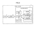
- FIG. 3 is a block diagram illustrating the robot system according to the embodiment.
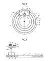
- FIG. 4 is an explanatory diagram illustrating a top view of a work bench according to a first modification of the embodiment
- FIG. 5 is an explanatory diagram illustrating a sectional view of the work bench according to the first modification of the embodiment
- FIG. 6 is an explanatory diagram illustrating a top view of a work bench according to a second modification of the embodiment
- FIG. 7 is an explanatory diagram illustrating a top view of a work bench according to a third modification of the embodiment.
- FIG. 8 is an explanatory diagram illustrating a perspective view of a work bench according to a fourth modification of the embodiment.
- FIG. 9 is an explanatory diagram illustrating a sectional view of the work bench according to the fourth modification of the embodiment.
- FIGS. 1 and 2 are explanatory diagrams illustrating top views of the robot system 1 according to the embodiment.
- the robot system 1 is provided with a robot 2 as manipulating means, a work bench 3, a robot controller 4, and a teaching device 5.
- the robot system 1 includes a robot 2 having a plurality of joints including a first joint that is provided so as to be rotatable relative to an installation surface and a means for fixing a work member such as a workpiece used in operations of the robot provided along a virtual circular arc around an axis of the first joint.
- the robot 2 is a dual-arm robot provided with a base 21, a torso 22, and two robotic arms 23.
- the base 21 is installed on a horizontal installation surface such as a floor surface.
- the torso 22 is provided so as to be rotatable about a rotation axis 20 relative to the base 21.
- the torso 22 such as described above, among components of the robot 2, serves as a part functioning as a first joint provided so as to be rotatable relative to the installation surface for the robot 2.
- the robotic arms 23 are two manipulators extending from the torso 22.
- each of the robotic arms 23 of FIG. 1 has seven degrees of freedom about rotation axes (joints) A1 to A7 as indicated each by a dashed line or black dots, and thus, the robot 2 has rotation axes at 15 places in total.
- the rotation axis 20 is perpendicular to the installation surface, and the rotation axis A1 is at a right angle with the rotation axis 20.
- the rotation axes A1 to A7 are configured such that the rotation axis A2 is at a right angle with the rotation axis A1; the rotation axis A3 is at a right angle with the rotation axis A2; the rotation axis A4 is at a right angle with the rotation axis A3; the rotation axis A5 is at a right angle with the rotation axis A4; the rotation axis A6 is at a right angle with the rotation axis A5; and the rotation axis A7 is at a right angle with the rotation axis A6.
- “being perpendicular” and “being at a right angle” need only to be substantially so for those skilled in the art, and certain degrees of errors are allowed.
- the leading ends of the robotic arms 23 such as described above are provided with end effectors 24 that can hold a workpiece to be worked and members used for work (hereinafter, the workpiece and members are mentioned as “work members 61, 62, and 63" when they are collectively called).
- the teaching device 5 is an arithmetic unit that is provided with a display unit 51, an input unit 52, and the like, and that has a function to create data (teaching data) specifying a mode of operation to be performed by the robot 2 and stores the data in the robot controller 4.
- the teaching device 5 is composed of a personal computer or a programming pendant, and the like, and is communicably connected to the robot controller 4.
- the teaching device 5 has also a function as a simulator that displays the operation of the robot 2 in a virtual manner based on the created teaching data.
- the display unit 51 is a display device that displays an image, and displays, for example, a figure modeling the robot 2 in a virtual manner.
- the input unit 52 is an information input device such as a keyboard or a touch panel. A user of the robot system 1 operates the input unit 52 such as described above to enter, into the teaching device 5, information such as teaching information including specific operations to be taught to the robot 2.
- the teaching device 5 such as described above outputs the information such as the teaching information to the robot controller 4, and thereby teaches the installation position of the work member and a predetermined operation to the robot 2.
- the robot controller 4 is a control device that controls the operation of the robot 2, and operates the robot 2 based on the information such as the teaching information received from the teaching device 5. With this control, the robot 2 performs the predetermined operation as simulated by the teaching device 5.
- the work bench 3 is at least partially provided within the working envelope of the robot 2.
- the work bench 3 has, at the center thereof, a circular opening for arranging the robot 2, and is provided with a disc-like top plate 31 with the rotation axis 20 serving as a normal line thereof.
- the upper surface of the top plate 31 is provided with a fixing part (fixture) 32 by which the work member used by the robot 2 for the work is to be fixed.
- the fixing part 32 is provided on the work bench 3 along a virtual circular arc around an axis of the first joint to fix a work member used in operations of the robot2.
- the fixing part 32 is a circular arc-like projection provided in a projecting manner in a rail-like shape along a circular arc 30 having the center at an intersection between a plate surface (the upper surface) of the top plate and the rotation axis 20.
- the work member to be fixed to the top plate 31 by the fixing part 32 is provided, on the bottom surface thereof to serve as a placing surface, with a fitting portion 60 to be fitted onto the projection that is the fixing part 32.
- the work member is a plate 6 loaded with workpieces 61, 62, and 63
- the bottom surface of the plate 6 is provided with the fitting portion 60 to be fitted onto the rail-like fixing part 32.
- the bottom surface of the plate 6 is provided with a groove-like recess, serving as the fitting portion 60, depressed to have a female shape reverse to the male shape of the fixing part 32 provided in a projecting manner in an arc-like shape. Then, the plate 6 is placed on the work bench 3 in the state in which the fitting portion 60 is fitted onto the fixing part 32.
- the robot 2 can perform the same operation as that performed before the position of the work member is changed. For example, assume that, in the state illustrated in FIG. 1 , the robot 2 is performing an operation of placing the circular workpiece 62 on top of the rectangular workpiece 61 and placing the triangular workpiece 63 on top of the circular workpiece 62.
- the plate 6 is slid (shifted) along the fixing part 32 provided in a projecting manner in an arc-like shape.
- the workpieces 61, 62, and 63 are rotated as the whole plate 6 about the rotation axis 20, as illustrated in FIG. 2 .
- the robot system 1 teaches the robot 2 the rotation angle ⁇ as a rotation angle of the torso 22 so as to rotate the torso 22 of the robot 2 by the rotation angle ⁇ .
- the robot 2 can perform, in the state illustrated in FIG. 2 , the same operation as the operation performed in the state illustrated in FIG. 1 by operating the robotic arms 23 in the same manner as taught in the state illustrated in FIG. 1 .
- the upper surface of the top plate 31 is provided with the circular arc-like fixing part 32 having the center at the intersection between the upper surface of the top plate 31 of the work bench 3 and the rotation axis 20, and the work member is moved around the rotation axis 20 along the fixing part 32.
- FIG. 3 is a block diagram illustrating the robot system 1 according to the embodiment. Note that the work bench 3, while being one of the components of the robot system 1, is omitted from the illustration here because the work bench 3 is not related to the input/output of the data.
- the robot system 1 includes the robot 2, the robot controller 4, and the teaching device 5.
- the robot 2 and the robot controller 4 will be omitted from the description here because they have already been described.
- the teaching device 5 is provided with the display unit 51, the input unit 52, a teaching unit 53, and a memory 54.
- the memory 54 stores torso rotation angle information 55 indicating the rotation angle of the torso 22 of the robot 2 relative to a predetermined position specified to the work bench 3, and also stores teaching information 56 indicating the specific operations of the two robotic arms 23 to be taught to the robot 2.
- the robot 2 As an initial state, is standing still at a predetermined initial posture face to face with the predetermined position specified to the work bench 3. Then, when making the robot 2 perform an operation, the user operates the input unit 52 to enter information such as positions of the workpieces 61, 62, and 63 and the plate 6 placed on the work bench 3, and details of operations to be performed by the robotic arms 23.
- the user further operates the input unit 52 to enter, into the teaching device 5, a rotation angle of the torso 22 of the robot 2 relative to the work bench 3.
- the input unit 52 outputs operation signals in accordance with the input operation to the teaching unit 53.
- the teaching unit 53 Based on the operation signals entered from the input unit 52, the teaching unit 53 obtains the positions of the work members (such as the workpieces 61, 62, and 63 and the plate 6) and the details of the operations to be performed by the robotic arms 23, and stores the obtained data as the teaching information 56 in the memory 54. The teaching unit 53 also obtains, based on the operation signals entered from the input unit 52, the rotation angle of the torso 22 of the robot 2, and stores the rotation angle as the torso rotation angle information 55 in the memory 54.
- the work members such as the workpieces 61, 62, and 63 and the plate 6
- the teaching unit 53 also obtains, based on the operation signals entered from the input unit 52, the rotation angle of the torso 22 of the robot 2, and stores the rotation angle as the torso rotation angle information 55 in the memory 54.
- the teaching unit 53 performs the simulation of operating the robot 2 in a virtual manner, and makes the display unit 51 display the simulation of the virtual operation of the robot 2.
- the teaching unit 53 teaches the robot 2 the specific operations by outputting the torso rotation angle information 55 and the teaching information 56 to the robot controller 4.
- the robot controller 4 Based on the torso rotation angle information 55 received from the teaching device 5, the robot controller 4 outputs a command to the robot 2 to rotate the torso 22 of the robot 2. The robot controller 4 also outputs to the robot 2, based on the teaching information 56 received from the teaching device 5, a command to operate the robotic arms 23.
- the user operates the input unit 52 to enter a rotation angle of the work member into the teaching device 5.
- the work bench 3 stores, in the memory 54, the newly entered rotation angle as the torso rotation angle information 55, and outputs the thus stored torso rotation angle information 55 to the robot controller 4.
- the robot controller 4 rotates the torso 22 of the robot 2 based on the newly entered torso rotation angle information 55, and operates the two robotic arms 23 based on the teaching information 56 used in the operation of the robot 2 before the work member is moved. With this process, the robot 2 can perform, using the work member moved on the work bench 3, the same operation as the operation being performed before the work member is moved.
- the robot system is provided with the robot that performs the operations using the robotic arms extending from the torso provided so as to be rotatable relative to the base.
- the robot system is further provided with the work bench on which the fixing part by which the work member used in the operations by the robot is fixed, is provided on the plate surface of the top plate with a rotation axis of the torso serving as a normal line thereof, along the circular arc having the center at the intersection between the plate surface and the rotation axis.
- the work member can be moved by being rotated on the work bench along the circular arc having the center at the rotation axis of the torso of the robot. Accordingly, with such a robot system, when the work member is moved on the work bench, it is possible to easily teach the robot the operation using the work member whose position is changed, only by teaching the moving (rotation) angle of the work member as the rotation angle of the torso of the robot.
- FIG. 4 is an explanatory diagram illustrating a top view of a work bench 3a according to a first modification of the embodiment
- FIG. 5 is an explanatory diagram illustrating a sectional view of the work bench 3a according to the first modification of the embodiment.
- FIG. 4 illustrates the work bench 3a viewed from the top and the state in which a plate 6a loaded with the workpieces 61, 62, and 63 is placed on the table 3a and held thereon.
- FIG. 5 illustrates a cross-section of the work bench 3a, the plate 6a, and the workpieces 61, 62, and 63 obtained by cutting along line A-A' illustrated in FIG. 4 .
- the work bench 3a is provided, on the upper surface of a top plate 31a thereof, with fixing parts (fixtures) 33, 34, and 35 by each of which a work member is to be fixed, in a recessed manner in rail-like shapes along a plurality of circular arcs having different radii from each other and having the center at an intersection between a plate surface of the top plate 31a and the rotation axis 20.
- the work bench 3a differs from the work bench 3 illustrated in FIGS. 1 and 2 in that the fixing parts 33, 34, and 35 are grooves formed not in a projecting manner but in a recessed manner, and in that the fixing parts 33, 34, and 35 are formed in shapes of concentric circles having different radii from each other. Note that the fixing parts 33, 34, and 35 are formed so as to have the same groove width as each other.
- the work member to be placed on the work bench 3a such as described above is provided, on the bottom surface thereof to serve as a placing surface, with a fitting portion 60a to be fitted into the fixing parts 33, 34, and 35.
- the work member is the plate 6a
- the bottom surface of the plate 6a is provided, in a projecting manner, with the prism-like fitting portion 60a that is fittable into each of the fixing parts 33, 34, and 35.
- the plate 6a that is loaded with the workpieces 61, 62, and 63 and to be placed on the work bench 3a is fixed in such a manner that the fitting portion 60a on the bottom surface of the plate 6a is fitted into any one of the fixing parts 33, 34, and 35 provided on the upper surface of the work bench 3a.
- the work member can be moved on the work bench 3a along the circular arc having the center at the intersection between the plate surface of the top plate 31a and the rotation axis 20.
- the distance between the robot 2 and the work member can be changed by changing the fixing part to be fitted with the fitting portion 60a among the fixing parts 33, 34, and 35, without moving the work member along the circular arc having the center at the rotation axis 20.
- the teaching information 56 after such a change can be used without change in the case of moving the work member along the fixing part 33, 34, or 35 for fixing the work member, unless the fixing part 33, 34, or 35 is changed.
- FIG. 6 is an explanatory diagram illustrating a top view of the work bench 3b according to the second modification of the embodiment.
- the work bench 3b is provided, on the upper surface of a top plate 31b thereof, with a plurality of fixing parts (fixtures) 36 in a recessed manner at predetermined distance intervals along a plurality of circular arcs (refer to circles indicated by dashed lines in FIG. 6 ) having different radii from each other and having the center at an intersection between a plate surface of the top plate 31b and the rotation axis 20.
- the angle formed between the front as viewed from the robot 2 standing still in the above-described initial state (hereinafter mentioned as “front direction”) and the direction from the rotation axis 20 toward each of the fixing parts 36 (hereinafter mentioned as “fixing part direction”) is a predetermined angle.
- a work member provided, on the bottom surface thereof, with the fitting portion 60a in a projecting manner is placed on the work bench 3b. More specifically, the work member is placed on the work bench 3b in the state in which the fitting portion 60a provided in a projecting manner on the bottom surface is fitted into one of the fixing parts 36.
- the angle formed between the front direction and the fixing part direction of each of the fixing parts 36 used for fixing the work member is known. Therefore, on the work bench 3b, when the work member is moved along one of the concentric circles indicated by dashed lines in FIG. 6 , it is possible to make the robot 2 perform the same operation as that performed before the movement of the work member, only by teaching the angle formed between the fixing part direction of the fixing part 36 used for fixing the work member and the front direction.
- FIG. 7 is an explanatory diagram illustrating a top view of the work bench 3c according to the third modification of the embodiment.
- the work bench 3c is provided, on the upper surface of a top plate 31c thereof, with line-like fixing parts (fixture) 37 in a projecting manner along straight lines (refer to straight lines indicated by dashed lines in FIG. 7 ) radially extending on a plate surface of the top plate 31c from the intersection between the plate surface of the top plate 31c and the rotation axis 20.
- line-like fixing parts (fixture) 37 in a projecting manner along straight lines (refer to straight lines indicated by dashed lines in FIG. 7 ) radially extending on a plate surface of the top plate 31c from the intersection between the plate surface of the top plate 31c and the rotation axis 20.
- fixing part direction On the plate surface of the top plate 31c, the angle formed between the front direction as viewed from the robot 2 standing still in the above-described initial state and the direction from the rotation axis 20 toward each of the fixing parts 37 (hereinafter mentioned as "fixing part direction”) is a predetermined angle.
- a work member to be fixed to the top plate 31c by one of the fixing parts 37 is provided, on the bottom surface thereof to serve as a placing surface, with a fitting portion 60c to be fitted onto the line-like projection that is the fixing part 37.
- the work member is a plate 6c loaded with the workpieces 61, 62, and 63
- the bottom surface of the plate 6c is provided with the fitting portion 60c to be fitted onto the rail-like fixing part 37.
- the bottom surface of the plate 6c is provided with a groove-like recess, serving as the fitting portion 60c, depressed to have a female shape reverse to the male shape of the fixing part 37 provided in a projecting manner in a line-like shape.
- the angle formed between the fixing part direction of each of the fixing parts 37 used for fixing the work member and the above-described front direction is known. Therefore, on the work bench 3c, when the work member is moved around the rotation axis 20 on the top plate 31c, it is possible to make the robot 2 perform the same operation as that performed before the movement of the work member, only by teaching the angle formed between the fixing part direction of the fixing part 37 used for fixing the work member and the front direction.
- fixing parts 37 have a linear projection-like shape as viewed from the top
- fixing parts having a linear recess-like shape as viewed from the top may be provided instead of the fixing parts 37.
- fixing parts it is possible to fix, to the work bench, the work member provided, on the bottom thereof, with the fitting portion 60a in a projecting manner like the plate 6a illustrated in FIG. 4 .
- the fixing parts 33, 34, and 35 having a circular recess-like shape as viewed from the top illustrated in FIG. 4 may be provided in addition to such radially extending fixing parts.
- the bottom surface of the work member may be provided with a fitting portion having a cross-like shape as viewed from the bottom that is fittable into an intersecting portion between the fixing part having a linear recess-like shape as viewed from the top and the fixing part having a circular recess-like shape as viewed from the top.
- FIG. 8 is an explanatory diagram illustrating a perspective view of the work bench 3d according to the fourth modification of the embodiment
- FIG. 9 is an explanatory diagram illustrating a sectional view of the work bench 3d according to the fourth modification of the embodiment.
- FIG. 9 illustrates a cross-section of the work bench 3d obtained by cutting along line B-B' illustrated in FIG. 8 .
- the work bench 3d is provided with a top plate 31 including a fixing part 32 having the same shape as that illustrated in FIGS. 1 and 2 , and with a leg 38 supporting the top plate 31 from below.
- the leg 38 has a closed-end cylindrical shape, and supports the top plate 31 in the state in which an open end at the top is connected to an opening provided at the center of the top plate 31.
- the leg 38 is provided, at the central part of the bottom surface thereof, with a hole 39 for fixing the robot 2.
- the robot 2 that performs operation using the work bench 3d such as described above is provided, at the central part of the bottom surface of the base 21 through which the rotation axis 20 passes, with a fitting portion 25 fittable into the hole 39 in a projecting manner, and is installed in a state in which the fitting portion 25 is fitted into the hole 39.
- the opening at the center of the top plate may have any shape, such as an ellipse, a rectangle, and a polygon.
- the top plate is not limited to having a circular shape, but may have any shape.
- the robot need not have any base or torso, but may be configured to be directly installed as a single manipulator on the installation surface.
- the first joint provided so as to be rotatable relative to the installation surface is directly installed onto the installation surface.
- the axis configuration of the robot is not limited to the above-described embodiment, but the robot may have a parallel link mechanism and may have six or fewer degrees of freedom.
- a teaching method includes: teaching a robot an operation of the robot having a plurality of joints including a first joint that is provided so as to be rotatable relative to an installation surface; and teaching the robot a shift amount to change a rotation angle of the first joint according to a position of a fixing part for fixing a work member used in the operation provided along a virtual circular arc around an axis of the first joint.
- a teaching method includes: a step for teaching a robot an operation of the robot having a plurality of joints including a first joint that is provided so as to be rotatable relative to an installation surface; and a step for teaching the robot a shift amount to change a rotation angle of the first joint according to a position of a fixing part for fixing a work member used in the operation provided along a virtual circular arc around an axis of the first joint.
Landscapes
- Engineering & Computer Science (AREA)
- Robotics (AREA)
- Mechanical Engineering (AREA)
- Manipulator (AREA)
- Numerical Control (AREA)
Abstract
Description
- The embodiment discussed herein is directed to a robot system and a teaching method therefor.
- Japanese Patent Application Laid-open No.
2011-240443 - Generally, in such a robot system, the positions of the work members arranged on the work bench are taught to the robot in advance. With this teaching, the robot can perform the work using the work members arranged on the work bench.
- In the robot system, if a position of a work member on the work bench is changed, it is possible to operate the robot by shifting the original operating position by an amount of the change in the position. However, such shifting of the operation can provide insufficient positional accuracy, or cause problems such as necessity to avoid an overload to an actuator constituting the robot or to avoid a singular point of control.
- There has been a problem that, in such a case, the robot needs to be taught again an operation using the work member whose position is changed, and that such a teaching operation is complicated.
- In view of the description made above, it is an object of an aspect of the embodiment to provide a robot system and a teaching method therefor that, when a position of a work member on the work bench is changed, can easily teach a robot an operation using the work member whose position is changed.
- A robot system according to an aspect of the embodiment is provided with a robot, a work bench, and a fixing part. The robot has a plurality of joints including a first joint that is provided so as to be rotatable relative to an installation surface. The work bench is provided in a working envelope of the robot. The fixing part is provided on the work bench along a virtual circular arc around an axis of the first joint to fix a work member used in operations of the robot.
- With the robot system according to the aspect of the embodiment, it is possible to easily teach the robot, when a position of a work member on the work bench is changed, an operation using the work member whose position is changed.
- A more complete appreciation of the invention and many of the attendant advantages thereof will be readily obtained as the same becomes better understood by reference to the following detailed description when considered in connection with the accompanying drawings, wherein:
-
FIGS. 1 and 2 are explanatory diagrams illustrating top views of a robot system according to the embodiment; -
FIG. 3 is a block diagram illustrating the robot system according to the embodiment; -
FIG. 4 is an explanatory diagram illustrating a top view of a work bench according to a first modification of the embodiment; -
FIG. 5 is an explanatory diagram illustrating a sectional view of the work bench according to the first modification of the embodiment; -
FIG. 6 is an explanatory diagram illustrating a top view of a work bench according to a second modification of the embodiment; -
FIG. 7 is an explanatory diagram illustrating a top view of a work bench according to a third modification of the embodiment; -
FIG. 8 is an explanatory diagram illustrating a perspective view of a work bench according to a fourth modification of the embodiment; and -
FIG. 9 is an explanatory diagram illustrating a sectional view of the work bench according to the fourth modification of the embodiment. - An embodiment of a robot system and a teaching method therefor disclosed herein will be described below in detail with reference to the accompanying drawings. Note that the embodiment is not limited to the embodiment illustrated below.
-
FIGS. 1 and 2 are explanatory diagrams illustrating top views of the robot system 1 according to the embodiment. As illustrated inFIG. 1 , the robot system 1 is provided with arobot 2 as manipulating means, awork bench 3, a robot controller 4, and ateaching device 5. Herein, the robot system 1 includes arobot 2 having a plurality of joints including a first joint that is provided so as to be rotatable relative to an installation surface and a means for fixing a work member such as a workpiece used in operations of the robot provided along a virtual circular arc around an axis of the first joint. - The
robot 2 is a dual-arm robot provided with abase 21, atorso 22, and tworobotic arms 23. Here, thebase 21 is installed on a horizontal installation surface such as a floor surface. Thetorso 22 is provided so as to be rotatable about arotation axis 20 relative to thebase 21. In other words, in the present embodiment, thetorso 22 such as described above, among components of therobot 2, serves as a part functioning as a first joint provided so as to be rotatable relative to the installation surface for therobot 2. - The
robotic arms 23 are two manipulators extending from thetorso 22. In the present embodiment, for example, each of therobotic arms 23 ofFIG. 1 has seven degrees of freedom about rotation axes (joints) A1 to A7 as indicated each by a dashed line or black dots, and thus, therobot 2 has rotation axes at 15 places in total. - In the present embodiment, the
rotation axis 20 is perpendicular to the installation surface, and the rotation axis A1 is at a right angle with therotation axis 20. The rotation axes A1 to A7 are configured such that the rotation axis A2 is at a right angle with the rotation axis A1; the rotation axis A3 is at a right angle with the rotation axis A2; the rotation axis A4 is at a right angle with the rotation axis A3; the rotation axis A5 is at a right angle with the rotation axis A4; the rotation axis A6 is at a right angle with the rotation axis A5; and the rotation axis A7 is at a right angle with the rotation axis A6. Note that "being perpendicular" and "being at a right angle" need only to be substantially so for those skilled in the art, and certain degrees of errors are allowed. - The leading ends of the
robotic arms 23 such as described above are provided withend effectors 24 that can hold a workpiece to be worked and members used for work (hereinafter, the workpiece and members are mentioned as "work members - The
teaching device 5 is an arithmetic unit that is provided with adisplay unit 51, aninput unit 52, and the like, and that has a function to create data (teaching data) specifying a mode of operation to be performed by therobot 2 and stores the data in the robot controller 4. Theteaching device 5 is composed of a personal computer or a programming pendant, and the like, and is communicably connected to the robot controller 4. In the present embodiment, theteaching device 5 has also a function as a simulator that displays the operation of therobot 2 in a virtual manner based on the created teaching data. - The
display unit 51 is a display device that displays an image, and displays, for example, a figure modeling therobot 2 in a virtual manner. Theinput unit 52 is an information input device such as a keyboard or a touch panel. A user of the robot system 1 operates theinput unit 52 such as described above to enter, into theteaching device 5, information such as teaching information including specific operations to be taught to therobot 2. - The
teaching device 5 such as described above outputs the information such as the teaching information to the robot controller 4, and thereby teaches the installation position of the work member and a predetermined operation to therobot 2. The robot controller 4 is a control device that controls the operation of therobot 2, and operates therobot 2 based on the information such as the teaching information received from theteaching device 5. With this control, therobot 2 performs the predetermined operation as simulated by theteaching device 5. - The
work bench 3 is at least partially provided within the working envelope of therobot 2. Thework bench 3 has, at the center thereof, a circular opening for arranging therobot 2, and is provided with a disc-liketop plate 31 with therotation axis 20 serving as a normal line thereof. The upper surface of thetop plate 31 is provided with a fixing part (fixture) 32 by which the work member used by therobot 2 for the work is to be fixed. Thefixing part 32 is provided on thework bench 3 along a virtual circular arc around an axis of the first joint to fix a work member used in operations of the robot2. Thefixing part 32 is a circular arc-like projection provided in a projecting manner in a rail-like shape along acircular arc 30 having the center at an intersection between a plate surface (the upper surface) of the top plate and therotation axis 20. - The work member to be fixed to the
top plate 31 by thefixing part 32 is provided, on the bottom surface thereof to serve as a placing surface, with a fitting portion 60 to be fitted onto the projection that is thefixing part 32. For example, as illustrated inFIG. 1 , if the work member is aplate 6 loaded withworkpieces plate 6 is provided with the fitting portion 60 to be fitted onto the rail-like fixing part 32. - More specifically, the bottom surface of the
plate 6 is provided with a groove-like recess, serving as the fitting portion 60, depressed to have a female shape reverse to the male shape of thefixing part 32 provided in a projecting manner in an arc-like shape. Then, theplate 6 is placed on thework bench 3 in the state in which the fitting portion 60 is fitted onto thefixing part 32. - In the robot system 1 such as described above, after the position of the work member is changed on the
work bench 3, therobot 2 can perform the same operation as that performed before the position of the work member is changed. For example, assume that, in the state illustrated inFIG. 1 , therobot 2 is performing an operation of placing thecircular workpiece 62 on top of therectangular workpiece 61 and placing thetriangular workpiece 63 on top of thecircular workpiece 62. - Then, in the case of changing the positions of the
workpieces work bench 3, theplate 6 is slid (shifted) along thefixing part 32 provided in a projecting manner in an arc-like shape. For example, in the case of changing the positions of theworkpieces robot 2 in the state illustrated inFIG. 1 , theworkpieces whole plate 6 about therotation axis 20, as illustrated inFIG. 2 . - At this time, if the
plate 6 is rotated about therotation axis 20 by a rotation angle 8, the robot system 1 teaches therobot 2 the rotation angle θ as a rotation angle of thetorso 22 so as to rotate thetorso 22 of therobot 2 by the rotation angle θ. - With this operation, as illustrated in
FIG. 2 , the relative positions of theworkpieces robot 2 become the same as the relative positions illustrated inFIG. 1 . Accordingly, therobot 2 can perform, in the state illustrated inFIG. 2 , the same operation as the operation performed in the state illustrated inFIG. 1 by operating therobotic arms 23 in the same manner as taught in the state illustrated inFIG. 1 . - In this manner, in the robot system 1, the upper surface of the
top plate 31 is provided with the circular arc-like fixingpart 32 having the center at the intersection between the upper surface of thetop plate 31 of thework bench 3 and therotation axis 20, and the work member is moved around therotation axis 20 along the fixingpart 32. - With this arrangement, in the robot system 1, when the work member is moved, it is possible to easily teach the
robot 2 the operation to be performed using the work member whose position is changed, only by teaching therobot 2 the rotation angle of the work member rotated about therotation axis 20. - Next, description will be made of input and output of various types of data performed in the robot system 1.
FIG. 3 is a block diagram illustrating the robot system 1 according to the embodiment. Note that thework bench 3, while being one of the components of the robot system 1, is omitted from the illustration here because thework bench 3 is not related to the input/output of the data. - As illustrated in
FIG. 3 , the robot system 1 includes therobot 2, the robot controller 4, and theteaching device 5. Therobot 2 and the robot controller 4 will be omitted from the description here because they have already been described. - The
teaching device 5 is provided with thedisplay unit 51, theinput unit 52, ateaching unit 53, and amemory 54. Thememory 54 stores torsorotation angle information 55 indicating the rotation angle of thetorso 22 of therobot 2 relative to a predetermined position specified to thework bench 3, and alsostores teaching information 56 indicating the specific operations of the tworobotic arms 23 to be taught to therobot 2. - In the robot system such as described above, the
robot 2, as an initial state, is standing still at a predetermined initial posture face to face with the predetermined position specified to thework bench 3. Then, when making therobot 2 perform an operation, the user operates theinput unit 52 to enter information such as positions of theworkpieces plate 6 placed on thework bench 3, and details of operations to be performed by therobotic arms 23. - The user further operates the
input unit 52 to enter, into theteaching device 5, a rotation angle of thetorso 22 of therobot 2 relative to thework bench 3. Theinput unit 52 outputs operation signals in accordance with the input operation to theteaching unit 53. - Based on the operation signals entered from the
input unit 52, theteaching unit 53 obtains the positions of the work members (such as theworkpieces robotic arms 23, and stores the obtained data as the teachinginformation 56 in thememory 54. Theteaching unit 53 also obtains, based on the operation signals entered from theinput unit 52, the rotation angle of thetorso 22 of therobot 2, and stores the rotation angle as the torsorotation angle information 55 in thememory 54. - Furthermore, based on the torso
rotation angle information 55 and theteaching information 56 stored in thememory 54, theteaching unit 53 performs the simulation of operating therobot 2 in a virtual manner, and makes thedisplay unit 51 display the simulation of the virtual operation of therobot 2. - Then, if the simulation confirms that the
robot 2 will operate without any problem, theteaching unit 53 teaches therobot 2 the specific operations by outputting the torsorotation angle information 55 and theteaching information 56 to the robot controller 4. - Based on the torso
rotation angle information 55 received from theteaching device 5, the robot controller 4 outputs a command to therobot 2 to rotate thetorso 22 of therobot 2. The robot controller 4 also outputs to therobot 2, based on theteaching information 56 received from theteaching device 5, a command to operate therobotic arms 23. - Thereafter, in the case of moving the work member by rotating it about the
rotation axis 20 along the circular arc-like fixingpart 32, the user operates theinput unit 52 to enter a rotation angle of the work member into theteaching device 5. In theteaching device 5, thework bench 3 stores, in thememory 54, the newly entered rotation angle as the torsorotation angle information 55, and outputs the thus stored torsorotation angle information 55 to the robot controller 4. - The robot controller 4 rotates the
torso 22 of therobot 2 based on the newly entered torsorotation angle information 55, and operates the tworobotic arms 23 based on theteaching information 56 used in the operation of therobot 2 before the work member is moved. With this process, therobot 2 can perform, using the work member moved on thework bench 3, the same operation as the operation being performed before the work member is moved. - As described above, the robot system according to the embodiment is provided with the robot that performs the operations using the robotic arms extending from the torso provided so as to be rotatable relative to the base. The robot system is further provided with the work bench on which the fixing part by which the work member used in the operations by the robot is fixed, is provided on the plate surface of the top plate with a rotation axis of the torso serving as a normal line thereof, along the circular arc having the center at the intersection between the plate surface and the rotation axis.
- In the robot system as described above, the work member can be moved by being rotated on the work bench along the circular arc having the center at the rotation axis of the torso of the robot. Accordingly, with such a robot system, when the work member is moved on the work bench, it is possible to easily teach the robot the operation using the work member whose position is changed, only by teaching the moving (rotation) angle of the work member as the rotation angle of the torso of the robot.
- Note that the work bench according to the present embodiment is not limited to the
work bench 3 illustrated inFIGS. 1 and 2 . Modifications of the work bench according to the present embodiment will be described below.FIG. 4 is an explanatory diagram illustrating a top view of awork bench 3a according to a first modification of the embodiment, andFIG. 5 is an explanatory diagram illustrating a sectional view of thework bench 3a according to the first modification of the embodiment. - Here,
FIG. 4 , illustrates thework bench 3a viewed from the top and the state in which aplate 6a loaded with theworkpieces FIG. 5 illustrates a cross-section of thework bench 3a, theplate 6a, and theworkpieces FIG. 4 . - Here, among the components illustrated in
FIGS. 4 and 5 , the same components as those illustrated inFIG, 1 or 2 are given the same numerals as those of the components illustrated inFIG, 1 or 2 , and thereby description thereof will be omitted. - As illustrated in
FIGS. 4 and 5 , thework bench 3a is provided, on the upper surface of atop plate 31a thereof, with fixing parts (fixtures) 33, 34, and 35 by each of which a work member is to be fixed, in a recessed manner in rail-like shapes along a plurality of circular arcs having different radii from each other and having the center at an intersection between a plate surface of thetop plate 31a and therotation axis 20. - Specifically, the
work bench 3a differs from thework bench 3 illustrated inFIGS. 1 and 2 in that the fixingparts parts parts - The work member to be placed on the
work bench 3a such as described above is provided, on the bottom surface thereof to serve as a placing surface, with afitting portion 60a to be fitted into the fixingparts plate 6a, the bottom surface of theplate 6a is provided, in a projecting manner, with the prism-likefitting portion 60a that is fittable into each of the fixingparts - Then, as illustrated in
FIG. 5 , theplate 6a that is loaded with theworkpieces work bench 3a is fixed in such a manner that thefitting portion 60a on the bottom surface of theplate 6a is fitted into any one of the fixingparts work bench 3a. - Thus, also in the case in which the
work bench 3a is provided with the fixingparts fitting portion 60a in a recessed manner, the work member can be moved on thework bench 3a along the circular arc having the center at the intersection between the plate surface of thetop plate 31a and therotation axis 20. - Therefore, also with the
work bench 3a such as described above, when the work member is moved on thework bench 3a, it is possible to easily teach therobot 2 the operation performed using the work member, only by teaching the moving (rotation) angle of the work member as the rotation angle of thetorso 22 of therobot 2. - In addition, with the
work bench 3a, the distance between therobot 2 and the work member can be changed by changing the fixing part to be fitted with thefitting portion 60a among the fixingparts rotation axis 20. - In the case of changing the distance between the
robot 2 and the work member in this manner, it is necessary to change theteaching information 56. However, such a change is not a large change compared with a change in theteaching information 56 in the case of moving the work member in the right-left direction when viewed from therobot 2 without rotating thetorso 22 of therobot 2. - Once being stored in the
memory 54, the teachinginformation 56 after such a change can be used without change in the case of moving the work member along the fixingpart part - Next, a
work bench 3b according to a second modification will be described with reference toFIG. 6. FIG. 6 is an explanatory diagram illustrating a top view of thework bench 3b according to the second modification of the embodiment. As illustrated inFIG. 6 , thework bench 3b is provided, on the upper surface of atop plate 31b thereof, with a plurality of fixing parts (fixtures) 36 in a recessed manner at predetermined distance intervals along a plurality of circular arcs (refer to circles indicated by dashed lines inFIG. 6 ) having different radii from each other and having the center at an intersection between a plate surface of thetop plate 31b and therotation axis 20. - On the plate surface of the
top plate 31b, the angle formed between the front as viewed from therobot 2 standing still in the above-described initial state (hereinafter mentioned as "front direction") and the direction from therotation axis 20 toward each of the fixing parts 36 (hereinafter mentioned as "fixing part direction") is a predetermined angle. - Then, like, for example, the
plate 6a illustrated inFIG. 5 , a work member provided, on the bottom surface thereof, with thefitting portion 60a in a projecting manner is placed on thework bench 3b. More specifically, the work member is placed on thework bench 3b in the state in which thefitting portion 60a provided in a projecting manner on the bottom surface is fitted into one of the fixingparts 36. - On the
work bench 3b such as described above, the angle formed between the front direction and the fixing part direction of each of the fixingparts 36 used for fixing the work member is known. Therefore, on thework bench 3b, when the work member is moved along one of the concentric circles indicated by dashed lines inFIG. 6 , it is possible to make therobot 2 perform the same operation as that performed before the movement of the work member, only by teaching the angle formed between the fixing part direction of the fixingpart 36 used for fixing the work member and the front direction. - While the case has been described here in which the fixing
parts 36 are provided in a recessed manner, projecting fixing parts may be provided instead of the fixingparts 36 provided in a recessed manner. In such a case, the bottom of the work member is provided with a recess that is fittable, as a fitting portion, onto each of the fixing parts provided in a projecting manner. - Next, a
work bench 3c according to a third modification will be described with reference toFIG. 7. FIG. 7 is an explanatory diagram illustrating a top view of thework bench 3c according to the third modification of the embodiment. As illustrated inFIG. 7 , thework bench 3c is provided, on the upper surface of atop plate 31c thereof, with line-like fixing parts (fixture) 37 in a projecting manner along straight lines (refer to straight lines indicated by dashed lines inFIG. 7 ) radially extending on a plate surface of thetop plate 31c from the intersection between the plate surface of thetop plate 31c and therotation axis 20. - On the plate surface of the
top plate 31c, the angle formed between the front direction as viewed from therobot 2 standing still in the above-described initial state and the direction from therotation axis 20 toward each of the fixing parts 37 (hereinafter mentioned as "fixing part direction") is a predetermined angle. - A work member to be fixed to the
top plate 31c by one of the fixingparts 37 is provided, on the bottom surface thereof to serve as a placing surface, with afitting portion 60c to be fitted onto the line-like projection that is the fixingpart 37. For example, as illustrated onFIG. 7 , if the work member is aplate 6c loaded with theworkpieces plate 6c is provided with thefitting portion 60c to be fitted onto the rail-like fixingpart 37. More specifically, the bottom surface of theplate 6c is provided with a groove-like recess, serving as thefitting portion 60c, depressed to have a female shape reverse to the male shape of the fixingpart 37 provided in a projecting manner in a line-like shape. - On the
work bench 3c such as described above, the angle formed between the fixing part direction of each of the fixingparts 37 used for fixing the work member and the above-described front direction is known. Therefore, on thework bench 3c, when the work member is moved around therotation axis 20 on thetop plate 31c, it is possible to make therobot 2 perform the same operation as that performed before the movement of the work member, only by teaching the angle formed between the fixing part direction of the fixingpart 37 used for fixing the work member and the front direction. - In addition, with the
work bench 3c, it is possible, by moving the work member toward the extending direction of the fixingpart 37, to easily adjust the distance between therobot 2 and the work member while maintaining the angle formed between the fixing part direction of the fixingpart 37 used for fixing the work member and the front direction. - While the case has been described here in which the fixing
parts 37 have a linear projection-like shape as viewed from the top, fixing parts having a linear recess-like shape as viewed from the top may be provided instead of the fixingparts 37. With such fixing parts, it is possible to fix, to the work bench, the work member provided, on the bottom thereof, with thefitting portion 60a in a projecting manner like theplate 6a illustrated inFIG. 4 . - In the case in which the
top plate 31c is provided, on the plate surface thereof, with the fixing parts that have a linear recess-like shape as viewed from the top and extends radially from therotation axis 20, the fixingparts FIG. 4 may be provided in addition to such radially extending fixing parts. - In such a case, the bottom surface of the work member may be provided with a fitting portion having a cross-like shape as viewed from the bottom that is fittable into an intersecting portion between the fixing part having a linear recess-like shape as viewed from the top and the fixing part having a circular recess-like shape as viewed from the top. By employing such a configuration, it is possible, by fitting the fitting portion of the work member into the intersecting portion between the fixing part having a linear recess-like shape as viewed from the top and the fixing part having a circular recess-like shape as viewed from the top, to ensure to prevent a fixing position to which the work member is once fixed from changing during the operation of the
robot 2. - Next, a
work bench 3d according to a fourth modification will be described with reference toFIGS. 8 and 9. FIG. 8 is an explanatory diagram illustrating a perspective view of thework bench 3d according to the fourth modification of the embodiment, andFIG. 9 is an explanatory diagram illustrating a sectional view of thework bench 3d according to the fourth modification of the embodiment.FIG. 9 illustrates a cross-section of thework bench 3d obtained by cutting along line B-B' illustrated inFIG. 8 . - As illustrated in
FIG. 8 , thework bench 3d is provided with atop plate 31 including a fixingpart 32 having the same shape as that illustrated inFIGS. 1 and 2 , and with aleg 38 supporting thetop plate 31 from below. Theleg 38 has a closed-end cylindrical shape, and supports thetop plate 31 in the state in which an open end at the top is connected to an opening provided at the center of thetop plate 31. In addition, theleg 38 is provided, at the central part of the bottom surface thereof, with ahole 39 for fixing therobot 2. - As illustrated in
FIG. 9 , therobot 2 that performs operation using thework bench 3d such as described above is provided, at the central part of the bottom surface of the base 21 through which therotation axis 20 passes, with afitting portion 25 fittable into thehole 39 in a projecting manner, and is installed in a state in which thefitting portion 25 is fitted into thehole 39. - With this arrangement, it is possible to perform position adjustment between the center of the fixing
part 32 that has a circular shape as viewed from the top and is provided on the upper surface of thetop plate 31 in an easy and accurate manner, only by fitting thefitting portion 25 provided on the bottom surface of thebase 21 of therobot 2 into thehole 39. - While, in the embodiment given above, the case has been described in which the circular opening is provided at the center of the top plate of the work bench, the opening at the center of the top plate may have any shape, such as an ellipse, a rectangle, and a polygon. Also, the top plate is not limited to having a circular shape, but may have any shape.
- Furthermore, while, in the embodiment given above, the description has been made of the example of the dual-arm robot having the base 21 and the
torso 22, the robot need not have any base or torso, but may be configured to be directly installed as a single manipulator on the installation surface. In the case of such a configuration, among the components of the manipulator, the first joint provided so as to be rotatable relative to the installation surface is directly installed onto the installation surface. Also, the axis configuration of the robot is not limited to the above-described embodiment, but the robot may have a parallel link mechanism and may have six or fewer degrees of freedom. - A teaching method according to the embodiment includes: teaching a robot an operation of the robot having a plurality of joints including a first joint that is provided so as to be rotatable relative to an installation surface; and teaching the robot a shift amount to change a rotation angle of the first joint according to a position of a fixing part for fixing a work member used in the operation provided along a virtual circular arc around an axis of the first joint.
- Moreover, a teaching method according to the embodiment includes: a step for teaching a robot an operation of the robot having a plurality of joints including a first joint that is provided so as to be rotatable relative to an installation surface; and a step for teaching the robot a shift amount to change a rotation angle of the first joint according to a position of a fixing part for fixing a work member used in the operation provided along a virtual circular arc around an axis of the first joint.
Claims (10)
- A robot system (1) charactorized by comprising:a robot (2) having a plurality of joints including a first joint (22) that is provided so as to be rotatable relative to an installation surface; anda work bench (3, 3a, 3b, 3c, or 3d) provided in a working envelope of the robot; anda fixing part (32, 33, 34, 35, 36, 37) provided on the work bench along a virtual circular arc (30) around an axis (20) of the first joint (22) to fix a work member used in operations of the robot (2).
- The robot system (1) according to claim 1, wherein
the first joint (22) is a torso (22) that is provided so as to be rotatable relative to a base (21) installed on the installation surface; and
the robot (2) comprises a robotic arm (23) that is mounted on the torso (22) and that has a plurality of joints. - The robot system (1) according to claim 1 or 2, wherein the fixing part (33, 34, 35, 36) is provided along a plurality of such circular arcs having different radii from each other.
- The robot system (1) according to any one of claims 1 to 3, wherein the fixing part (36, 37) is provided at predetermined distance intervals along the circular arc(s).
- The robot system (1) according to any one of claims 1 to 4, wherein the work member is provided with a fitting portion (60, 60a, or 60c) that is fitted to the fixing part (32, 33, 34, 35, 36, or 37).
- The robot system (1) according to any one of claims 1 to 5, wherein the work bench (3c) is provided with the fixing part (37) by which the work member is fixed along straight lines radially extending from the center of the virtual circular arc.
- The robot system (1) according to any one of claims 1 to 6, further comprising:an input unit (52) that enters teaching information (56) indicating specific operations to be taught to the robot (2) and also enters rotation angle information (55) indicating a rotation angle of the first joint (22);a memory (54) that stores the teaching information (56) and the rotation angle information (55) entered by the input unit (52); anda teaching unit (53) that teaches the robot (2) the rotation angle of the first joint (22) based on the rotation angle information (55) stored in the memory (54), and also teaches the robot (2) the specific operations based on the teaching information (56) stored in the memory (54).
- A robot system comprising:a manipulating means (2) including a joint (22) that is provided so as to be rotatable relative to an installation surface; anda means for fixing a work member used in operations of the manipulating means along a virtual circular arc around an axis (20) of the joint (22).
- A teaching method comprising:teaching a robot (2) an operation of the robot having a plurality of joints including a first joint (22) that is provided so as to be rotatable relative to an installation surface; andteaching the robot (2) a shift amount to change a rotation angle of the first joint according to a position of a fixing part (32, 33, 34, 35, 36, 37) for fixing a work member used in the operation provided along a virtual circular arc around an axis (20) of the first joint (22).
- A teaching method comprising:a step for teaching a robot an operation of the robot having a plurality of joints including a first joint (22) that is provided so as to be rotatable relative to an installation surface; anda step for teaching the robot a shift amount to change a rotation angle of the first joint (22) according to a position of a fixing part (32, 33, 34, 35, 36, 37) for fixing a work member used in the operation provided along a virtual circular arc around an axis (20) of the first joint (22).
Applications Claiming Priority (1)
| Application Number | Priority Date | Filing Date | Title |
|---|---|---|---|
| JP2012192352A JP5549716B2 (en) | 2012-08-31 | 2012-08-31 | Robot system and teaching method |
Publications (2)
| Publication Number | Publication Date |
|---|---|
| EP2712714A2 true EP2712714A2 (en) | 2014-04-02 |
| EP2712714A3 EP2712714A3 (en) | 2015-11-04 |
Family
ID=47900569
Family Applications (1)
| Application Number | Title | Priority Date | Filing Date |
|---|---|---|---|
| EP13156801.6A Withdrawn EP2712714A3 (en) | 2012-08-31 | 2013-02-26 | Robot system and teaching method therefor |
Country Status (4)
| Country | Link |
|---|---|
| US (1) | US9067316B2 (en) |
| EP (1) | EP2712714A3 (en) |
| JP (1) | JP5549716B2 (en) |
| CN (1) | CN103659795A (en) |
Families Citing this family (8)
| Publication number | Priority date | Publication date | Assignee | Title |
|---|---|---|---|---|
| JP6355716B2 (en) * | 2013-04-09 | 2018-07-11 | カルロ・フィリッポ・ラッティ | Interactive robot station for the preparation and distribution of beverages, especially cocktails |
| JP2015186235A (en) | 2014-03-26 | 2015-10-22 | ソニー株式会社 | Image sensor and electronic device |
| JP5682721B1 (en) | 2014-03-31 | 2015-03-11 | ソニー株式会社 | Industrial robot and its mounting unit |
| CN106355989B (en) * | 2016-10-21 | 2022-07-08 | 江苏哈工海渡教育科技集团有限公司 | Industrial robot mounting base plate with interchangeable mounting positions |
| CN106297526A (en) * | 2016-10-21 | 2017-01-04 | 苏州哈工海渡工业机器人有限公司 | A kind of modularity six-joint robot comprehensive practical traning platform |
| JP7446925B2 (en) * | 2020-06-04 | 2024-03-11 | 芝浦機械株式会社 | robot system |
| CN114905520B (en) * | 2022-06-28 | 2023-11-24 | 中国华能集团清洁能源技术研究院有限公司 | Safety limit method, device, equipment and storage medium for double-arm cooperative robot |
| US20240273496A1 (en) * | 2023-02-14 | 2024-08-15 | Minga Box Ltd. | Interactive bartender |
Citations (1)
| Publication number | Priority date | Publication date | Assignee | Title |
|---|---|---|---|---|
| JP2011240443A (en) | 2010-05-19 | 2011-12-01 | Canon Inc | Robot cell apparatus, and production system |
Family Cites Families (18)
| Publication number | Priority date | Publication date | Assignee | Title |
|---|---|---|---|---|
| CH655039A5 (en) * | 1981-07-09 | 1986-03-27 | Zumbach Ag R | Assembly method by means of a robot, and robot for carrying out this method |
| JPH01240239A (en) * | 1988-03-22 | 1989-09-25 | Honda Motor Co Ltd | Assembly line |
| JPH0445664U (en) * | 1990-08-24 | 1992-04-17 | ||
| JP3282696B2 (en) * | 1993-11-24 | 2002-05-20 | 株式会社安川電機 | Work equipment |
| JP2722379B2 (en) * | 1995-06-15 | 1998-03-04 | 日本高周波鋼業株式会社 | Workpiece holder |
| JP3798495B2 (en) * | 1997-02-17 | 2006-07-19 | 株式会社諏訪機械製作所 | Work mounting jig |
| JP3170627B2 (en) * | 1999-06-23 | 2001-05-28 | 信和興産株式会社 | Welding method and welding equipment |
| US6681151B1 (en) * | 2000-12-15 | 2004-01-20 | Cognex Technology And Investment Corporation | System and method for servoing robots based upon workpieces with fiducial marks using machine vision |
| JP4325407B2 (en) | 2004-01-08 | 2009-09-02 | パナソニック株式会社 | Industrial robot |
| US7435046B2 (en) * | 2005-05-24 | 2008-10-14 | Aries Innovations | Dynamic carousel robotic workcell |
| JP4171488B2 (en) * | 2005-12-16 | 2008-10-22 | ファナック株式会社 | Offline programming device |
| JP2010234456A (en) * | 2009-03-30 | 2010-10-21 | Toyota Motor Corp | Assembly device and assembly method |
| US8651357B2 (en) * | 2009-11-09 | 2014-02-18 | Lincoln Global, Inc. | Robot positioner |
| JP5445150B2 (en) | 2010-01-12 | 2014-03-19 | 株式会社リコー | Automatic focusing control device, electronic imaging device and digital still camera |
| JP5423441B2 (en) * | 2010-02-03 | 2014-02-19 | 株式会社安川電機 | Work system, robot apparatus, and manufacturing method of machine product |
| JP5489000B2 (en) | 2010-08-31 | 2014-05-14 | 株式会社安川電機 | Working device and component picking system |
| JP5895337B2 (en) * | 2010-09-15 | 2016-03-30 | セイコーエプソン株式会社 | robot |
| JP2012130987A (en) * | 2010-12-21 | 2012-07-12 | Seiko Epson Corp | Robot and robot hand |
-
2012
- 2012-08-31 JP JP2012192352A patent/JP5549716B2/en not_active Expired - Fee Related
-
2013
- 2013-02-19 US US13/770,071 patent/US9067316B2/en not_active Expired - Fee Related
- 2013-02-26 EP EP13156801.6A patent/EP2712714A3/en not_active Withdrawn
- 2013-03-18 CN CN201310084929.2A patent/CN103659795A/en active Pending
Patent Citations (1)
| Publication number | Priority date | Publication date | Assignee | Title |
|---|---|---|---|---|
| JP2011240443A (en) | 2010-05-19 | 2011-12-01 | Canon Inc | Robot cell apparatus, and production system |
Also Published As
| Publication number | Publication date |
|---|---|
| US20140067122A1 (en) | 2014-03-06 |
| CN103659795A (en) | 2014-03-26 |
| US9067316B2 (en) | 2015-06-30 |
| EP2712714A3 (en) | 2015-11-04 |
| JP5549716B2 (en) | 2014-07-16 |
| JP2014046423A (en) | 2014-03-17 |
Similar Documents
| Publication | Publication Date | Title |
|---|---|---|
| US9067316B2 (en) | Robot system and teaching method therefor | |
| US11027428B2 (en) | Simulation apparatus and robot control apparatus | |
| US10967501B1 (en) | Guide placement by a robotic device | |
| EP2350750B1 (en) | A method and an apparatus for calibration of an industrial robot system | |
| EP2769810A2 (en) | Robot simulator, robot teaching apparatus and robot teaching method | |
| EP2660014A1 (en) | Control device and teaching method for seven-shaft multi-joint robot | |
| KR20050116801A (en) | Robot simulation device, and robot simulation program | |
| JP7619070B2 (en) | Teaching device, teaching method, and teaching program | |
| US20190299418A1 (en) | Method and device for evaluating calibration precision | |
| Grinshpun et al. | From virtual testbeds to real lightweight robots: Development and deployment of control algorithms for soft robots, with particular reference to | |
| JP2009274148A (en) | Simulation device | |
| JP2019081242A (en) | Simulation device, control device and robot | |
| WO2019208785A1 (en) | Robot teaching method and robot teaching system | |
| Novák et al. | Calibrating industrial robots with absolute position tracking system | |
| JP2009119589A (en) | Robot simulator | |
| CN100404211C (en) | Teaching data preparation method for articulated robot | |
| US10022868B2 (en) | Inverse kinematic solution for multi-joint link mechanism, and teaching-data creating device using the inverse kinematic solution | |
| JP5755715B2 (en) | Robot control method | |
| US10377041B2 (en) | Apparatus for and method of setting boundary plane | |
| JP2006072673A (en) | Positioner setting method for welding robot | |
| JP2021186929A (en) | Control method for multi-axis robot | |
| JP7392154B2 (en) | robot control device | |
| Hoang et al. | Study and development of parallel robots based on 5-bar linkage | |
| JP2018001313A (en) | Robot, robot control device, and robot system | |
| JP2019063879A (en) | Simulation device, robot control device and robot |
Legal Events
| Date | Code | Title | Description |
|---|---|---|---|
| PUAI | Public reference made under article 153(3) epc to a published international application that has entered the european phase |
Free format text: ORIGINAL CODE: 0009012 |
|
| AK | Designated contracting states |
Kind code of ref document: A2 Designated state(s): AL AT BE BG CH CY CZ DE DK EE ES FI FR GB GR HR HU IE IS IT LI LT LU LV MC MK MT NL NO PL PT RO RS SE SI SK SM TR |
|
| AX | Request for extension of the european patent |
Extension state: BA ME |
|
| PUAL | Search report despatched |
Free format text: ORIGINAL CODE: 0009013 |
|
| AK | Designated contracting states |
Kind code of ref document: A3 Designated state(s): AL AT BE BG CH CY CZ DE DK EE ES FI FR GB GR HR HU IE IS IT LI LT LU LV MC MK MT NL NO PL PT RO RS SE SI SK SM TR |
|
| AX | Request for extension of the european patent |
Extension state: BA ME |
|
| RIC1 | Information provided on ipc code assigned before grant |
Ipc: B25J 9/00 20060101AFI20151001BHEP |
|
| STAA | Information on the status of an ep patent application or granted ep patent |
Free format text: STATUS: THE APPLICATION IS DEEMED TO BE WITHDRAWN |
|
| 18D | Application deemed to be withdrawn |
Effective date: 20160505 |