EP2711980A1 - Overhead transport carriage - Google Patents
Overhead transport carriage Download PDFInfo
- Publication number
- EP2711980A1 EP2711980A1 EP12786517.8A EP12786517A EP2711980A1 EP 2711980 A1 EP2711980 A1 EP 2711980A1 EP 12786517 A EP12786517 A EP 12786517A EP 2711980 A1 EP2711980 A1 EP 2711980A1
- Authority
- EP
- European Patent Office
- Prior art keywords
- lid
- dropping
- conveyed
- holding unit
- transport carriage
- Prior art date
- Legal status (The legal status is an assumption and is not a legal conclusion. Google has not performed a legal analysis and makes no representation as to the accuracy of the status listed.)
- Withdrawn
Links
Images

Classifications
-
- B—PERFORMING OPERATIONS; TRANSPORTING
- B61—RAILWAYS
- B61B—RAILWAY SYSTEMS; EQUIPMENT THEREFOR NOT OTHERWISE PROVIDED FOR
- B61B13/00—Other railway systems
- B61B13/04—Monorail systems
- B61B13/06—Saddle or like balanced type
-
- B—PERFORMING OPERATIONS; TRANSPORTING
- B61—RAILWAYS
- B61B—RAILWAY SYSTEMS; EQUIPMENT THEREFOR NOT OTHERWISE PROVIDED FOR
- B61B3/00—Elevated railway systems with suspended vehicles
- B61B3/02—Elevated railway systems with suspended vehicles with self-propelled vehicles
-
- B—PERFORMING OPERATIONS; TRANSPORTING
- B65—CONVEYING; PACKING; STORING; HANDLING THIN OR FILAMENTARY MATERIAL
- B65G—TRANSPORT OR STORAGE DEVICES, e.g. CONVEYORS FOR LOADING OR TIPPING, SHOP CONVEYOR SYSTEMS OR PNEUMATIC TUBE CONVEYORS
- B65G1/00—Storing articles, individually or in orderly arrangement, in warehouses or magazines
- B65G1/02—Storage devices
- B65G1/04—Storage devices mechanical
- B65G1/0407—Storage devices mechanical using stacker cranes
- B65G1/0414—Storage devices mechanical using stacker cranes provided with satellite cars adapted to travel in storage racks
-
- B—PERFORMING OPERATIONS; TRANSPORTING
- B66—HOISTING; LIFTING; HAULING
- B66C—CRANES; LOAD-ENGAGING ELEMENTS OR DEVICES FOR CRANES, CAPSTANS, WINCHES, OR TACKLES
- B66C19/00—Cranes comprising trolleys or crabs running on fixed or movable bridges or gantries
-
- H—ELECTRICITY
- H10—SEMICONDUCTOR DEVICES; ELECTRIC SOLID-STATE DEVICES NOT OTHERWISE PROVIDED FOR
- H10P—GENERIC PROCESSES OR APPARATUS FOR THE MANUFACTURE OR TREATMENT OF DEVICES COVERED BY CLASS H10
- H10P72/00—Handling or holding of wafers, substrates or devices during manufacture or treatment thereof
- H10P72/30—Handling or holding of wafers, substrates or devices during manufacture or treatment thereof for conveying, e.g. between different workstations
- H10P72/32—Handling or holding of wafers, substrates or devices during manufacture or treatment thereof for conveying, e.g. between different workstations between different workstations
- H10P72/3218—Conveying cassettes, containers or carriers
-
- H—ELECTRICITY
- H10—SEMICONDUCTOR DEVICES; ELECTRIC SOLID-STATE DEVICES NOT OTHERWISE PROVIDED FOR
- H10P—GENERIC PROCESSES OR APPARATUS FOR THE MANUFACTURE OR TREATMENT OF DEVICES COVERED BY CLASS H10
- H10P72/00—Handling or holding of wafers, substrates or devices during manufacture or treatment thereof
- H10P72/30—Handling or holding of wafers, substrates or devices during manufacture or treatment thereof for conveying, e.g. between different workstations
- H10P72/32—Handling or holding of wafers, substrates or devices during manufacture or treatment thereof for conveying, e.g. between different workstations between different workstations
- H10P72/3221—Overhead conveying
-
- H—ELECTRICITY
- H10—SEMICONDUCTOR DEVICES; ELECTRIC SOLID-STATE DEVICES NOT OTHERWISE PROVIDED FOR
- H10P—GENERIC PROCESSES OR APPARATUS FOR THE MANUFACTURE OR TREATMENT OF DEVICES COVERED BY CLASS H10
- H10P72/00—Handling or holding of wafers, substrates or devices during manufacture or treatment thereof
- H10P72/30—Handling or holding of wafers, substrates or devices during manufacture or treatment thereof for conveying, e.g. between different workstations
- H10P72/32—Handling or holding of wafers, substrates or devices during manufacture or treatment thereof for conveying, e.g. between different workstations between different workstations
- H10P72/3222—Loading to or unloading from a conveyor
Definitions
- the present invention relates to an overhead transport carriage conveying an object to be conveyed (a cassette containing a plurality of semiconductor wafers, for example) with a detachable lid along a conveying route in, for example, a clean room.
- Patent Literature 1 A conventional overhead transport carriage, for example, described in Patent Literature 1 is known.
- an anti lid-dropping-off member prevents a lid from dropping off the object to be conveyed when the object to be conveyed is loaded and conveyed.
- the anti lid-dropping-off member is rotationally moved with an actuator so as to be placed ahead of the lid of the object to be conveyed when the object to be conveyed has been loaded, and escaped from the lid of the object to be conveyed when the object to be conveyed moves up and down.
- Patent Literature 1 WO2009/141976
- the lid With the overhead transport carriage, the lid is prevented from dropping off when the object to be conveyed is conveyed, and the up-and-down motion of the object to be conveyed is prevented from being blocked.
- this requires a dedicated actuator to rotationally move the anti lid-dropping-off member. For this reason, in a relatively small overhead transport carriage, it is particularly required to simplify the structure thereof.
- the present invention aims to provide an overhead transport carriage having a simple structure and preventing a lid forming a part of an object to be conveyed from dropping off when the object to be conveyed is conveyed, and preventing up-and-down motion of the object to be conveyed from being blocked when the object to be conveyed moves up and down.
- An overhead transport carriage of the present invention conveying an object to be conveyed with a detachable lid along a conveying route
- the overhead transport carriage comprises a body containing the object to be conveyed and traveling along the conveying route, a lifting mechanism including a holding unit holding the object to be conveyed and a lifting unit moving the holding unit up and down with respect to a predetermined position at which the object to be conveyed is contained, an anti lid-dropping-off member facing the lid when the holding unit is located at the predetermined position, and a moving mechanism moving the anti lid-dropping-off member in response to the up-and-down motion of the holding unit so that the anti lid-dropping-off member is located at a first position for preventing the lid from dropping off when the holding unit is located at the predetermined position and the anti lid-dropping-off member is located at a second position farther from the lid than the first position when the holding unit moves up and down with respect to the predetermined position.
- the anti lid-dropping-off member is located at the first position for preventing the lid from dropping off when the holding unit holding the object to be conveyed is located at the predetermined position.
- the anti lid-dropping-off member is located at the second position farther from the lid than the first position when the holding unit holding the object to be conveyed is moved up and down with respect to the predetermined position. With this configuration, the up-and-down motion of the object to be conveyed is prevented from being blocked.
- the moving mechanism moves the anti lid-dropping-off member between the first position and the second position in response to the up-and-down motion of the holding unit.
- the moving mechanism may include a first swinging unit provided with the anti lid-dropping-off member and swinging between a forward position and a backward position, and a second swinging unit connected to the first swinging unit and swinging between an upward position and a downward position, the second swinging unit may swing from the downward position to the upward position and the first swinging unit may swing from the backward position to the forward position when the holding unit moves up by a predetermined distance from the predetermined position, thereby moving the anti lid-dropping-off member from the second position to the first position, and the second swinging unit may swing from the upward position to the downward position and the first swinging unit may swing from the forward position to the backward position when the holding unit moves down by the predetermined distance, thereby moving the anti lid-dropping-off member from the first position to the second position.
- the structure of the moving mechanism is simplified and the reliability in the mechanical motion of the moving mechanism is improved.
- the moving mechanism may support the anti lid-dropping-off member so that the anti lid-dropping-off member displaces toward the second position by a predetermined amount when external force toward the second position acts on the anti lid-dropping-off member located at the first position, and the moving mechanism may include a displacement detector detecting displacement of the anti lid-dropping-off member toward the second position.
- the displacement detector detects the displacement of the anti lid-dropping-off member toward the second position, thereby recognizing that the lid is about to drop off from the object to be conveyed.
- a part of the anti lid-dropping-off member at least facing the lid may include a sheet member having flexibility.
- an unsafe state in which the lid is about to drop off the object to be conveyed during conveyance is detected quickly, the lid is prevented from dropping off the object to be conveyed during conveyance, and the up-and-down motion of the object to be conveyed is prevented from being blocked with a simple structure.
- this overhead transport carriage 1 conveys an object to be conveyed 30 along a traveling rail (conveying route) 3.
- the traveling rail 3 is mounted, via stays 2, on the ceiling of a clean room for manufacturing semiconductor devices.
- the object to be conveyed 30 is a cassette that contains a plurality of semiconductor wafers (what is called a FOUP (Front Opening Unified Pod)).
- a detachable lid 31 through which the semiconductor wafers are taken out and put in is attached to a side of the object to be conveyed 30.
- a flange 32 held with the overhead transport carriage 1 is provided to the top surface of the object to be conveyed 30.
- the overhead transport carriage 1 includes a body 4 containing the object to be conveyed 30 and traveling along the traveling rail 3.
- the body 4 is suspended from the traveling rail 3 via traveling units 5.
- Each of the traveling units 5 includes a driving wheel and a guide wheel that contact with the inner surface of the traveling rail 3, thus the body 4 travels along the traveling rail 3.
- the traveling unit 5 includes an electromagnetic coil unit disposed on a part surrounded by the traveling rail 3, thereby receiving power, without contact, from a wire for high frequency current installed in the traveling rail 3.
- the body 4 includes a base frame 4a on which the traveling unit 5 is mounted.
- the front side and the rear side of the base frame 4a in a conveying direction A are provided with a front frame 4b and a rear frame 4c extending downward, respectively.
- the object to be conveyed 30 is loaded between the front frame 4b and the rear frame 4c in a state that the lid 31 is directed in a lateral direction with respect to the conveying direction A.
- a side that the lid 31 directs to is referred to as "one side”
- the opposite side thereof is referred to as "the other side”, with respect to the conveying direction A.
- the base frame 4a is provided with a lifting mechanism 6.
- the lifting mechanism 6 includes a lifting unit 7 and a holding unit 8.
- the holding unit 8 holds the object to be conveyed 30 by holding the flange 32.
- the lifting unit 7 moves the holding unit 8 up and down with respect to a predetermined position P at which the containing of the object to be conveyed 30 is performed. More specifically, the lifting unit 7 sends out a plurality of belts 9 synchronously, thus the holding unit 8 attached to the ends of the belts 9 moves down from the position P. By contrast, the lifting unit 7 winds up the plurality of belts 9 synchronously, thus the holding unit 8 attached to the ends of the belts 9 moves up to the position P.
- the base frame 4a may be provided with a cross feeder displacing the lifting unit 7 to the one side or the other side with respect to the conveying direction A, and a ⁇ drive rotating the lifting unit 7 in a horizontal plane, or other units.
- the overhead transport carriage 1 works as follows: the overhead transport carriage 1 stops above a port of a conveyance source (for example, a semiconductor processing apparatus) to contain in the body 4, the object to be conveyed 30 placed on the port by lifting up the lifting mechanism 6. Subsequently, the overhead transport carriage 1 carries the object to be conveyed 30 along the traveling rail 3. Thereafter, the overhead transport carriage 1 stops above a port of the conveyance destination (for example, a semiconductor processing apparatus) to arrange the object to be conveyed 30 loaded in the body 4 on the port by moving down the lifting mechanism 6.
- a conveyance source for example, a semiconductor processing apparatus
- the overhead transport carriage 1 includes an anti lid-dropping-off member 20 facing the lid 31 of the object to be conveyed 30 when the holding unit 8 is located at the predetermined position P, and a moving mechanism 10 moving the anti lid-dropping-off member 20 in response to the up-and-down motion of the holding unit 8.
- the anti lid-dropping-off member 20 is a sheet member having flexibility (for example, thin fluorocarbon resins, such as Teflon that is a registered trademark) and is supported with the moving unit 10 along the conveying direction A so as to cross the front of the lid 31.
- the moving unit 10 includes a pair of swing arms (second swinging unit) 11 extending from the one side to the other side with respect to the conveying direction A.
- the pair of the swing arms 11 is installed between the frames 4b and 4c to sandwich therebetween the holding unit 8 arranged on the predetermined position P.
- One end 11a of each of the swing arms 11 is rotationally supported with a corresponding shaft 12 standing on the frame 4b or 4c.
- the other end 11b of each swing arm 11 is provided with a receiving part 13 extending toward the inside.
- the receiving parts 13 of the respective swing arms 11 abut on an upper surface 8a of the holding unit 8 when the holding unit 8 is located at the predetermined position P.
- the respective swing arms 11 swing about the shafts 12 between an upward position where the receiving part 13 is located at the position P and a downward position where the receiving part 13 is located lower than the position P. Note that when the holding unit 8 is located at the position P, the lower surface of the receiving part 13 and the upper surface 8a of the holding unit 8 are nearly located at the position P.
- each swing arm 11 is connected to another swing arm (first swinging unit) 14 extending downward.
- the respective swing arms 14 swing about the shafts 12 between a forward position where the swing arms 11 are located at the upward position and a backward position where the swing arms 11 are located at the downward position.
- Both swing arms 14 are attached with the anti lid-dropping-off member 20. More specifically, with respect to the conveying direction A, both lateral ends of the anti lid-dropping-off member 20 are subjected to bending and are fixed to the respective swing arms 14.
- the anti lid-dropping-off member 20 swings about the shafts 12 between an anti dropping-off position (first position) where the swing arms 11 and 14 are located at the upward position and the forward position, respectively, and an escape position (second position) where the swing arms 11 and 14 are located at the downward position and the backward position, respectively.
- the anti dropping-off position at which a part of the anti lid-dropping-off member 20 facing the lid 31 is apart from the surface of the lid 31 with a distance of several millimeters, prevents the lid 31 from dropping off.
- the escape position is a position farther from the lid 31 than the anti dropping-off position.
- the moving mechanism 10 and the anti lid-dropping-off member 20 configured as above work as follows.
- the swing arms 14 reverse from the forward position to the backward position as the swing arms 11 move down from the upward position to the downward position due to the weight thereof if the holding unit 8 moves down from the position P by a predetermined distance D.
- the anti lid-dropping-off member 20 moves from the anti dropping-off position to the escape position.
- the swing arms 11 swing from the upward position to the downward position and the swing arms 14 swing from the forward position to the backward position when the holding unit 8 moves down by the predetermined distance D from the predetermined position P, thereby moving the anti lid-dropping-off member 20 from the anti dropping-off position to the escape position.
- the swing arms 14 move from the backward position to the forward position as the swing arms 11 move up from the downward position to the upward position because the holding unit 8 lifts the receiving part 13.
- the anti lid-dropping-off member 20 moves from the escape position to the anti dropping-off position.
- the swing arms 11 swing from the downward position to the upward position and the swing arms 14 swing from the backward position to the forward position when the holding unit 8 moves up by the predetermined distance D from the predetermined position P, thereby moving the anti lid-dropping-off member 20 from the escape position to the anti dropping-off position.
- the moving mechanism 10 moves the anti lid-dropping-off member 20 in response to the up-and-down motion of the holding unit 8 so that the anti lid-dropping-off member 20 is located at the anti dropping-off position when the holding unit 8 is located at the position P and the anti lid-dropping-off member 20 is located at the escape position when the holding unit 8 moves up and down with respect to the position P.
- each swing arm 14 includes a base-end part 15 connected to the one end 11 a of each swing arm 11 and a tip-end part 16 fixed to the anti lid-dropping-off member 20.
- Such base-end parts 15 and tip-end parts 16 are rotationally connected through shafts 17. Note that the rotational range of the tip-end part 16 relative to the base-end part 15 is restricted with rotation restricting members 25 and 26.
- the rotation restricting members 25 formed on the base-end parts 15 each are provided with end faces 25a and 25b having predetermined angles to form a convex toward the tip-end parts 16.
- the rotation restricting members 26 formed on the tip-end parts 16 are provided with end faces 26a so as to abut on the respective end faces 25a and 25b on the rotation restricting members 25 by rotational motion about the shafts 17.
- the tip-end parts 16 rotate with respect to the base-end parts 15 between the state where the end face 26a abuts on the end face 25a (the anti lid-dropping-off member 20 is arranged at the anti dropping-off position) and the state where the end face 26a abuts on the end face 25b (the anti lid-dropping-off member 20 is located at a position outer than the anti dropping-off position).
- Brackets 18 and 19 are fixed to the base-end part 15 and the tip-end part 16, respectively.
- a pull spring 21 is stretched between the brackets 18 and 19. With this configuration, the tip-end part 16 is urged to the base-end part 15 so that the end face 26a comes into contact with the end face 25a.
- the light shielding plate 23 blocks a light path (the light path from the light emitting element to the light receiving element) when the tip-end part 16 rotationally moves with respect to the base-end part 15 so that the end face 26a comes into contact with the end face 25b.
- the moving mechanism 10 supports the anti lid-dropping-off member 20 so that the anti lid-dropping-off member 20 displaces toward the escape position by a predetermined amount when external force toward the escape position acts on the anti lid-dropping-off member 20 located at the anti dropping-off position.
- the light path of the displacement detector 22 is blocked by the light shielding member 23 when the anti lid-dropping-off member 20 displaces toward the escape position by a predetermined amount, thereby detecting the displacement of the anti lid-dropping-off member 20 toward the escape position.
- the anti lid-dropping-off member 20 is located at the anti dropping-off position for preventing the lid 31 from dropping off when the holding unit 8 holding the object to be conveyed 30 is located at the predetermined position P.
- the lid 31 is prevented from dropping off the object to be conveyed 30 during conveyance.
- the anti lid-dropping-off member 20 is located at the escape position farther from the lid than the anti dropping-off position when the holding unit 8 holding the object to be conveyed 30 is moved up and down with respect to the predetermined position P. With this configuration, the up-and-down motion of the object to be conveyed 30 is prevented from being blocked.
- the moving mechanism 10 moves the anti lid-dropping-off member 20 between the anti dropping-off position and the escape position in response to the up-and-down motion of the holding unit 8.
- the lid 31 is prevented from dropping off when the object to be conveyed 30 is conveyed and the up-and-down motion of the object to be conveyed 30 is prevented from being blocked with a simple structure.
- a dedicated actuator or other devices to move the anti lid-dropping-off member 20 is not necessary, thus the power consumption in the overhead transport carriage 1 can be reduced.
- the anti lid-dropping-off member 20 is located at the anti dropping-off position when the holding unit 8 is located at the predetermined position P.
- the anti lid-dropping-off member 20 is prevented from contacting with an external device or other instruments when the overhead transport carriage 1 does not contain the object to be conveyed 30 and travels along the traveling rail 3 in an unloaded state.
- the anti lid-dropping-off member 20 is located at the escape position as long as the holding unit 8 moves up and down with respect to the predetermined position P although the object to be conveyed 30 is not being held by the holding unit 8. With this configuration, the up-and-down motion of the holding unit 8 is prevented from being blocked when the holding unit 8 not holding the object to be conveyed 30 moves up and down.
- the moving mechanism 10 includes the swing arms 11 and 14, thereby achieving the motion of the anti lid-dropping-off member 20 following the up-and-down motion of the holding unit 8. With this configuration, in the overhead transport carriage 1, the structure of the moving mechanism 10 is simplified and the reliability in the mechanical motion of the moving mechanism 10 is improved.
- the moving mechanism 10 supports the anti lid-dropping-off member 20 so that the anti lid-dropping-off member 20 displaces toward the escape position by a predetermined amount when external force toward the escape position acts on the anti lid-dropping-off member 20 located at the anti dropping-off position.
- the moving mechanism 10 includes the displacement detector 22 detecting displacement of the anti lid-dropping-off member 20 toward the escape position. With this configuration, the anti lid-dropping-off member 20 located at the anti dropping-off position displaces toward the escape position if the lid 31 is about to drop off from the object to be conveyed 30 during conveyance, for example.
- the displacement detector 22 detects the displacement of the anti lid-dropping-off member 20 toward the escape position, thereby recognizing that the lid 31 is about to drop off from the object to be conveyed 30.
- a part of the anti lid-dropping-off member 20 at least facing the lid 31 of the object to be conveyed 30 includes a sheet member having flexibility.
- the anti lid-dropping-off member 20 is prevented from protruding from the body 4 when the anti lid-dropping-off member 20 is installed.
- the lid 31 is securely caught even if the lid 31 drops off the object to be conveyed 30.
- the anti lid-dropping-off member 20 deforms easily if the lid dropping-off member 20 contacts with an external device or other instruments, thereby preventing the external device or other instruments from being damaged.
- the present invention has been described above in detail based on an embodiment thereof. However, the present invention is not limited to the embodiment described above.
- the moving mechanism 10 moves the anti lid-dropping-off member 20 in response to the up-and-down motion of the holding unit 8 so that the anti lid-dropping-off member 20 is located at the anti dropping-off position (first position) when the holding unit 8 is located at the position P and the anti lid-dropping-off member 20 is located at the escape position (second position) when the holding unit 8 moves up and down with respect to the position P
- the moving mechanism 10 is not limited to the configuration including the swing arms 11 and 14 and may include another link mechanism or other structure.
- One example of the moving mechanism 10 may cramp the anti lid-dropping-off member 20 including a sheet member to locate it at the anti dropping-off position and release the anti lid-dropping-off member 20 to locate it at the escape position.
- the overhead transport carriage 1 is not limited to an apparatus that conveys the object to be conveyed 30 along the traveling rail 3 mounted in a clean room for manufacturing semiconductor devices.
- the object to be conveyed 30 is not limited to a cassette containing therein a plurality of semiconductor wafers.
- the materials and shapes of the overhead transport carriage 1 and the object to be conveyed 30 are not limited to the material and shape described above. Various kinds of materials and shapes can be applied to them.
- an unsafe state in which the lid is about to drop off the object to be conveyed during conveyance is detected quickly, the lid is prevented from dropping off the object to be conveyed during conveyance, and the up-and-down motion of the object to be conveyed is prevented from being blocked with a simple structure.
- 1 overhead transport carriage, 3... traveling rail (conveying route), 4... body, 6... lifting mechanism, 7... lifting unit, 8... holding unit, 10... moving mechanism, 11... swing arm (second swinging unit), 14... swing arm (first swinging unit), 20... anti lid-dropping-off member, 22... displacement detector, 30... object to be conveyed, 31... lid.
Landscapes
- Engineering & Computer Science (AREA)
- Mechanical Engineering (AREA)
- Transportation (AREA)
- Container, Conveyance, Adherence, Positioning, Of Wafer (AREA)
- Carriers, Traveling Bodies, And Overhead Traveling Cranes (AREA)
Abstract
Description
- The present invention relates to an overhead transport carriage conveying an object to be conveyed (a cassette containing a plurality of semiconductor wafers, for example) with a detachable lid along a conveying route in, for example, a clean room.
- A conventional overhead transport carriage, for example, described in
Patent Literature 1 is known. In the overhead transport carriage ofPatent Literature 1, an anti lid-dropping-off member prevents a lid from dropping off the object to be conveyed when the object to be conveyed is loaded and conveyed. The anti lid-dropping-off member is rotationally moved with an actuator so as to be placed ahead of the lid of the object to be conveyed when the object to be conveyed has been loaded, and escaped from the lid of the object to be conveyed when the object to be conveyed moves up and down. - Patent Literature 1:
WO2009/141976 - With the overhead transport carriage, the lid is prevented from dropping off when the object to be conveyed is conveyed, and the up-and-down motion of the object to be conveyed is prevented from being blocked. However, this requires a dedicated actuator to rotationally move the anti lid-dropping-off member. For this reason, in a relatively small overhead transport carriage, it is particularly required to simplify the structure thereof.
- In light of the above, the present invention aims to provide an overhead transport carriage having a simple structure and preventing a lid forming a part of an object to be conveyed from dropping off when the object to be conveyed is conveyed, and preventing up-and-down motion of the object to be conveyed from being blocked when the object to be conveyed moves up and down.
- An overhead transport carriage of the present invention, conveying an object to be conveyed with a detachable lid along a conveying route, the overhead transport carriage comprises a body containing the object to be conveyed and traveling along the conveying route, a lifting mechanism including a holding unit holding the object to be conveyed and a lifting unit moving the holding unit up and down with respect to a predetermined position at which the object to be conveyed is contained, an anti lid-dropping-off member facing the lid when the holding unit is located at the predetermined position, and a moving mechanism moving the anti lid-dropping-off member in response to the up-and-down motion of the holding unit so that the anti lid-dropping-off member is located at a first position for preventing the lid from dropping off when the holding unit is located at the predetermined position and the anti lid-dropping-off member is located at a second position farther from the lid than the first position when the holding unit moves up and down with respect to the predetermined position.
- In this overhead transport carriage, the anti lid-dropping-off member is located at the first position for preventing the lid from dropping off when the holding unit holding the object to be conveyed is located at the predetermined position. With this configuration, the lid is prevented from dropping off when the object to be conveyed is conveyed. The anti lid-dropping-off member is located at the second position farther from the lid than the first position when the holding unit holding the object to be conveyed is moved up and down with respect to the predetermined position. With this configuration, the up-and-down motion of the object to be conveyed is prevented from being blocked. In addition to the above, the moving mechanism moves the anti lid-dropping-off member between the first position and the second position in response to the up-and-down motion of the holding unit. With this overhead transport carriage, therefore, the lid is prevented from dropping off when the object to be conveyed is conveyed and the up-and-down motion of the object to be conveyed is prevented from being blocked with a simple structure.
- In the over head transport carriage of the present invention, the moving mechanism may include a first swinging unit provided with the anti lid-dropping-off member and swinging between a forward position and a backward position, and a second swinging unit connected to the first swinging unit and swinging between an upward position and a downward position, the second swinging unit may swing from the downward position to the upward position and the first swinging unit may swing from the backward position to the forward position when the holding unit moves up by a predetermined distance from the predetermined position, thereby moving the anti lid-dropping-off member from the second position to the first position, and the second swinging unit may swing from the upward position to the downward position and the first swinging unit may swing from the forward position to the backward position when the holding unit moves down by the predetermined distance, thereby moving the anti lid-dropping-off member from the first position to the second position. With this configuration, the structure of the moving mechanism is simplified and the reliability in the mechanical motion of the moving mechanism is improved.
- In the over head transport carriage of the present invention, the moving mechanism may support the anti lid-dropping-off member so that the anti lid-dropping-off member displaces toward the second position by a predetermined amount when external force toward the second position acts on the anti lid-dropping-off member located at the first position, and the moving mechanism may include a displacement detector detecting displacement of the anti lid-dropping-off member toward the second position. With this configuration, the anti lid-dropping-off member located at the first position displaces toward the second position if the lid is about to drop off from the object to be conveyed during conveyance, for example. In this case, the displacement detector detects the displacement of the anti lid-dropping-off member toward the second position, thereby recognizing that the lid is about to drop off from the object to be conveyed. With this configuration, it is possible to take quick actions, such as suspending the travel of the overhead transport carriage if the lid is about drop off and interrupting the conveyance of the object to be conveyed for fixing the lid to the object to be conveyed.
- In the overhead transport carriage of the present invention, a part of the anti lid-dropping-off member at least facing the lid may include a sheet member having flexibility. With this configuration, the anti lid-dropping-off member is prevented from protruding from the body when the anti lid-dropping-off member is installed. In addition, the lid is securely caught even if the lid drops off the object to be conveyed. Furthermore, the anti lid-dropping-off member deforms easily if the anti lid-dropping-off member contacts with an external device or other instruments, thereby preventing the external device or other instruments from being damaged.
- According to the present invention, an unsafe state in which the lid is about to drop off the object to be conveyed during conveyance is detected quickly, the lid is prevented from dropping off the object to be conveyed during conveyance, and the up-and-down motion of the object to be conveyed is prevented from being blocked with a simple structure.
-
- [
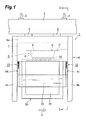
Fig. 1] Fig. 1 is a side view of an overhead transport carriage of an embodiment of the present invention. - [
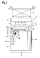
Fig. 2] Fig. 2 is a sectional view of the overhead transport carriage taken along line II-II inFig. 1 . - [
Fig. 3] Fig. 3 is a view illustrating the up-and-down motion of an object to be conveyed in the overhead transport carriage inFig. 2 . - [
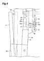
Fig. 4] Fig. 4 is an enlarged view of a main part of the overhead transport carriage inFig. 2 . - The following describes a preferred embodiment of the present invention in detail with reference to the accompanying drawings. Note that, the same components are denoted by the same reference signs in each drawing, and redundant descriptions are omitted.
- As illustrated in
Fig. 1 , thisoverhead transport carriage 1 conveys an object to be conveyed 30 along a traveling rail (conveying route) 3. The travelingrail 3 is mounted, viastays 2, on the ceiling of a clean room for manufacturing semiconductor devices. The object to be conveyed 30 is a cassette that contains a plurality of semiconductor wafers (what is called a FOUP (Front Opening Unified Pod)). Adetachable lid 31 through which the semiconductor wafers are taken out and put in is attached to a side of the object to be conveyed 30. Furthermore, aflange 32 held with theoverhead transport carriage 1 is provided to the top surface of the object to be conveyed 30. - The
overhead transport carriage 1 includes abody 4 containing the object to be conveyed 30 and traveling along the travelingrail 3. Thebody 4 is suspended from the travelingrail 3 viatraveling units 5. Each of thetraveling units 5 includes a driving wheel and a guide wheel that contact with the inner surface of the travelingrail 3, thus thebody 4 travels along thetraveling rail 3. Furthermore, thetraveling unit 5 includes an electromagnetic coil unit disposed on a part surrounded by thetraveling rail 3, thereby receiving power, without contact, from a wire for high frequency current installed in thetraveling rail 3. - The
body 4 includes abase frame 4a on which thetraveling unit 5 is mounted. The front side and the rear side of thebase frame 4a in a conveying direction A are provided with afront frame 4b and arear frame 4c extending downward, respectively. The object to be conveyed 30 is loaded between thefront frame 4b and therear frame 4c in a state that thelid 31 is directed in a lateral direction with respect to the conveying direction A. Note that, in the following description, a side that thelid 31 directs to is referred to as "one side", and the opposite side thereof is referred to as "the other side", with respect to the conveying direction A. - The
base frame 4a is provided with alifting mechanism 6. Thelifting mechanism 6 includes alifting unit 7 and aholding unit 8. Theholding unit 8 holds the object to be conveyed 30 by holding theflange 32. Thelifting unit 7 moves theholding unit 8 up and down with respect to a predetermined position P at which the containing of the object to be conveyed 30 is performed. More specifically, thelifting unit 7 sends out a plurality ofbelts 9 synchronously, thus theholding unit 8 attached to the ends of thebelts 9 moves down from the position P. By contrast, thelifting unit 7 winds up the plurality ofbelts 9 synchronously, thus theholding unit 8 attached to the ends of thebelts 9 moves up to the position P. Thebase frame 4a may be provided with a cross feeder displacing thelifting unit 7 to the one side or the other side with respect to the conveying direction A, and a θ drive rotating thelifting unit 7 in a horizontal plane, or other units. - With the above-mentioned configuration, the
overhead transport carriage 1 works as follows: theoverhead transport carriage 1 stops above a port of a conveyance source (for example, a semiconductor processing apparatus) to contain in thebody 4, the object to be conveyed 30 placed on the port by lifting up thelifting mechanism 6. Subsequently, theoverhead transport carriage 1 carries the object to be conveyed 30 along the travelingrail 3. Thereafter, theoverhead transport carriage 1 stops above a port of the conveyance destination (for example, a semiconductor processing apparatus) to arrange the object to be conveyed 30 loaded in thebody 4 on the port by moving down thelifting mechanism 6. - As illustrated in
Fig. 1 andFig. 2 , theoverhead transport carriage 1 includes an anti lid-dropping-offmember 20 facing thelid 31 of the object to be conveyed 30 when theholding unit 8 is located at the predetermined position P, and a movingmechanism 10 moving the anti lid-dropping-offmember 20 in response to the up-and-down motion of theholding unit 8. The anti lid-dropping-offmember 20 is a sheet member having flexibility (for example, thin fluorocarbon resins, such as Teflon that is a registered trademark) and is supported with the movingunit 10 along the conveying direction A so as to cross the front of thelid 31. - The moving
unit 10 includes a pair of swing arms (second swinging unit) 11 extending from the one side to the other side with respect to the conveying direction A. The pair of theswing arms 11 is installed between theframes unit 8 arranged on the predetermined position P. Oneend 11a of each of theswing arms 11 is rotationally supported with a correspondingshaft 12 standing on theframe other end 11b of eachswing arm 11 is provided with a receivingpart 13 extending toward the inside. The receivingparts 13 of therespective swing arms 11 abut on anupper surface 8a of the holdingunit 8 when the holdingunit 8 is located at the predetermined position P. Therespective swing arms 11 swing about theshafts 12 between an upward position where the receivingpart 13 is located at the position P and a downward position where the receivingpart 13 is located lower than the position P. Note that when the holdingunit 8 is located at the position P, the lower surface of the receivingpart 13 and theupper surface 8a of the holdingunit 8 are nearly located at the position P. - The one
end 11a of eachswing arm 11 is connected to another swing arm (first swinging unit) 14 extending downward. Therespective swing arms 14 swing about theshafts 12 between a forward position where theswing arms 11 are located at the upward position and a backward position where theswing arms 11 are located at the downward position. - Both
swing arms 14 are attached with the anti lid-dropping-off member 20. More specifically, with respect to the conveying direction A, both lateral ends of the anti lid-dropping-off member 20 are subjected to bending and are fixed to therespective swing arms 14. The anti lid-dropping-off member 20 swings about theshafts 12 between an anti dropping-off position (first position) where theswing arms swing arms off member 20 facing thelid 31 is apart from the surface of thelid 31 with a distance of several millimeters, prevents thelid 31 from dropping off. The escape position is a position farther from thelid 31 than the anti dropping-off position. - The moving
mechanism 10 and the anti lid-dropping-off member 20 configured as above work as follows. In the case where the holdingunit 8 moves down from the predetermined position P as illustrated inFig. 2 andFig. 3 , theswing arms 14 reverse from the forward position to the backward position as theswing arms 11 move down from the upward position to the downward position due to the weight thereof if the holdingunit 8 moves down from the position P by a predetermined distance D. With this configuration, the anti lid-dropping-off member 20 moves from the anti dropping-off position to the escape position. In other words, theswing arms 11 swing from the upward position to the downward position and theswing arms 14 swing from the forward position to the backward position when the holdingunit 8 moves down by the predetermined distance D from the predetermined position P, thereby moving the anti lid-dropping-off member 20 from the anti dropping-off position to the escape position. - By contrast, in the case where the holding
unit 8 moves up to the predetermined position P, theswing arms 14 move from the backward position to the forward position as theswing arms 11 move up from the downward position to the upward position because the holdingunit 8 lifts the receivingpart 13. With this configuration, the anti lid-dropping-off member 20 moves from the escape position to the anti dropping-off position. In other words, theswing arms 11 swing from the downward position to the upward position and theswing arms 14 swing from the backward position to the forward position when the holdingunit 8 moves up by the predetermined distance D from the predetermined position P, thereby moving the anti lid-dropping-off member 20 from the escape position to the anti dropping-off position. - As mentioned above, the moving
mechanism 10 moves the anti lid-dropping-off member 20 in response to the up-and-down motion of the holdingunit 8 so that the anti lid-dropping-off member 20 is located at the anti dropping-off position when the holdingunit 8 is located at the position P and the anti lid-dropping-off member 20 is located at the escape position when the holdingunit 8 moves up and down with respect to the position P. - Next, the
swing arms 14 of the movingmechanism 10 are described in more detail. As illustrated inFig. 4 , eachswing arm 14 includes a base-end part 15 connected to the oneend 11 a of eachswing arm 11 and a tip-end part 16 fixed to the anti lid-dropping-off member 20. Such base-end parts 15 and tip-end parts 16 are rotationally connected throughshafts 17. Note that the rotational range of the tip-end part 16 relative to the base-end part 15 is restricted withrotation restricting members - Thus, the
rotation restricting members 25 formed on the base-end parts 15 each are provided with end faces 25a and 25b having predetermined angles to form a convex toward the tip-end parts 16. Therotation restricting members 26 formed on the tip-end parts 16 are provided with end faces 26a so as to abut on the respective end faces 25a and 25b on therotation restricting members 25 by rotational motion about theshafts 17. With this configuration, the tip-end parts 16 rotate with respect to the base-end parts 15 between the state where theend face 26a abuts on theend face 25a (the anti lid-dropping-off member 20 is arranged at the anti dropping-off position) and the state where theend face 26a abuts on theend face 25b (the anti lid-dropping-off member 20 is located at a position outer than the anti dropping-off position). -
Brackets end part 15 and the tip-end part 16, respectively. Apull spring 21 is stretched between thebrackets end part 16 is urged to the base-end part 15 so that theend face 26a comes into contact with theend face 25a. In addition to that, adisplacement detector 22, such as a photo-interrupter having a light emitting element and a light receiving element, is fixed to the base-end part 15, and alight shielding plate 23 is fixed to the tip-end part 16. With this configuration, thelight shielding plate 23 blocks a light path (the light path from the light emitting element to the light receiving element) when the tip-end part 16 rotationally moves with respect to the base-end part 15 so that theend face 26a comes into contact with theend face 25b. - As described above, the moving
mechanism 10 supports the anti lid-dropping-off member 20 so that the anti lid-dropping-off member 20 displaces toward the escape position by a predetermined amount when external force toward the escape position acts on the anti lid-dropping-off member 20 located at the anti dropping-off position. In addition to that, the light path of thedisplacement detector 22 is blocked by thelight shielding member 23 when the anti lid-dropping-off member 20 displaces toward the escape position by a predetermined amount, thereby detecting the displacement of the anti lid-dropping-off member 20 toward the escape position. - As described above, in the
overhead transport carriage 1, the anti lid-dropping-off member 20 is located at the anti dropping-off position for preventing thelid 31 from dropping off when the holdingunit 8 holding the object to be conveyed 30 is located at the predetermined position P. With this configuration, thelid 31 is prevented from dropping off the object to be conveyed 30 during conveyance. The anti lid-dropping-off member 20 is located at the escape position farther from the lid than the anti dropping-off position when the holdingunit 8 holding the object to be conveyed 30 is moved up and down with respect to the predetermined position P. With this configuration, the up-and-down motion of the object to be conveyed 30 is prevented from being blocked. In addition to the above, the movingmechanism 10 moves the anti lid-dropping-off member 20 between the anti dropping-off position and the escape position in response to the up-and-down motion of the holdingunit 8. With theoverhead transport carriage 1, therefore, thelid 31 is prevented from dropping off when the object to be conveyed 30 is conveyed and the up-and-down motion of the object to be conveyed 30 is prevented from being blocked with a simple structure. Furthermore, a dedicated actuator or other devices to move the anti lid-dropping-off member 20 is not necessary, thus the power consumption in theoverhead transport carriage 1 can be reduced. - In the
overhead transport carriage 1, if the holdingunit 8 does not hold the object to be conveyed 30, the anti lid-dropping-off member 20 is located at the anti dropping-off position when the holdingunit 8 is located at the predetermined position P. With this configuration, the anti lid-dropping-off member 20 is prevented from contacting with an external device or other instruments when theoverhead transport carriage 1 does not contain the object to be conveyed 30 and travels along the travelingrail 3 in an unloaded state. Moreover, the anti lid-dropping-off member 20 is located at the escape position as long as the holdingunit 8 moves up and down with respect to the predetermined position P although the object to be conveyed 30 is not being held by the holdingunit 8. With this configuration, the up-and-down motion of the holdingunit 8 is prevented from being blocked when the holdingunit 8 not holding the object to be conveyed 30 moves up and down. - The moving
mechanism 10 includes theswing arms off member 20 following the up-and-down motion of the holdingunit 8. With this configuration, in theoverhead transport carriage 1, the structure of the movingmechanism 10 is simplified and the reliability in the mechanical motion of the movingmechanism 10 is improved. - The moving
mechanism 10 supports the anti lid-dropping-off member 20 so that the anti lid-dropping-off member 20 displaces toward the escape position by a predetermined amount when external force toward the escape position acts on the anti lid-dropping-off member 20 located at the anti dropping-off position. The movingmechanism 10 includes thedisplacement detector 22 detecting displacement of the anti lid-dropping-off member 20 toward the escape position. With this configuration, the anti lid-dropping-off member 20 located at the anti dropping-off position displaces toward the escape position if thelid 31 is about to drop off from the object to be conveyed 30 during conveyance, for example. In this case, thedisplacement detector 22 detects the displacement of the anti lid-dropping-off member 20 toward the escape position, thereby recognizing that thelid 31 is about to drop off from the object to be conveyed 30. With this configuration, it is possible to take quick actions, such as suspending the travel of the object to be conveyed 30 if thelid 31 is about to drop off and interrupting the conveyance of the object to be conveyed 30 for fixing thelid 31 to the object to be conveyed 30. - A part of the anti lid-dropping-
off member 20 at least facing thelid 31 of the object to be conveyed 30 includes a sheet member having flexibility. With this configuration, the anti lid-dropping-off member 20 is prevented from protruding from thebody 4 when the anti lid-dropping-off member 20 is installed. In addition, thelid 31 is securely caught even if thelid 31 drops off the object to be conveyed 30. Furthermore, the anti lid-dropping-off member 20 deforms easily if the lid dropping-off member 20 contacts with an external device or other instruments, thereby preventing the external device or other instruments from being damaged. - The present invention has been described above in detail based on an embodiment thereof. However, the present invention is not limited to the embodiment described above. For example, as long as the moving
mechanism 10 moves the anti lid-dropping-off member 20 in response to the up-and-down motion of the holdingunit 8 so that the anti lid-dropping-off member 20 is located at the anti dropping-off position (first position) when the holdingunit 8 is located at the position P and the anti lid-dropping-off member 20 is located at the escape position (second position) when the holdingunit 8 moves up and down with respect to the position P, the movingmechanism 10 is not limited to the configuration including theswing arms mechanism 10 may cramp the anti lid-dropping-off member 20 including a sheet member to locate it at the anti dropping-off position and release the anti lid-dropping-off member 20 to locate it at the escape position. - The
overhead transport carriage 1 is not limited to an apparatus that conveys the object to be conveyed 30 along the travelingrail 3 mounted in a clean room for manufacturing semiconductor devices. The object to be conveyed 30 is not limited to a cassette containing therein a plurality of semiconductor wafers. The materials and shapes of theoverhead transport carriage 1 and the object to be conveyed 30 are not limited to the material and shape described above. Various kinds of materials and shapes can be applied to them. - According to the present invention, an unsafe state in which the lid is about to drop off the object to be conveyed during conveyance is detected quickly, the lid is prevented from dropping off the object to be conveyed during conveyance, and the up-and-down motion of the object to be conveyed is prevented from being blocked with a simple structure.
- 1... overhead transport carriage, 3... traveling rail (conveying route), 4... body, 6... lifting mechanism, 7... lifting unit, 8... holding unit, 10... moving mechanism, 11... swing arm (second swinging unit), 14... swing arm (first swinging unit), 20... anti lid-dropping-off member, 22... displacement detector, 30... object to be conveyed, 31... lid.
Claims (4)
- An overhead transport carriage conveying an object to be conveyed with a detachable lid along a conveying route, the overhead transport carriage comprising:a body containing the object to be conveyed and traveling along the conveying route;a lifting mechanism including a holding unit holding the object to be conveyed and a lifting unit moving the holding unit up and down with respect to a predetermined position at which the object to be conveyed is contained;an anti lid-dropping-off member facing the lid when the holding unit is located at the predetermined position; anda moving mechanism moving the anti lid-dropping-off member in response to up-and-down motion of the holding unit so that the anti lid-dropping-off member is located at a first position for preventing the lid from dropping off when the holding unit is located at the predetermined position and the anti lid-dropping-off member is located at a second position farther from the lid than the first position when the holding unit moves up and down with respect to the predetermined position.
- The overhead transport carriage according to claim 1, wherein
the moving mechanism includes a first swinging unit provided with the anti lid-dropping-off member and swinging between a forward position and a backward position, and a second swinging unit connected to the first swinging unit and swinging between an upward position and a downward position,
the second swinging unit swings from the downward position to the upward position and the first swinging unit swings from the backward position to the forward position when the holding unit moves up by a predetermined distance from the predetermined position, thereby moving the anti lid-dropping-off member from the second position to the first position, and
the second swinging unit swings from the upward position to the downward position and the first swinging unit swings from the forward position to the backward position when the holding unit moves down by the predetermined distance, thereby moving the anti lid-dropping-off member from the first position to the second position. - The overhead transport carriage according to claim 1 or 2, wherein
the moving mechanism supports the anti lid-dropping-off member so that the anti lid-dropping-off member displaces toward the second position by a predetermined amount when external force toward the second position acts on the anti lid-dropping-off member located at the first position, and
the moving mechanism includes a displacement detector detecting displacement of the anti lid-dropping-off member toward the second position. - The overhead transport carriage according to any one of claims 1 to 3, wherein
a part of the anti lid-dropping-off member at least facing the lid includes a sheet member having flexibility.
Applications Claiming Priority (2)
| Application Number | Priority Date | Filing Date | Title |
|---|---|---|---|
| JP2011110330 | 2011-05-17 | ||
| PCT/JP2012/055466 WO2012157319A1 (en) | 2011-05-17 | 2012-03-02 | Overhead transport carriage |
Publications (2)
| Publication Number | Publication Date |
|---|---|
| EP2711980A1 true EP2711980A1 (en) | 2014-03-26 |
| EP2711980A4 EP2711980A4 (en) | 2014-11-26 |
Family
ID=47176661
Family Applications (1)
| Application Number | Title | Priority Date | Filing Date |
|---|---|---|---|
| EP12786517.8A Withdrawn EP2711980A4 (en) | 2011-05-17 | 2012-03-02 | AIR TRANSPORT TROLLEY |
Country Status (8)
| Country | Link |
|---|---|
| US (1) | US9284164B2 (en) |
| EP (1) | EP2711980A4 (en) |
| JP (1) | JP5561432B2 (en) |
| KR (1) | KR101523537B1 (en) |
| CN (1) | CN103534798B (en) |
| SG (1) | SG194979A1 (en) |
| TW (1) | TW201247516A (en) |
| WO (1) | WO2012157319A1 (en) |
Families Citing this family (18)
| Publication number | Priority date | Publication date | Assignee | Title |
|---|---|---|---|---|
| JP5949717B2 (en) * | 2013-09-26 | 2016-07-13 | 村田機械株式会社 | Transport device for container with lid and support method for lid |
| JP6064940B2 (en) * | 2014-04-07 | 2017-01-25 | 株式会社ダイフク | Goods transport vehicle |
| WO2016027558A1 (en) * | 2014-08-18 | 2016-02-25 | 村田機械株式会社 | Transport device and transport method |
| JP6327124B2 (en) * | 2014-11-12 | 2018-05-23 | 株式会社ダイフク | Goods transport vehicle |
| JP6269535B2 (en) * | 2015-03-04 | 2018-01-31 | 株式会社ダイフク | Goods transport equipment |
| EP3460834B1 (en) * | 2016-05-20 | 2020-08-05 | Murata Machinery, Ltd. | Transport vehicle and transport method |
| JP6696406B2 (en) * | 2016-10-31 | 2020-05-20 | 株式会社ダイフク | Transfer machine |
| WO2018142811A1 (en) * | 2017-02-06 | 2018-08-09 | 村田機械株式会社 | Overhead conveyance vehicle |
| JP6769336B2 (en) * | 2017-02-23 | 2020-10-14 | 株式会社ダイフク | Goods carrier |
| US10964573B2 (en) * | 2017-03-28 | 2021-03-30 | Murata Machinery, Ltd. | Ceiling carrier vehicle |
| JP6794946B2 (en) * | 2017-07-11 | 2020-12-02 | 株式会社ダイフク | Goods carrier |
| TWI638760B (en) | 2018-01-19 | 2018-10-21 | 台灣積體電路製造股份有限公司 | Wafer-transport vehicle and wafer-carrier detection method |
| KR102387549B1 (en) * | 2018-01-24 | 2022-04-19 | 무라다기카이가부시끼가이샤 | carrier |
| WO2019146276A1 (en) * | 2018-01-24 | 2019-08-01 | 村田機械株式会社 | Transport vehicle |
| JP6881486B2 (en) * | 2019-02-27 | 2021-06-02 | 村田機械株式会社 | Transport vehicle |
| JP7378895B2 (en) * | 2019-11-20 | 2023-11-14 | 株式会社ディスコ | Transport vehicle |
| WO2021181923A1 (en) * | 2020-03-13 | 2021-09-16 | 村田機械株式会社 | Gripper device, conveyance vehicle, and conveyance method |
| JP7480797B2 (en) * | 2022-03-14 | 2024-05-10 | 村田機械株式会社 | Overhead transport vehicle system |
Family Cites Families (9)
| Publication number | Priority date | Publication date | Assignee | Title |
|---|---|---|---|---|
| WO1987004043A1 (en) * | 1985-12-23 | 1987-07-02 | Asyst Technologies | Box door actuated retainer |
| JP3885232B2 (en) * | 2003-03-14 | 2007-02-21 | 村田機械株式会社 | Transport cart |
| JP2004315191A (en) * | 2003-04-18 | 2004-11-11 | Daifuku Co Ltd | Fall preventing device for article storage facility |
| JP2006298566A (en) * | 2005-04-20 | 2006-11-02 | Murata Mach Ltd | Overhead vehicle and its system |
| JP4264840B2 (en) * | 2006-10-20 | 2009-05-20 | 村田機械株式会社 | Overhead traveling car |
| JP5266680B2 (en) * | 2007-07-23 | 2013-08-21 | 村田機械株式会社 | Conveying device, conveying system, and extension mechanism |
| JP5217416B2 (en) * | 2007-12-25 | 2013-06-19 | 村田機械株式会社 | Storage and entry / exit methods |
| US8490802B2 (en) * | 2008-05-22 | 2013-07-23 | Murata Machinery, Ltd. | Overhead conveying vehicle |
| JP2011035022A (en) * | 2009-07-30 | 2011-02-17 | Murata Machinery Ltd | Overhead carrier |
-
2012
- 2012-03-02 KR KR1020137026060A patent/KR101523537B1/en not_active Expired - Fee Related
- 2012-03-02 CN CN201280023186.1A patent/CN103534798B/en not_active Expired - Fee Related
- 2012-03-02 US US14/117,824 patent/US9284164B2/en not_active Expired - Fee Related
- 2012-03-02 SG SG2013084645A patent/SG194979A1/en unknown
- 2012-03-02 JP JP2013515024A patent/JP5561432B2/en not_active Expired - Fee Related
- 2012-03-02 EP EP12786517.8A patent/EP2711980A4/en not_active Withdrawn
- 2012-03-02 WO PCT/JP2012/055466 patent/WO2012157319A1/en not_active Ceased
- 2012-05-14 TW TW101117104A patent/TW201247516A/en unknown
Also Published As
| Publication number | Publication date |
|---|---|
| JP5561432B2 (en) | 2014-07-30 |
| WO2012157319A1 (en) | 2012-11-22 |
| JPWO2012157319A1 (en) | 2014-07-31 |
| US20140144859A1 (en) | 2014-05-29 |
| EP2711980A4 (en) | 2014-11-26 |
| TW201247516A (en) | 2012-12-01 |
| KR20130131460A (en) | 2013-12-03 |
| US9284164B2 (en) | 2016-03-15 |
| CN103534798A (en) | 2014-01-22 |
| CN103534798B (en) | 2016-01-06 |
| KR101523537B1 (en) | 2015-05-28 |
| SG194979A1 (en) | 2013-12-30 |
Similar Documents
| Publication | Publication Date | Title |
|---|---|---|
| US9284164B2 (en) | Overhead transport carriage | |
| CN106927206B (en) | Item Conveying Equipment | |
| EP3505416B1 (en) | Rail-guided trolley system, and rail-guided trolley | |
| TWI724239B (en) | Overhead transport system and overhead transport vehicle | |
| EP3460834B1 (en) | Transport vehicle and transport method | |
| KR102422206B1 (en) | Transport device | |
| JP2016163001A (en) | Gripper device, transfer device, and transfer method | |
| CN113165189A (en) | Substrate conveying device and operation method thereof | |
| CN108016953B (en) | Transfer machine | |
| TW201538411A (en) | Item support device | |
| KR101599946B1 (en) | Apparatus for transferring plate | |
| JPWO2018186021A1 (en) | Ceiling carrier system and teaching unit | |
| EP4109502A1 (en) | Gripper device, conveyance vehicle, and conveyance method | |
| KR20180047214A (en) | Apparatus for transferring using the integrated circuit device fabricating | |
| KR20220024899A (en) | Substrate mapping apparatus, mapping method thereof, and mapping teaching method | |
| WO2016027558A1 (en) | Transport device and transport method | |
| JPWO2020174846A1 (en) | Transfer device and ceiling carrier | |
| KR20210017168A (en) | Apparatus for transporting carrier and system for controlling the apparatus | |
| JP5151276B2 (en) | Transport system | |
| JP5056368B2 (en) | Transport system | |
| KR102356962B1 (en) | Transfer machine | |
| US20180129141A1 (en) | Transferring apparatus | |
| JP2017088394A (en) | Transport device and ceiling carrier | |
| KR102578557B1 (en) | Overhead Hoist Transfer and Method of Transferring using the same | |
| KR102844017B1 (en) | Transferring unit and stocker having the same |
Legal Events
| Date | Code | Title | Description |
|---|---|---|---|
| PUAI | Public reference made under article 153(3) epc to a published international application that has entered the european phase |
Free format text: ORIGINAL CODE: 0009012 |
|
| 17P | Request for examination filed |
Effective date: 20131121 |
|
| AK | Designated contracting states |
Kind code of ref document: A1 Designated state(s): AL AT BE BG CH CY CZ DE DK EE ES FI FR GB GR HR HU IE IS IT LI LT LU LV MC MK MT NL NO PL PT RO RS SE SI SK SM TR |
|
| DAX | Request for extension of the european patent (deleted) | ||
| A4 | Supplementary search report drawn up and despatched |
Effective date: 20141024 |
|
| RIC1 | Information provided on ipc code assigned before grant |
Ipc: B61B 3/02 20060101ALI20141020BHEP Ipc: H01L 21/677 20060101AFI20141020BHEP Ipc: B65G 49/07 20060101ALI20141020BHEP Ipc: B61B 13/06 20060101ALI20141020BHEP Ipc: B65G 1/04 20060101ALI20141020BHEP |
|
| STAA | Information on the status of an ep patent application or granted ep patent |
Free format text: STATUS: THE APPLICATION HAS BEEN WITHDRAWN |
|
| 18W | Application withdrawn |
Effective date: 20170201 |