EP2711866A1 - Procédé et système pour détecter un code-barres en 2D dans une étiquette circulaire - Google Patents
Procédé et système pour détecter un code-barres en 2D dans une étiquette circulaire Download PDFInfo
- Publication number
- EP2711866A1 EP2711866A1 EP12185478.0A EP12185478A EP2711866A1 EP 2711866 A1 EP2711866 A1 EP 2711866A1 EP 12185478 A EP12185478 A EP 12185478A EP 2711866 A1 EP2711866 A1 EP 2711866A1
- Authority
- EP
- European Patent Office
- Prior art keywords
- region
- barcode
- substantially circular
- circular
- circular region
- Prior art date
- Legal status (The legal status is an assumption and is not a legal conclusion. Google has not performed a legal analysis and makes no representation as to the accuracy of the status listed.)
- Withdrawn
Links
Images


Classifications
-
- G—PHYSICS
- G06—COMPUTING; CALCULATING OR COUNTING
- G06K—GRAPHICAL DATA READING; PRESENTATION OF DATA; RECORD CARRIERS; HANDLING RECORD CARRIERS
- G06K7/00—Methods or arrangements for sensing record carriers, e.g. for reading patterns
- G06K7/10—Methods or arrangements for sensing record carriers, e.g. for reading patterns by electromagnetic radiation, e.g. optical sensing; by corpuscular radiation
- G06K7/14—Methods or arrangements for sensing record carriers, e.g. for reading patterns by electromagnetic radiation, e.g. optical sensing; by corpuscular radiation using light without selection of wavelength, e.g. sensing reflected white light
- G06K7/1404—Methods for optical code recognition
- G06K7/1439—Methods for optical code recognition including a method step for retrieval of the optical code
- G06K7/1443—Methods for optical code recognition including a method step for retrieval of the optical code locating of the code in an image
-
- G—PHYSICS
- G06—COMPUTING; CALCULATING OR COUNTING
- G06K—GRAPHICAL DATA READING; PRESENTATION OF DATA; RECORD CARRIERS; HANDLING RECORD CARRIERS
- G06K7/00—Methods or arrangements for sensing record carriers, e.g. for reading patterns
- G06K7/10—Methods or arrangements for sensing record carriers, e.g. for reading patterns by electromagnetic radiation, e.g. optical sensing; by corpuscular radiation
- G06K7/14—Methods or arrangements for sensing record carriers, e.g. for reading patterns by electromagnetic radiation, e.g. optical sensing; by corpuscular radiation using light without selection of wavelength, e.g. sensing reflected white light
- G06K7/1404—Methods for optical code recognition
- G06K7/1439—Methods for optical code recognition including a method step for retrieval of the optical code
- G06K7/1456—Methods for optical code recognition including a method step for retrieval of the optical code determining the orientation of the optical code with respect to the reader and correcting therefore
-
- G—PHYSICS
- G06—COMPUTING; CALCULATING OR COUNTING
- G06K—GRAPHICAL DATA READING; PRESENTATION OF DATA; RECORD CARRIERS; HANDLING RECORD CARRIERS
- G06K19/00—Record carriers for use with machines and with at least a part designed to carry digital markings
- G06K19/06—Record carriers for use with machines and with at least a part designed to carry digital markings characterised by the kind of the digital marking, e.g. shape, nature, code
- G06K19/06009—Record carriers for use with machines and with at least a part designed to carry digital markings characterised by the kind of the digital marking, e.g. shape, nature, code with optically detectable marking
- G06K19/06037—Record carriers for use with machines and with at least a part designed to carry digital markings characterised by the kind of the digital marking, e.g. shape, nature, code with optically detectable marking multi-dimensional coding
-
- G—PHYSICS
- G06—COMPUTING; CALCULATING OR COUNTING
- G06K—GRAPHICAL DATA READING; PRESENTATION OF DATA; RECORD CARRIERS; HANDLING RECORD CARRIERS
- G06K7/00—Methods or arrangements for sensing record carriers, e.g. for reading patterns
- G06K7/10—Methods or arrangements for sensing record carriers, e.g. for reading patterns by electromagnetic radiation, e.g. optical sensing; by corpuscular radiation
- G06K7/14—Methods or arrangements for sensing record carriers, e.g. for reading patterns by electromagnetic radiation, e.g. optical sensing; by corpuscular radiation using light without selection of wavelength, e.g. sensing reflected white light
- G06K7/1404—Methods for optical code recognition
- G06K7/1408—Methods for optical code recognition the method being specifically adapted for the type of code
- G06K7/1417—2D bar codes
Definitions
- the present invention relates to a method and system for barcode reading.
- the present invention relates to a method and system for localizing a barcode (e.g. a 2D barcode) placed on a circular region, particularly on a circular label.
- a barcode e.g. a 2D barcode
- the problem of scanning barcodes can be applied to a large variety of application contexts, in the present application, without loss of generality, we concretely address a specific example in the engineering of a barcode reader in an electromechanical system for biological analyses.
- the barcode reading system has been implemented in the The Vitek ImmunoDiagnostic Assay System manufactured and distributed by bioMerieux also known as VIDAS ® or VIDAS ® 3 in its more recent version. It is a compact automated multiparametric immunoanalyzer that uses predispensed disposable reagent strips and specially coated Solid Phase Receptacles (SPR ® ).
- the VIDAS ® 3 can pipette directly from the primary sample tube, mix, incubate, control and analyze samples.
- the VIDAS ® 3 has four independent sections, where each section can run up to 3 samples. Additional features allow the VIDAS ® 3 to perform sample handling from primary tubes automatically. The operator introduces the centrifuged, uncapped tubes, SPR ® and strips into the instrument. All remaining operations (barcode reading of the primary tubes and sample aspiration from primary tubes) are handled by the system automatically. VIDAS ® 3 reagent strip processing, algorithms, analysis and kit components used (strips, SPR ® , etc.) are all identical to the current VIDAS ® and mini VIDAS ® .
- the VIDAS ® 3 will offer routine batch or random access (mixed) testing for serology, immunochemistry, antigen detection and immunohemostasis.
- the immunological methods are indirect EIA, immunocapture, sandwich or competition, all involving a conjugate using the alkaline phosphatase.
- the VIDAS ® 3 uses instrument protocols as defined for each assay product. These protocols are automatically selected in the computer knowledge base through bar-coded information on the product packaging. The user confirms assay selection through user menus. Test results are transmitted to the computer to be analyzed and printed.
- the system is able to concurrently run multiple analyses, which comprise sequences of actions performed on the sample by shared mechanical components; the maximum duration of each analysis is limited by biological constraints, but waiting times between subsequent actions are allowed to range in a non-deterministic interval.
- Each type of biological analysis is comprised by a pretreatment phase and an analytic protocol.
- a cone shaped test-tube uniquely identified by a barcode contains the sample, other tubes arranged as a strip of multiple containers, contain dilution and incubation fluids.
- an automatic pipettor repeatedly pours off the sample among the various tubes; each pipettor action lasts for a deterministic amount of time. Waiting times are allowed between successive actions, but they are constrained to range between minimum and maximum values determined by incubation/reaction periods and sample deterioration properties.
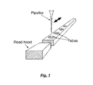
- the analytic protocol follows a fixed sequence of steps during which the sample is combined with reagents and multiple measurements are taken by a read-head.
- read-head actions are deterministic and interleaved with waiting times (see Fig. 1 ).
- multiple analyses also of different types, are carried out concurrently.
- the system composes multiple sections, one for each analysis.
- Each section is in turn divided in slots, carrying different samples that can be subject to different pretreatments and can operate on samples of different subjects.
- the read-head is designed to take measures on a whole section at once, all slots in the same section are constrained to run the same analytic protocol (see Fig. 2 ).
- the pipettor and the read-head are shared among different slots and sections and cannot be used simultaneously by two different analyses.
- a further object of the present invention is to provide a method for identifying the position of a 2D barcode image on a substantially circular label in a fast and reliable way.
- Another object of the invention is to provide an electromechanical apparatus for performing biological analyses having a barcode reader capable of localizing and reading a 2D barcode image on a substantially circular label.
- the present disclosure provides a method for determining, with a digital image processing system, the position of a rectangular data matrix within a substantially circular region, the data matrix being positioned within a predetermined portion of a circular crown region, the circular crown region being defined by an inner circle and by an outer circle having the center substantially coincident with the center of the substantially circular region, the predetermined portion of the circular crown region being identified by at least one visual mark, the method including the steps of: acquiring a digital representation of the substantially circular region; determining the center of the substantially circular region; building a detecting ring area including the inner and the outer circles; radially scanning the detecting ring area to identify the at least one visual mark indicative of the start position of the predetermined portion of the circular crown region; starting from the start position, scanning the detecting ring area to determine the position of the border of the data matrix.
- the predetermined portion of a circular crown region is included in a circular segment, the minimum contrast between the circular segment and the rest of the substantially circular region exceeding a predetermined threshold and the at least one visual mark is represented by a position where the circular crown region intersects the chord defining the circular segment.
- the data matrix represents a 2D barcode and the background of the circular segment where the data matrix is positioned is black.
- the area covered by the circular segment is at most 90% of the total area of the substantially circular region, preferably at most 70% and more preferably at most 50%. In a more preferable manner, the area covered by the circular segment is less than 50% of the total area of the substantially circular region.
- acquiring a digital representation includes capturing by means of a digital image processing system a black and white rectangular picture including the substantially circular region, the rectangular picture including an array of pixels each pixel having a level of gray and storing the representation within the digital image processing.
- the step of determining the center of the substantially circular region includes: identifying the edge of the substantially circular region within the rectangular picture; determining the center of the substantially circular region with respect to the identified edge.
- identifying the edge of the substantially circular region includes: horizontally scanning the rectangular picture to identify a transition point where the difference between the level of gray of neighboring pixels is exceeding a predetermined value, the horizontal transition point being indicative of a lateral edge of the substantially circular region; vertically scanning the rectangular picture to identify a transition point where the difference between the level of gray of neighboring pixels is exceeding a predetermined value, the vertical transition point being indicative of a vertical edge of the substantially circular region.
- the step of building a detecting ring area includes determining a circular crown included between an internal radius and an external radius with respect to the center of the substantially circular region.
- a computer program including program code means which, when executed on a computer, implements the above method.
- a barcode reading system including the above system for determining the position of a rectangular data matrix within a substantially circular region. Also provided is an electromechanical system for performing biological analyses, including the barcode reading system.
- the present invention offers a number of benefits.
- One of the advantages of a preferred embodiment of the present invention is that a simplified, low resource consuming image recognition software addresses the need of identifying, localizing and reading a barcode on a circular shaped label.
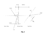
- a detecting device e.g. a camera including a sensor 101 and a lens 103 being inclined with an angle ⁇ (e.g. 35°) with respect to the target 105 is represented in Figure 3 .
- the target in the present example, is a circular label carrying a barcode which is applied on top of a cone-shaped tube. Such tube must match with a corresponding strip as mentioned above.
- the task to be performed by the system which implements an embodiment of the present disclosure is to acquire the image represented on the label on target 105, localize the barcode (e.g. a 2D barcode) and read the information contained in the barcode. Such information can then be used to verify the correct matching between the cone and the strip.
- the barcode e.g. a 2D barcode
- a 2D barcode is normally represented with a DataMatrix, i.e. a two-dimensional matrix consisting of black and white "cells" or modules arranged in either a square or rectangular pattern.
- the information to be encoded can be text or raw data.
- the detecting device is controlled by a computer or microprocessor having a code embedded on firmware; e.g. in the practical example here described, the microprocessor is a processor based on a ARM9 core, running up to 400 Mhz mainly targeted for multimedia and low power applications. This processor is needed in order to provide enough capability to acquire the image and decode the DataMatrix (DMTX) code.
- the microprocessor is equipped with a FLASH, RAM and EEPROM memory: FLASH memory is used to store the application and the FW code; RAM memory is used to execute code and store both image information and temporary information during the DataMatrix decoding process.
- EEPROM memory is used to store relevant data such as parameter of the camera board or calibration data.
- Such computer runs a software which processes the image captured by the detecting device 101 which, in a preferred embodiment of the present disclosure, is mounted on a board.
- the software includes a Data Matrix Decoding Algorithm (DDA) which is able to decode a Data Matrix (DMTX) of a fixed size (e.g. code density of 8x18 squares with any single element side size of 5mils (0.127 mm) with ECC200.
- DDA Data Matrix Decoding Algorithm
- DMTX Data Matrix
- ECC200 is a recent version of Data Matrix and supports advanced encoding error checking and correction algorithms. ECC200 allows the routine reconstruction of the entire encoded data string when the symbol has sustained up to 30% damage, assuming the matrix can still be accurately located.
- the optimal working distance, between the detecting device and the target plane is comprised between 106mm and 98mm, e.g. 102.5 mm as in the present example.
- the board with the detecting device 101 is positioned with an angle of 35 degrees with respect to the perpendicular axis of the target plane (and the circular label).
- the detecting device includes a camera (e.g. OmniVision OV9121 B&W with a CMOS sensor 1280x1024 (SXGA), equipped with lens e.g. 16mm standard lens. Over the lens there is a mechanical and fixed aperture that allows a greater Depth of Field (DOF).
- DOF Depth of Field
- the DOF is the distance between the nearest and farthest objects in a scene that appear acceptably sharp in an image.
- a lens can precisely focus at only one distance at a time, the decrease in sharpness is gradual on each side of the focused distance, so that within the DOF, the unsharpness is imperceptible under normal viewing conditions.
- Figure 4A is acquired without a mechanical aperture.
- the focus decrease outgoing from the centre of the image: DMTX is blurred.
- Figure 4B is acquired with a mechanical aperture and all the circular label (also referred to in the following as DOT) has a correct focus.
- the lighting is also a critical aspect for creating a good quality, robust and timely vision inspection: the system according to a preferred embodiment of the present disclosure mounts six red LED around the lens of the camera body to illuminate the dot.
- the image recognition software will clip a portion of image to get a result picture of 512 x 512 pixels.
- the DOT must be completely internal of the area captured by the camera.
- Figure 5A represents an example where the DOT is shifted to the left with respect to the expected center, while Figure 5B shows an example where the Dot is reasonably centered.
- the image processing starts with the setting of a pointer at the first pixel of the image which: it corresponds to the first byte of the array (or matrix) and it's the top left on the image. There isn't any copy of the image because it costs a lot of milliseconds, about 200 msec, so the system uses directly a buffer filled by the main firmware.
- Figure 6 shows the conventional direction of the XY axes in an image.
- the system has a range of flexibility for correctly decode the DMTX. This range can be roughly calculated by varying the distance between the camera and DOT.
- the DOT is normally readable at the nominal distance (102.5mm) +3 mm/- 4 mm with a reading angle of about 35°.
- the system can correctly read DMTX at higher or lower distances but, in these cases, other variables (position, rotation, distortion, blur) could affect the final result.
- the background is a critical aspect: the final scene must be similar to the one obtained during a setting test.
- Example of setting test conditions (used in the present embodiment) is the following:
- Figures 7A and 7B are graphical representation of the histogram.
- Figure 7A shows an example of missing DOT
- Figure 7B shows an example of presence of DOT.
- a function called SearchCenterRing searches and finds the center of the DOT through 5 left profiles, 5 right profiles and a bottom diagonal scan.
- the profile is usually used to make an average of a specific number of pixels and this is a way to catch a better rising or falling edge.
- Figure 8 shows 10 horizontal profiles (left and right profiles represented in grey) and the 7 bottom scans (represented with white lines). With the left, right and bottom edge the system can now calculate the XY coordinates of the center of DOT and its approximate radius.
- Next step allows to determine all circular pointers (addresses) thanks to pre-calculated sine and cosine for subsequent analysis with the found radius.
- This step is performed by a CalculateRingPoints function which pre-calculates all pointers from -20° to 360+20°. This extra angulation (+/-20°) allows to intercept the DMTX when it's closed to 0° or 360°.
- the pre-calculation described above is a complex trick but an efficient way for saving time during subsequent image processing.
- the system in order to find the position of DMTX, implements a function called RingProfileScan, which, starting from a predetermined position of the circular crown (for example EST position as 0° reference) and following a clockwise rotation, performs a radial scan along the whole profile of the circular crown using previous pre-calculated points.
- RingProfileScan a function called RingProfileScan, which, starting from a predetermined position of the circular crown (for example EST position as 0° reference) and following a clockwise rotation, performs a radial scan along the whole profile of the circular crown using previous pre-calculated points.
- the position of DMTX inside the crown is always characterized by an area with several changes of gl values delimited by two areas with very low gl value due to the black area where DMTX is positioned (printed).
- the system detecting these areas inside the black zone, is able to intercept the DTMX.
- Figures 9A-9F show examples of crowns, while figures 10A-10F graphically represent their corresponding radial profiles:
- the system in order to find the position of DMTX implements a function called RingProfileAnalyze that analyzes data collected by RingProfileScan function on all six crowns. With these six scans the system can choose the best crown that is closest to DataMatrix. To select the best crown the algorithm analyzes data calculating:
- the purpose of the Hough transform is to perform groupings of edge points into object candidates by performing an explicit voting procedure.
- This voting procedure is carried out in a parameter space, from which object candidates are obtained as local maxima in a so-called accumulator space.
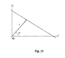
- the linear regression function also called LineFit, calculates the straight line that passes closest to all input points.
- Figure 12 shows an example of line fit algorithm. The visualized points don't belong to the same straight line, but the linear regression model uses the least squares approach to calculate the best line.
- the system in order to increase the accuracy of the research of DMTX (e.g. the one represented in Figure 13 ), implements two functions called SearchStartEndBLW and SearchStartEndBLH that find the start and stop of BLW and BLH.
- BaseLineWidth (BLW) and BaseLineHeight (BLH) are the two orthogonal segments which delimit rectangular DMTX and they are normally used to identify the orientation of DTMX.
- the first test accepts and analyzes the BLW basically horizontal. Within this test, there is another check to find the position of DMTX. The lower quadrant (0° to 180°) or the upper quadrant (180° to 360°).
- the second test accepts and analyzes the BLW basically vertical. Within this test, there is another check to find the position of DMTX. The left quadrant (90° to 270°) or the right quadrant (270° to 90°).
- This function begins with a scan from the center of the BLW and goes to the external side to find where the BLW begins or finishes.
- the algorithm compares and sums a couple of three pixels.
- Figure 14 shows an example to illustrate the concept above.
- the algorithm checks always gl 1 and gl 2 but begins from X 1
- the third step begins from X 2 , and so on...
- the function SearchStartEndBLH finds the beginning and the end of BLH starting from the middle of points found by previous function SearchStartEndBLW. Once having found the points on the BLH, the algorithm refines the edge detection with a subpixel precision (see Figure 15 ).
- the algorithm compares and sums a couple of three pixels value.
- the system in order to increase the correct interpretation of the end of BLW, implements a function called SearchParallelBLH that searches the parallel line to the BLH because it is truncated or because there is not enough gap from white to black with respect to the dark zone surrounding the DTMX.
- SearchParallelBLH a function called SearchParallelBLH that searches the parallel line to the BLH because it is truncated or because there is not enough gap from white to black with respect to the dark zone surrounding the DTMX.
- SearchParallelBLH searches the parallel line to the BLH. This procedure executes a vertical profile to correctly find the end of DMTX highlighted with a small line in the image above. So, after having found the end of the BLW the function SearchParallelBLH verifies and searches the end of DMTX.
- the pictures shown in Figures 18A, 18B and 18C represent the vertical profile in progress. Figure 18C shows with a big grey cross the correct end of DMTX which is rightmost compared with the small grey cross ( Figure 18A, Figure 18B ).
- the maximum darkness of all the pixels of a digital representation of such circular segment is lower than a predetermined threshold (i.e. it doesn't need to be really white, the system will consider it a "white” background provided all pixels are lighter than such threshold). More generally, the minimum contrast between the circular segment and the rest of the substantially circular region must exceed a predetermined threshold.
- a predetermined threshold i.e. it doesn't need to be really white
- the minimum contrast between the circular segment and the rest of the substantially circular region must exceed a predetermined threshold.
- Other alternative embodiments are possible, e.g. there is no need that "black” background covers the whole circular segment: it could be for example a rectangle surrounding the data matrix. Even more generally it is enough that the portion of circular crown containing the data matrix can be identified by the image processing system: as an example a visual mark can be placed to indicate where the portion of the circular crown containing the data matrix (i.e. the portion to be scanned) begins.
- the black segment (or better the intersection of the circular crown with the chord (or secant) defining the segment) is a possible implementation of such marking.
- the method is performed in a digital image processing system and aims at determining the position of a rectangular data matrix within a substantially circular region (e.g. of a circular label), the data matrix being positioned within a predetermined circular crown region and within a circular segment of the substantially circular region; as mentioned above the circular segment has a background minimum darkness higher than a predetermined threshold (or lower than a predetermined threshold), the circular crown region being defined by an inner circle and by an outer circle having the center substantially coincident with the center of the substantially circular region.
- the method begins at black circle 1901 and then goes to 1903 where a digital representation of the circular region on the label is acquired by the system.
- the label does not necessarily need to be circular; the method can work equally well with other shapes, provided a circular region with the above mentioned characteristics are included. In other words it is enough that position of the DataMatrix can be identified with reference to the center of DOT and within the circular crown and circular segment as discussed above.
- the system then processes the image and at step 1905 the method according to a preferred embodiment of the present invention determines the center of DOT; examples and details of the way of determining such center has been discussed above and those skilled in the art will easily appreciate that several state of the art methods and techniques can be used and combined together for such purpose.
- determining the center of DOT includes identifying the edge of the substantially circular with an horizontal scan and a vertical scan: the horizontal scan aims at identifying a transition point where the difference between the level of gray of neighboring pixels is exceeding a predetermined value, the horizontal transition point being indicative of a lateral edge (right and/or left) of the substantially circular region; the vertical scan does the same for vertical edge (upper and/or lower edge).
- a ring area including the DataMatrix is then identified: once the center of DOT is determined, the ring area included within an inner and an outer circle can be easily identified. Such ring area will intersect in two points the edge of the "black” (or “white, see comments above) circular sector: step 1909 of the method according to a preferred embodiment of the present invention radially scans the ring area in order to determine one of such intersections. The scan can be performed clockwise or counterclockwise: in the present example it is clockwise.
- a radial scan starting for the edge of the circular sector is performed in order to identify the edge of the DataMatrix, as explained in more details above.
- the information carried by the DataMatrix can be read and processed with state of the art methods.
Priority Applications (8)
| Application Number | Priority Date | Filing Date | Title |
|---|---|---|---|
| EP12185478.0A EP2711866A1 (fr) | 2012-09-21 | 2012-09-21 | Procédé et système pour détecter un code-barres en 2D dans une étiquette circulaire |
| PL13770861T PL2898449T3 (pl) | 2012-09-21 | 2013-09-19 | Sposób i system do wykrywania dwuwymiarowego kodu kreskowego na okrągłej etykiecie |
| PCT/EP2013/069460 WO2014044747A1 (fr) | 2012-09-21 | 2013-09-19 | Procédé et système de détection d'un code à barres en 2d dans une étiquette circulaire |
| US14/428,761 US9292725B2 (en) | 2012-09-21 | 2013-09-19 | Method and system for detecting 2D barcode in a circular label |
| EP13770861.6A EP2898449B1 (fr) | 2012-09-21 | 2013-09-19 | Procédé et système pour détecter un code-barres en 2d dans une étiquette circulaire |
| PT137708616T PT2898449T (pt) | 2012-09-21 | 2013-09-19 | Resumo |
| ES13770861.6T ES2612884T3 (es) | 2012-09-21 | 2013-09-19 | Método y sistema para detectar un código de barras en 2D en una etiqueta circular |
| CN201380047988.0A CN104641381B (zh) | 2012-09-21 | 2013-09-19 | 用于检测圆形标签中的2d条形码的方法和系统 |
Applications Claiming Priority (1)
| Application Number | Priority Date | Filing Date | Title |
|---|---|---|---|
| EP12185478.0A EP2711866A1 (fr) | 2012-09-21 | 2012-09-21 | Procédé et système pour détecter un code-barres en 2D dans une étiquette circulaire |
Publications (1)
| Publication Number | Publication Date |
|---|---|
| EP2711866A1 true EP2711866A1 (fr) | 2014-03-26 |
Family
ID=47257407
Family Applications (2)
| Application Number | Title | Priority Date | Filing Date |
|---|---|---|---|
| EP12185478.0A Withdrawn EP2711866A1 (fr) | 2012-09-21 | 2012-09-21 | Procédé et système pour détecter un code-barres en 2D dans une étiquette circulaire |
| EP13770861.6A Active EP2898449B1 (fr) | 2012-09-21 | 2013-09-19 | Procédé et système pour détecter un code-barres en 2d dans une étiquette circulaire |
Family Applications After (1)
| Application Number | Title | Priority Date | Filing Date |
|---|---|---|---|
| EP13770861.6A Active EP2898449B1 (fr) | 2012-09-21 | 2013-09-19 | Procédé et système pour détecter un code-barres en 2d dans une étiquette circulaire |
Country Status (7)
| Country | Link |
|---|---|
| US (1) | US9292725B2 (fr) |
| EP (2) | EP2711866A1 (fr) |
| CN (1) | CN104641381B (fr) |
| ES (1) | ES2612884T3 (fr) |
| PL (1) | PL2898449T3 (fr) |
| PT (1) | PT2898449T (fr) |
| WO (1) | WO2014044747A1 (fr) |
Cited By (1)
| Publication number | Priority date | Publication date | Assignee | Title |
|---|---|---|---|---|
| CN110096920A (zh) * | 2019-04-22 | 2019-08-06 | 浙江大学滨海产业技术研究院 | 一种面向视觉伺服的高精度高速定位标签和定位方法 |
Families Citing this family (5)
| Publication number | Priority date | Publication date | Assignee | Title |
|---|---|---|---|---|
| US10288410B2 (en) * | 2016-11-10 | 2019-05-14 | The Boeing Company | Method and system for identifying wire contact insertion holes of a connector |
| CN107492091B (zh) * | 2017-07-06 | 2020-09-04 | 东莞理工学院 | 基于机器视觉的标签外观检测方法及终端设备 |
| CN108256522B (zh) * | 2018-01-09 | 2020-05-19 | 北京航空航天大学 | 一种spr与波导混合吸收谱特征位置的二维识别方法 |
| CN109724990B (zh) * | 2019-01-08 | 2021-08-06 | 上海大学 | 一种包装盒标签中喷码区域的快速定位与检测方法 |
| KR20220073261A (ko) * | 2020-11-26 | 2022-06-03 | 주식회사 엘지에너지솔루션 | 전지셀 제조 방법 및 파우치 성형 장치 |
Citations (2)
| Publication number | Priority date | Publication date | Assignee | Title |
|---|---|---|---|---|
| EP1143372A2 (fr) * | 2000-04-06 | 2001-10-10 | Seiko Epson Corporation | Méthode et dispositif pour la lecture d'un code à barres bi-dimensionnel et support de stockage de données |
| US20060269136A1 (en) * | 2005-05-23 | 2006-11-30 | Nextcode Corporation | Efficient finder patterns and methods for application to 2D machine vision problems |
Family Cites Families (4)
| Publication number | Priority date | Publication date | Assignee | Title |
|---|---|---|---|---|
| US5798514A (en) * | 1996-01-11 | 1998-08-25 | Accumed Inc. | Circular bar code |
| FR2846432B1 (fr) * | 2002-10-24 | 2005-03-11 | Commissariat Energie Atomique | Cible codee et procede de photogrammetre utilisant de telles cibles |
| EP1422657A1 (fr) * | 2002-11-20 | 2004-05-26 | Setrix AG | Méthode de détection de la présence de figures et méthodes de gestion de stocks de composants |
| US7571864B2 (en) * | 2005-12-16 | 2009-08-11 | Pisafe, Inc. | Method and system for creating and using barcodes |
-
2012
- 2012-09-21 EP EP12185478.0A patent/EP2711866A1/fr not_active Withdrawn
-
2013
- 2013-09-19 US US14/428,761 patent/US9292725B2/en active Active
- 2013-09-19 ES ES13770861.6T patent/ES2612884T3/es active Active
- 2013-09-19 PT PT137708616T patent/PT2898449T/pt unknown
- 2013-09-19 CN CN201380047988.0A patent/CN104641381B/zh active Active
- 2013-09-19 PL PL13770861T patent/PL2898449T3/pl unknown
- 2013-09-19 EP EP13770861.6A patent/EP2898449B1/fr active Active
- 2013-09-19 WO PCT/EP2013/069460 patent/WO2014044747A1/fr active Application Filing
Patent Citations (2)
| Publication number | Priority date | Publication date | Assignee | Title |
|---|---|---|---|---|
| EP1143372A2 (fr) * | 2000-04-06 | 2001-10-10 | Seiko Epson Corporation | Méthode et dispositif pour la lecture d'un code à barres bi-dimensionnel et support de stockage de données |
| US20060269136A1 (en) * | 2005-05-23 | 2006-11-30 | Nextcode Corporation | Efficient finder patterns and methods for application to 2D machine vision problems |
Cited By (2)
| Publication number | Priority date | Publication date | Assignee | Title |
|---|---|---|---|---|
| CN110096920A (zh) * | 2019-04-22 | 2019-08-06 | 浙江大学滨海产业技术研究院 | 一种面向视觉伺服的高精度高速定位标签和定位方法 |
| CN110096920B (zh) * | 2019-04-22 | 2022-05-17 | 浙江大学滨海产业技术研究院 | 一种面向视觉伺服的高精度高速定位标签和定位方法 |
Also Published As
| Publication number | Publication date |
|---|---|
| US9292725B2 (en) | 2016-03-22 |
| EP2898449B1 (fr) | 2016-11-09 |
| PL2898449T3 (pl) | 2017-04-28 |
| PT2898449T (pt) | 2017-02-10 |
| EP2898449A1 (fr) | 2015-07-29 |
| CN104641381A (zh) | 2015-05-20 |
| US20150278571A1 (en) | 2015-10-01 |
| WO2014044747A1 (fr) | 2014-03-27 |
| ES2612884T3 (es) | 2017-05-19 |
| CN104641381B (zh) | 2017-05-24 |
Similar Documents
| Publication | Publication Date | Title |
|---|---|---|
| EP2898449B1 (fr) | Procédé et système pour détecter un code-barres en 2d dans une étiquette circulaire | |
| KR100361385B1 (ko) | 2차원코드인식방법 | |
| US7982201B2 (en) | System and method for detection of liquid level in a vessel | |
| EP3357842A1 (fr) | Système d'automatisation de laboratoire | |
| CN103543277B (zh) | 一种基于灰度分析与种类识别的血型结果识别算法 | |
| US8925821B2 (en) | Method for locating an optical identification on a laboratory analysis cuvette | |
| WO2019187420A1 (fr) | Procédé de traitement d'image, dispositif de traitement d'image, programme et support d'enregistrement | |
| US20090110253A1 (en) | System and Method for Preventing Sample Misidentification in Pathology Laboratories | |
| JP2006234515A (ja) | 容器内の異物検査方法およびその装置 | |
| WO2021205737A1 (fr) | Dispositif d'analyse d'échantillon biologique | |
| KR101842535B1 (ko) | 부호의 광학적 검출 방법 | |
| JP4167135B2 (ja) | 光学的情報読取装置 | |
| EP4012610A1 (fr) | Procédé de détection de la présence d'échantillon et dispositif associé | |
| CN114174832A (zh) | 一种样本分析系统及样本管理方法 | |
| CN114339046B (zh) | 基于自动旋转试管的图像采集方法、装置、设备及介质 | |
| CN113850200B (zh) | 一种基因芯片的判读方法、装置、设备及存储介质 | |
| EP3954990A1 (fr) | Dispositif de fixation de bandelette d'essai pour des mesures optiques d'un analyte | |
| JP4238796B2 (ja) | 光学的情報読取方法 | |
| US20230296875A1 (en) | Microscopy System and Method for Determining an Orientation of a Sample Carrier | |
| US20230230399A1 (en) | Instrument parameter determination based on Sample Tube Identification | |
| EP4280968A1 (fr) | Dispositifs microfluidiques et leur traitement rapide | |
| KR200285409Y1 (ko) | 영상처리를 용이하게 하는 마커를 갖춘 바이오 칩 | |
| CN116367922A (zh) | 用于识别实验器材的方法和设备 | |
| JP2014000081A (ja) | 画像処理装置、プログラム及び画像処理システム |
Legal Events
| Date | Code | Title | Description |
|---|---|---|---|
| PUAI | Public reference made under article 153(3) epc to a published international application that has entered the european phase |
Free format text: ORIGINAL CODE: 0009012 |
|
| AK | Designated contracting states |
Kind code of ref document: A1 Designated state(s): AL AT BE BG CH CY CZ DE DK EE ES FI FR GB GR HR HU IE IS IT LI LT LU LV MC MK MT NL NO PL PT RO RS SE SI SK SM TR |
|
| AX | Request for extension of the european patent |
Extension state: BA ME |
|
| STAA | Information on the status of an ep patent application or granted ep patent |
Free format text: STATUS: THE APPLICATION IS DEEMED TO BE WITHDRAWN |
|
| 18D | Application deemed to be withdrawn |
Effective date: 20140927 |